1
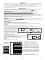
Carson Manufacturing Co., Inc.
5451 North Rural Street
Indianapolis, IN 46220
Phone: (888) 577-6877 Fax: (317) 254-2667
www.carsonsirens.com
SB-008-10
SWITCH CONTROL BOX
INSTALLATION AND OPERATING INSTRUCTIONS
SPECIFICATIONS
Input Voltage
Input Current
Output Current
Operating Temperature
Controls
Connections
Size
Weight
10 - 16 VDC (negative ground)
160 AMPS Max. (80 AMPS for Switch 1 – 4; 80 AMPS for switch 5 – 8)
20 AMPS each, each output protected with internal fuse.
Option to combine Output 1 and 2 for 40 AMP total output on switch 1 or 2.
-15° F to +140°F
(8) ON/OFF push-button switches with backlit changeable legends. Legend changes color when activated.
Internal option switch combines switch 1 and 2. When switch 1 or 2 is pressed, both outputs 1 and 2 activate.
Internal option switch changes switch 8 to momentary. Output 8 is activated for 10 seconds nominal.
(2) Positive #6AWG Wire Power Input, (2) Four Position Harness #10AWG Wire Output
(1)Positive and Negative Plug #22AWG Wire to power internal electronics and backlight.
6-1/8" Wide, 1-3/8" High, 6-1/2" Deep
2 –1/2 LBS.
NOTICE
Due to continuous product improvements, we must reserve the right to change any specifications and information, contained in this manual at
any time without notice.
Carson Manufacturing Co., Inc. makes no warranty of any kind with regard to this manual, including, but not limited to, the implied warranties
of merchantability and fitness for a particular purpose.
Carson Manufacturing Co., Inc. shall not be liable for errors contained herein or for incidental or consequential damages in connection with the
furnishing, performance, or use of this manual.
LIMITED WARRANTY
Carson Manufacturing Company, Inc. warrants this new product to be free from defects in material and workmanship, under normal use and service, for a period of five (5) years from the
date of delivery to the first user-purchaser.
During this warranty period the obligation of Carson Manufacturing is limited to repairing or replacing, as Carson Manufacturing may elect, any part or parts of such product which after
examination by Carson Manufacturing is determined to be defective in material and/or workmanship. This warranty does not cover labor charges for removal or re-installation of the
product. Fuses and lamps are not covered under this warranty. This warranty does not extend to any unit that has been subjected to abuse, misuse, improper installation or which has
not been adequately maintained, nor to units which have problems related to service or modification at any facility other than the manufacturer.
THERE ARE NO OTHER WARRANTIES, EXPRESSED OR IMPLIED, INCLUDING BUT NOT LIMITED TO, ANY IMPLIED WARRANTIES OF MERCHANTABILITY OR FITNESS FOR A
PARTICULAR PURPOSE. IN NO EVENT SHALL CARSON MANUFACTURING COMPANY, INC. BE LIABLE FOR ANY LOSS OF PROFITS OR ANY INDIRECT OR
CONSEQUENTIAL DAMAGES ARISING OUT OF ANY SUCH DEFECT IN MATERIALS OR WORKMANSHIP.
RETURN
If you have any questions concerning this or any other Carson product, please contact our Technical Service Department at
(888) 577-6877. Many issues can be handled over the phone. We can also be reached via e-mail at [email protected]
If a product must be returned for any reason, please contact our Technical Service Department to obtain a Returned Merchandise
Authorization number (RMA#) before you ship the product to Carson. Please write the RMA# clearly on the package near the mailing label.
Be sure to provide a return address, contact and phone number, along with a brief description of the problem.
CP4914C
Page 1 of 2
08/08/05
OPERATION
Each pushbutton switch on the face of the unit controls a corresponding output on the back. The pushbutton switch is push on/push off
operation. When pushed on, the legend above the switch will light red and +VDC is supplied to corresponding output. The units backlighting
may be connected to vehicles accessory panel. See OPTION SWITCHES below for further operational enhancements.
If the internal fuse ruptures the output will automatically de-activate. If a button is pressed and released but the red light will not stay on then
the fuse is blown and must be replaced.
INSTALLATION
Proper installation of the unit is essential for years of safe, reliable operation. Please read all instruction before installing the unit. Failure to
follow these instructions can cause serious damage to the unit or vehicle and may void warranties.
SAFETY PRECAUTIONS
For the safety of the installer, vehicle operator, passengers and the community please observe the following safety precautions.
Failure to follow all safety precautions and instructions may result in property damage, injury or death.
Qualifications - The installer must have a firm knowledge of basic electricity, vehicle electrical systems, and emergency equipment.
Mounting - Mount the control box for easy access by the vehicle operator. DO NOT mount in air bag deployment area. Assure clearances
before drilling in vehicle. To prevent internal damage to the unit, mounting bolts must not enter case more than 1/4".
Wiring - Use wiring capable of handling the current required. Make sure all connections are tight. Route wiring to prevent wear, overheating
and interference with air bag deployment. Install and check all wiring before connection to vehicle battery.
Testing - Test all functions after installation to assure proper operation.
UNPACKING
Inspect contents for shipping damage. If found alert carrier immediately. Contents should include switch control box, mounting bracket and
2 bolts, two power input cables, two power output cables, backlight and grounding cable, sheet of legends, and these instructions. Contact
supplier immediately if any components are missing.
OPTION SWITCHES
Remove cover (single screw on back) to gain access to option switches inside the unit.
Combo option switch (behind switch 1) combines output 1 and 2 to be activated by switch 1 or 2.
Momentary option switch (behind switch 8) sets switch 8 for momentary operation. Output 8 will activate for 10 seconds then de-activate.
LEGENDS
Multiple legends are supplied on a single sheet. Legends may be selected to match the device controlled.
Select the legend and place centered over the legend area. Press down on the legend to stick over clear window and tuck under rubber
framing. Gently lift up on the sides of rubber framing to help cover the edges of the legend.
To remove a legend, use a thin edge to gently
push rubber frame aside and pry between legend
and clear window. Try not to puncture clear
window. The stick-on adhesive is strong.
Blank (black) legends are provided for switches
with no function. The white background legends
may be written on with permanent marker to create
custom legends.
Legend
Area
Legend Label
Rubber Frame
1
Clear Window
POWER
LOAD LIMITATION (STROBES)
Loads such as strobes that have a high inrush current require a secondary relay. This
is because the high inrush current may exceed the output rating causing the units
internal relay contacts to weld together and get stuck on.
A 40A BOSCH SPST relay is recommended for the secondary relay.
OUTPUT
FROM
UNIT
BOSCH
RELAY
STROBE
LOAD
WIRING
Refer to the following diagram for electrical hookup.
Red #6 AWG
Switch 1 through 8 on
face correspond to
outputs 1 through 8
Recommended
Wire Size
Amps
Size
5 - 10
#16
10 - 15
#14
15 - 25
#12
25 - 40
#10
40 - 60
#8
60 - 80
#6
+VDC input supply for output 1 through 4
80A Input Max. Recommend adding 100A breaker.
Red
#22 AWG +VDC input for 30mA backlighting (optional)
Black #22 AWG –VDC for 1A relay control (not optional)
Yellow #10 AWG Output 1 - 20A Max. (Internal ATO Style Fuse)
Green #10 AWG Output 2 - 20A Max. (Internal ATO Style Fuse)
Blue
UNIT
#10 AWG Output 3 - 20A Max. (Internal ATO Style Fuse)
White #10 AWG Output 4 - 20A Max. (Internal ATO Style Fuse)
Yellow #10 AWG Output 5 - 20A Max. (Internal ATO Style Fuse)
Green #10 AWG Output 6 - 20A Max. (Internal ATO Style Fuse)
Blue
#10 AWG Output 7 - 20A Max. (Internal ATO Style Fuse)
White #10 AWG Output 8 - 20A Max. (Internal ATO Style Fuse)
Use next larger size
if longer than 10 ft.
Red #6 AWG
CP4914C
Page 2 of 2
+VDC input supply for output 5 through 8
80A Input Max. Recommend adding 100A breaker.
08/08/05