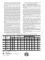
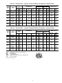
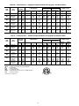
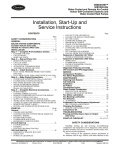
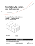
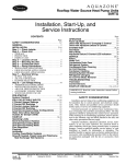
1
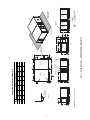
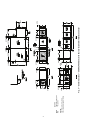
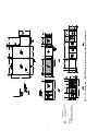
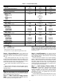
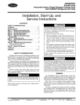
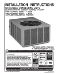
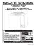
ROOMTOP®
50AH024-096
Horizontal Indoor Single-Package Cooling Units
with PURON® Refrigerant (R-410A)
Installation, Start-Up, and
Service Instructions
CONTENTS
SAFETY CONSIDERATIONS . . . . . . . . . . . . . . . . . . . . . . 1
GENERAL . . . . . . . . . . . . . . . . . . . . . . . . . . . . . . . . . . . . . . . . 1
INSTALLATION . . . . . . . . . . . . . . . . . . . . . . . . . . . . . . . . 1-17
Step 1 — Receive and Inspect Unit . . . . . . . . . . . . . . . 1
Step 2 — Protect Unit from Damage . . . . . . . . . . . . . . 1
Step 3 — Provide Unit Support . . . . . . . . . . . . . . . . . . . 1
Step 4 — Rig and Place Unit . . . . . . . . . . . . . . . . . . . . . 8
Step 5 — Make Condensate Piping
Connections. . . . . . . . . . . . . . . . . . . . . . . . . . . . . . . . . . . . 8
Step 6 — Install Ductwork . . . . . . . . . . . . . . . . . . . . . . . . 8
Step 7 — Split Systems (Factory Option,
if Required). . . . . . . . . . . . . . . . . . . . . . . . . . . . . . . . . . . . . 8
Step 8 — Make Electrical Connections . . . . . . . . . . 10
• FIELD CONTROL WIRING
• THERMOSTAT WIRE
Step 9 — Adjust Fan Speed . . . . . . . . . . . . . . . . . . . . . 10
START-UP . . . . . . . . . . . . . . . . . . . . . . . . . . . . . . . . . . . . . . . 17
SERVICE . . . . . . . . . . . . . . . . . . . . . . . . . . . . . . . . . . . . . .17,18
SAFETY CONSIDERATIONS
Installing and servicing air-conditioning equipment can be
hazardous due to system pressure and electrical components.
Only trained and qualified service personnel should install,
repair, or service air-conditioning equipment.
Untrained personnel can perform basic maintenance functions such as cleaning coils and filters and replacing filters. All
other operations should be performed by trained service personnel. When working on air-conditioning equipment, observe
precautions in the literature and on tags and labels attached to
unit.
Follow all safety codes. Wear safety glasses and work
gloves. Use quenching cloth for unbrazing operations. Have
fire extinguisher available.
WARNING
Disconnect all power to the unit before performing maintenance or service. Electrical shock and personal injury could
result.
NOTE: Ensure voltage on unit agrees with voltage listed on
the unit rating plate.
GENERAL
The 50AH024-096 units are single-package, indoor, horizontally mounted air conditioners of 2 to 8 tons capacity. The
50AH units are ASHRAE (American Society of Heating, Refrigerating and Air Conditioning Engineers) 90.1 compliant.
These units can be mounted as factory-shipped singlepackage units or can be separated and mounted as a split
system. If unit is split, the condensing section must be mounted
horizontally.
All units are designed to be ducted on both the condenser
and evaporator sides. Centrifugal blowers are used to ensure
quiet air delivery to the conditioned space. Sound level
requirements should be determined before final unit installation site is chosen.
Unit servicing is relatively simple since access to the condenser and evaporator motors, blowers, belt, and pulley is
gained through access panels located on the sides of the unit.
These panels may also be used for cleaning of condenser coils.
Unit side panels also provide access to control box and pressure switches.
Refrigeration cycle components (e.g., compressor, filter
drier, etc.) can be serviced upon removal of the base unit from
the space.
INSTALLATION
WARNING
Determine building alterations required to run piping, wiring, and ductwork. Follow dimensional drawings carefully
for ductwork, piping locations, electrical wiring, and overall unit dimensions. Read all installation instructions before
starting installation.
The 50AH units are intended for indoor installation only.
Step 1 — Receive and Inspect Unit — Unpack and
check unit against shipping order. See Fig. 1 for model number
nomenclature. Inspect carefully for concealed shipping damage. If unit is damaged or incomplete, file claim with transportation company and advise Carrier immediately.
Step 2 — Protect Unit from Damage — To main-
tain warranty, unit must be protected against theft and vandalism and stored indoors at all times.
Step 3 — Provide Unit Support — Refer to Fig. 2-5
for unit dimensions. Refer to Table 1 for unit sizes and weights.
Each unit requires the following field-supplied items:
8 — threaded suspension rods (3/8-in.-16 SAE Grade 1
minimum), 4 additional rods are needed if the unit
has a factory-installed air-side economizer
8 — washers
8 — locknuts
Install the 8 field-supplied rods by suspending them from a
suitable ceiling support. Locate rods to mate with 8 outside corner rigging holes shown in Fig. 2-5. Unit center of gravity is
shown in Fig. 6.
The ceiling and ceiling supports of existing buildings may
require reinforcements; follow all applicable codes.
Manufacturer reserves the right to discontinue, or change at any time, specifications or designs without notice and without incurring obligations.
Catalog No. 04-53500057-01
Printed in U.S.A.
Form 50AH-14SI
Pg 1
5-10
Replaces: 50AH-12SI
50AH AC 048 5
–
–
–
–
2
1
XX
Factory-Installed Options
50AH – Horizontal, Indoor
Single-Package Cooling Unit
Packaging
1 – Domestic
2 – Export
Compressor Options
AC – Air Cooled
Design Changes
2 – R-410A Original Design
Unit Size - Nominal Tons
024 – 2
060 – 5
036 – 3
072 – 6
048 – 4
096 – 8
Economizer and Hot Gas Options
– – None
A – Hot Gas Bypass†
B – Hot Gas Reheat†
C – Air-Side Economizer with Controls
D – Hot Gas Bypass and Hot Gas Reheat†
E – Hot Gas Bypass and Air-Side Economizer†
F – Hot Gas Bypass, Air-Side Economizer, and
Hot Gas Reheat†
G – Hot Gas Reheat and Air-Side Economizer†
Voltage Description
3 – 208/230-1-60
5 – 208/230-3-60
6 – 460-3-60
Evaporator Configuration
– – Standard Motor with Standard Drive
A – Standard Motor with Alternate 1 Drive
B – Standard Motor with Alternate 2 Drive
C – Upgrade 1 Motor with Standard Drive
D – Upgrade 1 Motor with Alternate 1 Drive
E – Upgrade 1 Motor with Alternate 2 Drive
F – Upgrade 2 Motor with Alternate 1 Drive
G – Upgrade 2 Motor with Alternate 2 Drive
H – Upgrade 3 Motor with Alternate 2 Drive
Cabinet Type
– – Standard
S – Splittable*
Condenser Configuration
– – Standard Motor with Standard Drive
A – Standard Motor with Standard Drive, Flooded Condenser
B – Standard Motor with Alternate 1 Drive
C – Upgrade 1 Motor with Alternate 1 Drive
D – Upgrade 1 Motor with Alternate 2 Drive
E – Upgrade 1 Motor with Alternate 3 Drive
F – Upgrade 2 Motor with Alternate1 Drive
G – Upgrade 2 Motor with Alternate 2 Drive
H – Upgrade 2 Motor with Alternate 3 Drive
J – Standard Motor with Alternate 1 Drive, Flooded Condenser
K – Upgrade 1 Motor with Alternate 1 Drive, Flooded Condenser
L – Upgrade 1 Motor with Alternate 2 Drive, Flooded Condenser
M – Upgrade 1 Motor with Alternate 3 Drive, Flooded Condenser
N – Upgrade 2 Motor with Alternate1 Drive, Flooded Condenser
P – Upgrade 2 Motor with Alternate 2 Drive, Flooded Condenser
Q – Upgrade 2 Motor with Alternate 3 Drive, Flooded Condenser
a50-8546
* Includes interconnecting kit and electrical box.
†Not available with splitable units.
Fig. 1 — Model Number Nomenclature
2
3
18 3/4
1 3/4
AIR
OUT
16 1/8
024
036
048
060
UNIT
50AH
B
111
111
116
117
CLEARANCE HOLE FOR
3/8" HANGING ROD
TYP 8 PLS
REAR
64 1/2
DETAIL A
A
87
87
91
91
2
28
3 13/16
2 1/4
H
G
LEFT
TOP
F A
E B
3 7/8
G
105
106
111
112
D
FILTER
ACCESS
C
62
24
FRONT
RETURN
AIR
34 3/4
60
RIGHT
36 IN. SERVICE
CLEARANCE
1 3/8
3 3/4
3 1/2
1
OSA
RA
1
1 15/16
CONDENSATE DRAIN
7/8" OD
COIL
ACCESS
QUICK
CONNECT
ACCESS
42
EVAP
SECTION
38 1/8
H
100
101
106
107
SUPPLY
AIR
13 5/8
REAR
LEFT
6 7/16
1
31
ISOMETRIC VIEW
12 3/8
9 5/16
Fig. 2 — Unit Dimensions — 50AH024-060 Standard Units
AIR
IN
33
COMPRESSOR
ACCESS
48
DETAIL "A"
COND
SECTION
44 1/8
WEIGHT OF CORNER (lb)
C
D
E
F
88
113
143
136
89
114
144
138
92
118
152
145
93
119
153
146
OPERATING WEIGHT DISTRIBUTION
NOTE: Dimensions are in inches.
6 1/8
a50-8547
OSA
RA
ELECT
BOX
ACCESS
90
RIGHT
MOTOR
ACCESS
BLOWER
ACCESS
LEGEND
— Outside Supply Air
— Return Air
MOTOR
ACCESS
ELECTRICAL
CONNECTIONS
TYP
26 IN. SERVICE
CLEARANCE
FRONT
4
0 lbs.
LEGEND
— Outside Supply Air
— Return Air
NOTES:
1. Dimensions are in inches.
2. Economizer weight is 180 lb.
OSA
RA
16 1/8
64 1/2
13 5/8
1 1/2
9 5/16
12 3/8
6 7/16
2 1/4
5 7/8
3 13/16
44 1/8
3 7/8
6 1/16
5 15/16
38 1/8
24 3/4
Fig. 3 — Unit Dimensions — 50AH024-060 Units with Factory-Installed Air-Side Economizer
3 1/4
5 7/8
6 1/8
18 3/4
1 3/4
12
1 15/16
3 1/4
38 1/2
a50-8548
5
REAR
75
ELECTRICAL
CONNECTIONS
TYP
MOTOR
ACC
B
128
129
COMPRESSOR
ACCESS
2
2 1/4
29
6
H
G
DETAIL "A"
LEFT
TOP
F A
E B
3 7/8
G
188
208
FILTER
ACCESS
C
D
CONDENSATE DRAIN
7/8" OD
COIL
ACCESS
47
EVAP
SECTION
43 1/8
H
192
212
3 5/8
25
1 1/4
3 1/2
1
OSA
72 1/2
1
RA
1 15/16
RETURN
AIR
39
FRONT
70 1/2
36 IN. SERVICE
CLEARANCE
36 IN. SERVICE
CLEARANCE
SUPPLY
AIR
16 1/16
REAR
RIGHT
6 7/16
6
1
32
ELECT
BOX
ACCESS
ISOMETRIC VIEW
18 3/4
Fig. 4 — Unit Dimensions — 50AH072,096 Standard Units
AIR
IN
53
65
COND
SECTION
61 1/8
WEIGHT OF CORNER (lb)
C
D
E
F
149
152
126
128
149
153
139
142
NOTE: Dimensions are in inches.
ELECT
BOX
ACCESS
A
125
126
CLEARANCE HOLE FOR
3/8" HANGING ROD
TYP 8 PLS
DETAIL A
072
096
UNIT
50AH
OPERATING WEIGHT DISTRIBUTION
MOTOR
ACCESS
OSA
RA
RIGHT
AIR
OUT
22 1/8
BLOWER
ACCESS
21 7/16
10 7/8
18 15/16
LEGEND
— Outside Supply Air
— Return Air
QUICK
CONNECT
ACCESS
112
26 IN. SERVICE
CLEARANCE
LEFT
FRONT
a50-8549
6
LEGEND
— Outside Supply Air
— Return Air
NOTES:
1. Dimensions are in inches.
2. Economizer weight is 200 lbs.
OSA
RA
70 1/2
16 1/16
1 1/2
6 7/16
6 5/8
18 3/4
2 1/4
5 7/8
61 1/8
3 7/8
43 1/8
5 15/16
6 1/16
22 1/8
29 3/4
21 7/16
3 1/4
10 7/8
18 15/16
42 1/2
Fig. 5 — Unit Dimensions — 50AH072,096 Units with Factory-Installed Air-Side Economizer
3 1/4
13 7/16
12
72 1/2
1 15/16
a50-8550
CENTER OF GRAVITY
DIMENSIONS (in.)
A
B
29.0
25.6
28.8
26.0
29.0
27.0
28.8
26.8
59.3
31.2
60.0
31.5
UNIT 50AH
024
036
048
060
072
096
NOTE: Fasten threaded rods through holes in end frames as shown.
Use 4 rods on each side of unit for a total of 8.
CAUTION
All panels must be in place when rigging.
Fig. 6 — Rigging Details
Table 1 — Physical Data
UNIT 50AH
OPERATING WEIGHT (lb)
Base Unit
Evaporator/Condenser Sections
SHIPPING WEIGHT (lb)*
REFRIGERANT TYPE
Operating Charge (lb-oz)†
COMPRESSOR — TYPE
Quantity...Model
Oil (oz)
HPS Setting (psig)
Cutout
Reset
LPS Setting (psig)
Cutout
Reset
CONDENSATE DRAIN CONNECTION
Size (in.)...Type
CONDENSER COIL
Size (L x H) (in.)
Number of Rows...Fins/in.
CONDENSER FAN
Nominal Cfm
Blower Size (in.)
Motor Hp (Rpm)
Standard Motor
Upgrade 1 Motor
Upgrade 2 Motor
EVAPORATOR COIL
Size (L x H) (in.)
Number of Rows...Fins/in.
EVAPORATOR AIR FAN
Nominal Cfm
Blower Size (in.)
Motor Hp (Rpm)
Standard Motor
Upgrade 1 Motor
Upgrade 2 Motor
Upgrade 3 Motor
INDOOR-AIR FILTERS
Number...Size (in.)
INTERCONNECTING TUBING SIZE
Suction (Qty...in.)
Liquid (Qty...in.)
024
036
048
903
399/484
1036
910
401/489
1043
R-410A
4-5
Scroll
1...ZP31K5E
25
952
417/515
1085
4-5
1...ZP20K5E
25
8-8
1...ZP38K5E
42
650 ± 7
Manual Reset
75 ± 7
100 ± 7
7/ ...OD
8
Copper Tubes — Aluminum Fins
40 x 30
4...14
Centrifugal — Belt Drive
2000
15 x 15
40 x 30
4...14
1700
15 x15
0.33 (1725)
—
—
90 x 30
2...12
2500
15 x 15
0.33 (1725)
—
—
Copper Tubes — Aluminum Fins
32 x 16
3...12
Centrifugal — Belt Drive
1200
12 x 9
0.33 (1725)
0.50 (1725)
0.75 (1725)
0.33 (1725)
0.50 (1725)
0.75 (1725)
1.00 (1725)
2...18 x 24 x 1
0.33 (1725)
0.50 (1725)
0.75 (1725)
1.00 (1725)
Factory-Supplied Disposable Type
2...18 x 24 x 1
2...18 x 24 x 1
1...5/8
1...3/8
1...5/8
1...3/8
1...7/8
1...3/8
32 x 16
3...12
800
12 x 9
0.25 (1725)
0.33 (1725)
0.50 (1725)
—
LEGEND
HPS — High-Pressure Switch
LPS — Low-Pressure Switch
32 x 26
3...14
1600
12 x 9
NOTE: If components are to be split, the maximum length of refrigerant
tubing to be used is 50 equivalent ft, assuming components will be
installed in same horizontal plane. If components are not to be installed
in same horizontal plane, contact your Carrier representative for more
information. For additional piping information, refer to Carrier System
Design Manual, Part 3.
*Shipping weights include base unit plus packaging.
†If components are to be split, additional refrigerant will be needed.
7
Table 1 — Physical Data (cont)
UNIT 50AH
OPERATING WEIGHT (lb)
Base Unit
Evaporator/Condenser Sections
SHIPPING WEIGHT (lb)*
REFRIGERANT TYPE
Operating Charge (lb-oz)†
COMPRESSOR — TYPE
Quantity...Model
Oil (oz)
HPS Setting (psig)
Cutout
Reset
LPS Setting (psig)
Cutout
Reset
CONDENSATE DRAIN CONNECTION
Size (in.)...Type
CONDENSER COIL
Size (L x H) (in.)
Number of Rows...Fins/in.
CONDENSER FAN
Nominal Cfm
Blower Size (in.)
Motor Hp (Rpm)
Standard Motor
Upgrade 1 Motor
Upgrade 2 Motor
EVAPORATOR COIL
Size (L x H) (in.)
Number of Rows...Fins/in.
EVAPORATOR AIR FAN
Nominal Cfm
Blower Size (in.)
Motor Hp (Rpm)
Standard Motor
Upgrade 1 Motor
Upgrade 2 Motor
Upgrade 3 Motor
INDOOR-AIR FILTERS
Number...Size (in.)
INTERCONNECTING TUBING SIZE
Suction (Qty...in.)
Liquid (Qty...in.)
060
072
096
960
421/519
1093
1214
554/634
1647
R-410A
6-6
Scroll
2...ZP31K5E
25
1283
556/701
1716
8-8
1...ZPKP51K5E
42
6-6
2...ZP38K5E
42
650 ± 7
Manual Reset
75 ± 7
100 ± 7
7/8...OD
Copper Tubes — Aluminum Fins
40 x 30 (2 coils)
2...20
Centrifugal — Belt Drive
5200
18 x 18
90 x 30
2...12
3000
15 x 15
0.33 (1725)
0.50 (1725)
0.75 (1725)
40 x 30 (2 coils)
2...20
6400
18 x 18
1.00 (1725)
1.50 (1725)
—
Copper Tubes — Aluminum Fins
46 x 28
3...14
Centrifugal — Belt Drive
2400
15 x 15
1.50 (1725)
2.00 (1725)
3.00 (1725)
0.75 (1725)
1.00 (1725)
1.50 (1725)
2.00 (1725)
2...18 x 24 x 1
0.50 (1725)
0.75 (1725)
1.00 (1725)
1.50 (1725)
Factory-Supplied Disposable Type
2...20 x 25 x 1
2...20 x 25 x 1
1...7/8
1...3/8
1...5/8
1...3/8
1...7/8
1...7/8
32 x 26
3...14
2000
12 x 9
0.33 (1725)
0.50 (1725)
0.75 (1725)
1.00 (1725)
LEGEND
HPS — High-Pressure Switch
LPS — Low-Pressure Switch
46 x 28
3...14
3200
15 x 15
NOTE: If components are to be split, the maximum length of refrigerant
tubing to be used is 50 equivalent ft, assuming components will be
installed in same horizontal plane. If components are not to be installed
in same horizontal plane, contact your Carrier representative for more
information. For additional piping information, refer to Carrier System
Design Manual, Part 3.
*Shipping weights include base unit plus packaging.
†If components are to be split, additional refrigerant will be needed.
Step 4 — Rig and Place Unit — Move and store unit
Step 6 — Install Ductwork — Use flexible ductwork
to attach duct to unit and to help control transmission of vibrations to building structures. Attach ductwork to the return and
supply ends of both coils.
If unit is located with condenser close to outside of building,
install a field-supplied rainhood. Hood intake dimensions
should be same as condenser return-air dimensions. In addition, install a triple-layer bird screen over rainhood intake to
eliminate possibility of insects, birds, water, or debris from
entering unit. Ensure hood and/or louvers are installed correctly to avoid condenser air recirculation.
in horizontal position. Provide space around unit for service,
filter access, ductwork, and overhead clearance as indicated in
Fig. 2-5.
Using suitable hydraulic lift source, raise unit up to meet
bottom of the 8 threaded rods suspended from ceiling (12 rods
for units with air-side economizer). Center unit so that the 8 or
12 threaded rods can be easily inserted into the factory-drilled
holes at each end. Refer to Fig. 6 for rigging details.
Apply washers and locknuts on ends of each of the 8 or 12
rods.
Tighten locknuts sufficiently so that unit weight is supported entirely by the 8 or 12 rods. Level unit within the space by
adjusting locknuts.
Step 7 — Split Systems (Factory Option, if
Required) — The Roomtop® 50AH units may be split into
2 sections, if desired, with condensing section mounted
remotely horizontally. The unit must be ordered with the
“Splittable” cabinet type as shown in the unit model number
nomenclature. See Fig. 1. All splittable units come with the
interconnecting tubing kit.
Sections installed in the same horizontal plane may be separated by up to 50 equivalent ft of tubing. Use type L copper or
better.
IMPORTANT: Unit must be level to operate properly.
NOTE: For split systems, 8 (or 12) suspension rods are
required (4 for each section and 4 for economizer if required).
Refer to Splitting Systems section below.
Step 5 — Make Condensate Piping Connections — One 7/8-in. OD pipe thread condensate drain con-
nection is provided for the evaporator section.
8
Perform the following procedure:
1. For condensing section, hand thread the female halves of
the self-sealing couplings (supplied with the interconnect
tubing kit) onto the male couplings (factory supplied and
installed on the condensing section). Turn union nut approximately 1 to 11/2 turns. This is to make sure that the
interconnecting tubing will be routed and brazed with the
self-sealing couplings in their final proper location, so
that there will be no difficulty when the final coupling assembly is made.
2. For evaporator section, hand thread the male halves of the
self-sealing couplings (supplied with the interconnect
tubing kit) onto the female couplings (factory supplied
and installed on the evaporating section). Turn union nut
approximately 1 to 11/2 turns. This is to make sure that the
interconnecting tubing will be routed and brazed with the
self-sealing couplings in their final proper location, so
that there will be no difficulty when the final coupling assembly is made.
3. Run the interconnecting tubing required.
NOTE: Installations may be made with up to 50 ft equivalent line lengths by installing the recommended tube sizes and adding the necessary refrigerant. For equivalent
line lengths greater than 50 ft, contact Carrier for line sizing and additional accesories required.
Condensing section must be located in same plane as, or
above, evaporator section to maintain the liquid refrigerant seal
at the expansion device. This permits expansion device to feed
liquid refrigerant to evaporator coil properly. To split sections
(some of the following steps may be eliminated depending on
particular application):
1. Disconnect all electrical power to unit.
2. Remove the 10 size 10 drive screws that hold on the top
tie strap.
3. Remove the 8 size 3/8-in. drive bolts that hold on each
side angle.
4. Control panel access panels are held on with 2 size 10
drive screws for each panel. A standard 50AH024-060
unit has one control panel located in the evaporator section. A standard 50AH072 or 096 unit has a control panel
in both the evaporator and condenser sections.
5. Units have resealable fittings. Do not cut refrigerant piping. See Interconnecting Refrigerant Tubing section below for procedure on installing tubing.
6. Install evaporator and condensing sections in desired
locations.
7. Use sufficient length of refrigerant piping to reconnect
piping cut in previous step. Refer to Carrier System
Design Manual, Part 3, for additional piping data.
8. Recharge unit with R-410A. See Refrigerant Charge section on page 18 for more information.
After splitting sections, additional refrigerant must be added
to system to ensure proper refrigerant charge. The amount of
refrigerant to be added depends on length of tubing added to
system and operating temperatures of system. Refer to Carrier
System Design Manual, Chapter 3. Allow unit to operate at
least 10 minutes before adjusting refrigerant charge.
Since standard roomtop unit has negligible line losses, splitting the system can increase line loss and decrease system
capacity. Capacity reduction can be determined by referring to
Carrier System Design Manual.
INTERCONNECTING REFRIGERANT TUBING — The
interconnecting tubing kit comes with all factory-optional splittable units. After the separated sections have been installed, the
interconnecting tubing can be run, using the self-sealing couplings supplied in the interconnect tubing kit (see Fig. 7 and 8).
SELF-SEALING
COUPLING
(MALE HALF)
IMPORTANT: On units with more than one refrigerant circuit, be careful not to intermix lines of the
various circuits. If the connections were labeled
before disconnecting the couplings, this should not
be a problem. Half couplings may be removed to
make brazing to the interconnecting tubing more
convenient.
D
D
C
A
EVAPORATOR
SECTION
C
SELF-SEALING
COUPLING
(FEMALE HALF)
B
B
C
A — Male self-sealing fittings
B — Refrigerant piping between sections
C — Female self-sealing fittings
D — Schrader fittings
SCREWS
A
CONDENSING
SECTION
D
D
A
C
A
a50-8552
Fig. 8 — Tubing Installation
CAUTION
When brazing tubing to the self-sealing couplings, be sure
to use a wet rag, running water bath or chill blocks on the
quick-connects to prevent overheating the valves and damaging the seals.
SELF-SEALING
FLANGE
4. The interconnect tubing kit contains a sufficient number
of Schrader access valves to permit installation of one in
each end of both the liquid and suction lines of the fieldsupplied tubing. Each interconnecting line (suction, liquid, hot gas) must have one of the supplied Schrader access fittings installed into the field-supplied tubing, however, for short lengths of tubing, only one Schrader in
each line is necessary. Install the Schrader valve fittings
into the tubing before brazing the couplings onto the ends
a50-8551
Fig. 7 — Self Sealing Coupling
For dual circuits, 2 kits are supplied. It is recommended that
some refrigerant oil be placed on the coupling threads to facilitate threading.
9
section is more than 50 ft above the evaporator, consult
Carrier for specific refrigeration components.
of the tubing. Use a 1/4-in. hole to mount the valve. Clean
and debur the tubing before doing any brazing to ensure
that no chips or debris are left in the refrigerant circuit.
Remove the Schrader valve cap and core before doing
any brazing.
5. After brazing the tubing to the self-sealing coupling
halves, evacuate each line to 500 microns. Check to make
sure that each line holds a vacuum after removal of the
vacuum pump (indicating no leaks). Add the appropriate
charge of R-410A refrigerant using the Schrader valves.
Refasten male halves to outer back panel of evaporator
section with flanges and screws (if they were removed for
brazing to tubing). Wipe off coupling seals and threaded
surfaces with a clean cloth to prevent the inclusion of dirt
or foreign material into the system. Lubricate rubber seal
and metal seal in the male halves with refrigeration oil.
Thread coupling halves together by hand to ensure proper
mating of threads. Continue to handthread each half-coupling to its mating half until resistance is felt (approximately 11/2 to 13/4 turns). Complete the connection of the
mating half-couplings with a wrench. The suction line
couplings (size 12) will be totally engaged after an additional 51/2 to 53/4 turns. The liquid line couplings (size 8)
will be totally engaged after an additional 41/2 to 43/4
turns. Use a backup wrench to prevent the couplings from
twisting.
6. Refrigerant piping must be insulated in accordance with
local codes and/or applicable ASHRAE standards. Insulation exposed to weather must be suitable for outdoor
use. Provide protection from water and shielding from solar radiation as necessary.
7. Add refrigerant to the system to compensate for the additional interconnecting tubing. The suction line should be
pitched downward to the compressor, sloping approximately 1/4-in. every 10 ft to facilitate oil return. P-traps
(field supplied) are required for all suction line risers every 15 ft. When the evaporator is above the condensing
section, an inverted P-trap should be incorporated as
close as possible to the evaporator (this minimizes floodback/oil slugging during the off cycle). If the condensing
Step 8 — Make Electrical Connections — Connect power wiring to junction box located on unit side near
control box access panel. All wiring must comply
with National Electrical Code (NEC) and all local code
requirements.
Operating voltage to compressor must be within voltage
range as indicated on unit nameplate. On 3-phase units, voltages between phases must be balanced within 2% and current
must be balanced within 10%. Contact local power company
for correction of improper voltage or phase imbalance. Unit
failure as a result of operation on improper line voltage or excessive phase imbalance constitutes abuse and may cause damage to electrical components. Such operation would invalidate
any applicable Carrier warranty.
Install a fused disconnect per NEC. Refer to unit nameplate
and Tables 2A-2L for fuse sizes and wire amperages for all
units.
FIELD CONTROL WIRING — Install a Carrier-approved
accessory thermostat assembly according to installation
instructions provided by thermostat manufacturer. Locate
thermostat assembly on a solid wall in the conditioned space
away from drafts to sense average room temperature.
Using thermostat cable or equivalent single leads of no. 18
AWG (American Wire Gage) colored wire, route cable or wire
from the subbase terminals, up and through connector on unit
side (below power lead junction box) and connect to low-voltage terminal block inside the control box.
THERMOSTAT WIRE — Use 18 gage for 0 to 50-ft long
wires and 16 gage for 51 to 75-ft wire lengths.
Step 9 — Adjust Fan Speed — Adjust fan speed to
meet jobsite conditions. Refer to Tables 3 and 4 to determine
fan speed settings. See Service section of this document for
instructions to adjust fan speed.
The evaporator and condenser fan motors on all units are
belt drive.
Table 2A — Electrical Data — Standard Evaporator Motor with Standard Condenser Motor
UNIT
50AH
V-PH
(60 Hz)
024
208/230-1
208/230-1
208/230-3
460-3
208/230-1
208/230-3
460-3
208/230-1
208/230-3
460-3
208/230-1
208/230-3
460-3
208/230-1
208/230-3
460-3
036
048
060
072*
096*
HACR
Hp
FLA
LRA
MOCP
RLA
—
—
—
—
—
—
VOLTAGE
RANGE
FAN MOTORS
Evaporator
Condenser
(Standard)
(Standard)
COMPRESSOR
Min
Max
QTY
RLA
LRA
Hp
FLA
Hp
FLA
187
187
187
414
187
187
414
187
187
414
187
187
414
187
187
414
254
254
254
508
254
254
508
254
254
508
254
254
508
254
254
508
1
13.5
16.7
10.4
5.8
19.9
13.6
6.1
26.4
16.0
7.8
16.7
10.4
5.8
19.9
13.6
6.1
58.0
79.0
73.0
38.0
109.0
83.1
41.0
134
110.0
52.0
79.0
73.0
38.0
109.0
83.1
41.0
1 /4
1.25
1.7
1.3
0.7
1.7
1.3
0.7
1.7
1.3
0.7
2.5
1.8
0.9
3.2
2.4
1.2
1/3
1.7
1.7
1.3
0.7
1.7
1.3
0.7
1.7
1.3
0.7
4.2
3.2
1.6
6.5
4.8
2.4
1
1
1
2
2
LEGEND
Heating, Air Conditioning, and Refrigeration
Horsepower
Full Load Amps
Locked Rotor Amps
Maximum Overcurrent Protection (HACR breaker)
Rated Load Amps
*Unit has two compressors.
10
1/
3
1/
3
1 /3
1/
3
1/
3
1 /3
1/
3
1/
3
1 /3
1/
2
1/
2
1 /2
3/
4
3/
4
3 /4
1/
3
1/
3
1/3
1/
3
1/
3
1/3
1/
3
1/
3
1/3
1
1
1
1 1 /2
1 1 /2
1 1 /2
POWER SUPPLY
Min Ckt
Amps
19.8
24.3
15.6
8.6
28.3
19.6
8.9
36.4
22.6
11.1
44.3
28.4
15.6
54.5
37.8
17.3
MOCP
Amps
35
40
25
15
50
35
15
65
40
20
60
40
20
75
50
25
Table 2B — Electrical Data — Upgrade 1 Evaporator Motor with Standard Condenser Motor
UNIT
50AH
V-PH
(60 Hz)
024
208/230-1
208/230-1
208/230-3
460-3
208/230-1
208/230-3
460-3
208/230-1
208/230-3
460-3
208/230-1
208/230-3
460-3
208/230-1
208/230-3
460-3
036
048
060
072*
096*
VOLTAGE
RANGE
FAN MOTORS
Evaporator
Condenser
(Upgrade 1)
(Standard)
COMPRESSOR
Min
Max
QTY
RLA
LRA
Hp
FLA
Hp
FLA
187
187
187
414
187
187
414
187
187
414
187
187
414
187
187
414
254
254
254
508
254
254
508
254
254
508
254
254
508
254
254
508
1
13.5
16.7
10.4
5.8
19.9
13.6
6.1
26.4
16.0
7.8
16.7
10.4
5.8
19.9
13.6
6.1
58.0
79.0
73.0
38.0
109.0
83.1
41.0
134.0
110.0
52.0
79.0
73.0
38.0
109.0
83.1
41.0
1 /3
1.7
2.5
1.8
0.9
2.5
1.8
0.9
2.5
1.8
0.9
3.2
2.4
1.2
4.2
3.2
1.6
1/3
1.7
1.7
1.3
0.7
1.7
1.3
0.7
1.7
1.3
0.7
4.2
3.2
1.6
6.5
4.8
2.4
1
1
1
2
2
1/
2
1/
2
1 /2
1/
2
1/
2
1 /2
1/
2
1/
2
1 /2
3/
4
3/
4
3 /4
1
1
1
1/
3
1/
3
1/3
1/
3
1/
3
1/3
1/
3
1/
3
1/3
1
1
1
1 1 /2
1 1 /2
1 1 /2
POWER SUPPLY
Min Ckt
Amps
20.3
25.1
16.1
8.8
29.1
20.1
9.2
37.2
23.1
11.3
45.0
29.0
15.9
55.5
38.6
17.7
MOCP
Amps
35
40
25
15
50
35
15
65
40
20
60
40
20
75
50
25
Table 2C — Electrical Data — Upgrade 2 Evaporator Motor with Standard Condenser Motor
UNIT
50AH
V-PH
(60 Hz)
024
208/230-1
208/230-1
208/230-3
460-3
208/230-1
208/230-3
460-3
208/230-1
208/230-3
460-3
208/230-1
208/230-3
460-3
208/230-1
208/230-3
460-3
036
048
060
072*
096*
HACR
Hp
FLA
LRA
MOCP
RLA
—
—
—
—
—
—
VOLTAGE
RANGE
FAN MOTORS
Evaporator
Condenser
(Upgrade 2)
(Standard)
COMPRESSOR
Min
Max
QTY
RLA
LRA
Hp
FLA
Hp
FLA
187
187
187
414
187
187
414
187
187
414
187
187
414
187
187
414
254
254
254
508
254
254
508
254
254
508
254
254
508
254
254
508
1
13.5
16.7
10.4
5.8
19.9
13.6
6.1
26.4
16.0
7.8
16.7
10.4
5.8
19.9
13.6
6.1
58.0
79.0
73.0
38.0
109.0
83.1
41.0
134.0
110.0
52.0
79.0
73.0
38.0
109.0
83.1
41.0
1/
2.5
3.2
2.4
1.2
3.2
2.4
1.2
3.2
2.4
1.2
4.2
3.2
1.6
6.5
4.8
2.4
1/
1.7
1.7
1.3
0.7
1.7
1.3
0.7
1.7
1.3
0.7
4.2
3.2
1.6
6.5
4.8
2.4
1
1
1
2
2
LEGEND
Heating, Air Conditioning, and Refrigeration
Horsepower
Full Load Amps
Locked Rotor Amps
Maximum Overcurrent Protection (HACR breaker)
Rated Load Amps
*Unit has two compressors.
11
2
3/
4
3 /4
3/
4
3/
4
3 /4
3/
4
3/
4
3 /4
3/
4
1
1
1
11 / 2
1 1 /2
1 1 /2
3
1/
3
1/3
1/
3
1/
3
1/3
1/
3
1/
3
1/3
1/
3
1
1
1
1 1 /2
1 1 /2
1 1 /2
POWER SUPPLY
Min Ckt
Amps
21.1
25.8
16.7
9.1
29.8
20.7
9.5
37.9
23.7
11.6
46.0
29.8
16.3
57.8
40.2
18.5
MOCP
Amps
35
40
25
15
50
35
15
65
40
20
60
40
20
80
55
25
Table 2D — Electrical Data — Upgrade 3 Evaporator Motor with Standard Condenser Motor
UNIT
50AH
V-PH
(60 Hz)
024
208/230-1
208/230-1
208/230-3
460-3
208/230-1
208/230-3
460-3
208/230-1
208/230-3
460-3
208/230-1
208/230-3
460-3
208/230-1
208/230-3
460-3
036
048
060
072*
096*
VOLTAGE
RANGE
FAN MOTORS
Evaporator
Condenser
(Upgrade 3)
(Standard)
COMPRESSOR
Min
Max
QTY
RLA
LRA
Hp
FLA
Hp
FLA
187
187
187
414
187
187
414
187
187
414
187
187
414
187
187
414
254
254
254
508
254
254
508
254
254
508
254
254
508
254
254
508
1
N/A
16.7
10.4
5.8
19.9
13.6
6.1
26.4
16.0
7.8
16.7
10.4
5.8
N/A
13.6
6.1
N/A
79.0
73.0
38.0
109.0
83.1
41.0
134.0
110.0
52.0
79.0
73.0
38.0
N/A
83.1
41.0
N/A
1
1
1
1
1
1
1
1
1
1 1 /2
1 1 /2
1 1 /2
N/A
2
2
N/A
3.2
2.4
1.2
3.2
2.4
1.2
3.2
2.4
1.2
6.5
4.8
2.4
N/A
6.0
2.9
N/A
1/
3
1/
3
1/3
1/
3
1/
3
1/3
1/
3
1/
3
1/3
1
1
1
N/A
1 1 /2
1 1 /2
N/A
1.7
1.3
0.7
1.7
1.3
0.7
1.7
1.3
0.7
4.2
3.2
1.6
N/A
4.8
2.4
1
1
1
2
2
POWER SUPPLY
Min Ckt
Amps
N/A
25.8
16.7
9.1
29.8
20.7
9.5
37.9
23.7
11.6
48.3
31.4
17.1
N/A
41.4
19.0
MOCP
Amps
N/A
40
25
15
50
35
15
65
40
20
65
40
25
N/A
55
25
Table 2E — Electrical Data — Standard Evaporator Motor with Upgrade 1 Condenser Motor
UNIT
50AH
V-PH
(60 Hz)
024
208/230-1
208/230-1
208/230-3
460-3
208/230-1
208/230-3
460-3
208/230-1
208/230-3
460-3
208/230-1
208/230-3
460-3
208/230-1
208/230-3
460-3
036
048
060
072*
096*
HACR
Hp
FLA
LRA
MOCP
RLA
—
—
—
—
—
—
VOLTAGE
RANGE
FAN MOTORS
Evaporator
Condenser
(Standard)
(Upgrade 1)
COMPRESSOR
Min
Max
QTY
RLA
LRA
Hp
FLA
Hp
FLA
187
187
187
414
187
187
414
187
187
414
187
187
414
187
187
414
254
254
254
508
254
254
508
254
254
508
254
254
508
254
254
508
1
N/A
N/A
N/A
N/A
19.9
13.6
6.1
26.4
16.0
7.8
16.7
10.4
5.8
N/A
13.6
6.1
N/A
N/A
N/A
N/A
109.0
83.1
41.0
134.0
110.0
52.0
79.0
73.0
38.0
N/A
83.1
41.0
N/A
N/A
N/A
N/A
1 /3
1/
3
1/
3
1 /3
1/
3
1/
3
1 /2
1/
2
1/
2
N/A
3/
4
3/
4
N/A
N/A
N/A
N/A
1.7
1.3
0.7
1.7
1.3
0.7
2.5
1.8
0.9
N/A
2.4
1.2
N/A
N/A
N/A
N/A
1/2
1/
2
1/
2
1/2
1/
2
1/
2
1 1 /2
1 1 /2
1 1 /2
N/A
2
2
N/A
N/A
N/A
N/A
2.5
1.8
0.9
2.5
1.8
0.9
6.5
4.8
2.4
N/A
6.0
2.9
1
1
1
2
2
LEGEND
Heating, Air Conditioning, and Refrigeration
Horsepower
Full Load Amps
Locked Rotor Amps
Maximum Overcurrent Protection (HACR breaker)
Rated Load Amps
*Unit has two compressors.
12
POWER SUPPLY
Min Ckt
Amps
N/A
N/A
N/A
N/A
29.1
20.1
9.2
37.2
23.1
11.3
46.6
30.0
16.4
N/A
39.0
17.8
MOCP
Amps
N/A
N/A
N/A
N/A
50
35
15
65
40
20
65
40
20
N/A
55
25
Table 2F — Electrical Data — Upgrade 1 Evaporator Motor with Upgrade 1 Condenser Motor
UNIT
50AH
V-PH
(60 Hz)
024
208/230-1
208/230-1
208/230-3
460-3
208/230-1
208/230-3
460-3
208/230-1
208/230-3
460-3
208/230-1
208/230-3
460-3
208/230-1
208/230-3
460-3
036
048
060
072*
096*
VOLTAGE
RANGE
FAN MOTORS
Evaporator
Condenser
(Upgrade 1)
(Upgrade 1)
COMPRESSOR
Min
Max
QTY
RLA
LRA
Hp
FLA
Hp
FLA
187
187
187
414
187
187
414
187
187
414
187
187
414
187
187
414
254
254
254
508
254
254
508
254
254
508
254
254
508
254
254
508
1
N/A
N/A
N/A
N/A
19.9
13.6
6.1
26.4
16.0
7.8
16.7
10.4
5.8
N/A
13.6
6.1
N/A
N/A
N/A
N/A
109.0
83.1
41.0
134.0
110.0
52.0
79.0
73.0
38.0
N/A
83.1
41.0
N/A
N/A
N/A
N/A
1/
2
1/
2
1 /2
1/
2
1/
2
1 /2
3/
4
3/
4
3 /4
N/A
1
1
N/A
N/A
N/A
N/A
2.5
1.8
0.9
2.5
1.8
0.9
3.2
2.4
1.2
N/A
3.2
1.6
N/A
N/A
N/A
N/A
1/
2
1/
2
1/2
1/
2
1/
2
1/2
1 1 /2
1 1 /2
1 1 /2
N/A
2
2
N/A
N/A
N/A
N/A
2.5
1.8
0.9
2.5
1.8
0.9
6.5
4.8
2.4
N/A
6.0
2.9
1
1
1
2
2
POWER SUPPLY
Min Ckt
Amps
N/A
N/A
N/A
N/A
29.9
20.6
9.4
38.0
23.6
11.6
47.3
30.6
16.7
N/A
39.8
18.2
MOCP
Amps
N/A
N/A
N/A
N/A
50
35
15
65
40
20
65
40
20
N/A
55
25
Table 2G — Electrical Data — Upgrade 2 Evaporator Motor with Upgrade 1 Condenser Motor
UNIT
50AH
V-PH
(60 Hz)
024
208/230-1
208/230-1
208/230-3
460-3
208/230-1
208/230-3
460-3
208/230-1
208/230-3
460-3
208/230-1
208/230-3
460-3
208/230-1
208/230-3
460-3
036
048
060
072*
096*
HACR
Hp
FLA
LRA
MOCP
RLA
—
—
—
—
—
—
VOLTAGE
RANGE
FAN MOTORS
Evaporator
Condenser
(Upgrade 2)
(Upgrade 1)
COMPRESSOR
Min
Max
QTY
RLA
LRA
Hp
FLA
Hp
FLA
187
187
187
414
187
187
414
187
187
414
187
187
414
187
187
414
254
254
254
508
254
254
508
254
254
508
254
254
508
254
254
508
1
N/A
N/A
N/A
N/A
19.9
13.6
6.1
26.4
16.0
7.8
16.7
10.4
5.8
N/A
13.6
6.1
N/A
N/A
N/A
N/A
109.0
83.1
41.0
134.0
110.0
52.0
79.0
73.0
38.0
N/A
83.1
41.0
N/A
N/A
N/A
N/A
3 /4
3/
4
3/
4
3 /4
3/
4
3/
4
1
1
1
N/A
1 1/2
1 1/2
N/A
N/A
N/A
N/A
3.2
2.4
1.2
3.2
2.4
1.2
4.2
3.2
1.6
N/A
4.8
2.4
N/A
N/A
N/A
N/A
1/2
1/
2
1/
2
1/2
1/
2
1/
2
1 1 /2
1 1 /2
1 1 /2
N/A
2
2
N/A
N/A
N/A
N/A
2.5
1.8
0.9
2.5
1.8
0.9
6.5
4.8
2.4
N/A
6.0
2.9
1
1
1
2
2
LEGEND
Heating, Air Conditioning, and Refrigeration
Horsepower
Full Load Amps
Locked Rotor Amps
Maximum Overcurrent Protection (HACR breaker)
Rated Load Amps
*Unit has two compressors.
13
POWER SUPPLY
Min Ckt
Amps
N/A
N/A
N/A
N/A
30.6
21.2
9.7
38.7
24.2
11.9
48.3
31.4
17.1
N/A
41.4
19.0
MOCP
Amps
N/A
N/A
N/A
N/A
50
35
15
65
40
20
65
40
25
N/A
55
25
Table 2H — Electrical Data — Upgrade 3 Evaporator Motor with Upgrade 1 Condenser Motor
UNIT
50AH
V-PH
(60 Hz)
024
208/230-1
208/230-1
208/230-3
460-3
208/230-1
208/230-3
460-3
208/230-1
208/230-3
460-3
208/230-1
208/230-3
460-3
208/230-1
208/230-3
460-3
036
048
060
072*
096*
VOLTAGE
RANGE
FAN MOTORS
Evaporator
Condenser
(Upgrade 3)
(Upgrade 1)
COMPRESSOR
Min
Max
QTY
RLA
LRA
Hp
FLA
Hp
FLA
187
187
187
414
187
187
414
187
187
414
187
187
414
187
187
414
254
254
254
508
254
254
508
254
254
508
254
254
508
254
254
508
1
N/A
N/A
N/A
N/A
19.9
13.6
6.1
26.4
16.0
7.8
16.7
10.4
5.8
N/A
13.6
6.1
N/A
N/A
N/A
N/A
109.0
83.1
41.0
134.0
110.0
52.0
79.0
73.0
38.0
N/A
83.1
41.0
N/A
N/A
N/A
N/A
1
1
1
1
1
1
1 1 /2
1 1 /2
1 1 /2
N/A
2
2
N/A
N/A
N/A
N/A
3.2
2.4
1.2
3.2
2.4
1.2
6.5
4.8
2.4
N/A
6.0
2.9
N/A
N/A
N/A
N/A
1/
2
1/
2
1/2
1/
2
1/
2
1/2
1 1 /2
1 1 /2
1 1 /2
N/A
2
2
N/A
N/A
N/A
N/A
2.5
1.8
0.9
2.5
1.8
0.9
6.5
4.8
2.4
N/A
6.0
2.9
1
1
1
2
2
POWER SUPPLY
Min Ckt
Amps
N/A
N/A
N/A
N/A
30.6
21.2
9.7
38.7
24.2
11.9
50.6
33.0
17.9
N/A
42.6
19.5
MOCP
Amps
N/A
N/A
N/A
N/A
50
35
15
65
40
20
65
45
25
N/A
55
25
Table 2I — Electrical Data — Standard Evaporator Motor with Upgrade 2 Condenser Motor
UNIT
50AH
V-PH
(60 Hz)
024
208/230-1
208/230-1
208/230-3
460-3
208/230-1
208/230-3
460-3
208/230-1
208/230-3
460-3
208/230-1
208/230-3
460-3
208/230-1
208/230-3
460-3
036
048
060
072*
096*
HACR
Hp
FLA
LRA
MOCP
RLA
—
—
—
—
—
—
VOLTAGE
RANGE
FAN MOTORS
Evaporator
Condenser
(Standard)
(Upgrade 2)
COMPRESSOR
Min
Max
QTY
RLA
LRA
Hp
FLA
Hp
FLA
187
187
187
414
187
187
414
187
187
414
187
187
414
187
187
414
254
254
254
508
254
254
508
254
254
508
254
254
508
254
254
508
1
N/A
N/A
N/A
N/A
19.9
13.6
6.1
26.4
16.0
7.8
N/A
N/A
N/A
N/A
13.6
6.1
N/A
N/A
N/A
N/A
109.0
83.1
41.0
134.0
110.0
52.0
N/A
N/A
N/A
N/A
83.1
41.0
N/A
N/A
N/A
N/A
1 /3
1/
3
1/
3
1 /3
1/
3
1/
3
N/A
N/A
N/A
N/A
3/
4
3/
4
N/A
N/A
N/A
N/A
1.7
1.3
0.7
1.7
1.3
0.7
N/A
N/A
N/A
N/A
2.4
1.2
N/A
N/A
N/A
N/A
3/4
3/
4
3/
4
3/4
3/
4
3/
4
N/A
N/A
N/A
N/A
3
3
N/A
N/A
N/A
N/A
3.2
2.4
1.2
3.2
2.4
1.2
N/A
N/A
N/A
N/A
8.4
4.0
1
1
1
2
2
LEGEND
Heating, Air Conditioning, and Refrigeration
Horsepower
Full Load Amps
Locked Rotor Amps
Maximum Overcurrent Protection (HACR breaker)
Rated Load Amps
*Unit has two compressors.
14
POWER SUPPLY
Min Ckt
Amps
N/A
N/A
N/A
N/A
29.8
20.7
9.5
37.9
23.7
11.6
N/A
N/A
N/A
N/A
41.4
18.9
MOCP
Amps
N/A
N/A
N/A
N/A
50
35
15
65
40
20
N/A
N/A
N/A
N/A
55
25
Table 2J — Electrical Data — Upgrade 1 Evaporator Motor with Upgrade 2 Condenser Motor
UNIT
50AH
V-PH
(60 Hz)
024
208/230-1
208/230-1
208/230-3
460-3
208/230-1
208/230-3
460-3
208/230-1
208/230-3
460-3
208/230-1
208/230-3
460-3
208/230-1
208/230-3
460-3
036
048
060
072*
096*
VOLTAGE
RANGE
FAN MOTORS
Evaporator
Condenser
(Upgrade 1)
(Upgrade 2)
COMPRESSOR
Min
Max
QTY
RLA
LRA
Hp
FLA
Hp
FLA
187
187
187
414
187
187
414
187
187
414
187
187
414
187
187
414
254
254
254
508
254
254
508
254
254
508
254
254
508
254
254
508
1
N/A
N/A
N/A
N/A
19.9
13.6
6.1
26.4
16.0
7.8
N/A
N/A
N/A
N/A
13.6
6.1
N/A
N/A
N/A
N/A
109.0
83.1
41.0
134.0
110.0
52.0
N/A
N/A
N/A
N/A
83.1
41.0
N/A
N/A
N/A
N/A
1/
2
1/
2
1 /2
1/
2
1/
2
1 /2
N/A
N/A
N/A
N/A
1
1
N/A
N/A
N/A
N/A
2.5
1.8
0.9
2.5
1.8
0.9
N/A
N/A
N/A
N/A
3.2
1.6
N/A
N/A
N/A
N/A
3/
4
3/
4
3/4
3/
4
3/
4
3/4
N/A
N/A
N/A
N/A
3
3
N/A
N/A
N/A
N/A
3.2
2.4
1.2
3.2
2.4
1.2
N/A
N/A
N/A
N/A
8.4
4.0
1
1
1
2
2
POWER SUPPLY
Min Ckt
Amps
N/A
N/A
N/A
N/A
30.6
21.2
9.7
38.7
24.2
11.9
N/A
N/A
N/A
N/A
42.2
19.3
MOCP
Amps
N/A
N/A
N/A
N/A
50
35
15
65
40
20
N/A
N/A
N/A
N/A
55
25
Table 2K — Electrical Data — Upgrade 2 Evaporator Motor with Upgrade 2 Condenser Motor
UNIT
50AH
V-PH
(60 Hz)
024
208/230-1
208/230-1
208/230-3
460-3
208/230-1
208/230-3
460-3
208/230-1
208/230-3
460-3
208/230-1
208/230-3
460-3
208/230-1
208/230-3
460-3
036
048
060
072*
096*
HACR
Hp
FLA
LRA
MOCP
RLA
—
—
—
—
—
—
VOLTAGE
RANGE
FAN MOTORS
Evaporator
Condenser
(Upgrade 2)
(Upgrade 2)
COMPRESSOR
Min
Max
QTY
RLA
LRA
Hp
FLA
Hp
FLA
187
187
187
414
187
187
414
187
187
414
187
187
414
187
187
414
254
254
254
508
254
254
508
254
254
508
254
254
508
254
254
508
1
N/A
N/A
N/A
N/A
19.9
13.6
6.1
26.4
16.0
7.8
N/A
N/A
N/A
N/A
13.6
6.1
N/A
N/A
N/A
N/A
109.0
83.1
41.0
134.0
110.0
52.0
N/A
N/A
N/A
N/A
83.1
41.0
N/A
N/A
N/A
N/A
3 /4
3/
4
3/
4
3 /4
3/
4
3/
4
N/A
N/A
N/A
N/A
1 1/2
1 1/2
N/A
N/A
N/A
N/A
3.2
2.4
1.2
3.2
2.4
1.2
N/A
N/A
N/A
N/A
4.8
2.4
N/A
N/A
N/A
N/A
3/4
3/
4
3/
4
3/4
3/
4
3/
4
N/A
N/A
N/A
N/A
3
3
N/A
N/A
N/A
N/A
3.2
2.4
1.2
3.2
2.4
1.2
N/A
N/A
N/A
N/A
8.4
4.0
1
1
1
2
2
LEGEND
Heating, Air Conditioning, and Refrigeration
Horsepower
Full Load Amps
Locked Rotor Amps
Maximum Overcurrent Protection (HACR breaker)
Rated Load Amps
*Unit has two compressors.
15
POWER SUPPLY
Min Ckt
Amps
N/A
N/A
N/A
N/A
31.3
21.8
10.0
39.4
24.8
12.2
N/A
N/A
N/A
N/A
43.8
20.1
MOCP
Amps
N/A
N/A
N/A
N/A
50
35
15
65
40
20
N/A
N/A
N/A
N/A
55
25
Table 2L — Electrical Data — Upgrade 3 Evaporator Motor with Upgrade 2 Condenser Motor
UNIT
50AH
VOLTAGE
RANGE
V-PH
(60 Hz)
024
208/230-1
208/230-1
208/230-3
460-3
208/230-1
208/230-3
460-3
208/230-1
208/230-3
460-3
208/230-1
208/230-3
460-3
208/230-1
208/230-3
460-3
036
048
060
072*
096*
HACR
Hp
FLA
LRA
MOCP
RLA
—
—
—
—
—
—
FAN MOTORS
Evaporator
Condenser
(Upgrade 3)
(Upgrade 2)
COMPRESSOR
POWER SUPPLY
Min
Max
QTY
RLA
LRA
Hp
FLA
Hp
FLA
187
187
187
414
187
187
414
187
187
414
187
187
414
187
187
414
254
254
254
508
254
254
508
254
254
508
254
254
508
254
254
508
1
N/A
N/A
N/A
N/A
19.9
13.6
6.1
26.4
16.0
7.8
N/A
N/A
N/A
N/A
13.6
6.1
N/A
N/A
N/A
N/A
109.0
83.1
41.0
134.0
110.0
52.0
N/A
N/A
N/A
N/A
83.1
41.0
N/A
N/A
N/A
N/A
1
1
1
1
1
1
N/A
N/A
N/A
N/A
2
2
N/A
N/A
N/A
N/A
3.2
2.4
1.2
3.2
2.4
1.2
N/A
N/A
N/A
N/A
6.0
2.9
N/A
N/A
N/A
N/A
3/
4
3/
4
3/4
3/
4
3/
4
3/4
N/A
N/A
N/A
N/A
3
3
N/A
N/A
N/A
N/A
3.2
2.4
1.2
3.2
2.4
1.2
N/A
N/A
N/A
N/A
8.4
4.0
1
1
1
2
2
Min Ckt
Amps
N/A
N/A
N/A
N/A
31.3
21.8
10.0
39.4
24.8
12.2
N/A
N/A
N/A
N/A
45.0
20.6
MOCP
Amps
N/A
N/A
N/A
N/A
50
35
15
65
40
20
N/A
N/A
N/A
N/A
55
25
LEGEND
Heating, Air Conditioning, and Refrigeration
Horsepower
Full Load Amps
Locked Rotor Amps
Maximum Overcurrent Protection (HACR breaker)
Rated Load Amps
*Unit has two compressors.
Table 3 — Evaporator-Fan Performance
UNIT
SIZE
50AH
024
036
048
060
072
096
CFM
900
800
700
1350
1200
1050
1800
1600
1400
2250
2000
1750
2700
2400
2100
3600
3200
2800
0.2
Rpm
509
495
470
550
526
510
607
566
537
640
588
552
461
449
435
555
514
448
0.4
Bhp
0.11
0.07
0.06
0.17
0.14
0.11
0.29
0.22
0.17
0.44
0.32
0.24
0.36
0.29
0.24
0.74
0.66
0.37
Rpm
632
623
604
651
635
627
685
652
632
715
670
642
543
537
529
618
584
552
Bhp
0.14
0.12
0.10
0.23
0.19
0.16
0.36
0.28
0.23
0.52
0.40
0.31
0.47
0.40
0.34
0.87
0.80
0.51
EXTERNAL STATIC PRESSURE (in. wg)
0.6
0.8
Rpm
Bhp
Rpm
Bhp
739
0.19
833
0.24
733
0.17
829
0.22
717
0.14
814
0.19
744
0.29
831
0.36
734
0.25
825
0.31
731
0.21
824
0.27
760
0.43
832
0.50
734
0.35
813
0.42
722
0.29
806
0.35
786
0.61
—
—
747
0.48
819
0.56
725
0.38
803
0.46
619
0.60
689
0.75
616
0.53
—
—
611
0.47
683
0.61
680
1.01
—
—
707
0.94
652
0.81
626
0.64
695
0.79
LEGEND
Bhp
1.0
Rpm
919
915
901
912
908
910
902
888
886
—
889
878
—
—
—
—
769
759
1.2
Bhp
0.30
0.28
0.25
0.43
0.38
0.33
0.58
0.49
0.42
—
0.64
0.53
—
—
—
—
1.10
0.95
Rpm
997
993
979
—
986
988
—
960
962
—
—
950
—
—
—
—
—
818
Bhp
0.37
0.34
0.31
—
0.45
0.40
—
0.56
0.49
—
—
0.61
—
—
—
—
—
1.12
NOTES:
1. Refer to Table 1 for evaporator fan motor and drive information.
2. Upgrade 1 Static Motor is required for boldface values.
3. Upgrade 2 Static Motor is required for shaded values.
— Brake Horsepower
16
Table 4 — Condenser-Fan Performance
UNIT
SIZE
50AH
CFM
024
036
048
060
072
096
1700
2000
2500
3000
5200
6400
0.0
Rpm
247
276
251
287
367
448
0.1
Bhp
0.07
0.11
0.17
0.22
0.68
1.26
Rpm
255
282
305
334
438
524
Bhp
0.07
0.11
0.18
0.28
0.89
1.59
EXTERNAL STATIC PRESSURE (in. wg)
0.2
0.3
Rpm
Bhp
Rpm
Bhp
262
0.08
269
0.08
289
0.12
295
0.12
357
0.22
408
0.27
378
0.33
421
0.38
464
0.98
490
1.07
568
1.81
546
1.70
LEGEND
Bhp
0.4
Rpm
277
301
456
464
516
—
0.5
Bhp
0.08
0.12
0.32
0.43
1.16
—
Rpm
284
307
501
505
542
—
Bhp
0.09
0.13
0.37
0.49
1.25
—
NOTES:
1. Refer to Table 1 for condenser fan motor and drive information.
2. Upgrade 1 Static Motor is required for boldface values.
3. Upgrade 2 Static Motor is required for shaded values.
— Brake Horsepower
START-UP
SERVICE
Unit Preparation — Make sure unit has been installed in
WARNING
accordance with installation instructions and applicable codes.
Disconnect all power to the unit before performing maintenance or service. Electrical shock and personal injury could
result.
Compressor Mounting — Compressors are internally
mounted on rubber-in-shear (RIS) isolators. Do not loosen or
remove compressor holddown bolts.
Internal Wiring — Check all electrical connections in
unit control boxes and tighten as required.
IMPORTANT: If repairs to refrigerant cycle components (e.g., compressor, filter drier, etc.) are required,
recover all refrigerant from the system by using both
high and low-pressure ports. Then remove base unit
from the space.
Refrigerant Service Valves — Each unit system has
2 Schrader-type service ports, one on the suction line and one
on the compressor discharge line. Be sure that caps on the ports
are tight.
Compressor Rotation — On 50AH036-096, 3-phase
units, it is important to be certain compressor is rotating in the
proper direction. To determine whether or not compressor is
rotating in the proper direction:
1. Connect service gages to suction and discharge pressure
fittings.
2. Energize the compressor.
3. The suction pressure should drop and the discharge pressure should rise, as is normal on any start-up.
If the suction pressure does not drop and the discharge pressure does not rise to normal levels:
1. Note that the condenser and evaporator fans may also be
rotating in the wrong direction.
2. Turn off power to the unit and tag disconnect.
3. Reverse any two of the unit power leads.
4. Reapply power to the unit; remove tag.
5. Verify correct refrigerant pressures.
The suction and discharge pressure levels should move to
their normal start-up levels.
NOTE: When the compressor is rotating in the wrong direction, the unit will sound louder than normal and will not
provide cooling.
Filters — Filters are disposable and should be inspected and
replaced at regular intervals monthly or as conditions require.
They are located in front of the evaporator coil and may be removed by sliding them horizontally out to edge of unit. See
Fig. 2-5. No tools are required for installation or removal of
filters.
Condenser Coil — The condenser coil is accessible
through the side access panel on condenser section, or through
side access panel on condenser section. Use a stiff brush when
cleaning coil. Be careful not to bend aluminum fins.
Evaporator Coil — The evaporator coil is accessible for
cleaning through the side access panel on evaporator section.
When necessary, wash coil with a commercial cleaner (Oakite
164) or dishwasher detergent using a pressurized spray canister. Flush coil from return-air duct side and take care not to get
water in ductwork or unit insulation.
Condensate Drain — Clean and empty drain pan at
least once a year to prevent sludge build-up.
Lubrication — Lubrication of the condenser and evaporator motors is not necessary since both are equipped with
permanently lubricated bearings. Do not oil.
Unit Condenser Motor — All 50AH units contain
belt-driven adjustable-pulley fan systems. The unit fan motors
are shipped with adjustable pulley at 4 turns open.
Cooling — To start unit, turn on main power supply. Set
system selector switch at COOL position and fan switch at
AUTO. position. Adjust thermostat to a setting below room
temperature. Compressor, condenser and evaporator motors
start on closure of contactors.
TO SHUT OFF UNIT — Set system selector switch at OFF
position or reset thermostat at a position above room
temperature.
Blower Wheel Servicing — In-space servicing is recommended for the evaporator and condenser blowers. Both are
removed by loosening and removing the 2 screws (sizes 024060) or 4 screws (sizes 072 and 096) that hold them in place. In
both cases, the entire assembly is then moved outside of the
base unit. Once outside, the blower wheel and condenser shaft
bearings and/or evaporator motor can be serviced.
17
Blower Belt Adjustment — Inspect blower belt for
wear, proper belt tension, and pulley alignment as conditions
require or at the beginning of each heating and air conditioning
season.
Make sure that fan shafts and motor shafts are parallel and
level. The most common causes of misalignment are nonparallel shafts and improperly located sheaves. Where shafts are not
parallel, belts on one side are drawn tighter and pull more than
their share of the load. As a result, these belts wear out faster,
requiring the entire set to be replaced before it has given maximum service. If misalignment is in the sheave, belts enter and
leave the grooves at an angle, causing excessive belt and
sheave wear.
SHAFT ALIGNMENT — Check shaft alignment by measuring the distance between the shafts at 3 or more locations. If the
distances are equal, then the shafts are parallel.
SHEAVE ALIGNMENT
1. To check the location of the fixed sheaves on the shafts,
use a straightedge or a piece of string. If the sheaves are
properly aligned, the string will touch them at the points
indicated by the arrows in Fig. 9. Rotate each sheave a
half revolution to determine whether the sheave is wobbly or the drive shaft is bent. Correct any misalignment.
2. With sheaves aligned, tighten cap screws evenly and
progressively.
NOTE: There should be a 1/8-in. to 1/4-in. gap between
the mating part hub and the bushing flange. If the gap is
closed, the bushing is probably the wrong size.
3. With taper-lock bushed hubs, be sure the bushing bolts
are tightened evenly to prevent side-to-side pulley wobble. Check by rotating sheaves and rechecking sheave
alignment. When substituting field-supplied sheaves for
factory-supplied sheaves, only the motor sheave should
be changed.
BELT TENSION ADJUSTMENT — Using a gage, apply
4 lb of force to the center of the belt and adjust the tension until
a deflection of 1/64-in. is achieved for every inch of shaft center
distance. See Fig. 10.
Ideal belt tension is the lowest value under which belt slip
will not occur at peak load conditions.
a50-7135tf
Fig. 9 — Sheave Alignment
BELT SPAN
LB FORCE
DEFLECTION
a50-7136ef
Fig. 10 — Fan Belt Tension
Refrigerant Charge — Unit is shipped fully charged.
Amount of refrigerant charge is listed on unit nameplate (also
refer to Table 1). Refer to Carrier GTAC II; Module 5; Charging, Recovery, Recycling, and Reclamation manual.
Unit panels must be in place when unit is operating during
charging procedure. Unit must operate for at least 10 minutes
before adjusting charge. Use standard evacuating techniques.
After evacuating system, weigh in the specified amount of refrigerant. (Refer to Table 1.)
18
Copyright 2010 Carrier Corporation
Manufacturer reserves the right to discontinue, or change at any time, specifications or designs without notice and without incurring obligations.
Catalog No. 04-53500057-01
Printed in U.S.A.
Form 50AH-14SI
Pg 20
5-10
Replaces: 50AH-12SI