1
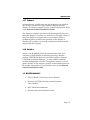
E1100, E2100, AND E3100 SERIES ETHERNET NETWORK ADAPTERS INSTALLATION GUIDE Desktop Network Interface Products C A B L E T R O N S Y S T E M S, I N C. NOTICE NOTICE Cabletron Systems reserves the right to make changes in specifications and other information contained in this document without prior notice. The reader should in all cases consult Cabletron Systems to determine whether any such changes have been made. The hardware, firmware, or software described in this manual is subject to change without notice. IN NO EVENT SHALL CABLETRON SYSTEMS BE LIABLE FOR ANY INCIDENTAL, INDIRECT, SPECIAL, OR CONSEQUENTIAL DAMAGES WHATSOEVER (INCLUDING BUT NOT LIMITED TO LOST PROFITS) ARISING OUT OF OR RELATED TO THIS MANUAL OR THE INFORMATION CONTAINED IN IT, EVEN IF CABLETRON SYSTEMS HAS BEEN ADVISED OF, KNOWN, OR SHOULD HAVE KNOWN, THE POSSIBILITY OF SUCH DAMAGES. Copyright October 1992 Cabletron Systems, Inc. 35 Industrial Way, P.O. Box 5005 Rochester, NH 03867-0505 All Rights Reserved Printed in the United States of America Order number: 9030445-02 October 92 Multi Media Access Center, LANVIEW and Remote LANVIEW are registered trademarks and Desktop Network Interface, E1100, E2100, E3100, FOT-F, LAN-MD, and MMAC are trademarks of Cabletron Systems, Inc. SunNet Manager is a registered trademark of Sun Microsystems, Inc. IBM, IBM Personal Computer AT, Micro Channel, IBM Personal System/2 and PS/2 are registered trademarks of International Business Machines Corporation. IBM Personal Computer XT and PC LAN are trademarks of International Business Machines Corporation. MS-DOS is a trademark of Microsoft Corporation. Novell and NetWare are registered trademarks of Novell, Inc. i FCC NOTICE FCC NOTICE This device complies with Part 15 of FCC rules. Operation is subject to the following two conditions: (1) this device may not cause harmful interference, and (2) this device must accept any interference received, including interference that may cause undesired operation. WARNING: This equipment has been tested and found to comply with the limits for a Class A digital device, pursuant to Part 15 of FCC Rules. These limits are designed to provide reasonable protection against harmful interference when the equipment is operated in a commercial environment. This equipment uses, generates, and can radiate radio frequency energy and if not installed in accordance with the operator’s manual, may cause harmful interference to radio communications. Operation of this equipment in a residential area is likely to cause interference in which case the user will be required at his own expense to correct the interference. If this equipment does cause interference to radio or television, which can be determined by turning the equipment off and on, the user is encouraged to try to correct the interference by one or more of the following measures: • • • • Re-orient the receiving antenna. Relocate the computer with respect to the antenna. Move the computer away from the receiver. Plug the computer into a different outlet so that the computer and the receiver are on different branch circuits. If necessary, the user should consult the dealer or an experienced radio/television technician for additional suggestions. The user may find the following booklet prepared by the Federal Communication Commission helpful: “Interference Handbook” This booklet is available from the U.S. Government Printing Office, Washington D.C. 20402 - Stock No. 004-000-00482-5. ii CONTENTS CONTENTS CHAPTER 1 1.1 1.2 1.3 INTRODUCTION Using This Manual ....................................................................1-1 The Adapter Features ...............................................................1-2 1.2.1 Connectivity ...................................................................1-2 1.2.2 Thin Ethernet Port .........................................................1-2 1.2.3 10BASE-T Twisted Pair Port ........................................1-2 1.2.4 Fiber Optic Ports ............................................................1-3 1.2.5 Jabber Protection ............................................................1-3 1.2.6 LANVIEW LEDs ............................................................1-3 1.2.7 Software ..........................................................................1-5 1.2.8 Statistics ...........................................................................1-5 Related Manuals ........................................................................1-5 CHAPTER 2 INSTALLATION 2.1 Adapter Models .........................................................................2-1 2.1.1 Model Number References ...........................................2-2 2.2 The E1100/E2100 Series Adapters ..........................................2-2 2.2.1 Unpacking the Adapter ................................................2-3 2.2.2 Copying the Software ....................................................2-3 2.2.3 Preparing the E1100 for Installation ............................2-3 2.2.4 Preparing the E2100 for Installation ............................2-4 2.3 Setting the I/O Base Address Jumper ....................................2-5 2.4 I/O Address Space Requirements ..........................................2-6 2.5 Installing a Boot PROM ............................................................2-6 2.6 Installing the E1100/E2100 Adapters .....................................2-7 2.7 Installing the E3100 Series Adapters ....................................2-10 2.7.1 Preparing the E3100 Series for Installation ..............2-10 2.7.2 E3100 Series Boot PROM ............................................2-10 2.7.3 Installing the E3100 Adapter ......................................2-11 2.8 Copying the ADF File .............................................................2-14 2.9 Loading Network Software ...................................................2-14 2.10 Troubleshooting Check List for Adapters ...........................2-15 iii CONTENTS 2.11 Software Check List ................................................................2-15 2.12 Getting Help ............................................................................2-16 2.13 Specifications ...........................................................................2-18 2.13.1 Power Requirements ...................................................2-18 2.13.2 Environmental Requirements ....................................2-18 2.13.3 Safety .............................................................................2-18 2.13.4 Dimensions ...................................................................2-18 CHAPTER 3 3.1 3.2 3.3 3.4 MAKING NETWORK CONNECTIONS Connecting to a Twisted Pair Segment ..................................3-1 3.1.1 RJ-45 Interface (UTP Port) ............................................3-1 3.1.2 Twisted Pair Requirements ..........................................3-3 Connecting to a Thin-net Segment .........................................3-4 3.2.1 BNC Interface (Coax Port) ............................................3-4 3.2.2 Thin-Net Requirements ................................................3-5 Connecting to a Fiber Optic Link Segment ............................3-6 3.3.1 Fiber Optic Requirements .............................................3-7 3.3.2 Fiber Optic Interface (Fiber Optic Ports) ....................3-8 Connecting to an External Transceiver ..................................3-9 3.4.1 AUI Connector (AUI Ports) ..........................................3-9 3.4.2 AUI Interface ................................................................3-10 3.4.3 AUI Cable Requirements ............................................3-10 APPENDIX A ADDRESS/INTERRUPT TABLES INDEX iv INTRODUCTION CHAPTER 1 INTRODUCTION This manual provides installation and reference information for the network adapters. The network adapters connect your PC to: a 10BASE-T twisted pair Ethernet network segment, a thin Ethernet 10BASE-2 coaxial network, a fiber optic network segment, or a transceiver via an AUI cable. The adapters incorporate Cabletron Systems’ LANVIEW LEDs. These diagnostic LEDs indicate power, network transmit and receive, link established, and collision present conditions as soon as the adapter is connected to the network segment. 1.1 USING THIS MANUAL This manual is organized so that you can follow sequential chapters as you install the adapter. Read Chapter 1 first to familiarize yourself with the adapter’s capabilities. Then: • Copy the software diskettes supplied with the adapter. • Install the adapters as outlined in Chapter 2. • Run the diagnostic program supplied with the adapter. • Connect the adapter to the network as outlined in Chapter 3. • Install the network drivers required for your application as outlined in the Network Software Installation Guide. Chapter 1, Introduction, discusses the capabilities of the adapters. Chapter 2, Installation, provides instructions for installing the adapters in your computer. Chapter 3, Making Network Connections, provides instructions and requirements for connecting your adapters to the network. Page 1-1 INTRODUCTION 1.2 THE ADAPTER FEATURES The following sections outline the features of the adapters. 1.2.1 Connectivity The Cabletron Systems adapters connect your computer to an IEEE 802.3 Ethernet network. The various adapter models incorporate either an Ethernet 10BASE-T twisted pair port, a thin Ethernet coaxial BNC port, an SMT type fiber optic port, or an external transceiver via an AUI cable. All port types provide access for SNMP network management such as Cabletron’s SPECTRUM, Remote LANVIEW/Windows, or any SNMPcompliant management software. 1.2.2 Thin Ethernet Port The adapter’s 10BASE-2 port provides a thin Ethernet BNC connection to a coaxial segment such as the backbone of a corporate-wide network, or to a concentrator such as Cabletron’s MMAC Multi Media Access Center. 1.2.3 10BASE-T Twisted Pair Port The adapter’s 10BASE-T twisted pair port employs the RJ-45 eight-pin industry standard connector which must be connected to a concentrator such as Cabletron’s MMAC Multi Media Access Center. The 10BASE-T twisted pair port on the adapter has builtin automatic polarity detection and correction. This means that if the cable connected to the twisted pair port should have the RX+ and RX– leads reversed, the port circuitry will automatically detect and correct this problem. When polarity correction has occurred, the link LED flashes to indicate that this automatic correction has been performed. Performance will not be impacted. Page 1-2 INTRODUCTION 1.2.4 Fiber Optic Ports The fiber optic ports on the adapter employs two ST type fiber optic connectors. The dark gray ST connector is the fiber optic receive port and light gray ST connector is the fiber optic transmit port. The ST connector fiber optic ports can utilize 50/125 µm, 62.5/125 µm, and 100/140 µm fiber optic cables. 1.2.5 Jabber Protection A built-in jabber protection scheme ensures that the network is not disabled due to the transmission of excessively long packets (jabber). This protection scheme automatically interrupts the port for 96 bit times (1 bit time = 100 ns.) if the port has been transmitting continuously for more than 65,536 bit times. 1.2.6 LANVIEW LEDs Cabletron Systems’ adapters incorporate Cabletron Systems’ LANVIEW Status Monitoring and Diagnostic System. The LANVIEW LEDs help you diagnose problems, such as failure to establish a twisted pair link between the adapter and an Ethernet device at the far end of the link. Individual LEDs advise you when the adapter is receiving or transmitting data packets, or when a collision condition exists on the network (see Figure 1-1). • Media Link Good (LNK) LED fiber optic adapters When lit, this green LED indicates that a link has been established between the fiber optic port on the adapter and the fiber optic device at the other end of the fiber optic link segment. This LED remains lit as long as the link is maintained. • Link OK (LNK) 10BASE-T only When lit, this LED indicates that a link has been established between the adapter and the device at the other end of the Ethernet segment (green indicator). Page 1-3 INTRODUCTION XMT CP RCV LNK or PWR CP XMT LNK Upper Port RCV RJ-45 Port RJ-45 Port LNK Lower Port RJ-45 Port BNC Port Dual Media Adapter Dual Port Adapter Figure 1-1. LANVIEW LEDs • Collision Present (CLN) This LED flashes when the adapter is transmitting to indicate that the adapter is detecting a collision condition on the network (red indicator). • Receive (RCV) network traffic This LED flashes to indicate that the adapter is receiving data packets from the network (yellow indicator). • Transmit (XMT) This LED flashes to indicate the adapter is transmitting packets onto the network (green indicator). Page 1-4 INTRODUCTION 1.2.7 Software Software drivers, related software, and diagnostics are supplied by Cabletron Systems on floppy diskettes shipped with the adapter. The drivers support a variety of network platforms. Refer to the Network Software Installation Guide. The diagnostic program provided with the adapter allows you to check the adapter’s operation at various levels, through a series of tests. The diagnostic program allows you to detect where a problem might be located in the operation of the adapter, or determine if a problem exists in the communication between the adapter and the computer. 1.2.8 Statistics Statistics can be gathered from the adapter either from your computer, or from another workstation utilizing Cabletron Systems’ SPECTRUM, Remote LANVIEW/Windows, Remote LANVIEW for SunNet Manager, or other SNMP-compliant network management software. Through this software, you can gather statistics on the adapter’s activity on the Ethernet network. For further information on Local Statistics, refer to the Network Software Installation Guide. 1.3 RELATED MANUALS • TPT-T 10BASE-T Transceiver User’s Manual • Remote LANVIEW/Windows Station Software User’s Manual • SPECTRUM documentation • Network Software Installation Guide Page 1-5 INSTALLATION CHAPTER 2 INSTALLATION 2.1 ADAPTER MODELS The E1100, E2100, and E3100 Series network adapters are used for the specific computer bus architectures listed below: • E1100 Series - IBM Personal Computer XT, IBM Personal Computer AT, IBM Personal System/2 Models 25 or 30, or a compatible with an XT or an AT style bus. • E2100 Series - IBM Personal Computer AT, IBM Personal System/2 Model 30, or a compatible with an AT style bus. • E3100 Series - IBM Personal System/2 or compatibles with a Micro Channel style bus. Each type of adapter is available with a large memory option for use in more demanding network environments. Large memory is indicated by a - X appended to the adapter model number. Table 2-1. Ethernet Adapter Model Number Reference E 21 1 2 -X Topology Bus Type 1st Media 2nd Media Options E- Ethernet 11 - XT 0 - AUI 0 - AUI -X Large Memory 21 - AT 1 - Tw. Pair 1 - Tw. Pair 31 - MC 2 - Coax 2 - Coax 3 - Fiber SMA 3 - Fiber SMA 4 - Fiber ST 4 - Fiber ST 9 - N/A Page 2-1 INSTALLATION 2.1.1 Model Number References The descriptions of Ethernet adapter features use model numbers with a lower case x in them. The x indicates that any number from the model number reference chart applies to that feature. The model number E11xx indicates an E1100 series adapter with any media combination has the described feature. For example, an E1112 is an E1100 Series adapter with UTP and coax ports. A model with the suffix -X indicates a large memory option. The optional memory sizes are listed below: • E1100 Series - 8 KB, E1100-X Series - 32 KB • E2100 Series - 16 KB, E2100-X Series - 64 KB • E3100 Series - 16 KB, E3100-X Series - 64 KB 2.2 THE E1100/E2100 SERIES ADAPTERS This chapter shows you how to prepare an E1100 or E2100 Series Cabletron Systems’ network adapter and install it in your computer. The I/O base address and Boot PROM address are hardware configurable for the E1100 and E2100 Series adapters, while the other parameters are set through software. The preparation and installation procedure for the adapter consists of the following steps: • Unpacking the adapter and software • Making a backup copy of the software • Configuring and installing the adapter • Running diagnostics • Making network connections • Installing network drivers Page 2-2 INSTALLATION 2.2.1 Unpacking the Adapter The network adapter and its software are shipped separately. The complete installation package should contain one conductive pouch with the adapter and this manual. The software is shipped in a shrink-wrapped package containing the software, a license agreement, and a Network Software Installation Guide. Carefully remove the conductive pouch from the box. Leave the adapter in the conductive pouch until you are ready to install it. Open the shrink-wrapped software package when you are ready to install the software. Be sure to read the license agreement. CAUTION: The adapter is sensitive to static discharges. Hold it by the corners. Avoid contact with the PC bus edge connector or any of the components, except the jumpers. Failure to observe all static precautions can result in damage to the adapter. 2.2.2 Copying the Software Before you begin the installation, it is important that you make a backup copy of the Cabletron software supplied with the adapter. Use the disk copy routine for your PC to make a duplicate copy of the Cabletron software diskettes. Store the original software in a safe place, and use the copies for the actual installation procedure. 2.2.3 Preparing the E1100 for Installation The E11xx Series employs a socket for an optional Boot PROM. All parameters except the I/O base address and PROM base address are set through software. Instructions are included for setting the I/O base address, and installing the Boot PROM. Figure 2-1, an E1112 adapter, shows the locations of the jumpers and Boot PROM socket. Boot PROM addressing is covered in the installation instructions included with the Boot PROM. Page 2-3 INSTALLATION Boot PROM Socket JP1 I/O Base Address JP2 ROM Enable Figure 2-1. The E1112 Adapter 2.2.4 Preparing the E2100 for Installation The E21xx Series employs a socket for an optional Boot PROM. All parameters except the I/O base address and PROM base address are set through software. Instructions are included for setting the I/O base address, and installing the Boot PROM. Figure 2-2, an E2112 adapter, shows the locations of the jumpers and Boot PROM socket. Boot PROM addressing is covered in the installation instructions included with the Boot PROM. Boot PROM Socket JP1 I/O Base Address JP2 ROM Enable Figure 2-2. The E2112 Adapter Page 2-4 INSTALLATION 2.3 SETTING THE I/O BASE ADDRESS JUMPER The I/O base address Jumper, JP1, must be set to one of four possible addresses before the adapter is installed. The I/O base address jumper sets the I/O (input/output) base address that identifies the adapter to the PC. The I/O base address is a hexadecimal field that distinguishes the adapter from other adapters that may be in the PC. Two shunts are supplied with the jumper in the event you want to use the 220 address setting. Figures 2-1 and 2-2 show the JP1 jumper’s location. To set the I/O base address jumper, JP1 (Figure 2-3), hold the adapter so the components are facing you and the ports are on your right. 1 2 3 4 Figure 2-3. JP1, E1100/E2100 I/O base address Jumper Pins 220 280 300 380 Figure 2-4. I/O Base Address Settings Select one of four possible I/O base addresses by placing shunts on the JP1 pins as shown in Figure 2-4. Note that address 220 requires the use of both shunts. No shunts are required for the default address 380. Page 2-5 INSTALLATION 2.4 I/O ADDRESS SPACE REQUIREMENTS The I/O address space for the E1100 and E2100 Series adapters occupies 20 Hex of the selected I/O base address. For example, if you select 220 Hex, the adapter I/O address range will extend through 23F Hex. Note that 23F lies within the address space (230 to 240) allotted to the bus mouse. If your system uses a bus mouse, address 220 cannot be used for the adapter because of the address conflict with the bus mouse. Appendix A, Address/Interrupt Tables, lists the I/O addresses of commonly used devices. 2.5 INSTALLING A BOOT PROM The E1100 and E2100 Series adapters have a socket for an optional Boot PROM. The Boot PROM plugs into the empty 28-pin socket shown in Figures 2-1 and 2-2. By installing a Boot PROM, you can use the adapter to boot up your PC, without a hard drive, onto a network running, for example, the Novell NetWare network operating system. A Boot PROM address jumper (JP2) must be set before the Boot PROM can be used, however. Figure 2-5. Boot PROM and Socket Alignment CAUTION: Observe all precautions when handling the Boot PROM. Static discharges may damage the Boot PROM. Page 2-6 INSTALLATION To install a Boot PROM, remove the Boot PROM from its packaging. Ensure that the legs of the Boot PROM are aligned in a 90° angle with the PROM body so the legs of the Boot PROM are perpendicular to the Boot PROM pin sockets. Insert the Boot PROM into the PROM socket so that the notch in the PROM is aligned with the notch in the socket as shown in Figure 2-5. Refer to the Boot PROM installation instructions included with the PROM for setting Boot PROM parameters. Refer to your PC user manual for further information on selecting a Boot PROM address for your application. 2.6 INSTALLING THE E1100/E2100 ADAPTERS Note that any of the E1100 and E2100 Series adapters can be installed in either an XT or an AT style expansion slot. The E1100 adapter will occupy the forward half of the bus connector in an AT style bus. CAUTION: The adapter is sensitive to static discharges. Hold it by the corners. Avoid contact with the PC bus edge connector or any of the components, except the jumpers. Failure to observe all static precautions may result in damage to the adapter. Follow these steps to install the adapter in your computer: • Turn off the power to the PC and peripherals and disconnect all power cords and cables. • Following the instructions in your computer user manual, using static discharge precautions, remove the cover from the computer. • Select the slot in which the adapter will be installed. An E1100 adapter can occupy any XT style, 8-bit expansion slot, or an AT style, 16-bit expansion slot. An E2100 can occupy any 16-bit expansion slot or an XT type slot, but in an 8-bit slot, performance will be degraded. Page 2-7 INSTALLATION • Carefully remove the adapter from its protective pouch, and visually inspect it. • Remove the backplate (2, Fig. 2-6) from the selected slot (3) by removing the screw (1) holding the backplate in place, and sliding the backplate out of the slot as shown in Figure 2-6. Carefully insert the adapter into the expansion slot as shown in Figures 2-7 and 2-8. Orient the adapter (1) so the PC edge bus connector (2) is pointed down and the ports face out the back of the PC. Align the adapter so the PC bus edge connector is lined up with the expansion slot (3), and firmly press, but do not force, the adapter into the slot. 1 3 2 1. Screw 2. Backplate 3. Expansion Slot Figure 2-6. Backplate Detail Page 2-8 INSTALLATION 1 1. Adapter 2. PC Board Connector 3. Expansion Slot 2 3 Figure 2-7. Installing the E1100 Series Adapter 1 1. Adapter 2. PC Board Connector 3. Expansion Slot 2 3 Figure 2-8. Installing the E2100 Series Adapter Page 2-9 INSTALLATION Reinsert the screw removed in disassembly and replace the PC cover. Reattach the power and peripheral cables and turn on the power for the PC and the peripherals. 2.7 INSTALLING THE E3100 SERIES ADAPTERS This section contains instructions for preparing and installing your Cabletron Systems E3100 Series network adapter into your computer. The only hardware preparation for installing the E3100 Series adapter is the installation of an optional Boot PROM. 2.7.1 Preparing the E3100 Series for Installation The parameters for the E3100 Series adapters are set when the Adapter Description File (ADF) is configured. The ADF file distinguishes the adapter from other boards in the computer. The ADF will be configured after the adapter is installed. CAUTION: The adapter is sensitive to static discharges. Hold it by the corners. Avoid contact with the PC bus edge connector or any of the components. Failure to observe all static precautions may result in damage to the adapter. 2.7.2 E3100 Series Boot PROM The E3100 Series adapters each have a socket for an optional Boot PROM, which is purchased separately. By installing a Boot PROM, you can use the adapter to boot up your PC, without a hard drive, onto a network running for example, the Novell NetWare network operating system. The Boot PROM is configured with the necessary parameters when configuring the Adapter Description File, as described in Section 2.8. Refer to Figure 2-9 for the location of the Boot PROM socket. See Boot PROM installation instructions included in Section 2.5. An E3112 is shown in Figure 2-1. CAUTION: Observe all precautions when handling the Boot PROM. Static discharges may damage the Boot PROM. Page 2-10 INSTALLATION Boot PROM Socket Figure 2-9. The E3112 Adapter 2.7.3 Installing the E3100 Adapter To install the adapter in your computer, follow these instructions: • Turn off the power to the PC and peripherals and disconnect all power cords and cables. • Following the instructions in your computer user manual, using static discharge precautions, remove the cover from the computer. • Select the slot in which the adapter will be installed. Your adapter can occupy any unused Micro Channel style, 16-bit or 32-bit expansion slot. Page 2-11 INSTALLATION 1 2 1. Backplate 2. Thumbscrew Figure 2-10. Micro Channel Backplate Detail CAUTION: The adapter is sensitive to static discharges. Hold it by the corners. Avoid contact with the PC bus edge connector or any of the components. Failure to observe all static precautions may result in damage to the adapter. • If you have not already done so, carefully remove the adapter from its protective pouch, and visually inspect it. • Remove the protective backplate (1, Fig. 2-10) from the selected slot, as shown in Figure 2-10. Loosen the thumbscrew (2) holding the backplate (1) in place over the selected slot, and slide the backplate out of the slot. • Orient the adapter (2, Figure 2-11) so the PC edge bus connector (3) is pointed down and the ports face out the back of the PC as shown in Figure 2-11. Page 2-12 INSTALLATION • Align the adapter so the PC bus edge connector is lined up with the expansion slot (4) as shown in Figure 2-11. 1 5 2 3 4 1. 2. 3. 4. 5. Clip Adapter Edge Connector Expansion Slot Clip Figure 2-11. Installing the E3100 Series Adapter • Slide the adapter into the guide slots and firmly press, but do not force, the adapter into the expansion slot. The plastic clips on the adapter (1, 5, Figure 2-11) will snap into place as the adapter is inserted into the expansion slot. • Reinsert the thumbscrew, and replace the PC cover. Reattach the power and peripheral cables, and power up the PC. Page 2-13 INSTALLATION 2.8 COPYING THE ADF FILE After an E3100 Series adapter is installed in your computer and before using it, you must copy the Cabletron Adapter Description File (ADF) onto a backup copy of your system’s Reference Diskette. The ADF is supplied with your Cabletron software. The ADF provides Programmable Option Select Parameters for the System Configuration Utility. If necessary, you can change the parameters during this procedure. IMPORTANT: Be sure to use a backup copy of the Reference diskette, and not the original Reference Diskette, when you perform the following procedure. To configure the ADF: • Copy the two ADF Files from the Cabletron diskette to IBM’s Reference Diskette (@ 5608.adf and @ 5609.adf). • Boot from the IBM Reference Diskette. • Answer Yes to: Automatically configure the system? 2.9 LOADING NETWORK SOFTWARE You must install the proper network software in order to use your PC, with an adapter, on an Ethernet network. Network operating system software drivers are supplied on the Cabletron software diskettes that are shipped with the adapter. The drivers are grouped in subdirectories that contain readme files (a .DOC extension) to explain any recent changes in procedure, etc. The Network Software Installation Guide, included with the software, contains detailed installation instructions for installing network drivers. Page 2-14 INSTALLATION 2.10 TROUBLESHOOTING CHECK LIST FOR ADAPTERS • Make sure the adapter is installed and properly seated in the PC chassis connector. • On the adapter, if the coax port is used it is necessary to have a T and terminator attached to it. • If the adapter does not initialize, verify that the bus slot is operational by swapping the adapter with an adapter that you know is functioning. • Try swapping the adapter with a known working adapter. • The interrupt, I/O address or memory parameters could be conflicting with another adapter. Use a program like “CheckIt” to determine what settings are currently in use by other adapters. • Verify that the cable is attached to the media port that you want to use. • If a connection to a server or another host cannot be maintained, check the cable first with a TDR or pair scanner. After verifying the cable, check the device that you are trying to communicate with. Verify that you can ping it or that other clients can contact it. 2.11 SOFTWARE CHECK LIST • Cabletron supplies different drivers for use with different operating systems. Make sure that you are using the correct driver and that the I/O hardware jumper agrees with the software I/O setting that you selected. • If you are using Novell NetWare, Cabletron supplies a direct IPX and a packet driver IPX. Make sure you are using the correct IPX.COM file. Page 2-15 INSTALLATION • The adapters use shared memory. VGA adapters will use the A block through C7FFF. Memory adapters will use the entire D block. If you don’t have a memory adapter installed, the D block is your best selection - otherwise the C8000 starting address can be used on the standard memory adapters. • If Windows is installed on an Ethernet client, then it is necessary to modify the SYSTEM.INI File. See the Network Software Installation Guide. • When using the packet driver version 4.0 or above, you must use IPX (NSHPD) LAN Option 1.05.03 or above. • If you are using a Kingston Memory Board, DO NOT use automatic configuration after copying the Cabletron ADF file. 2.12 GETTING HELP If you need additional support related to the adapter, or if you have any questions, comments, or suggestions concerning this manual, contact Cabletron Systems Technical Support. Before calling, please have the following information available for use by the Cabletron Technical Support personnel who will assist you. • The Adapter type and Serial Number (i.e., E2112, E1192070111). • The software version that appears on the front of the installer diskettes (i.e., E2100 Version 3.10.00, Rev. XX, P/N 2160251). • Your computer make, model, and CPU type (i.e., IBM PS/2 Model XX, Intel 80X86, etc.). • The operating systems and versions you are using (i.e., MS DOS Version 5.0, and Novell NetWare Version 3.11). • The make and model of any other add-in adapters you are using in your system and their bus address, interrupt settings, and memory allocation. Page 2-16 INSTALLATION • The contents of the AUTOEXEC.BAT, CONFIG.SYS, PROTOCOL.INI, and NET.CFG files (if applicable). You can contact Cabletron Systems Technical Support by: Phone: (603) 332-9400 FAX: (603) 335-4743 BBS: (603) 335-3358 (4 lines available) Cabletron Technical Support can also be reached over the Internet by sending email to: [email protected] Drivers are available for anonymous FTP download from: ctron.com (IP Address 134.141.197.25) CompuServe subscribers can also contact Cabletron Technical Support through the Cabletron Forum by entering: GO CTRON at any ! prompt. If you have any questions, comments, or suggestions concerning this manual, you can write to Cabletron Systems Technical Support at: Cabletron Systems, Inc. 35 Industrial Way, P.O. Box 5005 Rochester, NH 03867-0505 Page 2-17 INSTALLATION 2.13 SPECIFICATIONS 2.13.1 Power Requirements E1100 Series +5 V @ ≤ 2.0 amps maximum +12 V @ ≤ 500 mA maximum with transceiver attached. E2100 Series +5 V @ ≤ 2.0 amps maximum +12 V @ ≤ 175 mA maximum with transceiver attached. E3100 Series +5 V @ ≤ 1.2 amps maximum +12 V @ ≤ 175 mA maximum with transceiver attached. 2.13.2 Environmental Requirements Operating Temperature: 0° to + 60°C (32° to 140°F) Operating Humidity: 10% to 90% (non-condensing) 2.13.3 Safety Designed in accordance with UL478, UL910, NEC 725-2(b), CSA, IEC, TUV, VDE Class A. Meets FCC, Part 15, Class A limits. 2.13.4 Dimensions E1100 Series 7.9 H x 11.4 W cm (3.1 H x 4.5 W inches) E2100 Series 7.9 H x 16.8 W cm (3.1 H x 6.6 W inches) E3100 Series 8.8 x 20.4 cm (3.5 x 8.0 inches) Page 2-18 MAKING NETWORK CONNECTIONS CHAPTER 3 MAKING NETWORK CONNECTIONS This section contains instructions for connecting your adapter to an Ethernet network. An adapter can be connected to the network through either a media interface port or an AUI port on the adapter. You should have selected the port during the configuration procedures. If you did not, refer to the appropriate section for your adapter. We recommend that you run the diagnostic program before connecting your PC to a network segment. You can run the diagnostic program from the Cabletron installer program on the Cabletron software diskettes. NOTE: If you run the diagnostic program, be sure to perform a soft (warm) boot on your PC before continuing. 3.1 CONNECTING TO A TWISTED PAIR SEGMENT 3.1.1 RJ-45 Interface (UTP Port) 1. Wire Fault Attachment LED 2. RJ-45 Port 3. RJ-45 Connector 4. Unshielded Twisted Pair Link 1 2 3 4 Figure 3-1. Attaching a UTP Segment Page 3-1 MAKING NETWORK CONNECTIONS 12 3 4 5 6 7 8 RJ-45 Port RJ-45 Connector Figure 3-2. RJ-45 Connector RJ-45 Connections Type: Pin 1 2 3 4 TX+ TXRX+ No Connection RJ-45 connector Pin 5 6 7 8 No Connection RXNo Connection No Connection • Connect the twisted pair segment (4, Fig. 3-1) by inserting the RJ-45 connector (3) into the adapter’s RJ-45 port (2). • Check that the Link LED on the adapter is lit. The Link LED may not light until data has been transmitted out the 10BASE-T port. If you know the adapter has attempted to transmit data and the LED is not lit, check the items listed here: • Verify that the power is on for the PC. • Check that the 10BASE-T device at the other end of the twisted pair segment is powered up. • Verify that the RJ-45 connector on the twisted pair segment has the proper pinouts (see Figure 3-2, above). Page 3-2 MAKING NETWORK CONNECTIONS • Check the cable for continuity, and ensure that the cable is actually a twisted pair cable. • Check that the adapter is properly seated in the expansion slot. • Check that the twisted pair connection meets dB loss and cable specifications outlined in Section 3.1.2, below. If a link still has not been established, contact Cabletron Systems Technical Support (see Section 2.12, Getting Help). 3.1.2 Twisted Pair Requirements • Length - 10BASE-T transceivers must be able to transmit over a 100 meter link (328 feet) using 24 AWG unshielded twisted pair wire. 10BASE-T specifies no maximum link length. NOTE: Due to cable delay, the maximum link length is always limited to about 200 meters (656 feet), regardless of the cable type. Generally, links up to 150 meters (492 feet) long are achievable for unshielded and shielded twisted pair cable. For each connector or patch panel, subtract 12 meters (39.4 feet). This allows links of up to 126 meters (413.4 feet) using standard 24 AWG UTP wire and two patch panels. Higher quality, low attenuation cables may be required when using links greater than 126 meters. • Insertion Loss - 11.5 dB maximum for a 10BASE-T link at all frequencies between 5.0 and 10.0 MHz. This includes attenuation of cables, connectors, patch panels, and reflection losses due to impedance mismatches. • Impedance - Unshielded twisted pair cable is typically between 85 to 110 ohms. Shielded cable, such as Type 1 cable, is typically 150 ohms which can increase the signal reflection. Cabletron Systems 10BASE-T Twisted Pair products will work on shielded twisted pair cable with 75 to 165 ohms impedance. • Jitter - Not more than 5.0 nsec for a 10BASE-T link. Page 3-3 MAKING NETWORK CONNECTIONS • Delay - Must not exceed 1000 nsec for a 10BASE-T link. This delay limits maximum link segments to 200 meters. • Crosstalk - Crosstalk is caused by signal coupling between cable pairs within a multi-pair cable bundle. Crosstalk should not be a problem if the cable meets all other requirements. • Noise - Noise can be caused by either crosstalk or externally induced impulses. Impulse noise may cause data errors if the impulses occur at very specific times during data transmission. If noise related data errors are suspected, it may be necessary to reroute the cable or eliminate the source of the impulse. • Temperature - Multi-pair, PVC 24 AWG telephone cables have an attenuation of approximately 8 to 10 dB/100 m at 20°C. The attenuation of PVC insulated cable varies significantly with temperature. At temperatures greater than 40°C, we strongly recommend that you use plenum rated cables to ensure that cable attenuation remains within specification. 3.2 CONNECTING TO A THIN-NET SEGMENT To connect a thin coaxial 10BASE-2 segment to an adapter with a BNC port, attach a BNC tee-connector (2, Figure 3-3) to the adapter’s BNC port (1, Figure 3-3). Next, attach the thin-net segment (3, Figure 3-3) to one of the male connectors on the teeconnector. Each segment attached to the tee-connector must be terminated. If a segment is not attached to one of the male connections on the tee-connector, then a terminator (5, Figure 3-3, View A) must be placed on that connection. Attach another thin-net segment (4, Figure 3-3, View B) or a terminator (5, View A) to the other male connector on the tee-connector. 3.2.1 BNC Interface (Coax Port) BNC receptacle with gold center contact, for use with BNC type tee-connectors and RG-58 cable. Page 3-4 MAKING NETWORK CONNECTIONS 1 3 2 1 3 2 5 View A 4 View B Figure 3-3. Attaching a Thin-Net Segment 3.2.2 Thin-Net Requirements • Cable - Must be 50 ohm RG-58A type coaxial cable. • Length - Must be no longer than 185 meters (607 ft.). • Termination - A 50 ohm terminator at the far ends of each thin-net segment. • Connections - A maximum of 30 connections may be used throughout a thin coaxial segment for host connections. If an excessive number of barrel connections are used within the cable segment, i.e. finished wall plates with BNC feedthroughs, then a reduced number of host connections may be required. For special network designs, contact Cabletron Systems Technical Support. WARNING: For safety, only one end of a thin-net segment should be connected to earth ground. Connection to earth ground at more than one point on the segment may allow for the occurrence of dangerous ground currents. Page 3-5 MAKING NETWORK CONNECTIONS 3.3 CONNECTING TO A FIBER OPTIC LINK SEGMENT The physical communication link consists of two fiber optic strands between the adapter and the other Ethernet fiber optic device on the link: Transmit (TX) and Receive (RX). The adapter Tx connects to Rx of the Ethernet device. The adapter Rx connects to Tx of the Ethernet concentrator. We recommend that you label the fiber optic cable to indicate which fiber is Receive and which is Transmit. When you buy fiber optic cable from Cabletron Systems, it is labeled so that at one end of the cable, one fiber is labeled 1, and the other fiber is labeled 2. This pattern is repeated at the other end of the cable. ST connectors (Figure 3-4) attach to ST ports in the same way that BNC connectors attach to BNC ports. The connector is inserted into the port with an alignment slot on the connector inserted into the alignment key on the port. The connector is then turned until it is locked. NOTE: Do not touch the ends of the fiber optic strands and do not let the ends come in contact with dust, dirt, or other contaminants. Contamination of the ends can cause data transmission problems. If the ends become contaminated, clean them with denatured alcohol using a soft, clean, lint free cloth. If this does not work, use a fiber optic polishing kit to polish the end of the strand. To connect to a fiber optic segment, attach the fiber labeled 2 to the adapter’s transmit port (light gray) (1). At the other end of the fiber optic cable, attach the fiber labeled 1 to the transmit port of the applicable device. Attach the fiber labeled 2 to the receive port of the fiber optic device. At this time you should check to see that the adapter’s Link LED is lit. If the LED is not lit, verify that the power is on for the PC, and check that the power is turned on for the device at the other end of the fiber optic link. Page 3-6 MAKING NETWORK CONNECTIONS Verify that the fiber strands are “crossed over” at the far end device, transmit to receive, by checking the labeling on each strand. Verify that the fiber connection meets the dB loss specifications outlined in Section 3.3.1, below. If a link still has not been established, contact Cabletron Systems Technical Support (see Section 2.12, Getting Help). 1 2 1. ST Port 2. ST Connector Figure 3-4. ST Fiber Optic Connectors 3.3.1 Fiber Optic Requirements • Cable - The fiber optic link segments should consist of either 50/125 µm, 62.5/125 µm, or 100/140 µm fiber optic cabling. • Attenuation - Cable must be tested with a fiber optic attenuation test set adjusted for an 850 nm wave length. This test verifies that the signal loss in the cable is acceptable. Attenuation limits for various cable are listed below: - 13.0 dB or less for a 50/125 µm fiber cable segment. - 16.0 dB or less for a 62.5/125 µm fiber cable. - 19.0 dB or less for a 100/140 µm fiber cable. • Fiber Optic Budget - the fiber optic budget and total network propagation delay should be calculated before fiber runs are incorporated in any network design. Fiber optic budget is the combination of optical loss of the fiber optic cable, in-line splices, and fiber optic connectors. Propagation delay is the time it takes a packet to travel from the sending device to the receiving device. Page 3-7 MAKING NETWORK CONNECTIONS • Length - The maximum fiber optic cable length is 2 km (6558 feet), if system budgets are met. However, IEEE 802.3 FOIRL (Fiber Optic Inter-Repeater Link) specifications specify a maximum of 1 km (3279 feet). 3.3.2 Fiber Optic Interface (Fiber Optic Ports) Ex040 and Ex040-X: Parameter Receive Sensitivity: ST fiber optic ports Typical Value Worst Case -30.5 dBm -28.0 dBm Peak Input Power: -7.6 dBm -8.2 dBm Worst Case Budget — Typical Budget — — 13.0 dB 16.0 dB 19.0 dB 17.5 dB 20.5 dB 23.5 dB — Transmitter Power: 50/125 µm fiber: -13.0 dBm -15.0 dBm 62.5/125 µm fiber: -10.0 dBm -12.0 dBm 100/140 µm fiber: -7.0 dBm -9.0 dBm Error Rate: Better than 10-10 bit error rate. NOTE: The transmitter power levels and receive sensitivity levels given above are Peak Power Levels after optical overshoot. A Peak Power Meter must be used to correctly compare the values given above to those measured on any port. If Power Levels are measured with an Average Power Meter, add 3 dBm to the average power measurement to correctly compare average power values to the peak power values. Page 3-8 MAKING NETWORK CONNECTIONS 3.4 CONNECTING TO AN EXTERNAL TRANSCEIVER 3.4.1 AUI Connector (AUI Ports) 1 2 3 4 1. Wire Fault/Attachment LED 2. AUI Port 3. AUI Connector 4. Screws (2) Figure 3-5. Connecting an AUI Cable Any adapter with an AUI Port can be connected to the network via a transceiver and an AUI cable. The AUI port should have been selected during the installation procedure. To connect an AUI cable to your adapter, attach an external transceiver to the network segment to which the adapter will be attached. Refer to the applicable transceiver manual. Attach the female end of an AUI cable, no more than 50 meters in length, to the transceiver. Attach the male connector (3, Figure 3-5) on the AUI cable to the adapter’s AUI port (2) and tighten the securing screws (4). Page 3-9 MAKING NETWORK CONNECTIONS 3.4.2 AUI Interface Type: Pin 1 2 3 4 5 6 7 8 15 position D type receptacle Logic Ground Collision + TX + Logic Ground RX + Logic Ground No Connection Logic Ground Pin 9 10 11 12 13 14 15 Shell Collision TX Logic Ground RX Power (+12 Vdc) Logic Ground No Connection Protective Ground 3.4.3 AUI Cable Requirements • Type - The AUI cable connecting the adapter to a transceiver must be Ethernet Version 1, Version 2, or IEEE 802.3, 10BASE-5 type cable that matches the device attached to the AUI port. • Length - The AUI cable must not exceed 50 meters (164 feet) if 24 AWG AUI cable is used. If 28 AWG AUI cable is used, then the maximum cable length is 16 meters (52 feet). Page 3-10 ADDRESS/INTERRUPT TABLES APPENDIX A ADDRESS/INTERRUPT TABLES Table A-1. I/O Ports of Common Devices Possible I/O Base Address 200 Potential Conflicting Devices and Their Typical I/O Addresses Game Controller/Joystick (200 - 20F) Expansion Unit (210 - 217) 220 Cabletron Adapter 230 Bus Mouse 240 260 LPT2:(278 - 27F) 280 Cabletron Adapter 2A0 2C0 2E0 COM4: (2E8 - 2EF) GPIB-Adapter 0 (2E1) COM2: (2F8 - 2FF) Data Aquisition (2E2 - 2E3) 300 Cabletron Adapter 320 XT Hard Disk Interface (320 - 32F) 340 360 LPT1: (378 - 37F) SLDC/Secondary Bi-Sync Interface (380 - 38C) 380 Cabletron Adapter 3A0 Primary Bi-Sync Interface (3A0 - 3A9) Monochrome Display (3B0 - 3BB) 3C0 EGA Display Control (3C0 - 3CF) Color/Graphics Display-CGA (3D0 - 3DF) 3E0 COM3: (3E8 - 3EF) Floppy Disk Controller (3F0 - 3F7) COM1: (3F8 - 3FF) Page A-1 ADDRESS/INTERRUPT TABLES Table A-2. Commonly Used PC Interrupts IRQ Interrupt Usage Machine Type IRQ2 Reserved PC IRQ2 Cascade from slave 8259A PIC AT, PS/2 IRQ3 Serial communications (COM2) PC, AT, PS/2 IRQ4 Serial communications (COM1) PC, AT, PS/2 IRQ5 Fixed disk PC IRQ5 Parallel printer (LPT2) AT IRQ6 Floppy disk PC, AT, PS/2 IRQ7 Parallel printer (LPT1) PC, AT, PS/2 IRQ9 Software diverted to IRQ2 AT, PS/2 IRQ10 Reserved AT, PS/2 IRQ11 Reserved AT, PS/2 IRQ12 Reserved AT IRQ12 Mouse PS/2 IRQ14 Fixed-disk controller AT, PS/2 IRQ15 Reserved AT, PS/2 Page A-2 INDEX INDEX A G adapter features 1-2 10BASE-T port 1-2 connectivity 1-2 fiber optic ports 1-3 jabber protection 1-3 thin Ethernet port 1-2 adapter models 2-1 see table 2-1 2-1 E1100/E2100 series 2-2 installation 2-1 model number references 2-2 preparing the E1100 for installation 2-3 preparing the E2100 for installation 2-4 address/interrupt tables A-1 see table A-1 A-1 see table A-2 A-2 ADF file copying 2-14 getting help 2-16 E external transceiver 3-9 AUI cable requirements 3-10 AUI connector (AUI ports) 3-9 AUI interface 3-10 connecting to 3-9 see figure 3-5 3-9 LANVIEW LEDs 1-3 Collision Present (CLN) 1-4 Link OK (LNK) 1-3 Media Link Good (LNK) LED 1-3 Receive (RCV) 1-4 see figure 1-1 1-4 Transmit (XMT) 1-4 F M fiber optic link segment 3-6 connecting to 3-6 fiber optic budget 3-7 fiber optic interface (fiber optic ports) 3-8 fiber optic requirements 3-7 making network connections 3-1 BNC interface (coax port) 3-4 connecting to a twisted pair segment 3-1 RJ-45 interface (UTP port) 3-1 thin-net requirements 3-5 twisted pair requirements 3-3 I I/O address space requirements 2-6 installing a Boot PROM 2-6 installing the E1100/E2100 adapters 2-7 see figure 2-7 2-9 see figure 2-8 2-9 installing the E3100 Series adapters 2-10 E3100 Series Boot PROM 2-10 installing the E3100 Adapter 2-11 preparing the E3100 Series for installation 2-10 see figure 2-11 2-13 L Index-1 INDEX N network software loading 2-14 R related manuals 1-5 S see table A-2 A-2 setting the I/O base address jumper 2-5 software 1-5 software check list 2-15 specifications 2-18 dimensions 2-18 environmental 2-18 power requirements 2-18 safety 2-18 statistics 1-5 T thin-net segment connecting to 3-4 troubleshooting check list for adapters 2-15 Index-2