1
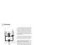
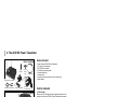
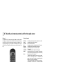
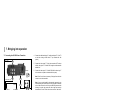
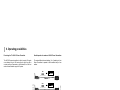
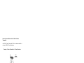
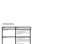
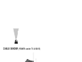
CABLE SENDER (POWER sender TV AVS815)
Thank you very much.
You have acquired an electronic system of a very high technical
standard. With the TV AVS 815 Power Transmitter you can
transmit colour images with stereo sound through walls and
ceilings.
The greatest possible care is necessary for bringing it into
operations, and that means studying every point in these
operating instructions.
Please read these operating instructions even if a third party has
already installed the system because they contain important
information and the basic principles of operation.
We would not expect any problems to arise with the system, but
if any should occur please inform the dealer from whom you
acquired this device.
Please keep this instructions ready to hand whenever you may
need to consult them.
20
Contents
1.
2.
3.
4.
5.
6.
7.
Safety instructions
General description
Transmissions
The AVS 850 Power Transmitter
The AVS 840 Power Transmitter
The RC 815 infra-red remote control for the cable tuner
Bringing into operation
7.1 Connecting the AVS 850
7.2 Connecting the AVS 840
7.3 Adjusting the cable tuner in the AVS 850
7.4 Changing the coding of the RC 815 remote control unit
8. Operating possibilities
9. Rectifying a malfunction
10. Technical data
Page
22
22
23
24
26
28
29
29
30
32
32
34
36
37
21
1. Safety instructions
IMPORTANT
If the system is handled incorrectly there is a risk of injury
from electric shock. The following instructions must be
followed, in order to avoid any risk of injury or damage,
and the operating instructions must also be adhered to.
-
-
-
-
22
It is never allowed to open the plug-in mains adapter
Only a properly qualified technician is allowed to check and
inspect the system.
The system is only ever to be operated in dry, indoor rooms.
Avoid high atmospheric humidity and extreme ambient
temperatures
Should any fault occur in the power supply the system should
be taken out of operation at once. Never replace defective
parts with anything other than original spare parts.
If there is any danger of a thunderstorm, it is a good
precaution to separate the system from the mains network in
order to protect it from lightning. The same applies if the
system is to be out of action for any length of time.
Power must be supplied at the correct rating at all times. This
applies in particular to the operating voltage in the system
and the mains adapter.
If there is ever any malfunction, the dealer from whom the
system was acquired must be asked to send it back to the
manufacturer for inspection.
2. General description
Correct and proper use
The TV AVS 815 Power Transmitter is designed for use in dry, indoor
rooms. The power supply is provided by the mains adapter enclosed with
the Transmitter. Please only ever use this mains adapter.
It is not allowed to alter or modify any part of the system.
The unit is registered as a device that does not cause or suffer radiofrequency interference, it is CE-approved, and it conforms with the Low
Voltage Directory.
The safety and installation instructions must be observed.
There shall be no guarantee cover against damage resulting from any
failure to observe these operating instructions, and no legal liability for
any resultant consequential damage.
General functions
With the TV AVS 815 Power Transmitter you can transmit cable television
signals, and signals from other video equipment such as VCR, SATreceivers, and video cameras by radio.
The audio and video signals are transmitted in the 2.4 GHz range by the
AVS 815 Power Transmitter to the AVS 840 Power Receiver. The
maximum line-of-sight range is 300 metres.
The cable tuner integrated into the AVS 850 Power Transmitter is
controlled by the Power Receiver with the enclosed RC 815 infra-red
remote control. If you point the remote-control unit in the direction of the
infra-red window on the AVS 840 receiver, the infra-red signals from this
remote-control unit will be converted into radio signals which will in turn
be transmitted in the 433 MHz range to the AVS 850 Power Transmitter.
Inside the AVS 850, the radio signals are converted back into infra-red
signals and passed on to the integral cable tuner.
3. Transmissions
Cabel-TV
SAT-TV
1st television set
AVS 850 Transmitter
AVS 840 Receiver
If you use the infra-red remote control of another piece of video
equipment, these infra-red signals will be passed on via the RX 579 infrared module to the relevant appliance, such as a satellite-receiver, the
audio and video signals of which are being transmitted. In order to allow
this equipment, e.g. the satellite receiver, to be controlled via the remote
control to select programmes, the infra-red transmitter on the infra-red
module must be glued onto the infra-red receiver of the equipment that
is being remote-controlled.
When it is being glued on, attention must be paid to ensuring that the
"infra-red eye” of the unit is not completely covered over, so as to ensure
that direct control with the original remote-control unit is still possible.
The extension module possesses two infra-red diodes for controlling two
different units, e.g. a satellite received and a video-recorder.
Establish the position of the infra-red receiver with the aid of the
operating instructions for the unit that is to be controlled; if it is not
possible to locate it exactly, a little trial-and-error will be necessary. You
will thus have the possibility of controlling the unit, the signals of which
are to be transmitted, with the standard remote-c.
2nd television set
23
4. The AVS 850 Power Transmitter
Aerial
adapter
Items included
Items included
Co-axial
branch
plug
1
1
1
1
1
1
1
1
Co-axial cable
AVS 850 Power Transmitter
RX 579 infra-red module
Plug-in mains adapter
Cinch/Scart
connecting cable
Control elements
Control elements
12
1
2
3
4
5
6
Power Sender AVS 850 Power Transmitter
12 V plug-in mains adapter
RX 579 infra-red module
Cinch/Scart connecting cable
co-axial branch plug
co-axial cable
co-axial infra-red remote-control unit for cable tuner
aerial adapter
7
1,433 MHz aerial
Receives the 433 MHz signals of the original remote-control unit
sent by radio from the AVS 840 Power Transmitter and passes
them on to the integrated cable tuner. The infra-red remotecontrol signals are also passed on via the enclosed infra-red
module to the connected item, such as a video-recorder. The
aerial must be placed upwards when the unit is in operation.
10
Rear side
8
24
9
11
2. Socket for RX 579 extension module
For connecting the RX 579 extension module, which remotecontrols the transmitter. The infra-red diode on the extension
module must be glued over the infra-red eye of the item being
controlled. Please note Point 3 here.
3. Channel switch
10. AV cinch output sockets
The channels can either be selected one behind the other (1,2,3,4,1,2,
etc., or the other way round) or set by means of the enclosed infra-red
remote-control unit (using the keys TXA ... TXD – see Point 5).
1 video, 2 audio output sockets. These transmit the cable channel that
has been set, or the signal from the video input. This depends on the
setting of the mode button (5) and the remote control unit (see Point 5).
4. TV channel selection switch
11. Aerial input socket for cable television
The TV channels can be selected with this switch.
For connection to the cable television socket. For connecting, use the
enclosed adapter and the co-axial cable.
5. Mode switch
It is possible to switch from TV to cable TV and video input.
12. 2.4 GHz transmission aerial
Transmits the cable or AV signal to the selected channel.
6. On / Off switch
This is for switching the video transmitter on and off. When the video
transmitter is on, LED 7 will light up.
7. LED display
This lights up when the transmitter is in operation.
8. Connecting socket for the mains adapter
This is for connecting the mains adapter.
9. A/V cinchinput sockets
1 video, 2 audio input sockets for feeding in the transmission signals.
With adapter cables (2 are included with the system) it is possible to
connect almost any item of equipment.
Note: for audio transmissions, it is usual to
use a cinch/cinch cable. These are readily
available in the trade (see picture).
25
5. AVS 840 Power Receiver
Items included
Items included:
1 Power AVS 840 Power Receiver
1 9 V plug-in mains adapter
1 Cinch/scart connecting cable
AVS 840 Power Receiver
Plug-in mains adapter
Control elements
Cinch/scart
connecting cable
Control elements
5
Rear side
1. A/V Cinch output sockets
1 video, 2 audio output sockets. These take the received signal
and feed it into the receiving unit via the appropriate adapter
cable. With adapter cables (2 cinch / scart cables are included
with the system) it is possible to connect almost any item of
equipment.
Note: for audio transmissions, it is
usual to use a cinch/cinch cable.
These are readily available in the
trade (see picture).
2. Connecting socket for 9 V
mains adapter
For connecting the 9 V mains adapter.
4
6
26
1
2
3
3. On / Off switch
For switching the video receiver on and off.
4. Channel and switch settings.
The AVS 840 Power Receiver can be operated in one of two
ways:
1. Permanent reception of a given wireless channel (cable TV or
video).
2. Switching between the pre-set wireless channels at predetermined intervals. This function is necessary when, for
instance, the Power Receiver is to be used with a number of
different wireless monitor cameras with the AVS 850 Power
Transmitter.
4.1 Channel switch (rear side)
4 channel switches (switches 1 to 4) for setting the wirelessreception channel.
4.3 Use as receiver without channel switching
The same channel must be set on the transmitter and the
receiver. This facility means that up to four systems can be
operated independently of one another.
Example: the AVS 840 Power
Transmitter is sending the signal via
Channel 2 to the AVS 850 Power
Receiver.
CH
on
1 2 3 4 5 6
AVS 840 Power Receiver
4.4 Use as receiver with channel switching
Switches 1 to 4 enable the channels to be set to each of which
the system will switch in turn. Switches 5 and 6 enable the
switch-over time to be set.
CH
CH
In this example, Channel 2
is activated.
T
on
1 2 3 4 5 6
T
Example: the AVS 840 Power Transmitter
is switching at 4-second intervals
between Channels 1 and 2.
T
on
1 2 3 4 5 6
AVS 840 Power Receiver
AVS 840 Power Receiver
4.2 Setting the switch-over time
Switches 5 and 6 can be used to set the switch-over time
between the pre-set channels.
Timetable:
5
6
ON
ON
ON
OFF
OFF ON
OFF OFF
CH
Time
8 seconds
4 seconds
2 seconds
1 seconds
T
on
1 2 3 4 5 6
5. Aerial for the control channel
Transmits the 433 MHz control signals of the original remotecontrol unit.
6. Infra-red eye
This is the point towards which the unit connected to the remotecontrol unit of the AVS 850 Power Transmitter must be pointed.
AVS 840 Power Receiver
27
6. The infra-red remote-control unit for the cable tuner
General
You need the RC 815 remote-control unit in order to be able to control
the cable tuner integrated into the AVS 850 Power Transmitter. The basic
code "0000” is set on the remote-control unit when it is delivered. This
code can be changed, e.g. if two parties in one building want to use the
AVS 815 Power Transmitter in parallel (see more about this under Point
6.4).
Control elements
TX Power:
Power:
0-9,+100:
CH:
CH RTN:
TV/CATV:
TV/VIDEO:
SCAN:
CH+/-:
TXA-TXD:
SET:
VOL:
FUNC:
MTS:
MUTE:
RECALL:
28
for switching the 2.4 GHz wireless transmitter on and off
for switching the AVS 850 on and off
direct TV channel selection
for paging up and down through the cable-TV channels
for switching back to the channel last selected.
for switching between TV channels and cable
TV channels.
for switching between cable TV and video input
automatic search tuning for TV and cable TV transmitters
(to start the automatic search tuning, press "SCAN” twice)
Add or delete cable TV channels.
To delete a channel, select the one you want to delete,
such as no. 30, and press "CH+/-”. "-30 CANCEL” will
appear in the screen. Next time you page through the
channel, no. 30 will no longer appear.
To add a channel (again), select it directly, e.g. select no.
30 by pressing 3+0. Press "CH+”. "-30 ADD” will appear
in the display. Next time you page through the channel,
no. 30 will be there.
for setting the 2.4 GHz transmission channel. This setting
must be the same as the channel in the AVS 840 Power
Transmitter. TXA=Channel 1, TXB= Channel 2,
TXC= Channel 3, TXD= Channel 4.
for setting the code (see Point 6.2).
no function
for setting the code (see Point 6.2).
no function
no function
shows the current mode in the TV channel and wireless
channel (e.g. TXA) in the television screen.
7. Bringing into operation
4. Connect the cable branch plug "A” and the aerial input "D” of the TV
set with the existing co-axial cable "E” (not included with this
system).
7.1 Connecting the AVS 850 Power Transmitter
Scart cable
(accessory)
H
5. Connect the video output "F” of the video recorder or SAT receiver
with the video input "G” of the AVS 850, using the cinch/scart cable
labelled "out”.
6. Connect the video output "H” of the AVS 850 with the video input "I”
of the television set (cable not included with this system).
Adapter
B
Scart cable "out”
G
B
K
Radio TV
TV
I
AV-in
out
Ant.-in
C
D
Co-axial cable
E
A
Co-axial cable
AV-out VCR/SAT
F
1. Insert the cable branch plug "A” into the TV cable socket.
Note: Points 5 and 6 are not necessary if the signal from the video
recorder is not to be transmitted.
Note: If you use a cinch cable for the connection (accessory), note
when connecting the unit that the colour of the plug has to match the
colour of the socket on the unit. If they are different, please note the
following: the yellow plug carries the video signal and must be
inserted into the "video” socket, the red one goes into "audio right”,
and the white one into "audio left”.
7. Insert the mains adapter plug into a 230 V mains socket, and the unit
plug into the socket provided. Never use any other mains adapter
than this one.
8. Switch the AVS 850 on with the "POWER” switch (an LED lights up).
Place the AVS 850 video transmitter in a favourable position such as
on top of the television set.
2. Insert the adapter "B” into the aerial socket of the AVS 850.
3. Connect the cable branch plug "A” and the aerial input "B” of the AVS
850 with the enclosed co-axial cable "C”, using the adapter "B”.
9. Insert the RX 579 infra-red module into the "IR-Extender” socket
provided and glue the infra-red diode onto the eye of the unit it is to
control (see Point 3).
29
7. Starting up
7.2 Connecting the AVS 850 Power Receiver
The AVS 840 receives the
AV signal from the AVS 850
Power Transmitter. The
output signal is available
from the AV sockets on the
rear side of the unit.
carries the video signal and must be inserted into the "video”
socket, the red one goes into "audio right”, and the white one
into "audio left”.
3. Set one of the channels 1 to 4 at the channel switch.
Note. If the AVS 850 Power Transmitter and the AVS 840
Power Receiver are to work together, they have to be set
both at the same wireless channel.
4. Insert the mains adapter into a 230 V mains socket and the
9V plug into the socket provided. Never use any other mains
adapter than this one.
5. Switch the Power Receiver on with the "On” (I) switch (the
LED at the front lights up).
Connecting:
1. Insert the cinch plug of the connecting cable into the AV
socket of the Power Receiver. Make sure the colour on the
plug is the same as the one on the socket.
2. Now connect the plug at the other end of the cable to the unit
that is to receive the signals. Make sure that the enclosed
scart plug is inserted the right way round. Use the cable
labelled "In”. Do not exert force when inserting the plug!
NOTE: If you use a cinch cable for the connection
(accessory), note when connecting the unit that the colour of
the plug has to match the colour of the socket on the unit. If
they are different, please note the following: the yellow plug
30
Place the AVS 840 Power Receiver in a favourable position, e.g.
on top of the television set.,
NOTE: To control the cable tuner in the AVS 850 or the video
recorder to which the AVS 850 Power Transmitter is connected,
point the RC 815 cable-tuner remote-control unit, or use the
original remote-control unit of the video recorder, at the infra-red
eye of the AVS 840 on the front side.
Connecting the Power Receiver to a television set with a
video recorder
If you would like to feed the AV signal into a video recorder,
connect the AVS 840 Power Receiver to the AV or scart input
sockets on the video recorder. You can then record the
programme that is being received and/or watch television at the
same time.
31
7. Starting up
7.3 Settings on the cable tuner
7.4 Changing the coding of the RC 815 remote-control unit
The settings on the cable tuner are made with the RC 815 infra-red
remote-control unit from the place where the AVS 840 Power Receiver is
set up.
Note: it is only necessary to change the code of the RC 815 remotecontrol unit if another TV AVS 815 Power Transmitter is being operated
in your immediate neighbourhood (within about 300 metres).
Note: the TV AVS 815 Power Transmitter has two separate television
programme memories, one for TV channels and the other for cable TV
channels. You have to do a separate search-tuning scan for each level.
The basic setting for the code is "000”. To
operate the TV AVS 815 Power Transmitter,
you need the RC 815 infra-red remote-control
unit included with the system.
1. Switch on the television set to which the AVS 840 is connected and
select the video input (AV).
2. Switch on the AVS 850 Power Transmitter and the AVS 840 Power
Receiver.
3. The television set will display "RF ID OOO”.
4. Press the "Power” button to switch on the AVS 850 Power
Transmitter.
5. Select the "TV/CATV” button with the level "TV”.
6. Press the "SCAN” button, and the TV will display "PROGRAMME
PRESS SCAN AGAIN”, so press "SCAN” again (within 2 seconds).
7. The automatic search tuning scan (for terrestrial TV transmitters) will
run for the TV level (it takes about 1 minute).
8. Select the level "CATV” with the "TV/CATV” button.
9. Press the "SCAN” button, and the TV will display "PROGRAMME
PRESS SCAN AGAIN”, so press "SCAN” again (within 2 seconds).
10. The automatic search tuning scan for the CATV level (cable TV) will
run.
11. Finished – with the channel section button "CH” you can now page
through all the channels that have been found.
12. To delete channels or to put them back, press the "CH+/-” button
(see description of RC 815, Point 5).
13. The "TV/CATV” button can be used to select either TV or cable TV.
To avoid switching your neighbour’s Power
Transmitter TV on and off, you can set a code
on the RC 815 remote-control unit and at the
AVS 850 Power Transmitter.
32
Please proceed as follows:
1. Connect the AVS 840 Power Receiver to
the television set to which the cable signal
is to be sent (see Point 6.2).
2. Take the AVS 850 Power Transmitter,
place it next to the AVS 840 Power
Receiver, and connect only the mains
adapter.
3. Take the RC 815 remote-control unit and
press the buttons "FUNC” and "SET”
simultaneously for about 2 seconds. (The
red LED will flicker when you let go of
them).
4. Use the number keys (0 to 9) to enter a
three-digit code number. Any number is
available between 000 and 255.
RC 815 infra-red
remote-control unit
5. Press the "SET” button.
6. Switch on the television set connected to the AVS 840 Power
Receiver and select the AV input.
You will see the lettering "RF ID XXX" (XXX represents the code
currently set on the RC 815 remote-control unit).
7. Disconnect the mains adapter of the AVS 850 from the wall socket for
a moment and then insert it again.
8. Point the RC 815 remote-control unit at the AVS 840 Power Receiver
and press the "POWER” button.
Now press "POWER” and "SET” simultaneously.
(You have about 30 seconds time for Points 7 and 8). The display on
the television screen will now be "RF ID ABC” (ABC represents the
code you have now selected).
9. Test the connection by pressing "POWER” (you will only see a
glittering pattern on the television set).
10. Connect the AVS 850 Power Transmitter to the cable TV socket
again (see Point 7.1).
33
8. Operating possibilities
Fine-tuning the TV AVS 815 Power Transmitter
Parallel operation of a number of AVS 815 Power Transmitters
The AVS 850 power transmitter is able to transmit AV signals
over a distance of up to 300 metres (line of sight). Any wall or
concrete ceiling will represent a slight obstacle, and will thus
reduce the transmission range of the system.
The various different channel settings (1 to 4) enable up to four
Power Transmitters to operate in the immediate vicinity of one
another.
TXA
on
1 2 3 4 5 6
RC 815 remote-control unit
AVS 840 Power Receiver
TXB
on
1 2 3 4 5 6
RC 815 remote-control unit
AVS 840 Power Receiver
Channel 2
TXC
on
1 2 3 4 5 6
RC 815 remote-control unit
AVS 840 Power Receiver
Channel 3
TXC
on
1 2 3 4 5 6
RC 815 remote-control unit
AVS 840 Power Receiver
Channel 4
34
AVS 840 Power Receiver
AVS 850 Power Transmitter
Channel 1
Extension possibilities with the TV AVS 815 Power
Transmitter
An AVS 815 Power Transmitter TV Set can be extended with a
number of AVS 840 Power Receivers.
Example: 1 Power Transmitter to 3 Power Receivers
TXA
RC 815 remote-control unit
CH
T
on
CH
T
on
CH
T
on
1 2 3 4 5 6
1 2 3 4 5 6
1 2 3 4 5 6
AVS 840 Power Receiver
AVS 840 Power Receiver
AVS 840 Power Receiver
35
9. Rectifying a malfunction
Problem
Remedy
Poor transmission quality
1. Reflections of the signal can sometimes affect the transmission
quality. Move the Power Transmitter or Receiver away just a few
inches and this should solve the problem.
2. Change the channel settings (1 to 4) on the Power Transmitter
and the Power Receiver.
No transmission
1. Is the same transmission channel (1 to 4) set on the Power
Transmitter and on the Power Receiver?
2. Is the transmission distance too great? Reduce the distance
between the Power Transmitter and the Power Receiver. The
range is up to 300 metres line-of-sight, but walls and ceilings
reduce it.
3. Have you used the right scart cable?
Remote-control channel
1. If you operate wireless headphones or a similar wireless
transmitter on the same frequency as the AVS 815, this can
severely reduce its range.
2. Is the RX cable inserted into the AVS 850 and glued over the
infra-red eye of the unit that is being controlled?
RC 815 infra-red remote-control does not control the AVS 850 1. Wrong code set. Reset the code as described in Point 7.4.
36
10. Technical data
Power Transmitter TV Set AVS 815
Power Transmitter AVS 850
Operating voltage:
Transmitter:
Channel 1 (TXA):
Channel 2 (TXB):
Channel 3 (TXC):
Channel 4 (TXD):
Transmitter output:
Range:
Receiver:
Cable tuner channels:
VHF low:
VHF high:
UHF:
AV connections:
Modulation:
Video input signal:
Audio input signal:
Video input impedance:
Audio input impedance:
Dimensions (W x H x D):
Weight:
Mains adapter 12 V DC
4 Channel
2.414 GHz
2.432 GHz
2.450 GHz
2.468 GHz
10 mW
up to 300 metres line-of-sight
433.92 MHz
S6 (140,25 MHz) to
e2 (48,25 MHz)
S31 (383,25 MHz) to
s7 (147,25 MHz)
CH 69 (855,25 MHz) to
s32 (391,25 MHz)
3 cinch sockets
2 audio, 1 video
FM
1 Vpp (type)
1 Vpp (type)
75 Ohm
600 Ohm
195 x 47 x 150 mm
470 g
AVS 840 Power Receiver
Operating voltage:
Receiver:
Channel 1:
Channel 2:
Channel 3:
Channel 4:
AV connections:
Video output signal:
Audio output signal:
Remote-control channel:
Dimensions (W x H x D):
Weight:
Mains adapter 9 V DC
4 Channel
2.414 GHz
2.432 GHz
2.450 GHz
2.468 GHz
3 cinch sockets
2 audio, 1 video
1 Vpp (type)
1 Vpp (type)
433,92 MHz,
1 mW transmission output
170 x 40 x 130 mm
270 g
Right reserved to make modifications
37