1
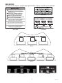
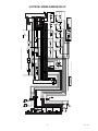
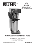
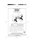
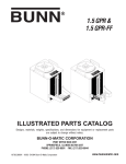
IMIX-3S
IMIX-5S
INSTALLATION & OPERATING MANUAL
BUNN-O-MATIC CORPORATION
POST OFFICE BOX 3227
SPRINGFIELD, ILLINOIS 62708-3227
PHONE: (217) 529-6601 FAX: (217) 529-6644
38526.0000B 04/06 ©2005 Bunn-O-Matic Corporation
www.bunnomatic.com
BUNN-O-MATIC COMMERCIAL PRODUCT WARRANTY
Bunn-O-Matic Corp. (“BUNN”) warrants equipment manufactured by it as follows:
1) All equipment other than as specified below: 2 years parts and 1 year labor.
2) Electronic circuit and/or control boards: parts and labor for 3 years.
3) Compressors on refrigeration equipment: 5 years parts and 1 year labor.
4) Grinding burrs on coffee grinding equipment to grind coffee to meet original factory screen sieve analysis:
parts and labor for 3 years or 30,000 pounds of coffee, whichever comes first.
These warranty periods run from the date of installation BUNN warrants that the equipment manufactured by
it will be commercially free of defects in material and workmanship existing at the time of manufacture and
appearing within the applicable warranty period. This warranty does not apply to any equipment, component or
part that was not manufactured by BUNN or that, in BUNN’s judgment, has been affected by misuse, neglect,
alteration, improper installation or operation, improper maintenance or repair, damage or casualty. This warranty is
conditioned on the Buyer 1) giving BUNN prompt notice of any claim to be made under this warranty by telephone
at (217) 529-6601 or by writing to Post Office Box 3227, Springfield, Illinois 62708-3227; 2) if requested by
BUNN, shipping the defective equipment prepaid to an authorized BUNN service location; and 3) receiving prior
authorization from BUNN that the defective equipment is under warranty.
THE FOREGOING WARRANTY IS EXCLUSIVE AND IS IN LIEU OF ANY OTHER WARRANTY, WRITTEN OR
ORAL, EXPRESS OR IMPLIED, INCLUDING, BUT NOT LIMITED TO, ANY IMPLIED WARRANTY OF EITHER
MERCHANTABILITY OR FITNESS FOR A PARTICULAR PURPOSE. The agents, dealers or employees of BUNN
are not authorized to make modifications to this warranty or to make additional warranties that are binding on
BUNN. Accordingly, statements by such individuals, whether oral or written, do not constitute warranties and
should not be relied upon.
If BUNN determines in its sole discretion that the equipment does not conform to the warranty, BUNN, at its
exclusive option while the equipment is under warranty, shall either 1) provide at no charge replacement parts
and/or labor (during the applicable parts and labor warranty periods specified above) to repair the defective
components, provided that this repair is done by a BUNN Authorized Service Representative; or 2) shall replace
the equipment or refund the purchase price for the equipment.
THE BUYER’S REMEDY AGAINST BUNN FOR THE BREACH OF ANY OBLIGATION ARISING OUT OF THE SALE OF
THIS EQUIPMENT, WHETHER DERIVED FROM WARRANTY OR OTHERWISE, SHALL BE LIMITED, AT BUNN’S
SOLE OPTION AS SPECIFIED HEREIN, TO REPAIR, REPLACEMENT OR REFUND.
In no event shall BUNN be liable for any other damage or loss, including, but not limited to, lost profits, lost sales,
loss of use of equipment, claims of Buyer’s customers, cost of capital, cost of down time, cost of substitute
equipment, facilities or services, or any other special, incidental or consequential damages.
INTRODUCTION
This equipment dispenses hot beverages or soups on demand from powdered product. It is indoor use only on
a sturdy counter or shelf.
36526 040706
USER NOTICES
The notices on this dispenser should be kept in good condition. Replace unreadable or damaged labels.
! WARNING
Fill water tank before turning - on thermostat or connecting appliance
to power source.
Use only on a properly protected
circuit capable of the rated load.
Electrically ground the chassis.
Follow national/local electrical codes.
Do not use near combustibles.
00656.0000
FAILURE TO COMPLY RISKS EQUIPMENT
DAMAGE, FIRE, OR SHOCK HAZARD
READ THE ENTIRE OPERATING MANUAL
BEFORE BUYING OR USING THIS PRODUCT
THIS APPLIANCE IS HEATED WHENEVER
CONNECTED TO A POWER SOURCE
00831.0000F 3/98 ©1998 BUNN-O-MATIC CORPORATION
00831.0000
28368.0000
IMIX-3S
IMIX-5S
! WARNING
HOT
LIQUID
RELEASE BUTTON WHEN CUP IS 3/4 FULL
PLACE
CUP
HERE
PLACE
CUP
HERE
PLACE
CUP
HERE
PLACE
CUP
HERE
PLACE
CUP
HERE
28328.0011
28328.0010
36526 040706
INITIAL SET-UP
1. Apply the four non-skid pads from the parts box to the bottom of the legs.
2. Remove the drip tray assembly, drip tray bracket, and splash panel assembly from the parts box.
3. Place a set of key holes in the drip tray bracket over the lower two screws in the panel below the hopper access door; push down gently and tighten screws.
4. Place the set of key holes in the splash panel over the upper two screws and position so the screws are
between the holes.
ELECTRICAL REQUIREMENTS
WARNING - If the power cord is ever damaged, it must be replaced by the manufacturer or its service agent with
a special cord available from the manufacturer or its service agent in order to avoid a hazard.
CAUTION - The dispenser must be disconnected from the power source until specified in Electrical Hook-Up.
The 120 volt version of this dispenser has an attached cordset.
Refer to the dispenser’s dataplate for exact voltage requirements.
Electrical Hook-Up
CAUTION – Improper electrical installation will damage electronic components.
1. An electrician must provide electrical service as specified.
2. Using a voltmeter, check the voltage and color coding of each conductor at the electrical source.
3. Open the front door of the dispenser and place the heater switch in the “OFF” (upper position).
4. Connect the dispenser to the power source.
5. If plumbing is to be hooked-up later be sure the dispenser is disconnected from the power source. If plumbing has been hooked-up, the dispenser is ready for Initial Fill & Heat.
PLUMBING REQUIREMENTS
This dispenser must be connected to a COLD WATER system with operating pressure between 20 and 100 psi
(138 and 690 kPa). This water source must be capable of producing a minimum flow rate of 4.5 fl. oz. (133.1
ml) per second. A shut-off valve should be installed in the line before the dispenser. Install a regulator in the
line when pressure is greater than 100 psi (690 kPa) to reduce it to 50 psi (345 kPa). The water inlet fitting is
.38" (9.52 mm) flare.
NOTE - At least 18 inches (457 mm) of an FDA approved flexible beverage tubing, such as reinforced braided
polyethylene or silicone, before the dispenser will facilitate movement to clean the countertop. It can be purchased
direct from Bunn-O-Matic (part number 32759.10--[See Illustrated Parts Catalog for complete part number]).
Bunn-O-Matic does not recommend the use of a saddle valve to install the dispenser. The size and shape of the
hole made in the supply line by this type of device may restrict water flow.
This equipment must be installed to comply with the Basic Plumbing Code of the Building
Officials and Code Administrators International, Inc. (BOCA) and the Food Service Sanitation Manual of the Food and Drug Administration (FDA). For models installed outside the
U.S.A., you must comply with the applicable Plumbing/Sanitation Code for your area.
PLUMBING HOOK-UP
1. Flush the water line and securely attach it to the flare fitting on the bottom of the dispenser.
2. Turn-on the water supply.
36526 102705
INITIAL fill & heat
CAUTION - The dispenser must be disconnected from the power source throughout the initial set-up, except
when specified in the instructions.
1. Turn-on the water supply and connect the dispenser to the power source.
2. Water will automatically flow into the tank to the proper level and then shut-off. This will take less than five
minutes.
3. When the tank is full of water, open the front door and place the heater switch in the “ON” (lower) position.
A tank full of cold water will take approximately eighty minutes (IMIX-5S) or forty-five minutes (IMIX-3S)
for the water to heat on 120 volt versions or forty minutes (IMIX-5S) or twenty-five minutes (IMIX-3S) for
120/208 volt versions and 120/240 volt versions.
During this waiting period, complete these dispenser set-up steps:
a. Place the drip tray in front of the dispenser. Set the drip tray cover in place.
b. Place a set of keyholes in the cup locator plate over the screws beneath the hopper access door and push
down gently.
c. Fill the hoppers with the dry product to be dispensed.
LIQUID LEVEL CONTROL
The system automatically maintains the hot water tank’s level by energizing the refill solenoid when the water
level drops below the liquid level probe. If the system has not successfully refilled in 15 minutes, a refill error
occurs. When a refill error occurs, the refill solenoid is de-energized and the left rinse L.E.D. will flash about
once every 5 seconds. Once the cause of the refill error has been investigated (see the troubleshooting guide in
the Operating and Service Manual) and cured, the system can be reset by placing the Rinse/Run switch in the
programming (center) position, momentarily.
RINSE TIMERS
The dispenser is shipped from the factory with the rinse timers disabled. To enable the rinse timers, remove
power from the dispenser, remove the lower access panel, and remove the jumper from J1 of the control boards.
Replace the lower access panel, and return power to the dispenser. When enabled, the rinse timers automatically keep track of the time since the dispenser was last run through a rinse sequence. If the dispenser detects
that a rinse sequence has not been run for 8 hours, the appropriate rinse L.E.D. will flash continually. If, after
an additional 4 hours (12 hours total), a rinse sequence has still not been run, the appropriate rinse L.E.D. will
light continuously, and the appropriate hopper drives will be disabled until a rinse sequence has been run.
RUNNING A RINSE SEQUENCE
1. Place the rinse/run switch in the rinse position.
2. Sequentially, or simultaneously, at each of the positions dispense for at least 10 seconds.
3. After the rinse L.E.D. has extinguished, the rinse timer is reset.
4. Return the rinse/run switch to the run position.
DISPENSER USE
1. Simply place a cup on the drip tray beneath the dispensing tip.
2. Press the button and dispense the beverage.
3. Release the button when the cup is approximately 3/4 full and allow the whipper chamber to drain.
NOTE - The whipper chamber must drain at the end of each dispense.
36526 040706
CLEANING
Refer to the decal on the rear of the dispenser door for cleaning recommendations and procedures.
The use of a damp cloth rinsed in any mild, non-abrasive, liquid detergent is recommended for cleaning all surfaces on Bunn-O-Matic equipment. Do NOT clean this equipment with a water jet device.
ADJUSTMENTS
The beverage solenoid is preset to dispense approximately 9/10 ounce per second (26 mL/sec). This amount
can be adjusted:
1. Disconnect the dispenser from the power source.
2. Remove the hoppers and the access panel behind the hoppers.
3. Rotate the control at the base of the solenoid clockwise to decrease or counterclockwise to increase the
amount of water.
4. Replace access panel when finished.
HOPPER MOTOR SPEED PROGRAMING
NOTE: The hopper dispense rates are preset at the factory. With 22 tooth gear and auger wire the preset dispense rate is approximately 3 to 5 grams per second. With 30 tooth gear and auger wire the preset dispense is
approximately 5 to 7 grams per second. The hopper dispense rates can be individually programmed to a range
of dispense rates from approximately 1.5 to 12 grams per second, as follows:
1. Place the rinse/run switch in the center (program) position.
2. Hold the increase/decrease switch in the desired (increase or decrease) position.
3. While holding the increase/decrease switch, press and release the dispense switch for the chamber you wish
to adjust. Each time the dispense switch is pressed, the rinse L.E.D. will flash, and the motor speed for that
hopper will be increased/decreased by approximately 2 1/2%.
4. Return the rinse/run switch to the run position after hopper motor speed adjustments are complete.
For IMIX-3S only:
5. Once any of the three hopper motors has been programmed to the desired speed, either or both of the other
hopper motors can be set to the same speed as follows:
a. Place the rinse/run switch in the center (program) position.
b. Press and hold the dispense switch that has been programmed for the correct speed.
NOTE: Care must be taken not to exceed 5 seconds, or a hopper throw test will occur.
c. Momentarily press the dispense switch for the hopper motor to be programmed. The rinse L.E.D. will light
for approximately 1 second, indicating that the speeds have been set equal.
d. Release both dispense switches.
e. Repeat step 5. b. through 5. d. for remaining hopper motor if desired.
f. Return the rinse/run switch to the run position after hopper motor speed adjustments are complete.
DRAINING THE HOT WATER TANK
CAUTION - The dispenser must be disconnected from the power source throughout these steps.
1. Disconnect the dispenser from the power source.
2. Place the tank heater switch in the “OFF” position.
3. Shut-off and disconnect the incoming water supply.
4. Remove the front, lower access panel.
5. Pull out drain tube to empty into a sink or a container with a minimum of 7-1/2 gallon (28.5 L) capacity.
6. Make sure drain clamp is closed. Then, remove drain plug.
7. Direct tube into sink or container and open drain clamp. Continue draining tank until ALL of the water is
out.
WARNING: Be very careful with the draining water because it can be very hot.
8. Close drain clamp, insert drain plug, place drain tube back into machine, and replace lower access panel.
NOTE - The dispenser must be refilled using the INITIAL FILL & HEAT steps before reconnecting to the power
source.
36526 042806
ELECTRICAL WIRING DIAGRAM IMIX-3S
LEFT
LAMP
RIGHT
LAMP
36526 040706
GRY
1
"RINSE" #4 & 5 L.E.D.
RED/GRN
ORN/RED
BLU
BLU/BLK
LEFT LAMP
ASSY.
4
GRN
1
GRN
WHI
BLK/RED
BLU/RED
PNK
WHI
WHI
WHI/RED
WHI/GRN
BLK/RED
WHI
BLU/RED
1
38524.0000A 10/05
120 VOLTS AC - 2 WIRE
SINGLE PHASE, 60HZ
PROBE
GRN
RUN
PGM
RINSE
RUN
PGM
©2005 BUNN-O-MATIC CORPORATION
BRN/BLK
GRY
BRN/BLK
RINSE/PROGRAM/
RUN SWITCH
WHI/GRY RINSE
D
E
C
I
N
C
INCREASE/
DECREASE
SWITCH
OVERFLOW PROTECTION SWITCH
RED
RED
WHI/VIO
J1-4
WHI/VIO
GRY
WHI/GRY
WHI/RED
TAN
RED/BLK
WHI/BLK
WHI/ORN
GRN
PNK
WHI/ORN
WHI/RED
BRN/WHI
GRN
WHI/GRN
WHI/BLK
BLK
J1-1
J2-5
J2-1
J3-5
J3-1
J4-4
WHI
VIO
WHI
WHI/VIO
J2-10
C
O
N
T
R
O
L
C
I
R
C
U
I
T
B
O
A
R
D
#
1
J4-1
BLK-16
LAMP #1 BLK
BALLAST
WHI/VIO
GRN
RED
WHI
RED
BRN
RED
ORN
YEL
BLU
BRN/BLK
WHI/BLK
WHI/RED
WHI/ORN
WHI/YEL
WHI/BLU
GRN
BLK
K
RED/BLK
WHI/BLK
RED/BLK
ORN/BLK
GRN/BLK
BLU/BLK
BLK
BLK/WHI
RED
ORN
GRN/WHI
BLU
WHI/RED
BLK
BLK
GRN
BLK-16
BLK-16
BLK
GRN
RED
CONTROL
THERMOSTAT
LIMIT
THERMOSTAT
BLK-16
BLK
TAN
BLK
M
HOPPER #1
SOL
STATION #1
DISPENSE
VALVE
M
STATION #1
WHIPPER
RED
WHI
BLK
BLK
BLK
BLK
M
BRN
BRN
TAN
WHI
SOL
STATION #2
DISPENSE
VALVE
M
STATION #2
WHIPPER
RED
HOPPER #2
M
FAN
4
1
ORN
BLK
SOL
RED
RED
TAN
WHI
HOT
HOT/COLD SWITCH
COLD
WHI
BLK
BLK
WHI
WHI
WHI
WHI
N
SOL
WHI/YEL
STATION #3
DISPENSE
VALVE
M
STATION #3
WHIPPER
M
HOPPER #3
COLD DRINK OPTION (LEFT ONLY)
WHI
BLK
WHI/ORN
SOL
RED
WHI-16
REFILL VALVE
VIO
BLK
TANK HEATER
BLK
RED
WHI/RED
BLK
LOAD 120V : 24V AC LINE
TRANSFORMER
WHI
WHI/GRN
WHI/BLK
BLK LAMP #2 BLK
BALLAST
BRN/WHI
RED
BLK-16
GRN
TANK HEATER
SWITCH
BRN
GRN
GRN
SCHEMATIC WIRING DIAGRAM IMIX-5S
GRN
WHI
WHI/RED
BLK
RED
GRN/BLK
WHI
GRN/WHI
RED
4
WHI
WHI/RED
BLK
WHI
ORN
ORN/BLK
ORN
3
WHI
WHI/RED
BLK
ORN
RED
RED/BLK
WHI/YEL
YEL
2
4
WHI
WHI/RED
BLK
1
YEL
BLK/WHI
WHI/BLK
6
WHI
GRY
1
"RINSE" #1-3 L.E.D.
1
YEL
BLK
M
RED
RED
RED
SOL
STATION #4
DISPENSE
VALVE
M
STATION #4
WHIPPER
RED
HOPPER #4
K
BLU
J1-4
J1-1
J2-10
J2-5
J2-1
J3-5
J3-1
J4-4
J4-1
SOL
STATION #5
DISPENSE
VALVE
M
STATION #5
WHIPPER
M
HOPPER #5
RED
BLK
WHI/BLU
WHI/RED
WHI/BLK
WHI/VIO
GRY
WHI/GRY
WHI/BLU
BLU/BLK
RED/BLK
WHI/YEL
WHI/ORN
WHI/BLU
WHI/YEL
GRN
WHI/GRN
WHI/BLK
WHI
BRN/BLK
WHI
BLK
JUMPER PLUG MUST BE
USED WHEN COLD
DRINK FEATURE NOT
INSTALLED
WHI
BLK
BLK
GRN
BLU
RED/WHI
BLU/WHI
WHI
1
6
BLU
WHI/RED
BLK
1
1
WHI
PNK
WHI
GRN
BLK
BLK
C
O
N
T
R
O
L
C
I
R
C
U
I
T
B
O
A
R
D
#
2
WHI
WHI
TAN
GRN
BLU/BLK
GRN
L1
ELECTRICAL WIRING DIAGRAM IMIX-5S
4
5
RIGHT
LAMP ASSY.
36526 102705