1
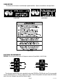
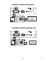
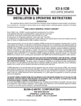
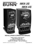
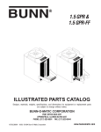
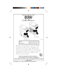
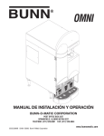
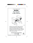
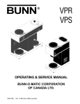
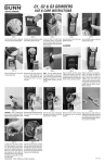
BUNN
®
IC3 & IC3B
ICED COFFEE BREWERS
INSTALLATION & OPERATING INSTRUCTIONS
INTRODUCTION
This equipment will brew a batch of fresh coffee into an awaiting vessel and dispense at approximately
room temperature to conserve ice. The brewer is only for indoor use on a sturdy counter or shelf and requires a
minimum of 33 inches of clearance above the counter.
WARRANTY
Bunn-O-Matic Corp. (“Bunn”) warrants the equipment manufactured by it to be commercially free from defects
in material and workmanship existing at the time of manufacture and appearing within one year from the date of
installation. In addition:
1.) Bunn warrants electronic circuit and/or control boards to be commercially free from defects in material and
workmanship for three years from the date of installation.
2.) Bunn warrants the compressor on refrigeration equipment to be commercially free from defects in material
and workmanship for two years from the date of installation.
3.) Bunn warrants that the grinding burrs on coffee grinding equipment will grind coffee to meet original factory
screen sieve analysis for three years from date of installation or for 30,000 pounds of coffee, whichever comes first.
This warranty does not apply to any equipment, component or part that was not manufactured by Bunn or that,
in Bunn’s judgement, has been affected by misuse, neglect, alteration, improper installation or operation, improper
maintenance or repair, damage or casualty.
THE FOREGOING WARRANTY IS EXCLUSIVE AND IS IN LIEU OF ANY OTHER WARRANTY, WRITTEN OR
ORAL, EXPRESS OR IMPLIED, INCLUDING, BUT NOT LIMITED TO, ANY IMPLIED WARRANTY OF EITHER
MERCHANTABILITY OR FITNESS FOR A PARTICULAR PURPOSE. The agents, dealers or employees of Bunn are
not authorized to make modifications to this warranty or to make additional warranties that are binding on Bunn.
Accordingly, statements by such individuals, whether oral or written, do not constitute warranties and should not
be relied upon.
The Buyer shall give Bunn prompt notice of any claim to be made under this warranty by telephone at (217)
529-6601 or by writing to Post Office Box 3227, Springfield, Illinois, 62708-3227. If requested by Bunn, the Buyer
shall ship the defective equipment prepaid to an authorized Bunn service location. If Bunn determines, in its sole
discretion, that the equipment does not conform to the warranty, Bunn shall repair the equipment with no charge
for parts during the warranty period and no charge for labor by a Bunn Authorized Service Representative during
the warranty period. If Bunn determines that repair is not feasible, Bunn shall, at its sole option, replace the
equipment or refund the purchase price for the equipment.
THE BUYER’S REMEDY AGAINST BUNN FOR THE BREACH OF ANY OBLIGATION ARISING OUT OF THE SALE
OF THIS EQUIPMENT, WHETHER DERIVED FROM WARRANTY OR OTHERWISE, SHALL BE LIMITED, AS
SPECIFIED HEREIN, TO REPAIR OR, AT BUNN’S SOLE OPTION, REPLACEMENT OR REFUND.
In no event shall Bunn be liable for any other damage or loss, including, but not limited to, lost profits, lost sales,
loss of use of equipment, claims of Buyer’s customers, cost of capital, cost of down time, cost of substitute
equipment, facilities or services, or any other special, incidental or consequential damages.
BUNN-O-MATIC CORPORATION
POST OFFICE BOX 3227
SPRINGFIELD, ILLINOIS 62708-3227
PHONE: (217) 529-6601 FAX: (217) 529-6644
10792.0000B
9/01 © 1994 BUNN-O-MATIC CORPORATION
www.bunnomatic.com
USER NOTICES
The notices on this brewer should be kept in good condition. Replace unreadable or damaged labels.
03408.0000
03409.0000
00831.0000
ELECTRICAL REQUIREMENTS
CAUTION - Do not connect the brewer to the power source until specified in Initial Set-Up.
L2 RED
L2 RED
WHITE
120V.A.C.
208 or 240V.A.C.
NEUTRAL
L1 BLACK
200V.A.C.
120V.A.C.
L1 BLACK
These brewers require either 3-wire, grounded service rated 120/208 or 120/240 volts ac or 2-wire, grounded
service rated 200 volts ac, or 20 amp, single phase, 60 Hz. Refer to the product’s data plate above the dilution
nozzle for actual voltage of your particular brewer model.
Page 2
10792 021594
Electrical Hook-Up
CAUTION – Improper electrical installation will damage electronic components.
1. An electrician must provide electrical service as specified.
2. Remove the top lid and rotate the control thermostat knob fully counterclockwise to the “OFF” position and
reinstall the top lid.
3. Remove the rear trunk panel, feed the cord through the strain relief at the rear of the brewer and connect it to
the terminal block.
4. Using a voltmeter, check the voltage and color coding of each conductor at the power source.
5. Connect the brewer to the power source and verify the voltage at the terminal block and reinstall the rear
trunk panel.
6. If plumbing is to be hooked up later be sure the brewer is disconnected from the power source. If plumbing
has been hooked up, the brewer is ready for Initial Set-Up.
WARNING – The brewer must be electrically grounded using the green screw near the terminal block. Do not
assume a plumbing line will provide an adequate ground.
PLUMBING REQUIREMENTS
This brewer must be connected to a cold water system with operating pressure between 30 (207 kPa) and 90
psi (620 kPa) from a 1⁄2" or larger supply line. A shut-off valve should be installed in the line before the brewer.
Install a regulator in the line when pressure is greater than 90 psi(620 kPa) to reduce it to 50 psi (345 kPa). The
water inlet fitting is 1⁄4" flare.
NOTE - Bunn-O-Matic recommends 1⁄4" copper tubing for installations of less than 25 feet and 3⁄8" for more than
25 feet from the 1⁄2" water supply line. A tight coil of copper tubing in the water line will facilitate moving the
brewer to clean the countertop. Bunn-O-Matic does not recommend the use of a saddle valve to install the
brewer. The size and shape of the hole made in the supply line by this type of device may restrict water flow.
This equipment must be installed to comply with the Basic Plumbing Code
of the Building Officials and Code Administrators International, Inc. (BOCA)
and the Food Service Sanitation Manual of the Food and Drug Administration (FDA).
Plumbing Hook-Up
1. Attach the female fitting from the short piece of tubing on the strainer assembly (supplied) to the water inlet
fitting on the rear of the brewer.
2. Flush the water line and securely attach it to the flare fitting on the strainer assembly.
3. Turn on the water supply.
INITIAL SET-UP
CAUTION - The brewer must be disconnected from the power source throughout the initial set-up, except when
specified in the instructions.
1.
2.
3.
4.
5.
Remove the top lid from the brewer.
Rotate the control thermostat knob fully counterclockwise to the "OFF" position and replace the top lid.
Insert an empty funnel into the funnel rails.
Place an empty dispenser on the brewer base. Be prepared to empty the dispenser during these initial steps.
Plug in the brewer, place the ON/OFF switch in the "ON" position, and momentarily press the START switch.
Page 3
10792 021594
INITIAL SET-UP (cont.)
Water will flow into the tank and dispenser for five minutes and forty-five seconds. Empty the dispenser
when this first cycle stops and press the START switch again. Empty the dispenser when the second cycle
stops and press the START switch once more. During the third cycle, the tank will fill to its capacity and the
excess will flow from the funnel into the dispenser. Empty the dispenser when this third cycle stops.
6. Disconnect the brewer from the power source, remove the rear trunk panel, and turn the handle on the needle
valve approximately one-quarter turn counterclockwise to enable the flow of dilution water. This valve is fully
closed at the factory.
NOTE - The next step requires the use of a stopwatch to calculate the amount of dilution water flowing from the
nozzle in one minute. You’ll need to capture and measure the timed dilution water in a separate vessel than
the one used for the water flowing from the funnel.
7. Place a vessel under the brew funnel to catch the brew water. Use a hose or other means to divert the water
from the dilution nozzle to a separate container.
8. Connect the brewer to the power source. Simultaneously press the start switch to begin another brew cycle
and start the stop watch. Place the ON/OFF switch in the “OFF” position at exactly sixty-seconds (oneminute). When the flow of water stops, measure the volume of the captured dilution water. It should be
approximately twenty-two ounces.
9. If not, disconnect the brewer from the power source, and adjust the handle on the needle valve clockwise to
decrease the amount of water or counterclockwise to increase the amount of dilution water as required.
10. Repeat steps 8 & 9 until the recommended dilution water volume (twenty-two ounces) is achieved.
11. Disconnect the brewer from the power source and reinstall the rear trunk panel.
12. Unplug the brewer, remove the top lid, rotate the control thermostat knob fully clockwise to the "ON" position
and replace the top lid.
13. Empty the dispenser.
14. Connect the brewer to the power source and wait for the ready light to glow indicating the water in the tank
has heated to brewing temperature (approximately 20 minutes). Some water will drip from the funnel during
this time; this is due to expansion and should not occur thereafter.
15. Begin another brew cycle and measure the total water volume from the dispenser. It should be approximately
3 gallons and 12 ounces. (396 ounces).
16. If not adjust the timer as required. See Adjusting Brew Volumes.
17. Start, and measure another cycle.
18. Repeat steps 16-17 until the recommended total water volume is achieved.
19. The brewer is now ready to brew a batch of freshly brewed room temperature coffee.
ADJUSTING BREW VOLUMES
CAUTION - Disconnect the power source from the brewer prior to the removal of any panel for the replacement
or adjustment of any component.
NOTE: Prior to setting or modifying batch sizes, check that the brewer is connected to water supply, the tank is
properly filled, and a funnel and server are in place.
1. Modifying batch sizes. To modify a batch volume, first check that the SET/LOCK switch is in the “SET”
position on the circuit board.
To increase a batch size. Press and hold the START or BREW switch until three clicks are heard. Release the
switch (Failure to release the switch within two seconds after the third click causes the volume setting to be
aborted and previous volume setting will remain in memory) and press it again one or more times. Each time
the switch is pressed, two seconds are added to the brew time period. Allow the brew cycle to finish in order
to verify that the desired volume has been achieved.
To decrease a batch size. Press and release the START or BREW switch once for every two-second interval
Page 4
10792 091701
ADJUSTING BREW VOLUMES (cont.)
to be removed from the total brew time period; then immediately press and hold down the START or BREW
switch until three clicks are heard. Release the switch. (Failure to release the switch within two seconds after
the third click causes the volume setting to be aborted and previous volume setting will remain in memory).
Allow the brew cycle to finish in order to verify that the desired volume has been achieved.
2. Setting batch sizes. To set a batch volume, first check that the SET/LOCK switch is in the “SET” position on
the circuit board. Press and hold the START or BREW switch until three distinct clicks are heard (approximately 10 seconds) and then release the switch. (Failure to release the switch within two seconds after the
third click causes the volume setting to be aborted and previous volume setting will remain in memory). View
the level of the liquid being dispensed. When the desired level is reached, turn the ON/OFF switch to “OFF”
(lower). The brewer remembers this volume and will continue to brew batches of this size until the volume
setting procedure is repeated.
NOTE: When brewing tea, batch volumes will decrease due to absorption by the tea leaves.
3. Setting programming disable feature. If it becomes necessary to prevent anyone from changing brew times
once programmed, you can set the SET/LOCK switch to the “LOCK” position. This will prevent any programming to be done until switch is once again placed in the “SET” position.
CLEANING
CAUTION - Clean and sanitize your iced coffee brewer daily
1. Remove and thoroughly clean the entire brew funnel. The funnel must be free from any coffee particles or
residue.
2. Disconnect the brewer from the power source. Remove and thoroughly rinse the sprayhead. Wipe the
sprayhead panel clean with a damp cloth.
3. Insert the deliming spring into the sprayhead fitting until no more than one inch is visible and move it in and
out 5 or 6 times. Insert the spring into the airvent hole in the sprayhead panel and move it in and out 5 or 6
times. Reattach the sprayhead.
4. Wash the entire outside surface of the brewer with a clean damp cloth.
CAUTION - Do not keep brewed coffee overnight. The dispenser must be cleaned and sanitized daily.
OPERATING CONTROLS
A. Lighted On/Off Switch
ON - Placing the switch in the lighted upper position allows the start switch to activate a brew cycle.
OFF - Placing the switch in the lower position stops the brew cycle. Stopping a brew cycle after it has been
started will not stop the flow of water into the funnel until the tank syphons down to its proper level.
NOTE - The switch should always be placed in the “OFF” position after a brew cycle and whenever the brewer is
unattended.
B. Full/Half Batch Selector Switch
Full - Placing the switch in the upper position produces a full batch of room temperature coffee from the brew
cycle.
Half - Placing the switch in the lower position produces half of a full batch of room temperature coffee from the
brew cycle.
C. Start Switch
Starts a brew cycle when the lighted On/Off switch is in the “ON” position.
Page 5
10792 091701
COFFEE BREWING
1. Begin each brew cycle with a clean empty brew funnel and dispenser. (Be sure the dispenser lid doesn’t
interfere with the flow of dilution water.)
2. Insert a BUNN® 3-gallon urn filter into the funnel.
3. Pour the recommended amount of fresh coffee into the filter.
4. Level the bed of coffee grounds by gently shaking.
5. Slide the funnel into the funnel rails until it stops.
6. Place the On/Off switch in the lighted “ON” position.
7. Place the batch selector switch in the desired position.
8. Momentarily press the start switch.
CAUTION - The funnel contains hot liquids. Remove funnel slowly.
9. Carefully remove the funnel and discard the used filter when coffee no longer drips from the funnel.
10. Place the lighted On/Off switch in the “OFF” position to prevent a false start.
11. Room temperature fresh coffee is available at the faucet.
REPLACEMENT PARTS
03772.0001 .... Base Guide
05920.0000 .... Cable Clamp .25”
00603.0000 .... Cable Clamp .437”
03024.0005 .... Control Thermostat
03409.0000 .... Decal, Caution, Hot Liquid
03408.0000 .... Decal, Caution, Remove Funnel Slowly
24447.0000 .... Decal, Hood Front
03717.0000 .... Dilution Nozzle
03773.0000 .... Dilution Nozzle Spacer Housing
24613.0001 .... Fitting, .25” Flare x .128” MPT Adapter
22397.0001 .... Fitting, .25” Hose Barb x .125” MPT
00459.0000 .... Fitting, Bulkhead, .25” Male Flare
00400.0001 .... Fitting, Elbow, .25” Male Flare x .125” MPT
00412.0001 .... Fitting, Hex Nipple, .125” MPT
00432.0001 .... Fitting, Street Elbow, .125” NPT
24599.0001 .... Fitting, Tee Union, .125” FPT
24614.0001 .... Fitting, Union, .25” Female Flare
20528.1330 .... Flow Control Assy, .33 gpm
01155.0000 .... Flow Control Gasket
01154.0001 .... Flow Control Outlet
20526.1330 .... Flow Control Washer, .33 gpm
24600.0000 .... Foot Replacement Kit
12485.0003 .... Funnel Handle
24659.0000 .... Funnel Handle Mounting Bracket
12499.0000 .... Funnel Handle Screw
24657.0000 .... Funnel, Assy, Complete
12305.1000 .... Heater Kit, 4000W/208V or 3700W/200V
12322.1000 .... Heater Kit, 4000W/240V
00668.0000 .... Hole Plug, .75” Dia
12422.0000 .... Hose Clamp .5”
23717.0001 .... Limit Thermostat
03170.0000 .... Mounting
00484.0002 .... Needle Valve
12984.0004 .... Ready Indicator Assy, Green
10966.0000 .... Shipping Carton Complete
01592.0000 .... Snap Bushing 1” Dia
01079.0000 .... Solenoid Valve Base
01101.0000 .... Solenoid Valve Coil, (IC3)
21181.0000 .... Solenoid Valve Coil, (IC3B)
01111.0000 .... Solenoid Valve Repair Kit
01085.0002 .... Solenoid Valve, (IC3)
21180.0000 .... Solenoid Valve, (IC3B)
24527.0000 .... Sprayhead Assy
05515.0000 .... Sprayhead Tube Gasket
24697.0000 .... Sprayhead Tube Kit
02753.0000 .... Switch, Lighted On/Off, (IC3)
02754.0000 .... Switch, Lighted On/Off, (IC3B)
02628.0000 .... Switch, Momentary Start
05789.0000 .... Switch, Rocker, Batch Selector
24612.0000 .... Tank
24410.0000 .... Tank Lid
12377.0000 .... Tank Lid Gasket
07038.0000 .... Terminal Block, (IC3)
01106.0001 .... Terminal Block, (IC3B)
32400.0002 .... Timer kit, Digital (120V) (IC3)
32400.0001 .... Timer, kit, Digital (240V) (IC3B)
24435.0000 .... Top Lid
24427.0000 .... Trunk Extension Rear Panel
24698.0000 .... Trunk Rear Panel
00310.0005 .... Tube Assy, Bulkhead Fitting to Solenoid
24569.0000 .... Tube Assy, Flow Control To Tank
24531.0000 .... Tube Assy, Tank Fill
24532.0000 .... Tube Assy, Vent
00310.0000 .... Tube Assy, Water Strainer to Bulkhead Fitting
11707.1001 .... Tube, Silicone-.25” ID x 36"
22249.0000 .... Water Strainer End Cap .25” Flare
23721.0000 .... Water Strainer Replacement Screen
23820.1000 .... Water strainer Assy., Complete
02240.0002 .... Wire Assy, 1/2 Batch Switch to Timer
21014.0055 .... Wire Assy, Limit Thermostat to Tank Heater
24533.0000 .... Wiring Harness, Main (IC3)
24533.0001 .... Wiring Harness, Main (IC3B)
Page 6
10792 091701
SCHEMATIC WIRING DIAGRAM IC3
READY INDICATOR
L1
BLK
L2
GRN
BLU
N
LIMIT
THERMOSTAT
SW. & THERMOSTAT
BLK
BLK
BLU
TANK HEATER
RED
4000W
ON/OFF SW
BLK
WHI
WHI
WHI/RED
BREW
TIMER
1
2
3
4
5
WHI/RED
WHI/RED
WHI
WHI/ORA
WHI/GRN
WHI/YEL
PIN
GRY
START SW
SOL
FULL/HALF SW
120/208 VOLTS AC
OR 120/240 VOLTS AC
3 WIRE
SINGLE PHASE
10793.0000A 2/94
©1994 BUNN-O-MATIC CORPORATION
SCHEMATIC WIRING DIAGRAM IC3B
READY INDICATOR
L1
BLK
LIMIT
THERMOSTAT
SW. & THERMOSTAT
BLK
L2
GRN
BLU
BLK
BLU
TANK HEATER
RED
4000W
ON/OFF SW
BLK
BREW
TIMER
WHI/RED
1
2
3
4
5
RED
RED
WHI/RED
RED
WHI/ORA
WHI/GRN
WHI/YEL
PIN
GRY
WHI/RED
START SW
SOL
FULL/HALF SW
200 VOLTS AC
2 WIRE
SINGLE PHASE
10800.0000A 2/94
©1994 BUNN-O-MATIC CORPORATION
Page 7
10792 021594