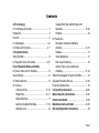
1
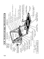
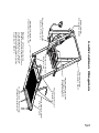
/PERATORgS-ANUALFOR
:$51,1*
,5!23
5LTRA
3ERIES
2SH
UD
0DQ WRU
XD V
O
#OMMERCIAL7HEELCHAIR,IFTS
0ROVIDING!CCESSTOTHE7ORLD
)NTERNATIONAL#ORPORATE(DQRS0/"OX7INAMAC).53!
4(%,)&4&!8
-ARCH
¤
¤
5HDGPDQXDO
EHIRUHRSHUDWLQJ
OLIW)DLOXUHWRGR
VRPD\UHVXOWLQ
VHULRXVERGLO\
LQMXU\DQGRU
SURSHUW\GDPDJH
.HHSPDQXDOLQ
OLIWVWRUDJHSRXFK
Congratulations
We at The Braun Corporation wish to express our fullest appreciation
on your new purchase. With you in mind, our skilled craftsmen have designed and assembled the finest lift available.
This manual includes safety precautions, lift operating instructions,
manual operating instructions, and instructions for maintenance and lubrication procedures.
Your lift is built for dependability, and will bring you years of pleasure
and independence, as long as maintenance is performed regularly and the lift
is operated by an instructed person.
Sincerely,
THE BRAUN CORPORATION
Ralph W. Braun
Chief Executive Officer
Contents
Lift Terminology
Lift Terminology Illustration ........................................ 2
Introduction ................................................................ 3
Direction ..................................................................... 3
Lift Components ...................................................... 4-6
Lift Actions and Functions ...................................... 6, 7
Lift Operation Safety
Safety Symbols .......................................................... 8
Lift Operation Safety Precautions ......................... 9-12
Pre-Lift Operation Notes and Details
Lift Access Doors and Lift Interlocks ........................ 13
General Safety ......................................................... 14
Lift Control Switches ................................................ 14
Lift Features
Unfold and Fold ........................................... 15, 16
Bridge Plate ................................................. 16, 17
Inboard Roll Stop .............................................. 17
Automatic Outboard Roll Stop ..................... 17, 18
Roll Stop Latch .................................................. 18
Outboard Roll Stop and Roll Stop Latch
Operation ..................................................... 19, 20
Handrails ........................................................... 20
Lift Passengers
Passenger Orientation (Boarding
Direction) ..................................................... 20, 21
Standees ........................................................... 21
Yellow Boundaries ............................................. 21
Floor Level Positioning ...................................... 22
Vehicle (Floor Level) Loading and
Unloading .................................................... 22, 23
Wheelchair-Equipped Occupant Seat Belts ............. 24
Operation Procedure Review ............................. 24, 25
Preventive Maintenance ........................................... 25
Lift Operating Instructions ............................... 26-30
Manual Operating Instructions ........................ 31-40
Decals and Antiskid .......................................... 41-43
Maintenance and Lubrication ......................... 44, 45
Warranty/Registration Instructions ...................... 46
Page 1
N
DOW
LD
UNFO )
(OUT
UP
FOLD
(IN)
Horseshoe
(a, b and c)
Right (Front)
Outboard
Inboard
Left (Rear)
As viewed from
outside the vehicle
Slide
Tubes
Roll Stop
Latch
Automatic Outboard
Roll Stop (ARS)
Side Plate
Yellow Boundary
(Edge Liner-2)
Platform
Adjustable
Handrail Stop
Dual Handrails
(standard on L211
Series lift models)
Inboard Roll Stop (L211
Series lift models only)
Bridge Plate Flap
Whale
Bridge Plate Ends (2)
Gussets (2)
Adjustable Quiet-Ride Bumper
Striker Back
Hand Pump Handle
c. Horseshoe Tube
“Bolt-on”
Upright (2)
Adjustable
Handrail Stop
Platform Side
Plate (2)
Platform Pickup
(fold) Bearings (2)
Whale (Powered)
Actuator Hairpin
Cotter (Bottom)
Base
Plate
b. Cylinder
Channel
a. Header
Cylinder (inside)
(not visible)
Actuator Hairpin
Cotter (Top)
Electric Fold
Actuator
Pump
Module
Hand-Held
Attendant's
Control Box
Actuator
QuickRelease
Pin
Handle
Detent Pin
Actuator
Manual
Release
Handle
Lift Terminology Illustration
TM
Page 2
Lift Terminology
Introduction
L200UARS Series lifts are
commercial oriented (intended for
operation by an attendant). The
L200UARS Lift Series includes
many standard lift models that
vary in height and width. A
standard L211UARS Series lift
model is depicted in the Lift
Terminology Illustration. Lift
model numbers indicate lift
dimensions. Model numbers of
special order (nonstandard) lifts
include other identification
information exclusive to specific
applications.
Lift operation procedures are the
same for all L200UARS Series lift
models. The operating instructions contained in this manual
and posted on the lift address the
lift control switches and the
corresponding lift functions only.
Instructions are provided for
manual operation of the lift in
event of power or equipment
failure.
L200UARS Series lifts are
installed in various types of
transit vehicles with varying lift
access door configurations. The
attendant must become familiar
with the proper operation of the
lift as well as the vehicle lift door
system and the lift interlock
system (if equipped). It is the
responsibility of the lift operator
(attendant) to properly open,
secure and close the vehicle lift
door(s), to activate the lift interlock (if equipped), to load and
unload the wheelchair passenger
(or standee) on and off the
platform, and to properly activate
all lift functions.
Terminology: Become familiar
with the terminology that will be
used throughout this manual.
Become familiar with the identification of lift components and
their functions. Contact your lift
sales representative or call The
Braun Corporation at 1-800-THE
LIFT if any of this information is
not fully understood.
Direction: The terms "left
(rear)," "right (front)," "inboard,"
and "outboard" will be used
throughout this manual to indicate direction (as viewed from
outside the vehicle looking
directly at the lift). Refer to the
Lift Terminology Illustrations for
clarification of direction terms.
Page 3
Lift Terminology
Lift Components
Refer to the Lift Terminology
Illustration on page 2.
Lift Frame (Base Plate and
Upright Assembly): The main
lift frame consists of the base
plate weldment (with two gussets), two bolt-on uprights, the
striker back assembly, the bridge
plate flap and two folding whales.
The base plate and upright
assembly supports the horseshoe
and platform assembly. The rod
end (bottom) of the electric fold
actuator is mounted to the left
side (rear) whale.
Bridge Plate: The bridge plate
assembly consists of the striker
back and the bridge plate flap.
The independent hinged bridge
Page 4
plate flap bridges the gap between the lift platform and the
vehicle floor when the platform is
positioned at floor level.
(rear) whale to power the fold and
unfold functions. The right side
(front) whale and bearing keep
the lift in alignment (unison).
The bridge plate travels from the
stowed position to the bridging
(horizontal) position as the lift
platform unfolds and vice versa.
Photos and further details regarding operation of the bridge plate
are provided in the Pre-Lift
Operation Notes section (page 16).
Horseshoe: The lift horseshoe is
the U-shaped metal frame
consisting of the header (top
crossmember), the cylinder
channel on the left and the
horseshoe tube on the right. The
horseshoe contains and protects
the platform slide tube assembly,
the hydraulic cylinder and the
lifting chain assemblies. The
pump module is mounted to the
inboard face of the cylinder
channel. The motor end (top) of
the electric fold actuator is
mounted to the outboard face of
the cylinder channel. The horseshoe pivots on two shoulder bolts
as the lift unfolds and folds.
Whales: L200UARS Series lifts
are equipped with two folding
whales. The jaws of the whales
engage the platform pickup
bearings to fold and unfold the
platform (one bearing located on
each side of the platform). The
rod end (bottom) of the electric
fold actuator is mounted to the left
Lift Terminology
Pump Module: The lift-mounted
pump module consists of the
hydraulic pump, the manual hand
pump and electrical components
that power the lift electric/hydraulic systems.
Hand-held Control Switchbox:
The hand-held control switchbox
is connected to the pump module. The control box is equipped
with two color-coded rocker
switches labeled UNFOLD (Out),
FOLD (In), UP and DOWN. The
switches activate the powered lift
functions. Details regarding the
control switches and their functions are provided in the Pre-Lift
Operation Notes section (page
14).
Fold Actuator: The electric
motor-driven actuator unfolds
and folds the platform when the
UNFOLD (Out)/FOLD (In) switch
is activated. The platform must
be in the fully-raised position
before the platform can be
unfolded or folded. Further
details in the Pre-Lift operation
section (pages 15 and 16).
down from ground level to the
vehicle floor. The lift platform
assembly consists of the frame
with grating surface upon which
the wheelchair is positioned, the
inboard roll stop (L211UARS lift
models), the outboard roll stop
and the handrails (if equipped).
Slide Tube Assembly: The slide
tube assembly carries the
platform assembly as it lowers
and raises. The slide tube
assembly consists of two telescoping slide tubes connected to
chain assemblies that travel up
and down inside the horseshoe,
the bottom support crossbar and
two platform mounting plates.
Dual Handrails: Dual handrails
are provided for wheelchair
passenger (or standee) use
(standard on L211 Series lift
models). The handrails are
mounted on the platform and
pivot as the lift unfolds and folds.
Platform Assembly: The lift
platform carries the wheelchair
passenger (or standee) up and
Outboard Roll Stop: The
outboard roll stop is the automatic chain-driven outer barrier
that provides a ramp for wheelchair loading and unloading at
ground level. Photos and further
Page 5
Lift Terminology
Lift Components (continued)
details regarding the outboard roll
stop are provided in the Pre-Lift
Operation Notes section (pages
17-20).
Roll Stop Latch: The springloaded latch locks the outboard
roll stop in the vertical position
when the platform raises above
ground level.
Inboard Roll Stop: L211UARS
platforms are equipped with a
fixed inboard roll stop. Attendant
operation is not required for
operation.
Manual Operation Systems:
Manual operation systems are
provided for use in event of
power or equipment failure.
Page 6
L200UARS Series lifts are
equipped with an “over-center”
fold actuator manual release
system to allow the lift platform to
be manually unfolded and folded.
A manual back-up hand pump is
built into the pump module. The
lift platform can be lowered and
raised using the hand pump.
Complete details and manual
operating procedures are provided on pages 31-40.
Lift Actions and Functions
UNFOLD (Out) - Platform
Unfold: Unfold is the action of
the platform rotating out and
down from the fully-stowed
(vertical) position to the fullyunfolded (horizontal) position
when the UNFOLD (Out) switch
is pressed.
DOWN - Platform Lower: Down
is the action of the platform
lowering when the DOWN switch
is pressed. When the platform is
unfolded from the stow position,
the platform must be lowered
from the fully-raised position to
the floor level position when
unloading a passenger at floor
level. The lift operator (attendant) must stop the platform at
floor level (release DOWN
switch). The platform is then
lowered to ground level (fullylowered) to unload and/or load
passengers.
DOWN - Roll Stop Unfold
(Deploy): When the platform
reaches the fully-lowered (ground
level) position and the DOWN
switch is continually pressed, the
outboard roll stop rotates down
Lift Terminology
ward from the vertical position to
the ramp position.
before the lift can be folded
(stowed).
UP - Roll Stop Fold (Raise):
When the platform is fully-lowered
and the roll stop is in the ramp
position, pressing the UP switch
first rotates the roll stop upward
from the ramp position to the
vertical position.
Stow Position: The lift is stowed
when the platform has been fully
raised and platform has been
folded fully (vertical position).
UP - Platform Raise: Up is the
action of the platform raising
when the UP switch is pressed.
The platform must be raised to
and stopped at floor level when a
wheelchair passenger (or
standee) is entering or exiting the
vehicle. The platform then must
be raised fully (above floor level)
Floor Level: Floor level is the
position (height) the platform must
be positioned in order for the
wheelchair passenger (or standee)
to enter and exit the vehicle. The
platform must be positioned such
that there is a smooth and level
transition between the platform,
bridge plate and vehicle floor. The
platform must be positioned
(lowered or raised), and stopped
at floor level by the lift operator
(attendant).
Deploy: Lift deployment is the
action of the platform unfolding,
the platform lowering to ground
level and the outboard roll stop
unfolding to the ramp position.
Stow: Stow is the action of the
outboard roll stop folding (raising)
to the vertical position, the
platform raising to the fully-raised
position and the platform folding
to the stowed (vertical) position.
Note: Further details regarding
lift control switches and the
corresponding lift functions are
provided in the Pre-Lift Operating
Notes section.
Page 7
Lift Operation Safety
Safety Symbols
SAFETY FIRST!
Know That....
All information contained
in this manual and
supplements (if included), is
provided for your safety. Familiarity with proper operation
instructions as well as proper
maintenance procedures are
necessary to ensure safe,
troublefree operation. Safety
precautions are provided to
identify potentially hazardous
situations and provide instruction
on how to avoid them.
A
D
B
WARNING
This symbol indicates
important safety
information regarding
a potentially hazardous situation that
could result in serious
bodily injury and/or
property damage.
C
CAUTION
This symbol indicates
important information
regarding how to
avoid a hazardous
situation that could
result in minor personal injury or property damage.
Note: Additional information provided to help clarify or detail a specific subject.
These symbols will appear throughout this manual as well as on the labels posted on your lift. Recognize
the seriousness of this information.
Page 8
Lift Operation Safety
Lift Operation Safety Precautions
WARNING Read manual and supplement(s) before operating lift. Read and become familiar with all
safety precautions, pre-lift operation notes and details, operating instructions and manual
operating instructions before operating the lift.
WARNING Load and unload on level surface only.
WARNING Engage vehicle parking brake before operating lift.
WARNING Provide adequate clearance outside the vehicle to accommodate the lift before opening lift
door(s) or operating lift.
WARNING Load and unload clear of vehicular traffic.
WARNING Open lift door(s) fully and secure before operating lift.
WARNING Inspect lift before operation. Do not operate lift if you suspect lift damage, wear or any
abnormal condition.
WARNING
Keep operator and bystanders clear of area in which the lift operates.
WARNING
Lift attendants must ensure that lift occupants keep hands, arms and all other body parts
within the lift occupant area and clear of moving parts.
Page 9
Lift Operation Safety
Lift Operation Safety Precautions (continued)
WARNING Platform must be positioned at floor level (bridge plate height) when loading or unloading in
and out of vehicle.
WARNING The wheelchair-equipped torso restraint belt must be properly positioned and engaged
before loading onto the wheelchair lift platform.
WARNING Do not use the outboard roll stop as a barrier (brake). Stop and brake wheelchair when
loading onto the platform (manually stop and brake manual wheelchairs — stop powered
wheelchairs with the wheelchair controls).
WARNING Turn powered (electric) wheelchairs off when on lift platform.
WARNING Press the DOWN switch until the entire platform rests on ground level (lowered fully) and
the outboard roll stop is fully unfolded (ramp position) before loading or unloading a passenger at ground level.
WARNING Outboard platform roll stop must be fully unfolded (ramp position) until the entire wheelchair
(or standee) crosses roll stop when loading or unloading at ground level.
WARNING Do not overload or abuse. The load rating applies to both the raising and lowering functions - continuous lifting capacity is 800 lbs.
WARNING Do not operate or board your lift if you or your lift operator are intoxicated.
Page 10
Lift Operation Safety
WARNING
Whenever a wheelchair passenger (or standee) is on the platform, the:
• Passenger must be positioned fully inside yellow boundaries
• Wheelchair brakes must be locked
• Roll stop(s) must be UP
• Roll stop latch must be fully engaged
• Passenger must grip both handrails (if able)
WARNING
Passenger must lower head to clear door jamb header when loading or unloading at
vehicle floor level.
WARNING
Platform must be fully UP before pressing FOLD/UNFOLD (In/Out) switch.
WARNING
Accidental activation of control switch(es) may cause unintended operation(s).
WARNING
When performing manual unfold procedures, have an assistant support the platform
before pulling actuator quick-release pin.
WARNING
Maintenance and lubrication procedures must be performed as specified in this manual by
authorized (certified) service personnel.
Page 11
Lift Operation Safety
Lift Operation Safety Precautions (continued)
WARNING
Replace missing, worn or illegible decals.
WARNING
Keep this lift operator's manual in lift-mounted manual storage pouch when not in use.
WARNING
Never modify (alter) a Braun Corporation lift.
WARNING
Do not use accessory devices not authorized by The Braun Corporation.
WARNING
Do not remove any guards or covers.
WARNING
Keep clear of any hydraulic leak.
WARNING
Failure to follow these safety precautions may result in serious bodily injury and/or
property damage.
Page 12
Pre-Lift Operation Notes and Details
WARNING
Read and become
familiar with all lift
operation safety
precautions, pre-lift
operation notes and
details, operating
instructions and
manual operating
instructions prior to
operating the lift. If
this information is not
fully understood,
contact The Braun
Corporation immediately. Failure to do so
may result in serious
bodily injury and/or
property damage.
L200UARS Series lift models are
specifically designed to be
operated by an attendant. The
Lift Operating Instructions contained in this manual and posted
on the lift provide instructions for
operation of the lift only. Read
and become familiar with all lift
operation safety precautions, prelift operation notes and details,
operating instructions and manual
operating instructions before
attempting lift operation procedures.
Door securement devices
(latches, hooks, cables, etc.) and
procedures to operate them vary
as well.
Lift Access Doors and Lift
Interlocks: Attendants must
become familiar with the vehicle
lift access door system and the
interlock system (if equipped), as
well as the proper operation of
the lift. Transit vehicles and lift
access door configurations vary.
It is the responsibility of the lift
operator (attendant) to properly
open, secure and close the
vehicle lift door(s), to activate the
lift interlock (if equipped), to load
and unload the wheelchair
passenger (or standee) on and off
the lift platform, and to properly
Lift interlocks are required by
nearly all transit authorities.
Instructions for operation of
interlocks and door securement
systems cannot be addressed in
this manual or on lift-posted
operating instructions decals due
to the variety of procedures
required for operating them.
Page 13
Pre-Lift Operation Notes and Details
activate all lift functions.
General Safety: The lift operator
(attendant) and bystanders must
keep clear of the area in which
the lift operates and clear of all
moving parts. Lift attendants
must ensure that lift occupants
Lift Control Switches
The hand-held attendant’s control box provides
an orange UNFOLD/FOLD (Out/In) switch and
a red DOWN/UP switch. The control switches
are color-coded to correspond to the color
coding and switch function labels that appear
on the lift-posted operating instructions decal.
Triangular-shaped color-coded symbols (
)
appear on the lift operating instructions decal.
The color of the symbol corresponds to the
color of the corresponding switch. The direction (point) of the symbol corresponds with the
direction the switch should be activated
(pressed) to produce the intended lift function.
Page 14
(passengers) keep hands, arms
and all other body parts within the
lift occupant area and clear of
moving parts.
Orange UNFOLD/FOLD Switch
Press
switch
left for
UNFOLD
(Out)
Press
switch
right for
FOLD
(In)
Press
switch
left for
DOWN
(To Lower)
Press
switch
right for
UP
(To Raise)
Red DOWN/UP Switch
Pre-Lift Operation Notes and Details
Lift Features
Become familiar with all lift features and the proper operation of
the lift components before attempting lift operation. Refer to
the Lift Terminology Illustration on
page 2 for identification of specific
lift components if not clearly
depicted in this section. Contact
The Braun Corporation at 1-800THE LIFT immediately if any of
this information is not understood.
Unfold and Fold: Series 05 lift
models are equipped with
electric fold actuators that
feature a built-in overload clutch
that slips (ratchets) when it
reaches the end of its stroke
(during unfolding and folding
functions). The ratchet (audible
clicking) signals the lift operator
that the platform has reached
the fully unfolded position or the
fully folded position.
When pressing the orange
UNFOLD (Out) switch to unfold
the platform from the stowed
position, the lift operator must
continue to press the switch
until the actuator ratchets
(makes audible clicking). The
clicking sound indicates the
powered whale is fully unfolded
(deployed). If the actuator does
not ratchet, the whale has not
reached the fully unfolded
position and the lift may be
damaged when lowering or
raising the platform.
Note: The platform must be in
CAUTION
Press UNFOLD switch
until actuator makes
audible clicking
sound (ratchets).
Failure to do so may
result in lift damage.
the fully raised position before
the platform can be folded or
unfolded. If the platform does
not unfold when the UNFOLD
switch is pressed or the platform
does not fold when the FOLD
switch is pressed, press the UP
switch momentarily and try
again.
Page 15
Pre-Lift Operation Notes and Details
Lift Features (continued)
Before pressing the orange
FOLD (In) switch to fold the
platform to the stowed position,
the lift operator must press the
red UP switch to be certain the
platform is in the fully raised
position. The platform must be
in the fully raised position
before the platform can be
folded.
The lift operator should continue
to press the orange FOLD (In)
switch until the actuator ratchets
(makes audible clicking) when
folding the platform to the
stowed position to ensure the
lift is fully stowed.
Bridge Plate: The bridge plate
assembly consists of the striker
Page 16
back and the bridge plate flap.
The independent hinged bridge
plate flap bridges the gap
between the lift platform and the
vehicle floor when the platform
is positioned at floor level,
providing a surface for wheelchair (or standee) travel.
L200UARS Series lifts unfold
and fold at a position above
floor level (fully raised). The lift
attendant (operator) must
position (lower or raise), and
stop the platform at vehicle floor
level when a passenger is
entering or exiting the vehicle.
The platform must be properly
positioned at a height such that
The bridge plate unfolds (rotates) from the stowed position
Striker Back
to the bridging (horizontal)
position as the lift platform
unfolds and vice versa. The
bridge plate flap rests on the
platform when deployed
(unfolded). Read warning
posted on opposite page.
Discontinue lift operation
immediately if the bridge
plate does not operate
properly.
Bridge Plate Flap
Pre-Lift Operation Notes and Details
there is a smooth (level) transition between the platform, the
bridge plate assembly and the
vehicle floor. See Floor Level
Positioning on page 22.
Inboard Roll Stop: L211UARS
Series lift platforms are equipped
with a fixed 1" inboard roll stop
(shown below). Attendant
operation is not required for this
roll stop.
Automatic Outboard Roll
Stop: The automatic cylinderpowered chain-driven roll stop
provides a ramp for wheelchair
loading and unloading at ground
level. When the platform lowers
fully to ground level, the gas
spring automatically unfolds
(rotates) the roll stop to the
ramp position (fully unfolded).
Note: Outboard roll stop photos
on following page.
Although the outboard roll stop
is lift-powered, the activation of
the roll stop is controlled by the
lift operator (attendant). Press
WARNING
Inboard Roll Stop
L211UARS Series
Lift Models only
Discontinue lift use
immediately if any lift
component does not
operate properly.
Failure to do so may
result in serious
bodily injury and/or
property damage.
Page 17
Pre-Lift Operation Notes and Details
Lift Features (continued)
ing the DOWN switch deploys
(unfolds) the roll stop. The roll
stop is cylinder powered to
automatically fold (rotate) to the
vertical position when the UP
switch is pressed (roll stop
raises before platform raises).
Read warning posted on
opposite page. Discontinue
lift operation immediately if
the roll stop does not operate
properly.
Roll Stop Latch: A springloaded latch engages the
outboard roll stop when the roll
stop rotates upward from the
ramp position to the vertical
Fully Unfolded Roll Stop (Ramp position)
position (UP switch is pressed
to raise the platform above the
ground). Note: The platform
must raise approximately two
inches before the latch engages
fully (see photos below).
The latch disengages the roll
stop when the platform lowers
fully (reaches ground level) and
Fully Folded Roll Stop (Up-vertical)
Outboard Roll Stop
Disengaged
Roll Stop Latch
Fully Engaged
Roll Stop
Latch
Note: Platform must raise
approximately two inches
before latch engages fully.
Page 18
2"
Latch Foot
Pre-Lift Operation Notes and Details
the latch foot contacts the
ground (latch raises above the
roll stop).
Outboard Roll Stop and Roll
Stop Latch Operation: The
operator (attendant) must press
the DOWN switch to lower the
platform fully to the ground.
The attendant must view the
platform as it lowers to be
certain the entire platform
reaches and rests safely on the
ground (see photo below). Stop
pressing the DOWN switch if
any portion of the platform is
obstructed while descending or
the entire platform does not
reach ground level for any
reason (contact with an ob-
struction, mechanical failure,
exceeding the lift “floor-toground” capacity, etc.).
After the platform is fully lowered (entire platform reaches
ground level), the attendant
should continue to press the
WARNING
Discontinue lift use
immediately if any lift
component does not
operate properly.
Failure to do so may
result in serious
bodily injury and/or
property damage.
The attendant must view the
platform as it lowers to be
certain the entire platform
reaches and rests safely on
the ground.
Page 19
Pre-Lift Operation Notes and Details
Lift Features (continued)
DOWN switch to unfold the
outboard roll stop fully (ramp
position). Note: The roll stop
must be fully unfolded until the
entire wheelchair (or standee)
has crossed the roll stop when
loading or unloading at ground
level. Discontinue lift opera-
WARNING
Discontinue lift use
immediately if any lift
component does not
operate properly.
Failure to do so may
result in serious
bodily injury and/or
property damage.
Page 20
tion immediately if the roll stop
or latch do not operate properly.
Handrails: Dual handrails are
provided for wheelchair passenger (or standee) use (standard on
L211UARS lift models). Passengers should grip both handrails
when on the lift platform if able.
Discontinue lift operation if the
handrails do not operate
properly.
Lift Passengers
If you are an attendant operating
the lift, it is your responsibility to
perform safe loading and unloading procedures. Wheelchair lift
attendants should be instructed
on any special needs and/or
procedures required for safe
transport of wheelchair passengers.
The lift operator and bystanders
must keep clear of the area in
which the lift operates. Observe
your passenger at all times during
lift operation.
Do not attempt to load or unload a
passenger in a wheelchair or
other apparatus that does not fit
on the platform area. Do not
exceed the 800 pound load
capacity of the lift. The lift attendant should not ride on the
platform with the passenger.
Passenger Orientation (Boarding Direction): Braun L211UARS
Series ADA wheelchair lifts fully
comply with the ADA requirement
that the lift accommodate both
inboard and outboard facing
Pre-Lift Operation Notes and Details
wheelchair passengers or
standees. Inboard facing of
wheelchair lift passengers is not
prohibited, but outboard facing
of passengers is recommended
by The Braun Corporation (all lift
models).
Braun L211UARS Series ADA
certified lifts permit both inboard
and outboard facing of wheelchair
and mobility aid users and
accommodate persons using
walkers, crutches, canes or
braces or who otherwise have
difficulty using steps as specified
in Americans With Disabilities Act
(ADA) Accessibility Specifications
For Transportation Vehicles-Part
38.
Standees: Lift Operating Instructions apply to wheelchair passen-
gers and standees. Standees
should stand in the center of the
platform (fully inside the yellow
boundaries) and grip both handrails (if able) when on platform (if
so equipped).
Yellow Boundaries: The passenger must be positioned in the
center of the platform to prevent
side-to-side load imbalance. The
lift attendant (operator) should not
ride on the platform with the
passenger.
Yellow platform loading boundaries
are identified in the following
manner. Yellow antiskid is affixed
to the outboard roll stop and the
outboard edge of the bridge plate
flap (all lift models). Yellow plastic
edge liner (u-molding) is positioned
on both platform side plates (all lift
models). Yellow plastic edge
liner (u-molding) is positioned on
fixed inboard roll stops
(L211UARS lift models only).
Yellow antiskid is affixed to the
inboard end of platforms that are
not equipped with an inboard roll
stop. L211UARS handrails have
yellow grips.
The attendant must always be
certain the wheelchair passenger
or standee is properly positioned
on the platform (fully inside
yellow boundaries) and the
wheelchair brakes are locked
when a passenger is on the lift
platform. Lift attendants must
ensure that lift occupants (passengers) keep hands, arms and
all other body parts within the lift
occupant area and clear of all
moving parts.
Page 21
Pre-Lift Operation Notes and Details
Lift Passengers (continued)
Floor Level Positioning:
L200UARS series lifts unfold and
fold at a position above floor level
(fully-raised). See photo on left.
The lift attendant (operator) must
position (lower or raise), and
stop the platform at vehicle
floor level (bridge plate height)
when a passenger is entering or
exiting the vehicle. See photos
below. The platform must be
properly positioned at a height
such that there is a smooth (level)
transition between the platform,
the bridge plate assembly and the
vehicle floor.
It is the responsibility of the lift
operator (attendant) to ensure
the platform and the bridge
plate are properly positioned at
floor level when loading and
unloading passengers.
Vehicle (Floor Level) Loading
and Unloading: The platform
must be positioned at floor level
as previously detailed when
Floor Level Positioning
o
Flo
P
orm
latf
Hei
ght
r Le
vel
Fully Raised
Platform
Floor Level
Platform
ght
The lift attendant (operator) must
position platform at vehicle floor
level when a passenger is
entering or exiting the vehicle.
Page 22
or
Flo
Pla
m
tfor
Hei
el
Lev
Pre-Lift Operation Notes and Details
loading or unloading passengers
in or out of the vehicle.
WARNING
Whenever a
passenger is on the
platform, the:
• Passenger must be
positioned fully
inside yellow
boundaries
• Wheelchair brakes
must be locked
• Roll stop must be
UP
Failure to follow these
rules may result in
serious bodily injury
and/or property
damage.
The wheelchair brakes must be
locked, the outboard roll stop
must be in the fully up (vertical)
position and the roll stop latch
must be fully engaged whenever a passenger is on the
platform.
Do not use the outboard roll stop
as a barrier (brake). Stop and
brake the wheelchair when fully
loaded on the platform. Manually
stop and brake manual wheelchairs. Stop powered wheelchairs with the wheelchair controls. Turn powered (electric)
wheelchairs off when on the
platform.
If the roll stop, bridge plate,
handrails or any other lift component does not operate as outlined
in this manual, discontinue lift
use immediately and contact
your Braun Corporation sales
representative in your area or call
The Braun Corporation at 1-800THE LIFT. One of our national
product support representatives
will direct you to an authorized
service technician who will
inspect your lift.
WARNING
Discontinue lift use
immediately if any lift
component does not
operate properly.
Failure to do so may
result in serious
bodily injury and/or
property damage.
Page 23
Pre-Lift Operation Notes and Details
Wheelchair-Equipped
Occupant Seat Belts
The Braun Corporation recommends wheelchair passengers
WARNING
Position and secure
(buckle, engage,
fasten, etc.) the
wheelchair-equipped
occupant seat belt
before loading onto
the wheelchair lift
platform. Failure to
do so may result in
serious bodily injury
and/or property
damage.
Page 24
position and buckle their wheelchair-equipped seat belt (torso
restraint) before loading onto a
wheelchair lift.
Different types of disabilities
require different types of wheelchairs and different types of
wheelchair-equipped occupant
restraint belt systems (torso
restraints). It is the responsibility
of the wheelchair passenger to
have his or her wheelchair
equipped with an occupant
restraint (seat belt) under the
direction of their health care
professional.
Wheelchair lift attendants should
be instructed on any special
needs and/or procedures required
for safe transport of wheelchair
passengers.
Operation Procedure Review
The Braun Corporation recommends that transit agency
supervisors and wheelchair lift
attendants review the safety
precautions and operation
procedures appearing in this
manual and on lift-posted
decals with your wheelchair lift
sales representative (dealer),
before attempting lift operation.
Any questions or concerns can
be answered by the sales
representative at that time.
Operate the lift through all
functions with your sales representative on hand to ensure the
proper use and operation of the
wheelchair lift is understood.
Pre-Lift Operation Notes and Details
Transit agency supervisors
should train and educate lift
attendants on the proper use
and operation of the wheelchair
lift if it is not possible for the
attendants to review the safety
precautions and operation
procedures with the wheelchair
lift sales representative.
This lift operator's manual must
be stored in the lift-mounted
manual storage pouch when
not in use.
Preventive Maintenance:
Maintenance is necessary to
ensure safe and troublefree lift
operation. General preventive
lift maintenance consisting of
careful inspections of the lift
system and cleaning the lift
should be a part of your transit
agency's daily lift service
program. Simple inspections
can detect potential lift operational problems.
Regular preventive maintenance
will reduce potential lift operation downtime and increase the
service life of the lift, as well as
possibly detecting potential
hazards.
Exposure to harsh weather
elements, environment conditions, or heavy usage, etc. may
require more frequent maintenance and lubrication procedures.
Preventive maintenance visual
inspections do not take the
place of the procedures specified in the Maintenance and
Lubrication Schedule provided
in the applicable lift installation
and service manual. Refer to
the Maintenance and Lubrication section in this manual for
further details.
WARNING
Maintenance and
lubrication procedures must be performed by authorized
service personnel as
specified in the
applicable installation/service manual.
Failure to do so may
result in serious
bodily injury and/or
property damage.
Page 25
Lift Operating Instructions
WARNING
Read and become
familiar with all lift
operation safety
precautions, pre-lift
operation notes and
details, operating
instructions and
manual operating
instructions prior to
operating the lift. If
this information is not
fully understood,
contact The Braun
Corporation immediately. Failure to do so
may result in serious
bodily injury and/or
property damage.
Page 26
WARNING
Whenever a
passenger is on the
platform, the:
• Passenger must be
positioned fully
inside yellow
boundaries
• Wheelchair brakes
must be locked
• Roll stop must be
UP
Failure to follow these
rules may result in
serious bodily injury
and/or property
damage.
Before lift operation, park the
vehicle on a level area, away from
vehicular traffic. Place the vehicle
transmission in "Park" and engage
the parking brake.
Lift-posted Warnings and Lift Operating Instructions decal 25857 provides lift operating instructions. Be
certain this decal is posted on the lift
access door or in another highly
visible location near the control box
as well. Replace any missing, worn
or illegible decals!
Follow the Manual Operating Instructions provided on pages 31-40 in
event of power or equipment failure.
Lift Operating Instructions
A
B
Open Door(s) and Secure
To Unfold Platform (Out):
Stand clear and press the orange
UNFOLD (Out) switch until the
platform stops (unfolds fully and
actuator ratchets — makes
clicking sound). Release switch.
To Unload Passenger:
C
1. Press the red DOWN switch until
the platform reaches floor level
(bridge plate height). Release
switch.
Note: See Floor Level Positioning on page 22 for further details.
D
b
a
Position platform (a) at
floor level (b) when
unloading passenger.
Page 27
Lift Operating Instructions
E
To Unload
Passenger:
To Unload
Passenger
(continued):
F
2. Read notes below! Load passenger onto platform and lock
wheelchair brakes.
Note: Passenger must be
positioned fully inside yellow
boundaries, outboard roll stop
must be UP and roll stop latch
must be engaged.
G
Page 28
3. Press red DOWN switch until the
entire platform reaches ground
level (see Photo H) and the
outboard roll stop unfolds fully
(ramp position). See Photos I and
J on next page. Release switch.
H
Lift Operating Instructions
I
To Unload Passenger (continued):
J
4. Unlock wheelchair brakes and unload
passenger from platform.
Note: Roll stop must be fully unfolded (ramp position) until the entire
wheelchair (or standee) has crossed
the roll stop. See Photos I and J.
To Load Passenger:
K
1. Read notes below! Load passenger
onto platform and lock wheelchair
brakes. See Photo K.
L
Note: Roll stop must be fully unfolded (ramp position) until the entire
wheelchair (or standee) has crossed
the roll stop. See Photos I and J.
Note: Passenger must be positioned
fully inside yellow boundaries.
Page 29
Lift Operating Instructions
M
To Load Passenger (continued):
N
2. Press red UP switch (Photo M) to
fold roll stop UP fully (vertical) and
raise the platform to floor level.
See Photo D on page 27 also.
Release switch.
3. Unlock wheelchair brakes and
unload passenger from platform.
To Fold Platform:
O
1. Press red UP switch until platform
stops (fully up). See Photo M.
Release switch.
2. Press orange FOLD switch until
platform stops (fully folded and
actuator ratchets - makes clicking
sound).
Close Door(s)
Page 30
P
Manual Operating Instructions
Actuator Manual Release System
Handle Detent Pin Release Handle
L200UARS lift models are
equipped with manual operation
systems. Refer to the applicable
Manual Operating Instructions to
operate the lift if you experience
power or equipment failure.
Manual Backup Pump
MANUAL
INSTRUCTIONS
HAND PUMP
TO UNLOAD PASSENGER:
1. TO UNFOLD PLATFORM (OUT):
Follow the MANUAL UNFOLD
INSTRUCTIONS posted on the fold
actuator.
2. DOWN (TO LOWER):
Use hand pump handle to open (turn)
hand pump valve counterclockwise
(open 1/2 turn only).
TO LOAD PASSENGER:
1. UP (TO RAISE):
Using hand pump handle:
a. Close hand pump valve clockwise.
b. Insert handle in pump and stroke.
2. TO FOLD PLATFORM (IN):
Removal of actuator is required. Read
manual for details.
OSE
CL
OPEN
An “over-center” fold actuator
manual release system is
provided to allow the platform
to be manually unfolded or
folded. Refer to Manual Unfold
and Fold Instructions on pages
32-37.
Manual Backup Pump
HAND PUMP
VALVE
Close valve
before operating
electric pump.
18118
Actuator
Quick-release
Pin
Actuator
Hairpin
Cotter
A manual backup pump (hand
pump) and pump handle are
provided to manually lower and
raise the platform and the
outboard roll stop. Refer to
Manual Up/Down (Backup
Pump) Instructions on pages
38-40.
Release
Valve
Page 31
Manual Unfold and Fold Instructions
Manually unfold and fold the lift
platform as outlined on pages 3337. Manual unfold instructions
are provided on decal 20620 also
(posted on actuator). Note:
Press the red UP switch until
platform is raised fully and
disconnect the actuator wiring
harness before attempting
manual unfold or fold procedures.
Note: L200UARS Series lift
platforms are heavy. It is recom- Handle Detent Pin
mended to have an assistant aid
in performing manual unfold and
fold procedures. The lift platform
can potentially free-fall when
the actuator quick-release pin is
removed (if the platform is not
manually supported). Have the
assistant support the platform
before pulling the actuator
quick-release pin when manually unfolding the platform.
Release Handle
WARNING
Support platform
before pulling
quick-release pin.
25948
Page 32
Actuator
Actuator
Quick-release Pin
Hairpin
Cotter
Manual Unfold and Fold Instructions
A
To Unfold Platform (Out):
B
1. Carefully disconnect actuator
wiring harness black connectors. Lift locking tab and
disconnect sockets. See Photo
A.
C
2. Pull to remove detent pin from
release handle (Photo B).
D
3. Pull handle down (Photo C).
4. Pull to remove hairpin cotter
from actuator quick-release pin
(Photo D).
Page 33
Manual Unfold and Fold Instructions
E
F
To Unfold (Out) continued:
5. Note: It is recommended to have an
assistant aid in performing this step.
The lift platform can free-fall when
the actuator quick-release pin is
removed (if the platform is not
manually supported). Have an
assistant support the platform
before pulling the actuator quickrelease pin.
Have an assistant support the
platform and pull to remove actuator
quick-release pin (Photos E and F).
Note: If so desired, remove actuator
by following Steps 6 and 7 of “To Fold
Platform (In)” procedures on pages
36 and 37.
6. Carefully unfold platform manually.
See Photo G.
Page 34
WARNING
Support platform
before pulling actuator quick-release pin.
Failure to do so may
result in serious
bodily injury and/or
property damage.
G
Manual Unfold and Fold Instructions
H
To Fold Platform (In)
I
With lift platform in the fully
raised position:
1. Carefully disconnect actuator
wiring harness black connectors. Lift locking tab and
disconnect sockets. See
Photo H.
J
2. Pull to remove detent pin from
release handle (Photo I).
K
3. Pull handle down (Photo J).
4. Pull to remove hairpin cotter
from actuator quick-release pin.
See Photo K.
Page 35
Manual Unfold and Fold Instructions
L
To Fold Platform (In) continued:
5. Pull to remove actuator quickrelease pin. See Photo L.
Note: Lift slightly on outboard
end of platform to relieve
pressure on quick-release pin
(if necessary).
6. Remove hairpin cotter from
bottom actuator pin (whale
pin). See Photo M.
Page 36
M
Manual Unfold and Fold Instructions
b
To Fold Platform (In) continued:
N
O
7. Remove actuator and store.
See Photo N.
a. Bottom: Pull away from platform to remove from bottom
actuator pin (whale pin).
b. Top: Pull top of actuator
down to remove from
mounting brackets.
a
8. Carefully fold platform manually. Secure platform so that
it does not rest against the
closed vehicle doors. Failure
to do so may cause property
damage. See Photo O.
Close Door(s).
Page 37
Manual Up/Down (Backup Pump) Instructions
A manual backup pump (hand
pump) and pump handle are
provided to manually lower and
raise the platform and the outboard roll stop. Manual Instructions decal 18118 (posted on
pump side tower) provides
manual up and down instructions
also.
Manual Backup Pump
A
Release
Valve
approximate
1/16" intervals
maximum
30 inch lbs
Valve Tightening
Specification:
Once valve seats
(stops), tighten 15
to 30 inch pounds
as shown.
minimum
15 inch lbs
MANUAL
INSTRUCTIONS
HAND PUMP
TO UNLOAD PASSENGER:
seats
(stops)
1. TO UNFOLD PLATFORM (OUT):
Follow the MANUAL UNFOLD
INSTRUCTIONS posted on the fold
actuator.
2. DOWN (TO LOWER):
Use hand pump handle to open (turn)
hand pump valve counterclockwise
(open 1/2 turn only).
TO LOAD PASSENGER:
1. UP (TO RAISE):
Using hand pump handle:
a. Close hand pump valve clockwise.
b. Insert handle in pump and stroke.
HAND PUMP
VALVE
Close valve
before operating
electric pump.
18118
Note: Close backup
pump release valve
securely before operating
electric pump.
Page 38
OPEN
OSE
CL
OPEN
Removal of actuator is required. Read
manual for details.
OSE
CL
2. TO FOLD PLATFORM (IN):
Release Valve
Manual Up/Down (Backup Pump) Instructions
Refer to photos and illustration of
release valve on previous page.
• To Lower Platform:
DOWN • To Unfold Roll Stop:
Note: Close backup pump
release valve securely before
operating electric pump.
Using hand pump handle (Photo B):
B
Hand
Pump
Handle
a. Place slotted end of pump
handle onto backup pump
release valve and turn counterclockwise (open — 1/2
turn only) until the platform
reaches desired height and/or
roll stop unfolds.
b. Turn release valve clockwise
(close) to stop platform.
Slotted
End
C
Open
Close
(Down)
(Up/Stop)
Note: Valve must be tight, but do
not overtighten.
Page 39
Manual Up/Down (Backup Pump) Instructions
Refer to photos and illustration
of release valve on page 30.
UP
• To Fold Roll Stop:
• To Raise Platform:
Note: Close backup pump
release valve securely before
operating electric pump.
Using hand pump handle:
a. Place the slotted end of
pump handle onto the backup pump release valve and
turn clockwise to close
securely. See Photo D.
D
Note: Valve must be tight,
but do not overtighten.
Page 40
Open
Close
(Down)
(Up/Stop)
b. Insert handle into backup
pump and stroke until roll
stop folds and/or platform
reaches desired height.
See Photo E.
E
Decals and Antiskid
Decals
WARNING
The lift is only as safe as the
operator. Replace any missing,
worn or illegible decals! Part
numbers are provided for decals.
Inspect your lift for missing, worn
or illegible decals. Call 1-800-THE
LIFT for replacements.
19342
25857
25674
WARNING
MANUAL
INSTRUCTIONS
HAND PUMP
TO UNLOAD PASSENGER:
1. TO UNFOLD PLATFORM (OUT):
1. Load passenger onto platform and
lock wheelchair brakes.
2. Press DOWN switch until the entire
platform reaches ground level.
Release switch.
3. Press DOWN switch until roll stop
unfolds fully.
4. Unlock wheelchair brakes and unload
passenger from platform.
4
1
1. Disconnect black connectors.
2. Pull detent pin from handle.
3. Pull handle down.
4. Remove hairpin cotter.
5. Support platform and pull
actuator pin.
6. Unfold platform.
Note: Read manual for FOLD (IN)
procedure.
20620
Follow the MANUAL UNFOLD
INSTRUCTIONS posted on the fold
actuator.
2. DOWN (TO LOWER):
Use hand pump handle to open (turn)
hand pump valve counterclockwise
(open 1/2 turn only).
TO LOAD PASSENGER:
TO LOAD PASSENGER:
25674
18118
TO UNLOAD PASSENGER:
3
Read manual before
operating lift. Call
1-800-THE LIFT to
receive operator's
manual. Failure to
do so may result in
serious bodily injury
and/or property
damage. Keep
manual in lift pouch.
19342
Stand clear and press UNFOLD switch
until platform stops (reaches floor level).
2
5
Interlock Instructions: Lift Interlocks
vary in type and operation. Interlock
(if equipped) must be operated as
instructed by transit authority.
TO UNFOLD PLATFORM:
MANUAL UNFOLD
INSTRUCTIONS
Ope
ra
Man tor's
ua
l
Standee Instructions: Standees must
stand at center of platform (fully inside
yellow boundaries), grip handrails and
lower head to clear door jamb header.
1. Load passenger onto platform and
lock wheelchair brakes.
2. Press UP switch to fold roll stop
fully. Release switch.
3. Press UP switch until platform stops
(reaches floor level). Release switch.
4. Unlock wheelchair brakes and unload
passenger from platform.
1. UP (TO RAISE):
Using hand pump handle:
a. Close hand pump valve clockwise.
b. Insert handle in pump and stroke.
2. TO FOLD PLATFORM (IN):
Removal of actuator is required. Read
manual for details.
TO FOLD PLATFORM:
Press FOLD switch until platform
stops. Release switch.
CLOSE DOOR(S)
20271
U.S. Patent No. 5,261,779
OSE
CL
See Decals on page 42 also.
OPEN DOOR(S) AND SECURE
20620
Read warnings and operate lift as
outlined on LIFT OPERATING
INSTRUCTIONS decal. Lift operating
instructions apply to wheelchair
passengers and standees.
Whenever a wheelchair passenger
is on the platform, the:
• Passenger must be positioned
fully inside yellow boundaries
• Wheelchair brakes must be locked
• Roll stop(s) must be up
Failure to follow these rules may result
in serious bodily injury and/or property
damage.
LIFT OPERATING
INSTRUCTIONS
Note: Clean surfaces with
isopropyl alcohol before
decal or antiskid application.
Use a clean cloth or paper
towels. Do not use oily
shop rags. Wipe surface
free of residue with dry
portion of cleaning cloth.
OPERATING
INSTRUCTIONS
WARNING
• Read manual before operating lift.
• Load and unload on level surface
only.
• Engage vehicle brake before operating
lift.
• Provide adequate clearance outside of
vehicle to accommodate lift.
• Do not operate lift if you suspect lift
damage, wear or any abnormal
condition.
• Keep operator and bystanders clear
of area in which lift operates.
OPEN
Replace missing, worn
or illegible decals.
Failure to do so may
result in serious bodily
injury and/or property
damage.
HAND PUMP
VALVE
Close valve
before operating
electric pump.
18118
Page 41
Decals and Antiskid
Decals
WARNING
Replace missing, worn
or illegible decals.
Failure to do so may
result in serious bodily
injury and/or property
damage.
12375
25652
24668
17866
The Braun Corporation certifies that
this wheelchair lift conforms to all
applicable requirements of the National
Standards for School Buses in effect at
24668
the time of its manufacture.
25652
Parking Courtesy
Requested
®
"Providing Access to the World"
International Corporate Hdqrs: P.O. Box 310 Winamac, IN 46996 USA
1-800-THE LIFT
(219) 946-6153
FAX: (219) 946-4670
Clearwater, FL USA
Kitchener, Ontario Can.
Huntington Beach, CA USA
Rocklea, Queensland Aust.
17309
12375
15707
NOTICE
16735
WARNING
WARNING
See Decals on page 41 also.
Lift Interlock and Instructions
located behind this panel
Note: Clean surfaces as
detailed on opposite page
before posting decals.
Do not use this hole for lift securement. Failure
to follow this instruction may result in serious
bodily injury and/or property damage.
16735
Interlock Installation Instructions
Discard flanged platform lock nuts if
loosened or removed. Do not reuse!
Replace with nuts provided in lift
installation parts package. Failure to
do so may result in serious bodily
injury and/or property damage. See
owner's manual for instructions.
15707
1. Note: Terminal connected to UP solenoid mounting
stud provides ground source for lift controls.
d. Reconnect male plug
and female socket.
3. With lift unoccupied,
test all lift functions
to ensure proper
interlock installation
(with interlock switch
opened and closed).
25675
BLACK
Interlock
Jumper
BLA
CK
BLACK
Ground
22249
25948
c. Cut jumper wire and
connect remote
ground source.
See Specifications
below.
2. To connect remote interlock switch:
a. Remove (disconnect) jumper male plug.
b. Snap plastic female socket into prepunched top housing plate.
c. Cut jumper wire and connect remote
ground source. See Specifications below.
d. Reconnect male plug and female socket.
BLACK
Fairfield, NJ USA
Oslo, Norway
Up
Solenoid
Up
Solenoid
Ground
BLU
BLU
Specifications
WARNING
WARNING
Lift installation and servicing prohibited by
anyone who has not been certified by The Braun
Corporation Sales and Service School. Certified
service technicians should call 1-800-THE LIFT
to receive applicable installation/service manual.
Failure to follow this policy may result in serious
bodily injury and/or property damage.
25675
Page 42
Support platform
before pulling
quick-release pin.
25948
WARNING
Contact The Braun
Corporation before
adjusting hydraulic
pressure relief
valve. Failure to
do so may result
in serious bodily
injury and/or
property damage.
22249
To solenoid
ground stud
Connector
Distance to Interlock Switch 5 feet or less
NC
Previously
Cut
Jumper
To solenoid
ground stud
Connector
* Use 12 gauge wires
(Black preferred)
COM
NO
INTERLOCK SWITCH
• 15 AMP rating
• customer supplied
Distance to Interlock Switch more than 5 feet
CHASSIS
GROUND
NO
Previously
Cut
Jumper
NC
Connector
* Use 10 gauge wires
(Black preferred)
COM
INTERLOCK SWITCH
• 15 AMP rating
• customer supplied
Note: Failure to use proper wire gauges may cause slow FOLD
operation.
17309
Decals and Antiskid
WARNING
Replace missing or
worn antiskid.
Failure to do so may
result in serious
bodily injury and/or
property damage.
Antiskid
Antiskid
Size
Color
Part No.
2" x 12"
2" x 12"
3" x 12"
Black
Yellow
Black
#24172-BK
#24172-YL
#24173-BK
3" x 12"
6" x 12"
6" x 12"
Yellow
Black
Yellow
#24173-YL
#24174-BK
#24174-YL
Inspect your lift for any missing or
worn antiskid. Order as needed.
Note: Clean surfaces with
isopropyl alcohol before decal or
antiskid application. Use a clean
cloth or paper towels. Do not
use oily shop rags. Wipe surface
free of residue with dry portion of
cleaning cloth.
Page 43
Maintenance and Lubrication
Maintenance is necessary to
ensure safe and troublefree lift
operation. General preventive
maintenance consisting of
inspections of your lift system and
cleaning the lift should be a part
of your routine.
L200UARS Series lifts are
designed with many self-lubricating components. Lubricate the
pivot points specified on opposite
page approximately every four
weeks (or 100 cycles) with a light
penetrating type oil (30 weight or
equivalent). Severe conditions
(weather, environment, heavy
usage, etc.) may require more
frequent lubrication.
Preventive maintenance visual
inspections and lubrication
procedures do not take the place
Page 44
of the procedures specified in the
Maintenance and Lubrication
Schedule provided in the applicable lift installation and service
manual. The procedures outlined
in the Maintenance and Lubrication Schedule must be performed at the recommended
scheduled intervals by an
authorized Braun Corporation
service representative who has
attended and been certified by
The Braun Corporation Sales
and Service School.
If the scheduled maintenance and
lubrication procedures are not
being performed, or if there is any
sign of lift damage, wear, abnormal condition or improper operation, discontinue lift use immediately. Contact your sales
representative or call The Braun
Corporation at 1-800-THE LIFT.
One of our national product
support representatives will direct
you to an authorized service
repairman who will inspect your
lift.
WARNING
Maintenance and
lubrication procedures must be performed by authorized
service personnel as
specified in the
applicable installation/service manual.
Failure to do so may
result in serious
bodily injury and/or
property damage.
UP
FOLD
(IN)
Horseshoe
Shoulder Bolt
N
DOW
OLD
UNF )
(OUT
Lubrication Diagram
Outboard Roll Stop
Hinge (6 places)
Roll Stop Latch
Pivot Point
Handrail Pivot
Points (6)
Striker Back and
Bridge Plate
Flap Hinges
Horseshoe
Shoulder Bolt
Platform Fold
Axles (2)
Note: LPS2 General
Purpose Penetrating Oil
is available in 11 ounce
aerosol cans from The
Braun Corporation (part
number 15807).
Platform Pickup
(fold) Bearings (2)
Bridge Plate End
Clevis Pins (2)
TM
Page 45
Warranty and Registration Instructions
Immediately upon receiving
your lift, examine the unit for
any damage. Notify the carrier
at once with any claims.
Two warranty/registration cards
(shown below) are located in
the lift-mounted owner's manual
storage pouch. The sales
representative must process
one of the cards. The con-
sumer must fill out the other
card and mail it to The Braun
Corporation. The warranty is
provided on the back cover of
this manual. The warranty
cards must be processed to
activate the warranty.
side upright. This I.D. tag
contains the product identification information provided on the
Warranty/Registration card.
Record the information in the
space provided on the following
page (or document on a copy).
The Braun Serial No./Series No.
identification tag (shown below)
is located on the opposite pump
This information must be
provided when filing a warranty claim or ordering parts.
Series No.
Pump Code
Model No.
Serial No.
Cylinder Code
Model No.
Cylinder Code
THE BRAUN CORPORATION
P.O. BOX 310
WINAMAC IN 46996
219-946-6153
MODEL
L211U70ARS
SERIAL NUMBER
05-00093
12
31C1
MFG DATE
02/2002
PATENT PENDING
L211U70ARS-05-00093-12-31C1
Serial No.
Series No.
Sample Warranty/Registration Card
Page 46
Pump Code
Date of Manufacture
Sample Serial No./Series No. Identification Tag
Warranty and Registration Instructions
Model No.
Pump Code
Series No.
Cylinder Code
Serial No.
Date of Manufacture
Note: Retain this information
for future use. You must have
this information when filing a
warranty claim or ordering
Page 47
"Providing Access to the World"
®
Over 300 Braun
Dealers Worldwide
,5!235LTRA3ERIES
"RAUNh7ORRY&REEv
4HREE9EAR,IMITED7ARRANTY
5LTRA3ERIES
4HE"RAUN#ORPORATIONOF7INAMAC)NDIANAWARRANTSITSWHEELCHAIRLIFTAGAINST
DEFECTSINMATERIALANDWORKMANSHIPFORTHREEYEARSPROVIDINGTHELIFTISOPERATEDAND
MAINTAINEDPROPERLYANDINCONFORMITYWITHTHISMANUAL4HISWARRANTYISLIMITEDTOTHE
ORIGINALPURCHASERANDDOESNOTCOVERDEFECTSINTHEMOTORVEHICLEONWHICHITISINSTALLED
ORDEFECTSINTHELIFTCAUSEDBYADEFECTINANYPARTOFTHEMOTORVEHICLE
4HISWARRANTYCOMMENCESONTHEDATETHELIFTISPUTINSERVICEPROVIDINGTHE
WARRANTYREGISTRATIONCARDISCOMPLETEDANDRECEIVEDBY4HE"RAUN#ORPORATIONWITHIN
DAYSOFPURCHASE
4HISWARRANTYALSOCOVERSTHECOSTOFLABORFORTHEREPAIRORREPLACEMENTOFMOST
PARTSFORONEYEARWHENPERFORMEDBYANAUTHORIZED"RAUN2EPRESENTATIVE!"RAUNLABOR
SCHEDULEDETERMINESCOSTALLOWANCEFORREPAIRS
4HISWARRANTYDOESNOTCOVERNORMALMAINTENANCESERVICEORPERIODICADJUSTMENTS
NECESSITATEDBYUSEORWEAR4HE"RAUN#ORPORATIONWILLNOTUNDERANYCIRCUMSTANCESPAY
FORLOSSOFUSEOFLIFTORVEHICLEINWHICHITISINSTALLEDORLOSSOFTIME
4HISWARRANTYWILLBECOMENULLANDVOIDIFTHELIFTHASBEENDAMAGEDTHROUGH
ACCIDENTMISUSEORNEGLECTORIFTHELIFTHASBEENALTEREDINANYRESPECT
0$'(,1
$0(5,&$
!LLILLUSTRATIONSDESCRIPTIONSANDSPECIFICATIONSINTHISMANUALAREBASEDONTHELATESTPRODUCTINFORMATIONAVAILABLEATTHE
TIMEOFPUBLICATION4HE"RAUN#ORPORATIONRESERVESTHERIGHTTOMAKECHANGESATANYTIMEWITHOUTNOTICE
-ARCH
©4HE"RAUN#ORPORATION