1
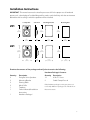
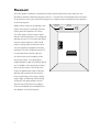
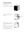
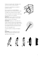
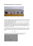
251
261
Designer Series
In-Wall Speaker Systems
Specifications
251
261
Frequency Response (±3dB)
66–20,000Hz
58 –20,000Hz
Recommended Amplifier Power
10 –100 watts
10 –100 watts
Nominal Impedance
8 ohms
8 ohms
Sensitivity [1 watt (2.83v) at 1m]
89dB
90dB
Tweeter
3
3
Bass Unit
51⁄4" (135mm) copolymer
61⁄2" (165mm) copolymer
Crossover Frequency
6500Hz
6200Hz
External Dimensions (HxW)
9 1⁄2 x 6 3⁄4" (241 x 171mm)
10 9⁄16 x 7 3⁄4" (268 x 197mm)
Mounting Hole Cutout (HxW)
8 3⁄4 x 5 3⁄4" (223 x 146mm)
9 7⁄8 x 7 1⁄8" (251 x 181mm)
Mounting Depth (from surface)
2 5⁄8" (67mm)
2 7⁄8" (73mm)
⁄4" (19mm) dome
⁄4" (19mm) dome
Description
Boston Designer Series speaker systems are designed to be as accurate, clean, and musical as our
free-standing speakers. The unobtrusive, flush-mount design makes them ideal for installation
in walls or ceilings of rooms where space or decor make conventional speakers undesirable or
inappropriate. They can also be used for the front and/or rear channels in a home theater system.
The front surface is provided with a matte white finish. The speaker can be installed as is or can be
painted to match the room environment, using the supplied painting mask. The speaker grille is
removable, and is made of epoxy-painted galvanized steel.
Their smooth, detailed sound comes from two highly refined driver elements: a copolymer bass unit
with butyl rubber surround for powerful bass and natural midrange, and a 3⁄4-inch dome tweeter that
provides outstanding clarity and articulation. The tweeter and bass unit are mounted close together
in a point-source configuration for excellent imaging and extremely broad, uniform dispersion. This
is important, because wide dispersion gives you the flexibility to install the speakers where they look
the best (high on the walls, for example), yet still project clear sound throughout the listening area.
Both drivers are built in Boston’s state-of-the-art production facility to be within ±1dB of the laboratory reference, perhaps the industry’s tightest tolerance.
2
Installation Instructions
IMPORTANT: This manual assumes the installer possesses skill in the proper use of hand and
power tools, a knowledge of local building and fire codes, and a familiarity with the environment
behind the wall or ceiling in which the speakers will be installed.
Loudspeaker
Side View
Mounting Bracket
Mounting Hole
251
9 5⁄ 8"
(143mm)
9 1⁄ 2"
(241mm)
6 3⁄ 4"
(171mm)
8 3⁄4"
(223mm)
2 5⁄ 8"
(67mm)
5 5⁄ 8"
(143mm)
5 3⁄ 4"
(146mm)
261
10 1⁄ 2"
(267mm)
10 9⁄ 16"
(268mm)
7 3⁄ 4"
(197mm)
9 7⁄ 8"
(251mm)
7 1⁄ 8"
(181mm)
6 11⁄ 16"
(170mm)
2 7⁄ 8"
(73mm)
Examine the contents of the package and verify that it contains the following:
Hardware Package* Contents:
Quantity
Description
Quantity
Description
2
Designer Series Speakers
12
8-32 x 2" Screw
2
Mounting Bracket
2
Cable Clamp–Press-In
2
Painting Mask
2
Metal Grille
1
Template
1
Owner’s Manual/Installation
* If the hardware package is missing any items or is
not found, additional packages are available from
Boston Acoustics.
Instructions
1
Hardware Package*
3
Placement
Since the speaker installation is permanent and the furniture placement may not be, the user
should first determine the best long-term location — one that will accommodate future relocation
of the furniture in the room, while still allowing for an unobstructed sound path from the speakers
to the listening area.
Within reason, wherever the speakers look
right is where they’ll sound right. For best
results, place the speakers 6 to 10 feet
(1.8–3.3m) apart, so they form a triangle
with the main listening area. Try to keep the
speakers at least 12 to 18 inches (30–45cm)
from the nearest reflective surface (side
walls or ceiling). When used near a television, the speakers should be mounted a
minimum of 6 inches (150mm) from the TV
to avoid interference with the picture.
As a final check on the suitability of the
mounting location, it’s a good idea to
temporarily place a pair of small box speakers, if available, at the mounting locations
chosen for the system. This will give the
listener an approximate idea of what the
speakers will sound like in that location.
Listen for pleasing stereo image, realistic
stage height, or balanced surround-field
coverage (if using the speakers as rearchannel surrounds). Note if any objects
in the room impede the sound path from
the speakers to the listening area.
4
12-18 inches
(30-45cm)
6-10 feet
(1.8-3.3m)
Painting the Speakers
If you intend to paint the speakers, it’s best to
do so before installation.
1. Remove the speaker grille. Carefully pry at
each corner with an awl or a small screwdriver.
2. Use the form-fitting painting mask provided
to paint the housing. Cover the slots with
masking tape.
Use masking tape
to cover slots
Bosto
n
3. After painting, remove the mask by carefully
inserting a screwdriver into the slots. Do not
puncture the drivers behind the mask with the
screwdriver.
4. When painting the grilles, be certain that the
paint does not fill the perforated holes in the
metal. If using spray paint, use two thin coats.
Bosto
n
If using house paint or other canned paint, thin
the paint to avoid filling the holes.
5
Preparing for Installation
Map out the wiring paths from the speakers to the amplifier. We recommend 18-gauge wire for
runs up to 25 feet, and 16-gauge or thicker for longer runs. Be sure the speaker wire does not rest
or rub against any sharp or pointed objects.
The speakers should be mounted on a flat surface to form a good seal between the speaker flange
and the mounting surface.
Each speaker is 8 ohms nominal. When connecting more than two speakers per amplifier channel,
you should use series/parallel wiring or line transformers. In all cases, make certain that the total
impedance does not fall below the amplifier’s minimum rating. If you are not sure, contact your
Boston Acoustics dealer.
Use the cable clamp supplied to secure the speaker wire to the housing. Press the clamp into one
of the holes on the printed circuit board.
You Will Need
1. A utility knife, an electric jigsaw, or another means of cutting a hole in the mounting surface.
2. Phillips and flat-blade screwdrivers.
3. A wire cutter or stripper for preparing the speaker wires.
4. An awl or a small screwdriver to remove the speaker grille.
With the hardware supplied, the speaker can be installed in existing walls and ceilings from
⁄ " (9.5mm) to 11⁄ 2" (38mm) thick. For thinner walls, you will need to use spacers (not provided)
38
for the mounting bracket. In walls greater than 11⁄ 2" (38mm) thick, you will need longer screws.
Installation
1. Make a cutout using the supplied template.
BostonAcoustics
BostonAcoustics
251
261
HOLE CUTTING TEMPLATE
Cut hole to exact size of template. For details, see page 6 of installation instructions.
8 3⁄4"
(223mm)
HOLE CUTTING TEMPLATE
9 7⁄ 8"
(251mm)
5 3⁄4"
(146mm)
Cut hole to exact size of template. For details, see page 6 of installation instructions.
7 1⁄ 8"
(181mm)
2. Run the wire from the amplifier to the cutout. Allow an extra foot of wire at the
cutout. Strip 1⁄ 2" (12mm) off the wire, and tightly twist the wire strands together.
6
3. Remove the speaker grille. Carefully pry each
corner with an awl or a small screwdriver.
4. Prepare the speaker/bracket assembly for
installation as shown.
For new construction, an optional bracket
(Model 35UB for the 251, Model 36CB for the 261)
is available from your Boston Acoustics dealer.
5. Route the speaker wire through the cable clamp
and connect the wire to the speaker.
WARNING: To prevent electrical shock hazard,
always switch off the amplifier or receiver when
making connections to the speaker.
IMPORTANT: Typically, one side of the wire is
smooth. Connect this side to the – (black) speaker
terminal. The other side has a rib or stripe. Connect
this to the + (red) speaker terminal. Connect wire
at the amplifier in the same way. Failure to do so
will result in degraded sound.
6. Install the speaker according to the diagram
below.
IMPORTANT: Do not overtighten the screws.
Doing so will break the frame and/or make it
impossible to insert the grille.
7
Listening Levels and Power-Handling
The power recommendation for the speakers assumes that you will operate the amplifier in a way
that will not produce distortion. Even our rugged speakers can be damaged by an amplifier if it is
producing distortion.
If you hear a harsh, gritty noise, turn down the volume. Prolonged or repeated operation of your
speaker with a distorted signal from the amplifier can cause damage that is not covered by the
warranty.
Limited Warranty
For one year from the date of purchase, Boston Acoustics will repair for the original owner any
defect in materials or workmanship that occurs in normal use, without charge for parts and labor.
Your responsibilities are to use the system according to the instructions supplied, to provide safe
and secure transportation to an authorized Boston Acoustics service representative, and to present
proof of purchase in the form of your sales slip when requesting service.
Excluded from this warranty is damage that results from abuse, misuse, accidents, shipping, or repairs
or modifications by anyone other than an authorized Boston Acoustics service representative.
This warranty is void if the serial number has been removed or defaced.
This warranty gives you specific legal rights, and you may also have other rights which vary from
state to state.
If Service Seems Necessary
First, contact the retailer from whom you purchased the speakers. If that is not possible, write to:
Boston Acoustics, Inc. 300 Jubilee Drive Peabody, MA 01960 U.S.A.
We will promptly advise you of what action to take. If it is necessary to return your speaker to the
factory, please ship it prepaid. After it has been repaired, we will return it freight prepaid in the
U.S. and Canada.
300 Jubilee Drive
Peabody, MA 01960 U.S.A.
978.538.5000
Boston and Boston Acoustics are registered
trademarks of Boston Acoustics, Inc.
Specifications subject to change without notice.
© 1998 Boston Acoustics, Inc.
42-955-0