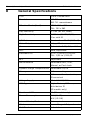
1
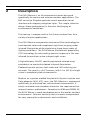
EX14 Marine Camera
EX14 Series
en
Instruction Manual
EX14 Marine Camera
Table of Contents | en
3
Table of Contents
1
Safety
4
1.1
Important safety instructions
4
1.2
Safety precautions
4
1.3
Important notices
5
1.4
Customer Support and Service
2
Description
12
2.1
Unpacking
13
2.1.1
Parts List
13
2.1.2
Items Required for Installation
13
3
Initial Preparations
14
3.1
Installation Guidelines
14
4
Camera Mounting
15
4.1
Mounting instructions
15
5
Camera Connections
17
11
5.1
Camera Adjustments
18
5.2
LED Array Adjustments
19
6
Camera Configuration
20
6.1
OSD Menus
20
6.1.1
Exposure Menu
21
6.1.2
Color Menu
23
6.1.3
Day/Night Menu
26
6.1.4
Function Menu
27
6.1.5
Privacy Menu
32
6.1.6
Set Up Menu
34
7
Troubleshooting
39
8
General Specifications
40
Bosch Security Systems, Inc.
Instruction Manual
F.01U.240.878 | 1.0 | 2011.07
4
en | Safety
EX14 Marine Camera
1
Safety
1.1
Important safety instructions
Read, follow, and retain all of the following safety instructions.
Heed all warnings on the unit and in the operating instructions
before operating the unit.
1.
Read these instructions.
2.
Keep this instruction.
3.
Heed all warnings.
4.
Follow all instructions.
5.
Clean only with dry cloth.
6.
Do not block any ventilation openings. Install in
7.
Do not install near any heat sources such as radiators, heat
accordance with manufacturer’s instructions.
registers, stoves or other apparatus (including amplifiers)
that produce heat.
8.
Protect the power cord from being walked on or pinched
particularly at plugs, convenience receptacles, and the
power where they exit from the apparatus.
9.
Only use attachments/accessories specified by the
manufacturer.
10. Refer all servicing to qualified service personnel. Servicing
is required when the apparatus has been damaged in a
way, such as power-supply cord or plug is damaged, liquid
has been spilled or objects have fallen into the apparatus,
does not operate normally, or has dropped. When
servicing, power shall be disconnected.”
F.01U.240.878 | 1.0 | 2011.07
Instruction Manual
Bosch Security Systems, Inc.
EX14 Marine Camera
1.2
Safety | en
5
Safety precautions
DANGER!
High risk: This symbol indicates an imminently hazardous
situation such as “Dangerous Voltage” inside the product.
If not avoided, this will result in an electrical shock, serious
bodily injury, or death.
WARNING!
Medium risk: Indicates a potentially hazardous situation.
If not avoided, this could result in minor or moderate bodily
injury.
CAUTION!
Low risk: Indicates a potentially hazardous situation.
If not avoided, this could result in property damage or risk of
damage to the unit.
1.3
Important notices
Accessories - Do not place this unit on an unstable stand,
tripod, bracket, or mount. The unit may fall, causing serious
injury and/or serious damage to the unit. Use only with the
cart, stand, tripod, bracket, or table specified by the
manufacturer. When a cart is used, use caution and care when
moving the cart/apparatus combination to avoid injury from
tip-over. Quick stops, excessive force, or uneven surfaces may
cause the cart/unit combination to overturn. Mount the unit
per the manufacturer's instructions.
Coax grounding:
–
Ground the cable system if connecting an outside cable
–
Connect outdoor equipment to the unit's inputs only after
system to the unit.
this unit has had its grounding plug connected to a
grounded outlet or its ground terminal is properly
connected to a ground source.
Bosch Security Systems, Inc.
Instruction Manual
F.01U.240.878 | 1.0 | 2011.07
6
en | Safety
–
EX14 Marine Camera
Disconnect the unit's input connectors from outdoor
equipment before disconnecting the grounding plug or
grounding terminal.
–
Follow proper safety precautions such as grounding for
any outdoor device connected to this unit.
U.S.A. models only - Section 810 of the National Electrical Code,
ANSI/NFPA No.70, provides information regarding proper
grounding of the mount and supporting structure, grounding of
the coax to a discharge unit, size of grounding conductors,
location of discharge unit, connection to grounding electrodes,
and requirements for the grounding electrode.
Electronic Surveillance - This device is intended for use in
public areas only. U.S. federal law strictly prohibits
surreptitious recording of oral communications.
Environmental statement - Bosch has a strong commitment
towards the environment. This unit has been designed to
respect the environment as much as possible.
Electrostatic-sensitive device - Use proper CMOS/MOS-FET
handling precautions to avoid electrostatic discharge.
NOTE: Wear required grounded wrist straps and observe proper
ESD safety precautions when handling the electrostaticsensitive printed circuit boards.
Fuse rating - For security protection of the device, the branch
circuit protection must be secured with a maximum fuse rating
of 16A. This must be in accordance with NEC800 (CEC Section
60).
Moving - Disconnect the power before moving the unit. Move
the unit with care. Excessive force or shock may damage the
unit.
Outdoor signals - The installation for outdoor signals, especially
regarding clearance from power and lightning conductors and
transient protection, must be in accordance with NEC725 and
NEC800 (CEC Rule 16-224 and CEC Section 60).
Permanently connected equipment - Incorporate a readily
accessible disconnect device in the building installation wiring.
Pluggable equipment - Install the socket outlet near the
equipment so it is easily accessible.
F.01U.240.878 | 1.0 | 2011.07
Instruction Manual
Bosch Security Systems, Inc.
EX14 Marine Camera
Safety | en
7
Power resupply - If the unit is forced to power down due to
exceeding the specified operating temperatures, disconnect
the power cord, wait for at least 30 seconds, and then
reconnect the power cord.
Power lines - Do not locate the camera near overhead power
lines, power circuits, or electrical lights, nor where it may
contact such power lines, circuits, or lights.
SELV
All the input/output ports are Safety Extra Low Voltage (SELV)
circuits. SELV circuits should only be connected to other SELV
circuits.
Because the ISDN circuits are treated like telephone-network
voltage, avoid connecting the SELV circuit to the Telephone
Network Voltage (TNV) circuits.
Video loss - Video loss is inherent to digital video recording;
therefore, Bosch Security Systems cannot be held liable for any
damage that results from missing video information. To
minimize the risk of lost digital information, Bosch Security
Systems recommends multiple, redundant recording systems,
and a procedure to back up all analog and digital information.
Bosch Security Systems, Inc.
Instruction Manual
F.01U.240.878 | 1.0 | 2011.07
8
en | Safety
EX14 Marine Camera
FCC & ICES Information
(U.S.A. and Canadian Models Only)
This equipment has been tested and found to comply with the
limits for a Class B digital device, pursuant to part 15 of the
FCC Rules. These limits are designed to provide reasonable
protection against harmful interference in a residential
installation. This equipment generates, uses, and can radiate
radio frequency energy and, if not installed and used in
accordance with the instructions, may cause harmful
interference to radio communications. However, there is no
guarantee that interference will not occur in a particular
installation. If this equipment does cause harmful interference
to radio or television reception, which can be determined by
turning the equipment off and on, the user is encouraged to try
to correct the interference by one or more of the following
measures:
–
reorient or relocate the receiving antenna;
–
increase the separation between the equipment and
receiver;
–
connect the equipment into an outlet on a circuit different
–
consult the dealer or an experienced radio/TV technician
from that to which the receiver is connected;
for help.
Intentional or unintentional modifications, not expressly
approved by the party responsible for compliance, shall not be
made. Any such modifications could void the user's authority to
operate the equipment. If necessary, the user should consult
the dealer or an experienced radio/television technician for
corrective action.
The user may find the following booklet, prepared by the
Federal Communications Commission, helpful: How to Identify
and Resolve Radio-TV Interference Problems. This booklet is
available from the U.S. Government Printing Office,
Washington, DC 20402, Stock No. 004-000-00345-4.
F.01U.240.878 | 1.0 | 2011.07
Instruction Manual
Bosch Security Systems, Inc.
EX14 Marine Camera
Safety | en
9
INFORMATIONS FCC ET ICES
(modèles utilisés aux États-Unis et au Canada uniquement)
Suite à différents tests, cet appareil s'est révélé conforme aux
exigences imposées aux appareils numériques de classe B, en
vertu de la section 15 du règlement de la Commission fédérale
des communications des États-Unis (FCC), et en vertu de la
norme ICES-003 d'Industrie Canada. Ces exigences visent à
fournir une protection raisonnable contre les interférences
nuisibles lorsque l'appareil est utilisé dans le cadre d'une
installation résidentielle. Cet appareil génère, utilise et émet
de l'énergie de radiofréquences et peut, en cas d'installation ou
d'utilisation non conforme aux instructions, engendrer des
interférences nuisibles au niveau des radiocommunications.
Toutefois, rien ne garantit l'absence d'interférences dans une
installation particulière. Il est possible de déterminer la
production d'interférences en mettant l'appareil
successivement hors et sous tension, tout en contrôlant la
réception radio ou télévision. L'utilisateur peut parvenir à
éliminer les interférences éventuelles en prenant une ou
plusieurs des mesures suivantes :
–
Modifier l'orientation ou l'emplacement de l'antenne
réceptrice;
–
–
Éloigner l'appareil du récepteur;
Brancher l'appareil sur une prise située sur un circuit
différent de celui du récepteur;
–
Consulter le revendeur ou un technicien qualifié en radio/
télévision pour obtenir de l'aide.
Toute modification apportée au produit, non expressément
approuvée par la partie responsable de l'appareil, est
strictement interdite. Une telle modification est susceptible
d'entraîner la révocation du droit d'utilisation de l'appareil.
La brochure suivante, publiée par la Commission fédérale des
communications (FCC), peut s'avérer utile : How to Identify and
Resolve Radio-TV Interference Problems (Comment identifier et
résoudre les problèmes d’interférences de radio et de télévision).
Cette brochure est disponible auprès du U.S. Government
Bosch Security Systems, Inc.
Instruction Manual
F.01U.240.878 | 1.0 | 2011.07
10
en | Safety
EX14 Marine Camera
Printing Office, Washington, DC 20402, États-Unis, sous la
référence n° 004-000-00345-4.
DANGER!
CSA Certified/UL Listed Class 2 adaptors must be use in order
to comply with electrical safety standards.
Only qualified personnel shall install any Bosch Extreme series
camera and conform to all local safety codes. Bosch Security
Systems, Inc. will not be responsible for injuries or damages
resulting from the improper installation or use of any
equipment sold by Bosch, their agents, distributors or dealers
Disclaimer
Underwriter Laboratories Inc. (“UL”) has not tested the
performance or reliability of the security or signaling aspects of
this product. UL has only tested fire, shock and/or casualty
hazards as outlined in UL's Standard(s) for Safety for Closed
Circuit Television Equipment, UL 2044. UL Certification does not
cover the performance or reliability of the security or signaling
aspects of this product.
UL MAKES NO REPRESENTATIONS, WARRANTIES, OR
CERTIFICATIONS WHATSOEVER REGARDING THE
PERFORMANCE OR RELIABILITY OF ANY SECURITY OR
SIGNALING RELATED FUNCTIONS OF THIS PRODUCT.
Disclaimer
Underwriter Laboratories Inc. (“UL”) has not tested the
performance or reliability of the security or signaling aspects of
this product. UL has only tested fire, shock and/or casualty
hazards as outlined in UL's Standard(s) for Safety for Information
Technology Equipment, UL 60950-1. UL Certification does not
cover the performance or reliability of the security or signaling
aspects of this product.
UL MAKES NO REPRESENTATIONS, WARRANTIES, OR
CERTIFICATIONS WHATSOEVER REGARDING THE
PERFORMANCE OR RELIABILITY OF ANY SECURITY OR
SIGNALING-RELATED FUNCTIONS OF THIS PRODUCT.
F.01U.240.878 | 1.0 | 2011.07
Instruction Manual
Bosch Security Systems, Inc.
EX14 Marine Camera
Safety | en
11
Copyright
This manual is the intellectual property of Bosch Security
Systems and is protected by copyright.
All rights reserved.
Trademarks
All hardware and software product names used in this
document are likely to be registered trademarks and must be
treated accordingly.
NOTE!
This manual has been compiled with great care and the
information it contains has been thoroughly verified. The text
was complete and correct at the time of printing. The ongoing
development of the products may mean that the content of the
user guide can change without notice. Bosch Security Systems
accepts no liability for damage resulting directly or indirectly
from faults, incompleteness or discrepancies between the user
guide and the product described.
More information
For additional information, please contact the Bosch Security
Systems location nearest you or visit our web site at
www.boschsecuritysystems.com
Bosch Security Systems, Inc.
Instruction Manual
F.01U.240.878 | 1.0 | 2011.07
12
en | Safety
1.4
EX14 Marine Camera
Customer Support and Service
If this unit needs service, contact the nearest Bosch Security
Systems Service Center for authorization to return and shipping
instructions.
Service Centers
USA
Repair Center
Telephone: 800-366-2283
Fax: 800-366-1329
E-mail: [email protected]
Customer Service
Telephone: 888-289-0096
Fax: 585-223-9180
E-mail: [email protected]
Technical Support
Telephone: 800-326-1450
Fax: 585-223-3508 or 717-735-6560
E-mail: [email protected]
Canada
Telephone: 514-738-2434
Fax: 514-738-8480
Europe, Middle East, Africa Region
Repair Center
Please contact your local distributor or Bosch sales office. Use
this link:
http://www.boschsecurity.com/startpage/html/europe.htm
Asia Region
Repair Center
Please contact your local distributor or Bosch sales office. Use
this link:
http://www.boschsecurity.com/startpage/html/asia_pacific.htm
Warranty and additional information
For additional information and warranty queries, please contact
your Bosch Security Systems representative or visit our website
at www.boschsecurity.com.
F.01U.240.878 | 1.0 | 2011.07
Instruction Manual
Bosch Security Systems, Inc.
12
2
en | Description
EX14 Marine Camera
Description
The EX14 Marine is an all-environment camera designed
specifically for marine and extreme weather applications. The
940 nm active IR option provides covert operation to not
interfere with shipping navigation lights. The simple, effective
design allows performance in the most challenging of
environmental conditions.
The housing is compact with a 4 to 9 mm varifocal lens for a
variety of marine applications.
The EX14 Marine incorporates mechanical filter technology for
vivid daytime color and exceptional night-time imaging under
infrared illumination while maintaining sharp focus under all
lighting conditions. The EX14 Marine also features proprietary
CCD technology for outstanding spectral response in the near
infrared for excellent active-infrared night vision.
A high-efficiency 18-LED spatially optimized infrared array
contributes to evenly-distributed infrared illumination.
Photocell-control ensures that video and LED switching are
accurate. The result is a 24/7 camera, with 12 m (40 ft) of night
vision in completely dark environments.
Made of an injection-molded Acrylonitrile Styrene Acrylate and
Polycarbonate (ASA +PC) resin, the EX14 Marine is engineered
specifically to withstand hot, cold and wet environments. A
totally insulated inner chamber eliminates the requirement for
internal heaters and blowers. Compliant to IP66 and NEMA 4X,
the EX14 Marine is ready for deployment in the worlds harshest
environments. Features and easy-access camera compartment
for easy camera/lens adjustments and installation.
F.01U.240.878 | 1.0 | 2011.07
Instruction Manual
Bosch Security Systems, Inc.
EX14 Marine Camera
Description | en
13
Rugged, compact, power protected and extreme
weathersealed, the EX14 Marine is an ideal camera for harsh
extreme environments in day or dark conditions. The EX14
Marine comes complete with a nylon wall bracket for a quick
and easy installation.
2.1
Unpacking
Care should be taken when unpacking the shipped unit. Check
the parts list and confirm all items have been located. Inspect
the equipment thoroughly to ensure nothing was damaged in
transit.
Contact your Bosch Security Systems Service Center if a
problem is noted.
2.1.1
Parts List
These items are supplied with the unit:
2.1.2
–
EX14 Marine Camera
–
Two Hex keys
–
Two bolts for mounting camera to bracket
–
Mounting bracket
–
Installation Manual
Items Required for Installation
The installer must supply these items:
–
Mounting hardware
–
Tools
–
Wiring
Bosch Security Systems, Inc.
Instruction Manual
F.01U.240.878 | 1.0 | 2011.07
14
en | Initial Preparations
3
EX14 Marine Camera
Initial Preparations
1.
Determine the operating voltage at the installation site.
The camera’s Voltage Regulator Board accepts 12-24 VDC/
VAC input without change to internal connections
2.
Determine the optimum mounting location for the camera.
See Section 4 Camera Mounting, page 15.
3.
All cameras have been tested and pre-focused with
telephoto setting as factory default prior to shipment. If
any adjustment needed, it is advisable to check the
camera’s operation before installation.
3.1
Installation Guidelines
–
Refer to Section 4 Camera Mounting, page 15, for
installation instructions.
–
It is important that these steps are followed in numerical
order.
–
This installation must be made by a qualified service
person and must conform to all local codes.
F.01U.240.878 | 1.0 | 2011.07
Instruction Manual
Bosch Security Systems, Inc.
EX14 Marine Camera
4
Camera Mounting | en
15
Camera Mounting
WARNING!
IMPORTANT MOUNTING INSTRUCTIONS
THIS APPARATUS MUST BE SECURELY ATTACHED TO THE
WALL IN ACCORDANCE WITH THE INSTALLATION
INSTRUCTIONS. FAILURE TO FOLLOW INSTALLATION
INSTRUCTIONS MAY RESULT IN INJURY.
CAUTION!
Ensure the selected location is protected from falling objects,
accidental contact with moving objects, and unintentional
interference from personnel. Follow all applicable building
codes.
Follow these mounting guidelines:
1.
Choose a location where the apparatus cannot be easily
interfered with, either intentionally or accidentally.
2.
Select a mounting surface capable of supporting the
combined weight of the camera and its mounting hardware
under all expected conditions of vibration and
temperature.
3.
Secure all cabling.
4.
Installation should only be performed by skilled personnel.
Hardware required for Wall Mount
–
Two (2) #10 x 2 in. wood screws
–
Two (2) flat washers for #10 screws
Tools required
–
Drill
–
Stud finder
–
1/8 in. drill bit
–
Screwdriver
Bosch Security Systems, Inc.
Instruction Manual
F.01U.240.878 | 1.0 | 2011.07
16
en | Camera Mounting
4.1
EX14 Marine Camera
Mounting instructions
The camera is intended to be securely mounted to a wall using
the mounting bracket supplied with the enclosure. The camera
has been evaluated for wall mounting using 2 in. long #10 wood
screws with washers secured into a 2 x 4 stud under 1/2 in. of
drywall.
1.
Locate a stud in the wall and mark outside edges of stud.
2.
Using the wall mount bracket as a template, align the
mounting holes with the center of the stud.
3.
Mark points on the wall in the center of the holes where
the mounting screws are positioned.
4.
Remove the wall mount bracket and using a 1/8 in. drill bit.
Drill pilot holes at the marked points.
5.
Align the holes in the bracket with the holes drilled in the
6.
Using a screwdriver secure the wall mount bracket by
wall.
screwing the #10 screws and washers securely into the
stud.
7.
Mounting is complete.
(Camera has not been evaluated for safety requirements
using other mounting kits.)
F.01U.240.878 | 1.0 | 2011.07
Instruction Manual
Bosch Security Systems, Inc.
EX14 Marine Camera
5
Camera Connections | en
17
Camera Connections
The camera unit is pre-connected with an electrically isolated
power board for 24 VAC or 12 VDC operation with no wiring
change or wiring polarity. Input voltage is 12 VDC to 24 VDC for
DC input. The AC input range is 12 VAC to 24 VAC.
Please refer to the following steps for camera power/video
cable connections. The Camera is designed for use with a
power/video composite cable with a diameter of 11/64 in. to
15/32 in. (4.4 mm to 11.9 mm), power wires should be at least
18 AWG.
Follow these steps in sequence:
1.
Remove the two bolts at the bottom of the housing with
the supplied hex key and open the enclosure.
2.
Strip back an appropriate amount of the cable jacket, if
necessary and feed the composite cable through the gland
into the housing.
3.
Connect the video and power wires to the terminal block
as shown below.
1
2
3
4
Bosch Security Systems, Inc.
Video
Video Ground
Power In +
Power In -
Yellow wire
Black wire
Red wire
Black wire
Instruction Manual
F.01U.240.878 | 1.0 | 2011.07
18
en | Camera Connections
EX14 Marine Camera
4.
Remove the desiccant from the plastic bag.
5.
Place the desiccant into the enclosure on the side
opposite of the cable connections.
6.
Tighten the nut of the gland to 1.3 NM torque setting and
ensure it is sealed well.
7.
Perform any required adjustments as detailed in
Section 5.1 Camera Adjustments, page 18 and
Section 5.2 LED Array Adjustments, page 19.
8.
Close the enclosure and make sure the sealing gasket is in
place and the round tab at the top of the window locks
into the top inside of the housing.
5.1
Camera Adjustments
This section contains instruction for adjusting the Focus and
Zoom settings.
1.
Loosen and tilt back the camera’s top cover to access the
2.
Loosen the lens setscrews for focus/zoom adjustments.
lens for adjustment.
See Figure 5.1 on Page 18.
–
The setscrew for N --- ∞ is used for image focus
(item 1, below).
–
The setscrew for T--- W is used for telephoto or wide-
W
T
N
angle settings. (item 2, below)
3.
Re-tighten the setscrews after focus adjustments have
been completed.
F.01U.240.878 | 1.0 | 2011.07
Instruction Manual
Bosch Security Systems, Inc.
EX14 Marine Camera
5.2
Camera Connections | en
19
LED Array Adjustments
The LED Array sensitivity has been set at the factory before
shipment. For photocell sensitivity adjustment refer to the
following illustration:
1
2
Power to LED Array
Photocell Adjustment
–
3
4
CW - Increase sensitivity
–
CCW - Decrease sensitivity
12 V Enable
Power Input
NOTE: Use a Neutral Density filter or Infrared Pass filter to
cover the lens during focusing to simulate low light conditions
on scene for correct 24 hour focusing. The camera should be
focused with the lens iris fully opened to simulate the worst
possible depth of field. Using a Neutral Density filter of Infrared
Pass filter will ensure the iris is fully open for correct setup and
adjustment.
Bosch Security Systems, Inc.
Instruction Manual
F.01U.240.878 | 1.0 | 2011.07
20
en | Camera Configuration
6
EX14 Marine Camera
Camera Configuration
Camera configuration is performed through the On-screen
Display (OSD) menu. To access these menus:
1.
Open the EX14 camera housing cap to access the OSD
controls.
2.
3.
Press the joystick button down to enter the OSD menu.
Follow the instructions below to make camera
adjustments.
6.1
OSD Menus
The main Camera Operation menu allows you to set the
following parameters:
Figure 6.1
Main Camera Operation Menu
The following sections provide details for each parameter on
each sub-menu.
F.01U.240.878 | 1.0 | 2011.07
Instruction Manual
Bosch Security Systems, Inc.
EX14 Marine Camera
6.1.1
LENS
Camera Configuration | en
21
Exposure Menu
Select the type of lens: MANUAL or DC.
Note: The default setting is DC. If you change this setting
undesired operation may occur.
MANUAL
Select for manual iris control. Adjust the brightness of the
screen by configuring the ELC level.
DC
Select for automatic iris control. Adjust the offset brightness
of the screen by configuring the DC level.
Bosch Security Systems, Inc.
Instruction Manual
F.01U.240.878 | 1.0 | 2011.07
22
en | Camera Configuration
EX14 Marine Camera
E.SHUTTER Select either AUTO or FIXED control for the electronic
shutter.
Note: The default setting is AUTO. If you change this setting
undesired operation may occur.
AUTO
Set for complete automatic operation of the electronic
shutter, only available when lens iris control is set to Manual.
FIXED
Set the desired minimum shutter speed. Ten levels are
available.
1/50s(PAL), 1/60s(NTSC), 1/100s,1/250s, 1/500s, 1/1000s,
1/2000s, 1/4000s, 1/10000s, 1/100000s)
F.01U.240.878 | 1.0 | 2011.07
Instruction Manual
Bosch Security Systems, Inc.
EX14 Marine Camera
Camera Configuration | en
23
BLC (Back Light Compensation)
Change the BLC setting when there is a strong backlight in
the scene to get a uniform image.
Select BLC ON to adjust the BLC level 5 sections (TOP /
DOWN / CENTER / RIGHT / LEFT). Increase the level in areas
desired to become brighter for compensation.
AGC (Automatic Gain Control)
This function automatically adjusts video gain to enhance the
picture in darker scenes. AGC is adjustable within the range:
OFF - 36 dB.
Bosch Security Systems, Inc.
Instruction Manual
F.01U.240.878 | 1.0 | 2011.07
24
en | Camera Configuration
6.1.2
EX14 Marine Camera
Color Menu
WHITE BALANCE CONTROL
Adjusts the screen color in accordance with the type of
ambient light on scene. Use the following parameters:
–
AWC: Use this for color temperatures below 2500°C and
over 9500°C (indoors)
–
ATW: Use this for color temperatures between 2500°C
–
MANUAL: The white balance is manually controlled.
–
PUSH LOCK: Adjusts the white balance automatically for
and 9500 °C (outdoors)
the current light on scene.
F.01U.240.878 | 1.0 | 2011.07
Instruction Manual
Bosch Security Systems, Inc.
EX14 Marine Camera
Camera Configuration | en
25
MANUAL
Adjusts RED or BLUE in accordance with the type of ambient
light on scene.
GAIN CONTROL
Select the desired gain value. The higher the gain level, the
more the scene displays that color.
–
R-Y GAIN: Adjusts the RED color .
–
B-Y GAIN: Adjusts the BLUE color.
Bosch Security Systems, Inc.
Instruction Manual
F.01U.240.878 | 1.0 | 2011.07
26
en | Camera Configuration
6.1.3
EX14 Marine Camera
Day/Night Menu
AUTO/COLOR/BW
This function determines when the camera switches modes:
–
AUTO: The camera automatically switches between day
and night
mode depending on the light level.
Note: The following default setting should not be
changed: Day/Night = Auto
–
COLOR: The camera stays in day mode.
–
B/W: The camera stays in night mode.
–
BURST SIGNAL: If ON, the screen shows a color burst
while switching to
day mode from night mode.
–
SET LEVEL: Not adjustable.
–
READ TIME: The switching time delay in AUTO mode for
when the scene suddenly gets darker or brighter,
adjustable from 3 secs to 12 secs.
F.01U.240.878 | 1.0 | 2011.07
Instruction Manual
Bosch Security Systems, Inc.
EX14 Marine Camera
6.1.4
Camera Configuration | en
27
Function Menu
MIRROR
If ON is selected, the horizontal image on the screen is
reversed.
SHARPNESS
Adjusts the image sharpness.
Bosch Security Systems, Inc.
Instruction Manual
F.01U.240.878 | 1.0 | 2011.07
28
en | Camera Configuration
EX14 Marine Camera
GAMMA
Adjusts the Gamma level; selectable in three levels: 0.45,
0.6, 1.0
SLD (Side Light Compensation)
Select this mode when the corner of the screen is darker
than the center.
F.01U.240.878 | 1.0 | 2011.07
Instruction Manual
Bosch Security Systems, Inc.
EX14 Marine Camera
Camera Configuration | en
29
HME (High Light Masking Exposure)
This function masks the bright areas on the screen. The
brightness of HME is adjustable. As the level of HME is
increases, the masking area increases.
DRC (Dynamic Range Compensation)
This function is to compensate darker images when different
exposures are in one scene.
MOTION DETECTION
Allows you to detect the movement of an object in 64
different areas of the screen, and to display an alarm on the
screen.
Select or deselect blue areas with the joystick, only the blue
areas are monitored for movement.
Bosch Security Systems, Inc.
Instruction Manual
F.01U.240.878 | 1.0 | 2011.07
30
en | Camera Configuration
EX14 Marine Camera
–
ALL SET: Sets the entire screen for motion detection.
–
ALL CLEAR: Clears the entire screen for motion
detection.
F.01U.240.878 | 1.0 | 2011.07
Instruction Manual
Bosch Security Systems, Inc.
EX14 Marine Camera
–
Camera Configuration | en
31
SENSITIVITY LEVEL: As the sensitivity level increases,
smaller movements are detected.
–
SHOW INDI: The motion detected indicator can be
selected as icon, trace or off.
–
DELAY OUT: The alarm signal display on the screen is
delayed from 1sec to 15 sec.
Bosch Security Systems, Inc.
Instruction Manual
F.01U.240.878 | 1.0 | 2011.07
32
en | Camera Configuration
6.1.5
EX14 Marine Camera
Privacy Menu
PRIVACY MASKING ZONE
This function sets certain areas of the screen to be hidden.
Four (4) masking zones are available.
–
MASK 1: Adjust the masking area by using the joystick.
–
MASK 2: Adjust the masking area by using the joystick.
–
MASK 3: Adjust the masking area by using the joystick.
–
MASK 4: Adjust the masking area by using the joystick.
If SET WINDOW is selected, the cell is displayed on the
screen and then adjusted by moving the joystick UP / DOWN
/ RIGHT / LEFT. Once desired area is covered press the
joystick in until mask area is black then move the joystick
any direction to return to the previous screen.
F.01U.240.878 | 1.0 | 2011.07
Instruction Manual
Bosch Security Systems, Inc.
EX14 Marine Camera
Camera Configuration | en
33
COLOR SET
This function is to select the color of the masking cells.
6.1.6
Set Up Menu
CAMERA ID
Enter a camera ID as a unique identifier.
Bosch Security Systems, Inc.
Instruction Manual
F.01U.240.878 | 1.0 | 2011.07
34
en | Camera Configuration
EX14 Marine Camera
TITLE DISPLAY
Camera title is displayed on the screen when a value is
entered.
–
TITLE EDIT: Selects the value.
–
TITLE RESET: Clears the title.
–
TITLE POSITION SELECTION: Sets area that displays
the title.
If editing the title, this image is displayed, select desired
characters by using the joystick.
F.01U.240.878 | 1.0 | 2011.07
Instruction Manual
Bosch Security Systems, Inc.
EX14 Marine Camera
Camera Configuration | en
35
DPC SET (Defext Pixel Cancellation)
This function automatically removes dead pixels in real time.
–
WHITE THR: Cancels the white defective pixels.
–
BLACK THR: Cancels the black defective pixels.
The cancellation sensitivity of defect pixels is adjustable.
For adjusting white defective pixel sensitivity, set WHITE
THR. and DPC LEVEL at the same time. For adjusting black
defect pixel, set BLACK THR and DPC LEVEL at the same
time.
Bosch Security Systems, Inc.
Instruction Manual
F.01U.240.878 | 1.0 | 2011.07
36
en | Camera Configuration
EX14 Marine Camera
LANGUAGE
Select either English or Chinese for the language of the OSD
menu.
PC CONT.
Set PC CONT. to ON to allow PC communication (not
supported).
F.01U.240.878 | 1.0 | 2011.07
Instruction Manual
Bosch Security Systems, Inc.
EX14 Marine Camera
Camera Configuration | en
37
EXIT
–
EXIT: Exit the OSD menu.
–
SAVE & EXIT: Exit the OSD menu after saving the
current setting.
–
FACTORY SET: Change setting to the factory default.
(make sure to SAVE & EXIT after).
Note: Choosing FACTORY SET does not effect the Lens,
Day & Night and ID/Title settings.
Bosch Security Systems, Inc.
Instruction Manual
F.01U.240.878 | 1.0 | 2011.07
EX14 Marine Camera
7
Troubleshooting | en
39
Troubleshooting
PROBLEM
POSSIBLE
LIKELY SOLUTION
CAUSE
No Video
Power supply
Check input power connections at
connections
the cable leads. Check for loose
wires
No Video
Power supply -
If connected to DC check input
Voltage range
voltage range of 12–24V. If
connected to AC , check input
voltage range of 12–24V. Measure
the voltage and current at the Input
power cable. The current should be
>.02 A and <1.0 A.
No video
Video
Determine if wiring polarity at
connections
Video Connector terminal block is
correct. Check the cable and BNC
connector. If still no video, connect
the camera directly to the monitor.
Check the video signal . If okay, the
problem is with the
interconnections. If still no video,
contact your Bosch service center.
Poor picture -
Poor video signal Ensure the video cable is correctly
Snowy image
matched and terminated with
75 ohms at each end. Make sure
the video cables are similar types.
Snowy Image
Noisy power
Check connections. Relocate or
supply
replace the power supply.
Horizontal scan
Ground looping
Check the coax cable shield is not
lines, rolling up or
on video cable
touching ground, e.g.a t couplings.
Check video polarity.
down
Negative,
Low voltage
Check voltage at the input power
scrambled or
cable. Must be >12 VDC or
faded image
>12 VAC.
Bosch Security Systems, Inc.
Instruction Manual
F.01U.240.878 | 1.0 | 2011.07
40
8
en | General Specifications
EX14 Marine Camera
General Specifications
CCD
1/3 in. EXview HAD
Resolution
540 TVL color
540 TVL monochrome
Effective Pixels (H x V)
NTSC: 768 x 494
PAL: 752 x 582
Day Sensitivity
0.1 lux (30 IRE, color)
Night Sensitivity
0.001 lux (30 IRE, B/W),
0 lux with IR
S/N Ration
Greater than 50 dB (AGC off)
Video Output
1 Vpp, 75 ohm
Gamma
Selectable -0.45, 0.6, or 1.0
AGC
Auto, adjustable
Electronic Iris
NTSC: 1/60 to 1/100,000
PAL: 1/50 to 1/100,00
BLC
Adjustable
White Balance
Selectable AWC, ATW,
Manual, or Push Lock
Dynamic Range Compensation Selectable On/Off
Privacy
4 Zone masking
Lens
4-9 mm varifocal, auto-iris,
IR corrected
Voltage Supply
12 to 24 VAC/VDC
LED Type
High-efficiency 940 nm, even
distribution IR
(IR models only)
Number of LEDs
18 (IR models only)
Power Consumption
5 W (No IR)
8 W ( IR ON)
Internal Heater/Cooler
Not required
Window
Lexan Margard Polycarbonate
Wall Bracket
Included
F.01U.240.878 | 1.0 | 2011.07
Instruction Manual
Bosch Security Systems, Inc.
EX14 Marine Camera
General Specifications | en
Color
Traffic White (RAL 9016)
External Dimensions
180 x 85 x 85 mm
(L x W x H)
(7.1 x 3.3 x 3.3 in.)
Input Cable Size
11/64 to 15/32 in.
41
(4.4 to 11.9 mm)
Weight
0.7 kg (1.5 lb) bracket
included
Operating Temperature Range -60°C to +60°C
(-76°F to +140°F)
Environmental
IP66, NEMA 4X
NOTICE!
Subject to change without notice.
Bosch Security Systems, Inc.
Instruction Manual
F.01U.240.878 | 1.0 | 2011.07
42
en | General Specifications
F.01U.240.878 | 1.0 | 2011.07
EX14 Marine Camera
Instruction Manual
Bosch Security Systems, Inc.
Bosch Security Systems, Inc.
850 Greenfield Road
Lancaster, PA 17601
U.S.A.
www.boschsecurity.com
© Bosch Security Systems, Inc., 2011