1
USBird
HAWK / FALCON / EAGLE8/A /
MONO8 / FLEX8C
AUDIO / VIDEO RECORDERS
USERS MANUAL
WINDOWS VERSION
RELEASE 5.0
03/02/2007
TABLE OF CONTENTS
SECTION
1
PAGE
INTRODUCTION ……….…………………………………..
3
1.1 System Requirements
1.2 Installation
1.3 Run Program
1.4 Red LED
1.5 Powered USB Hub
2
SETUP ….…………………………………………………….
8
2.1 SETUP Settings - Descriptions and Functions
2.2 Set Timer
2.3 Erase Recorder
3
UTILITY ………………………………………………………..
12
3.1 Setup Drives
3.2 Change Format Utility
3.3 Temp Button Sets Drive for AVI & WAV
3.4 View Recorder Revision Data
3.5 Clock Battery Expiration Date
3.6 Update Recorder Software
3.7 Memory Diagnostic
4
TRANSFER …………………………………………………... 15
4.1 Definitions of Status Abbreviations
4.2 Format CD/DVD
4.3 Eject CD/DVD
4.4 Copy Recording from Hard Drive to CD/DVD
5
PLAYBACK ………………………………………………….
26
5.1 Definitions of PLAYBACK controls
6
HAWK / FALCON / EAGLE8 /A …...…………….…….….
32
7
MONO8 ……………………………………………………….
43
8
FLEX8C ……………………………………………………….
44
9
PLAYER ….. ………………………………………………….
45
1
9.1 PLAYER MAIN MENU BUTTONS
9.2 CREATE A JPEG
9.3 CREATE A SEGMENT
9.4 AVI
9.5 WAV
APPENDIX - A
USBird SOFTWARE INSTALLATION
APPENDIX - B
MJPEG CODEC
APPENDIX - C
WINDOWS MEDIA PLAYER
APPENDIX - D
UPDATE BINARY CODE
APPENDIX - E
SETUP DRIVES
APPENDIX - F
BATTERY ORIENTATION
APPENDIX - G
ADS SOFTWARE CONFIGURATIONS
APPENDIX - I
TROUBLE SHOOTING
2
SECTION - 1
INTRODUCTION
The USBird support unit code was designed to be simple to use. To keep this
manual down in size the obvious settings and displays will not be covered. The
term "RECORDER" will be used when referring to the HAWK/4/8/8A, FALCON/4,
EAGLE8 /A/B/C/D/E, FLEX8E, and all other ADS recorders with a built in USB
port. Since the HAWK is the first of the new family to be released, the
terminology in this manual will be “HAWK”, however the EAGLE8 / A and all
new ADS recorders will use this PC program (USBIRD) for interface and
data archive.
For the hardware description of the HAWK, FALCON, EAGLE8/ A/B/C,
MONO8, FLEX8C and other recorders refer to Sec- 6, Sec-7, and Sec-8.
Section- 9 describes the PLAYER program plays the “audio” and “video” data
from the CD or DVD. The PLAYER program, which is automatically written to the
“CD” or “DVD” can also be installed on any computer that contains a CD/DVDROM and a sound card. The installation steps are the same as given below. For
help, call ADS at 949 955-3103.
1.1 SYSTEM REQUIREMENTS
The CPU should be at least Pentium III or higher with 600 MHz processing
speed, 128 Megabyte RAM, and at least 20 Gigabytes of hard drive space. The
supported operating systems are Windows 98, 2000, XP, VISTA, and ME.
1.2 INSTALLATION
The software is supplied on one CD. It can also be retrieved from our Web Site at
(www.adaptivedigitalsystems.com) under Windows Support Code. Instructions
are shipped with every update and are also on the website. A copy is included
below. The CD contains the following folders:
1234-
USBird – software installs in DRSU (desktop, laptop) and PDR2
PLAYER – used to playback audio/video recordings
Windows Media Player- used to playback .AVI and .WAV files
MJPG_CODEC – used to compress HAWK video files
If the USBird version is 2.7x and higher the separate MJPG_CODEC
installation will no longer be needed because we now hard code our own
MJPEG Codec into the software.
3
5- USBird_Manual - a PDF copy of this manual
6- USBird_Install - a PDF instruction guide to load software.
For new software installation follow this order:
1. Install USBird software. Refer to Appendix A.
2. Optional - Windows Media Player 7.1. If your computer does not
correctly display AVI files, install new Windows Media Player. Refer to
Appendix C.
After the installation, if you do not have a shortcut icon for the USBird or
the “PLAYER” programs you can go into Windows Explorer and open
C:\PROGRAM FILES\ADS\USBird. From there you can drag the shortcuts
“blue torch icons” {USBird.EXE and UBplayer.EXE} out by pointing to it
and holding down the left mouse button as you drag it off the screen.
1.3 RUN PROGRAM
To run the PC program, click on the shortcut “USBird”. From the Windows
operating system access the USBird program select All Programs, ADS,
USBIRD,USBIRD.
NOTE!!!
Conflicts between recorders and other devices such as USB printers,
scanners may occur. It is recommended to remove any other USB devices
until the recorder is configured and passed the FOUND NEW HARDWARE
setup
The first time you connect the HAWK to the computer’s USB port, the USB
drivers must be installed. Once the USB drivers are installed the computer
will be able to communicate with the recorder. The operating systems
(WIN-98, WIN- 2000, XP, VISTA) detect a new USB device in the FOUND
NEW HARDSWARE WIZARD.
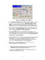
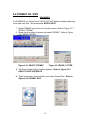
These directions describe how to configure the FOUND NEW HARDWARE
WIZARD for USB drivers.
4
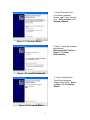
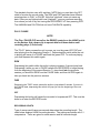
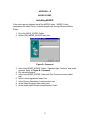
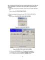
1. In the Welcome to the
Found New Hardware
Wizard, select “Yes, this time
only.” Refer to Figure 1.3.1
Hardware Wizard
Figure 1.3.1 Hardware Wizard
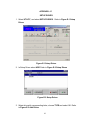
2. Select “ Install the software
automatically
(Recommended)” Refer to
Figure 1.3.2 Install
Automatically
Figure 1.3.2 Install Automatically
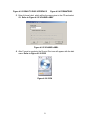
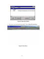
3. In the Completing the
Found New Hardware
Wizard select Finish. Refer
to Figure 1.3.3 Complete
Wizard
Figure 1.3.3 Complete Wizard
5
The computer recognizes the RECORDER if the same USB port is always
used and the Found New Hardware Wizard will not appear. Attaching the
recorder to a brand new USB port for the first time initiates the Found New
Hardware setup.
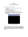
1.4 RED LED
A solid red LED (light) must always appear when RECORDER is connected to
the computer. The red LED appears only if the USB port supplies sufficient
power to the Recorder. If the power from the USB port is marginal an external
power supply such as USB hub should be used.
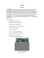
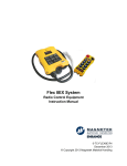
1.5 POWERED USB HUB
Most laptops and some desktops need the aid of an external power supply
(USB HUB) in order for the HAWK to function properly. If the power is
marginal the RECORDER will not connect or communicate with the
computer. The USB hub provided by ADS can be used to power the
RECORDER. The USB hub will be needed if the Red LED does not appear
from the recorder. All other USB devices such as PDAs, scanners, printers,
mouse, keyboard, etc, should be connected through the USB hub to reduce
device conflicts and power issues.
4 Port Powered USB HUB
Note!
Exiting this program should be done in a normal fashion. Killing power on
your computer in the middle of a program running under Windows may
cause you problems. If you are stuck, use CTRL-ESC-DELETE and
terminate the USBird program.
6
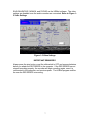
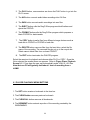
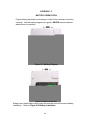
EAGLE8/A/B/C/D/E, MONO8, and FLEX8E use the USBird software. The video
settings are disabled once the audio recorders are connected. Refer to Figure 15 Video Settings
Figure 1-5 Video Settings
IMPORTANT REMINDER!!!
Always press the stop button or set the slide switch to OFF and remove batteries
before you attach the RECORDER to the computer. If the RECORDER has not
stopped recording properly, the recorder will begin recording again, once it is
reconnected to the computer, and receives power. The USBird program notifies
the user the RECORDER is recording.
7
SECTION 2
SETUP
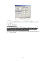
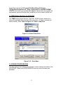
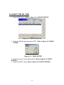
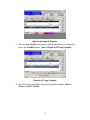
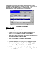
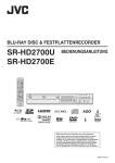
The SETUP menu shown in Figure 2-1 appears on startup. Always select
CONNECT RECORDER to read the settings of the attached RECORDER. The
top right half of the screen displays the Current Recorder Settings of the
RECORDER. Note the "Bad Chips" 0 of “X” for the HAWK, if you have any bad
memory chips in the RECORDER please call ADS and make arrangements to
have us repair the RECORDER at no cost to you. A RECORDER with some bad
chips is still usable, however the record time is reduced proportionately.
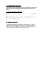
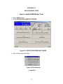
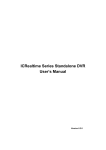
2.1 SETUP Settings - Descriptions and Functions
The RECORDER Clock is set to the same date/time as the PC; hence ensure
that the date/time on the PC is correct. The PC button configures the computer
time. The RECORDER button syncs the computer and recorder times. Refer
to Figure 2.1.1 Setup Menu. The Date/Time on the bottom of the screen is the
PC's, while the top of the screen displays the RECORDER Date/Time.
NOTE! The DATE format MM/DD/YYYY is set from the Windows CONTROL
PANEL. Hence if you want European format you can select it from "GLOBAL"
settings.
Figure 2.1.1 SETUP Menu
8
The APPROXIMATE RECORDING TIME: displays the amount of recording time
whether you have audio, video, or both. The RESOLUTION of the camera and
VIDEO RATE greatly effect the approximate recording time. The HIGH and
LOW Resolution are determined by which camera is currently connected. The
HAWK automatically recognizes the camera type that is connected hence
selecting “HIGH or LOW” is only for record time information.
The Video Rate sets the frames per second. The maximum is 30 f/s and the
minimum is1 f/s.
The AUDIO can set the recorder for stereo, left, right or no audio (video
recorders only). .
The COMPRESSION is used to manage the size and quality of the data. The
best audio is 1:1, the 2:1 (the default) is very good, while the 4:1 is good. The
video RECORDERS are set to 2:1.
The CAMERA VIEW displays the output from the HAWK / FALCON camera in
real time, it can be used to focus the camera and gives the operator an example
of what the camera will capture .
The DEFAULT, settings would be the most commonly used values for record
times. Typically this would be the ideal setting for most applications. The HAWK /
FALCON default is 15 f/s of video, 2:1 stereo audio, and standard “GAIN”.
The Record Time/ Quality, Setup, Bandwidth, and Gain can all be changed at
once. Select "APPLY CHANGES" once the desired settings are selected. Note
the changes on top of the screen after you select "APPLY CHANGES".
CURRENT RECORDER SETTINGS displays all the new settings of the recorder.
The TIMER MODE can be used to Start/Stop the RECORDER by its internal
clock when the local or remote RCD/OFF or ON/OFF (new recorders) are not
practical to use. Refer to Figure 2-2 for the Timer Entry Menu. You can only
setup the RECORDERS 1 week ahead of the current date/time.
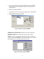
2.2 Set Timer:
1. In the SETUP Menu check the “ENABLED” box and select SET TIMER.
Refer to Figure 2.2.1 ENABLED/ SET TIMERS
9
Figure 2.2.1 ENABLED / SET TIMERS
2. At the TIMER RECORDING START DATE / TIME the TIME is in military
(24 Hour) format. Enter the date under TIMER RECORDING START
DATE. A calendar appears. Enter the time in the TIME section. The
TIME activates the recorder. Refer to Figure 2.2.2, Timer Mode Entry
3. Next enter the ”RECORD TIME,” the RECORD TIME keeps track of the
record length. Once RECORD TIME has completed the RECORDER
turns off. Refer to Figure 2.2.2, Timer Mode Entry
4. Set the IDLE TIME, it brings the RECORDER into hibernation mode.
Once hibernation time has completed the RECORDER will be reactivated.
If the RECORDER has no hibernation time, do not set IDLE TIME. Refer
to Figure 2.2.2, Timer Mode Entry
5. Select the RUN count, the number of times the RECORD TIME AND IDLE
TIME occur. (1= One Time) Selecting CONTINUOUSLY sets the
RECORDER to go through the RECORD TIME and IDLE TIME until
memory is full. Refer to Figure 2.2.2, Timer Mode Entry
6. Select “OK” to save settings and go back to the SETUP menu.
Refer to Figure 2.2.2, Timer Mode Entry
7. When you return to the SETUP menu don’t forget to “APPLY
CHANGES” thus the new settings are saved.
8. Note the “ TIMER MODE” indication on top right of the screen in
CURRENT RECORDER SETTINGS.
10
Figure 2.2.2 TIMER MODE Entry Menu
NOTE!! The unit automatically resets to MANUAL Mode after the data transfer. If
you uncheck the “ENABLE box” and choose “APPLY CHANGES”, the unit will
revert to Manual.
2.3 ERASE RECORDER
The RECORDER data memory MUST always be erased after each use. The
unit will not operate unless you have erased previous recordings, after
complete and proper data transfer off all recordings.
Depending on the unit, i.e., how much memory it has, the erasure may take from
1 to 16 minutes to finish.
11
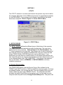
SECTION 3
UTILITY
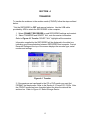
The UTILITY selection is covered next because the operator may need to define
the computer disk drives for the USBird program and run maintenance programs
for the RECORDER. If you received your computer from ADS the disk drives
have been configured. Refer to Figure 3-1 for the UTILITY Menu.
Figure 3-1 UTILITY Menu
3.1 SETUP DRIVES
The SETUP DRIVES defines the different types of disk drives of the computer.
The USBird does not automatically recognize the disk drive. The user has to
define the disk drives manually. Refer to Figure 3-3.2 The Drive Menu. The
"C" drive is assumed to be a hard disk. This program will not allow Formatting of
any hard disk. During new software installations the user has to enter the hard
drives, CD/DVD Writer, (CD\DVD Read only), and any MO drives . If you
partitioned your hard disk into multiple drives you can define those partitions as
well. If the disk drives are unknown, the disk drives and drive letters can be found
in the Windows Menu under "MY COMPUTER". Four drives is the maximum
that can be added. Refer to APPENDIX – F SETUP DRIVES for full drive
installation procedure.
3.2 Change Format Utility
The CD/DVD-WR (burner) uses the Roxio’s Drag to Disc software for the
FORMAT and EJECT functions. If ADS provided the computer system, the drives
are already installed. You can skip this part. If you are upgrading Roxio you will
need to define the path to the FORMAT UTILITY. The computers that ADS
provides, the path to DragToDisc is automatically set. If you provide your own
computer enter the path from the Change Format Utility button. The path to the
12
DragtoDisc software is C:\Program Files\Roxio\Easy CD Creator
7\DragtoDisc\DragtoDisc.exe. Refer to Appendix E-4 CHANGE FORMAT
UTILITY If the drive is a re-writable MO (Magneto Optical) then the program will
automatically use the Windows utility, therefore you do not need to define one.
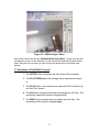
3.3 TEMP Button Sets Drive for AVI & WAV
The TEMP button selects the drive (hard disk, CD/DVD writer, thumb drive)
where AVI and WAV files are stored after conversion. A folder is created and
named HAWK_TEMP. Refer to Figure 3-3.1 Select Temp Drive
Figure 3.3.1 Select Temp Drive
Figure 3.3.2 Drive Menu
3.4 VIEW RECORDER REVISION
The data displays the hardware and software revision numbers and dates of the
RECORDER. Make sure all RECORDERS have the current firmware and
hardware.
13
3.5 CLOCK BATTERY EXPIRATION
The user may examine the internal Clock Battery expiration date from this menu.
Every two years ADS will change the battery and re-test the recorder at no
charge.
3.6 UPDATE RECORDER SOFTWARE
This button will load the firmware that is on the hard disk into the RECORDER.
This should be done as soon as possible when a new release is sent.
Reloading the firmware does not erase the recorded data and parameters.
Hence if you are having trouble with your unit, it is safe to reload your
firmware. Refer to Appendix-D.
3.7 MEMORY DIAGNOSTIC
The memory test should be run periodically, (about once every 90 days) to
identify failed chips. The recorder is still usable with a couple of bad chips
however, since ADS will repair any unit at no cost, it is recommended that the
recorder be sent back to ADS at your earliest convenience.
14
SECTION 4
TRANSFER
To transfer the evidence to the archive media (CD/DVD) follow the steps outlined
below:
* Set the RECORDER to OFF and remove batteries. Use the USB cable
provided by ADS to attach the RECORDER to the computer,
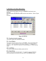
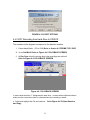
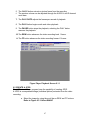
1. Select CONNECT RECORDER to read RECORDER settings and content.
2. Select TRANSFER and SELECT ALL, note the session information.
Refer to Figure 4-1 Transfer “SELECT ALL” highlights all the sessions.
Information supplied by the RECORDER will be displayed in the white box,
indicating good communication between RECORDER and computer. Current
Recorder Settings at the top of the screen displays the recorder type, serial
number and settings.
Figure 4-1 Transfer
3. If the sessions are transferred to the CD or DVD media you must first
FORMAT the blank media. Refer to the Section 4.2 Format CD / DVDs. After
the CD/DVD media has been formatted select the drive the data will be
archived on. Refer to Figure 4-2 Select Storage Device
15
Figure 4-2 Select Storage Device
After the user chooses DVD WR (DVD burner) or CD WR (CD burner) the
CD/DVD Select displays the type of media and which sessions will be
transferred.
Selecting DVD 1 transfers all the sessions that will fit on the first DVD. The size
of one DVD-R is 4.7 Giga bytes. DVD media has to be formatted. Refer to
Figure 4-3 DVD 1
Figure 4-3 “DVD 1”
A full HAWK/8 has 2 GBs of recording, transfers on multiple CD-Rs, typically 4. A
full HAWK4/8A, FALCON2/4 has 4 GBs of recording, transfers on multiple CDRs, typically 8.The data size of the HAWK recording determineS the number of
CD-Rs created. Figure 4-4 displays 4 CD-Rs are needed to transfer all the
HAWK data. The example shows selecting CD3 will transfer all the sessions that
16
will fit on the third CD. CD-R media has to be formatted first. Refer to Figure 4-4
CD3
FIGURE 4-4 “CD 3”
4. After the user views their selection in the CD/DVD Select, highlight DVD1 and
select TRANSFER.
Refer to Figure 4-6 TRANSFER BUTTON
FIGURE 4-6 TRANSFER BUTTON
The keyboard screen allows the user to input information regarding the data.
NOTE!
17
YOU SHOULD NOT USE SPECIAL CHARACTERS AND SPACES IN THE
FILE NAME.
5. Enter descriptive information and select Enter. Refer to Figure 4-7
Keyboard
6. Data transfer begins. When the blue bars stop, transfer is completed.
Refer to Figure
4-8 Transfer complete
Figure 4-7 Keyboard
The TRANSFERRING DONE displays when data transfer has completed. Select
the CLOSE from CD/DVD Select button to go back to the USBird. Refer to
Figure 4-8 Transfer Done
7. Playback the sessions through the PLAYBACK screen. Eject the CD/DVD.
Refer to Section 4.3 EJECT CD/DVD.
Figure 4-8 Transfer Done
18
4.1 Definitions of the Status Abbreviations
On the Transfer and Playback screens the STATUS of each session are
displayed.
Each abbreviation TR, FE, LB, and PF have their own definition. Refer to Figure
4-9
STATUS
Figure 4-9 STATUS
TR = Transferred session complete
The chosen session has transferred properly.
FE = Forced Ending
The session closed in order to fit on one CD MEDIA. One Forced Ending fills
one CD-R. You can select all of the sessions between 2 FE tagged files to
transfer to 1 CD. One DVD-R will hold 8 Forced Endings, or 2 HAWK memory
cards.
LB = Low Battery
The session stopped because battery power was low.
PF = Power Failure
Power to the recorder was interrupted. For example, removal of batteries
without pressing the stop button will cause a PF in the STATUS window.
19
4.2 FORMAT CD / DVD
WARNING!!!
For EVIDENCE you should use a “GOLD” CD/ DVD because cheap media may
loose data over time. We recommend “MITSUI GOLD”.
1. Select FORMAT button from the Transfer screen. Refer to Figure 4.2.1
SELECT FORMAT
2. Select the drive letter for burner and select FORMAT. Refer to Figure
4.2.2 DRIVE LETTER
Figure 4.2.1 SELECT FORMAT
Figure 4.2.2 DRIVE LETTER
3. The Roxio’s Drag to Disc interface appears. Refer to Figure 4.2.3
DRAG TO DISC INTERFACE
4. Right mouse click on the interface, and select Format Disc. Refer to
Figure 4.2.4 FORMAT DISC
20
Figure 4.2.3 DRAG TO DISC INTERFACE
Figure 4.2.4 FORMATDISC
5. Enter Volume Label, which will be the name given to the CD and select
OK. Refer to Figure 4.2.5 VOLUME LABEL
Figure 4.2.5 VOLUME LABEL
6. After Format is complete, the Drag to Disc icon will appear with the disk
name. Refer to Figure 4.2.6 ICON
Figure 4.2.6 ICON
21
4.3 EJECT THE CD / DVD
1. Select EJECT button. Refer to Figure 4.3.1 SELECT BUTTON
Figure 4.3.1 SELECT BUTTON
2. Select the DRIVE letter and select EJECT. Refer to Figure 4.3.2 DRIVE
LETTER
Figure 4.3.2
DRIVE LETTER
3. Check the boxes of all the three options. Refer to Figure 4.3.3 EJECT
OPTIONS
4. Select the EJECT button. Refer to Figure 4.3.3 EJECT OPTIONS
22
FIGURE 4.3.3 EJECT OPTIONS
4.4 COPY Recording from Hard Drive to CD/DVD
The numbers in the diagram correspond to the direction number.
1. Format blank Media. (CD or DVD) Refer to Section 4.2 FORMAT CD / DVD
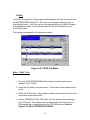
2. Go to PLAYBACK Refer to Figure 4.4.1 PLAYBACK SCREEN
3. At Play From select the storage device the recordings are archived.
Refer to Figure 4.4.1 PLAYBACK SCREEN
Figure 4.4.1 PLAYBACK SCREEN
In most cases the letter “C” designates the hard drive. In cases with multiple hard drives
make sure the correct drive letter is selected where the recording is stored.
4. Select and highlight the File and sessions.
and Copy
23
Refer Figure 4.4.2 Select Session
Multiple recordings can be transferred together, for example sessions numbered 4,5,and
6 can be copied together since they are in sequential order. IF you wanted to copy
sessions 1 and 6 you have to transfer them one at a time.
5. Select the COPY button Refer Figure 4.4.2 Select Session and Copy
Figure 4.4.2 Select Session and Copy
6.In the Select Destination Drive Screen choose the CD/DVD burner. Refer
Figure 4.4.3 Select Destination Drive
Figure 4.4.3 Select Destination Drive
7. Copy in Progress will be displayed at the bottom of the screen. Refer to
Figure 4.4.4 Copy in Progress
24
Figure 4.4.4 Copy in Progress
8. Once the Copy Complete is displayed, check to make sure the recording plays
back in the PLAYBACK Menu. Refer to Figure 4.4.5 Copy Complete
Figure 4.4.5 Copy Complete
9. Eject and Finalize the CD/DVD through the DragtoDisc program. Refer to
Section 4.3 EJECT CD/DVD
25
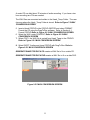
SECTION 5
PLAYBACK
In order to initiate playing video / audio perform the steps outlined below:
1. Select the PLAYBACK button located on the top row.
2. Select the “Source” drive, C, D, E etc in PLAY FROM
3. Select File and Session(s) you desire to listen and watch
4. Select Play button. Refer to Figure 5-1, Press PLAY
Figure 5-1 Press PLAY
Once you choose the file, it will be converted to MJPEG and played through the
USBirdPlayer. The recording will not be copied to the Hard disk, unless you
make an AVI file. Windows media Player will play the AVI file. Refer to Figure 52 “USBirdPlayer” Menu
26
Figure 5-2 “USBird Player” Menu
.
Most of the controls are obvious, Windows Media Player Menu. To play from any time,
just place the mouse on the “white box” on the time bar and hold the left mouse button
down. Drag the arrow to when you want to play and release the mouse button start
playing.
5.1 Definitions of PLAYBACK Controls
1. The SETUP button configures the disk drives of the computer.
2. The PLAY FROM selects the storage device sessions are stored
in.
3. The PLAY button, once sessions are chose the PLAY button to go
into the PLAY screen.
4. The AVI button converts audio/video recordings into AVI files. Our
proprietary video/audio format is stripped away.
5. The WAV button converts audio recordings into wav files. Our
proprietary audio format is stripped away.
27
6. The EJECT button calls the DragToDisc program which finalizes
and ejects the CD/DVD
7. The FORMAT button calls the DragToDisc program, which
prepares a blank CD/DVD for data transfer.
8. The COPY button transfer files from different storage devices such
as hard disk to CD/DVD or CD/DVD to hard disk.
9. The DELETE button removes files from the hard drive, select the
file name of the recording. The removed files do not go to the
recycle bin. Delete cannot delete files from a closed CD/DVD.
10. The ROTATE arrows will rotate the session video 90 degrees.
The ROTATE buttons are useful when the camera is upside down
or sideways.
1. Select the session.
2. Select the Rotate arrow until the session is right side up.
28
PLAY RATE can be
adjusted, for example if
a recording was
captured at 1 frame
per second you can
playback the recording
at 30 frames per
second for a faster
playback. Go to the
PLAY RATE meter
and move the bar.
Refer to Figure 5-4
PLAY RATE
Figure 5-4 PLAY RATE
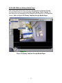
The PLAYBACK window can fit the entire screen by removing the PLAYER
graphical interface. This is used when the recording is made into an analog copy
such as VHS tape. Right click on the PLAYBACK screen and select FULL
SCREEN. Refer to Figure 5-5 FULL SCREEN
Figure 5-5 FULL SCREEN
29
Analog audio can be made from the USBird recording. First attach an audio tape
recording device to the sound card. Use the audio output of the sound card,
usually the green connector. At the PLAYBACK screen check the box labeled
ANALOG COPY. The Select screen appears. The select screen allows the
user to choose an audiotape length. After you choose the TAPE LENGTH the
audio will play. You should hit the record button on the audiotape device.
Refer to Figure 5-6 ANALOG COPY
Figure 5-6 ANALOG COPY
The AVI / WAV button converts the HAWK file to a standard AVI or WAV format
that can be played by any media player. The AVI button does not display the
video file once it has been converted. The AVI/WAV files are stored where the
HAWK_Temp folder is initialized in the UTILITY screen under SETUP DRIVES
and TEMP button. Refer to Figure 5-7 AVI/WAV Menu
Figure 5-7 AVI/WAV Menu
30
DATE AND TIME from Windows Media Player
The running time and the date of the AVI recording can be displayed through
Windows Media Player by selecting View, Now Playing, Tools, Caption. The
date and time of the recording will be displayed at the bottom left of the playback
screen. Refer to Figure 5-8 Display Captions through Media Player
Figure 5-8 Display Captions through Media Player
31
SECTION - 6
HAWK4/8/A / FALCON/4 EAGLE8/A RECORDERS
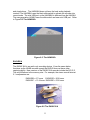
HAWK
The HAWK line of recorders can perform both video and or audio recording. The
record time is 30 f/s=1.7 HR; 15F/S=3 HR; 5 f/s-8 HR; 1 F/S=17 HR. The HAWK
memory expansion cards (up to a total of 8) can be added to the HAWK for
longer-term recordings. Each HAWK memory card adds 3 hours of lowresolution recording at 15 f/s.
The HAWK2 has 4 Gigabytes of memory while the HAWK4 has 8 Gigabytes.
The record time lengths double and quadruple depending on which recorder you
have. Refer to Figure 6-1 The HAWK.
The HAWK has remote and built in stereo microphone input, Manual or Timer
programmable “ON/OFF.” The HAWK has local audio playback controls.
Figure 6-1 The HAWK
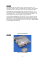
HAWK8/A
The HAWK8/A is the next generation audio / video recording device. The
HAWK8/A is a slimmer version of the HAWK/4 with more memory. The
advantages of the HAWK8 are you can move the recorder into objects where
size makes a difference. The HAWK memory is 4 Gigabytes, which gives you a
2 hour recording at 30 fps at high resolution The HAWK uses two or four triple A
alkaline or lithium batteries. The lithium battery will give you approximately 4
hours of battery life.
Another difference between the HAWK/4 and HAWK8/A is the removal of several
components from the HAWK/4 such as the audio connector and the red record
32
and stop buttons. The HAWK8/A does not have the local audio playback
controls. The HAWK8/A uses the black slide switch to activate the recorder into
record mode. The mini USB port on the HAWK8/A is different from the HAWK/4.
The new generation HAWK4 uses the slide switch and new mini USB port. Refer
to Figure 6-2 The HAWK8/A
Figure 6- 2 The HAWK8/A
EAGLE8/A
The EAGLE 8/A is an audio only recording device. It has the same button
functions as the HAWK recorder except the EAGLE does not have video
capturing ability. New versions of the EAGLE 8/A recorder include the B,C,D,E.
The only difference is the memory size. For example, the stereo record times at
2:1 compression are:
EAGLE8B = 6.7 hours EAGLE8D = 26.8 hours
EAGLE8C = 13.4 hours EAGLE8E = 53.6 hours
Figure 6-2 The
EAGLE 8/A
Figure 6-2 The EAGLE 8/A
33
FALCON/2
The FALCON is the next generation audio / video recording device. The
FALCON is a slimmer version of the HAWK with more memory. The advantages
of the FALCON are you can remove the recorder from the aluminum shell in
order to place the recorder in objects where size makes a difference. The
FALCON2/4 memory is 4 Gigabytes, which gives you a 4 hour recording at 30
fps at high resolution The FALCON uses a rechargeable lithium battery. The
lithium battery will give you approximately 4 hours of battery life.
Another difference between the HAWK and FALCON is the removal of several
components from the HAWK such as the audio connector and the record and
stop buttons. The FALCON uses the black slide switch to initiate the recording.
The mini USB port on the FALCON is different from the HAWK. Refer to Figure
6-3 for a picture of the FALCON
Figure 6-3 The FALCON
FALCON/4
Figure 6- The FALCON4
34
BATTERY Installation
The HAWK uses two 1.5 v, "AA" batteries for operation. The batteries are
installed series providing 3 volts. The HAWK8/A uses 2 and 4 “AAA” batteries.
Please note the label in the bottom of the unit for proper battery
installation.
Two "AA" Alkaline batteries will last for 3.5 – 4 hours, while two “AA” Photo
Lithium cells will last for 7.5 - 8 hours. You should not mix battery technology.
The HAWK uses about 315 mA at 3 volts while it is recording, and about 1 ma of
power while it is waiting, hence do not install the batteries a long time ahead of
its use. If the situation calls for it, you can insert the batteries a couple of days
ahead and still get the full recording.
NOTE!!
You should always use fresh batteries for each new operation. Used
batteries may leak, hence do not leave batteries in the RECORDERS.
LED
The RECORDERS have dual LEDs which turn red or green. The LED indicates
an operation. The RECORD "LED" in the front, near the RCD switch, is used the
same as the older FBIRD recorders. When the unit is turned "ON" the RECORD
LED will turn solid “red” indicating that it recognized the switch. When the
camera is connected, in 2 seconds the LED will turn solid “green” indicating that
the camera is ready and the record process has started.
Note!!
If the GREEN and RED LEDs do not show proper operation turn the HAWK
“OFF” for 5 seconds then press the “RCD” again.
Only during audio and no video recording the red LED will follow and trace the
loudest audio from the left microphone.
The LED will flash repeatedly 3 times when the recorder memory is full. If the
battery is low then the LED will flash ON and OFF slowly.
LED Codes
The red LEDs will flash 3 times repeatedly when the recorder’s memory is full.
Another reason for the red blinking LEDs is the data has been transferred and
the recorder memory needs to be erased. The recorder will not record. Go to
the nearest computer and erase the data.
35
If the battery is low then the LED will flash ON and OFF slowly.
No red or green LED present the record is not recording.
NOTE!
If the low battery indicator is flashing, turn the unit “OFF” replace the cells
and turn the unit ON or “RCD” again.
The computer will display the fact that the “last recording” was stopped short
because of a low battery condition.
The green "LED", further back, will be ON when the unit is in playback. In later
software releases the LED will follow the playback audio levels.
CAMERA
The HAWK has a variety of camera options. You can have a black and white or
color camera. The image sizes are (LOW resolution) 352 X 288 and (HIGH
resolution) 640 X 480 pixels. The VGA camera can operate both HIGH (640 X
480) and LOW (352 X 288) RESOLUTION MODE. The selection can be made
from “SETUP.”
The MICROCAM operates at 640 X 480. (High Resolution)
The HI-RES CAM operates at 1280 X 960 1.3 MEGAPIXEL
Dual Cameras have the advantage of two cameras, for applications that need
more than one camera angle.
Once the camera is connected and the unit is turned ON, the HAWK will
automatically detect and recognize which camera is used and adjusts the
parameters accordingly. Refer to Figure 6-2 HAWK with HAWKEYE (shirt
button), HCAM (pinhole) and the adjustable lens cameras.
NOTE!
If no camera is found the LED will not turn “GREEN”, hence you should turn the
unit “off” wait 5 seconds and try again. The HAWK will record “audio” if the
camera does not operate.
CAMERA DEFINITIONS
At the end of each camera connector there is a stripe that distinguishes the color
and type of the camera.
36
CAMERA
CIF
CIF
VGA
VGA
CAMERA RESOLUTION COLOR
LOW RESOLUTION
B/W
LOW RESOLUTION
COLOR
HIGH RESOLUTION
B/W
HIGH RESOLUTION
COLOR
STRIPES
NONE
RED
YELLOW
YELLOW/RED
MICROPHONE
The HAWK/EAGLE8 and FALCON can use its stereo internal or external
microphones. If the external microphone is plugged in it is automatically selected
for use. The Left and Right microphone position is engraved on the chassis. The
internal microphone is factory set for 6 dB more sensitivity, over the external
microphone.
USB PORT
The HAWK USB port uses a special USB cable that connects the HAWK to the
computer’s USB port. The HAWK communicates with the computer via USB.
HEADSET
The 1/8-inch stereo headset plug is used for playback. This output is intended for
use with headsets or powered speakers. The output is disabled during recording.
If at all possible this output should be used to playback the preamble.
CONTROL SWITCHES
The HAWK/EAGLE8 has the RCD/FWD and STOP/OFF momentary switches on
the side and the PLAY/PAUSE {P/P} as well as the REW, {R} on the bottom.
Refer to Figure 6-4 Hawk with button Descriptions or Figure 6-5 EAGLE8/A.
RECORDING
First Generation:
Our first generation recorders such as the HAWK/4 use the red push buttons that
are designated "RCD" and "STOP." Refer to Figure 6-4 Hawk with button
Descriptions or Figure 6-5 EAGLE8/A.
NOTE "PAUSE" is not active during recording
37
Next Generation:
Our next generation recorders such as the HAWK/4, HAWK8, FALCON/4 use a
black switch that slides into designated modes "ON" and "OFF
If the remote record switch is attached to the RECORDER it must be used for
ON/OFF control. When the red slide switch is slid to the “ON” position a black
dot appears and the recorder begins recording. For special applications, ADS
also makes a set of external microphones without the external ON/OFF switch.
NOTE!
To ensure proper operation,
depress all switches for about 2 seconds.
RCD/ON
The "RCD red button “or “ON black slide switch " activates the HAWK to go into
the record mode. The LED turns red, then green within 2 seconds to indicate
that the camera is attached. The LED will flash “red” following incoming audio
while the unit is recording.
NOTE!
The user should make a short “preamble” recording to check that
everything is attached and working properly. Make sure the red and green
LEDS are present, if they are not, go to the nearest computer and make
sure the memory has been erased and the batteries are new.
NOTE!
If you are in PLAY mode, you must turn the unit "OFF" before you can enter
the RECORD mode. During PLAY the RCD switch acts as the "FWD".
STOP/OFF
The "STOP red button " or “the OFF black switch” halts recording, and puts the
unit in a low power state. The RECORDER logs the states of ”ON / OFF” and the
date/time as “Session” information.
PLAYBACK
38
The playback function uses all 4 switches. NOTE that you must be in the OFF
state to re-enter the record mode. The REW and FWD switches have different
meaning when in PLAY or PAUSE. Note that “playback” does not erase any
data. Once you are finished with local “playback”, you may continue recording
from where you left off by first turning the RECORDER “off” then pressing RCD.
The HAWK8/A and FALCON4 do not have PLAYBACK capability.
PLAY / PAUSE
NOTE!
The Play / PAUSE (P/P) as well as the REW(R) controls on the HAWK unit is
on the bottom. Use a paper clip to operate and hold down button until
recording plays (3-5 seconds).
The "PLAY" button causes the unit to power up, turn the green LED 'ON" and
start playing from the beginning Session 1. Depressing this switch while the unit
is playing will cause it to PAUSE and flash the green LED. To continue playing
you must depress this switch again.
REW
Depressing this switch while the audio is playing causes a 3-minute jump back.
Depressing it while you are in PAUSE causes the RECORDER to begin playing
from the beginning of the current Session. To jump back into the previous
session you should hit REW from the PAUSE state, and then hit REW again to
take you back into the previous session.
FWD
Depressing the "FWD" switch causes the audio to jump ahead 3 minutes. If you are in
the PAUSE state, depressing this switch will jump you into the beginning of the next
Session.
OFF
Depressing this button will cause the recorded to be powered OFF. This must be
done to re-enter the RECORD mode.
RECORDING LENGTH
Type of camera and frames per second determines the recording length. The
chart below displays HAWK recording duration. The settings are stereo with 2:1
compression. Times are given for each session and full recorder length.
39
One Forced Session One Forced Session Full Recording Length
30 f/s
15 f/s
10 f/s
5 f/s
1 f/s
CIF (LOW)
22 minutes
42 minutes
60 minutes
105 minutes
258 minutes
VGA (HIGH)
14 minutes
27 minutes
40 minutes
73 minutes
212 minutes
CIF (LOW)
88 minutes
168 minutes
240 minutes
420 minutes
1032 minutes
VGA (HIGH)
56 minutes
108 minutes
160 minutes
292 minutes
848 minutes
RECORDING TIME AND BATTERY LIFE WITH VGA CAMERA
AND AUDIO ON
Battery
Duracell
Energizer
1 f/s
851 min
151 min
LB
5 f/s
293 min
138 min
LB
10 f/s
161 min
124 min
LB
15 f/s
111 min
Memory
Full
30 f/s
58 min
Memory
Full
458 min
LB
Memory
Full
Memory
Full
Memory
Full
Memory
Full
The EAGLE8/A has 420 minutes of recording time on 1 “AAA” battery and 18 hours on 2
“AAA” batteries.
TRANSMITTERS
Do not slide the XMT switch if antenna is not presently connected to the EAGLE/8
or HAWK recorder. Refer to Figure 6-6 Eagle8/Transmitter
In order to begin transmitting, press record button, then turn on the XMT switch. To
remove antenna, XMT switch should be in the off position first. XMT switch should
always be in the off position when not transmitting or in use.
40
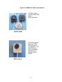
Figure 6-4 HAWK with button descriptions
The Micro Cams
records at 640X 480
pixels.
(High Resolution)
MICRO CAMS
The SXGA camera
records at 1290 x
960 resolution at
1.3 megapixel. The
SXGA is mainly
used in stationary
applications for
example, a pole
camera.
SXGA Camera
41
The Low Light
Cameras work well in
environment where
light is a limited
resource.
Low Light Cameras Long Lens, Button, Pinhole
Figure 6-5 EAGLE8/ A with
descriptions
Figure 6-6 EAGLE8/Transmitter
42
SECTION 7
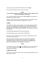
"MONO8" RECORDER
Figure 7-1 MONO8
The MONO8 audio recorder captures stereo for 10 hours or mono for 20 hours. Note
that the pager is fully functional with the exception of the vibrator function. The MONO8
has an Officer Safety Transmitter (OSRFT) option which transmits the audio
continuously for up to 6 + hours while recording with the “L91” Lithium battery. When the
MONO8 is not transmitting, an ordinary Alkaline “AA” will last for 10+ hours. The
MONO8 uses the USB port of the PC for data archive making it a very transportable unit.
Refer to Figure 7-1 MONO8
The MONO8A is the latest model it has more memory and records 13 stereo hours.
BATTERY
NOTE, a battery should be left in the unit while on the shelf to keep the pager
function settings. This should not be confused with the recorder settings, which are
kept even without a battery. A fresh battery must be installed on every new recording.
DOWNLOAD CABLE / GUIDE PIN
The Download / Control cable plugs in just to the inside of the coil spring. The "key"
Guide Pin is towards the outside (short) end. Please be gentle, and insert and pull the
cable straight out.
RCD
The "ON" and "OFF" switches are momentary, and should be held for about 1/2 second.
Note the red LED will follow the audio. NOTE, please do not exert excessive force
when depressing the switch.
43
SECTION 8
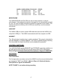
FLEX8F
The FLEX8F is our most covert recorder. The solid-state electronics built on an
untra-thin form factor assures inconspicuous evidence recording in highly
transportable packages. Data is transferred to any PC via a Universal Serial Bus
(USB). Standard audio hardware commonly found on most PCs may be used for
data playback. User software running under Windows 98/2000/XP/VISTA® will
cut CD media for archive, and can also create audio CDs which can be played on
any CD player. Due to more dense memory boards we are able to create
recorders with longer record times such as the FLEX8C2/ D / E. Refer to Figure
8-1 FLEX8F
System features:
•
Local Record START/STOP
•
Playback via Standard Audio Cards
•
Programmable Timer ON/OFF
•
13.4 Hrs Stereo / 26.8 Hrs Mono Record
•
Local Microphone Inputs
•
Interface to USB Port
•
1:1, 2:1, 4:1 record compression
•
Optional "Officer Safety" Transmitter
•
Measures 1.75" x 0.9" x 0.18"
•
Uses flat rechargeable Lithium cells
Figure H-1 FLEX8F
44
SECTION 9
PLAYER Program
The “PLAYER” is similar to our FBPLAYER used on the earlier EAGLE 2 and 4
line. The PLAYER plays audio and video files from the recorders however the
PLAYER cannot change the settings of the RECORDER. The PLAYER code
resides on all evidence CDs inside the HAWK directory. The PLAYER can
execute on any PC and uses the PC’s Sound Blaster for audio output. To run
PLAYER simply double click on the ICON located on the CD/DVD under
HAWK/Player.exe . If you are using USBIrd software 2.6x and lower versions be
sure to install the MJPEG codec. The MJPEG codec is located in the CODEC
folder in the evidence CD. The main menu is shown in Figure 9.1.
Figure 9. 1 PLAYER Main Menu
The user can select which drive to play back from. Once the drive is selected the
file names appear on the screen, as shown above. After you select a file the
Sessions information appears on the screen.
PLAYER BUTTON DESCRIPTIONS
1. The SETUP button configures the disk drives of the computer.
2. The PLAY FROM selects the storage device sessions are stored in.
45
2. The PLAY button, once sessions are chose the PLAY button to go into the
PLAY screen.
3. The AVI button converts audio/video recordings into AVI files.
4. The WAV button converts audio recordings into wav files
5. The EJECT button calls the DragToDisc program which finalizes and
ejects the CD\DVD.
6. The FORMAT button calls the DragToDisc program which prepares a
blank CD/DVD for data transfer
.
7. The COPY button transfer files from different storage devices such as
hard disk to CD/DVD or CD/DVD to hard disk.
8. The DELETE button removes files from the hard drive, select the file
name of the recording. The removed files do not go to the recycle bin.
Delete cannot delete files from a closed CD/DVD
9. The EXIT button terminates the PLAYER program.
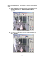
Select the sessions for playback and choose either PLAY or COPY. Once the
file is selected the screen shown on appears. Refer to Figure Player Playback
Screen 9.1.1 From here the user can automatically make .WAV or .AVI files.
Note that one CD will typically hold about 1 hour of recording from a
HAWK.
9.1 PLAYER PLAYBACK MENU BUTTONS
1. The SET button creates a bookmark in the time bar.
2. The CLEAR button removes previous bookmark.
3. The CLEAR ALL button removes all bookmarks.
4. The SEGMENT button extracts a portion of the recording created by the
BOOKMARKS.
46
5. The IMAGE button extracts a picture frame from the recording
6. The session volume can be adjusted through the AUDIO L and R channel
scroll bars.
7. The PLAY RATE adjusts the frames per second of playback.
8. The PLAY button begins audio and video playback.
9. The PAUSE button stops the playback, selecting the PLAY button
resumes the playback.
10. The REW button advances the video recording back 1 frame.
11. The FF button advances the video recording forward 1 frame.
Figure Player Playback Screen 9.1.1
9.2 CREATE A JPEG
The USBird and Player program have the capability of creating JPEG.
A JPEG is a compressed image (individual picture) extracted from the video
recording.
a. Select the image by using the scroll bar or REW and FF buttons.
Refer to Figure 9.2.1 Select IMAGE
47
Figure 9.2.1 Select IMAGE
b. Next select the PAUSE button. Refer to Figure 9.2.1 Select
IMAGE
c. Select the IMAGE button. Refer to Figure 9.2.2 IMAGE Button
Figure 9.2.2 IMAGE Button
48
d. In the SAVE AS screen select the location where to save the JPEG
(use the down arrow to navigate through the folders) and input a
name for the JPEG in the File name. Refer to Figure 9.2. 3 Save
As Screen
e. Select Save. Refer to Figure 9.2. 3 Save As Screen
Figure 9.2. 3 Save As Screen
f. Retrieve the JPEG for viewing. Refer to Figure 9.2.4 JPEG
Figure 9.2.4 JPEG
9.3 CREATE A SEGMENT
The USBird and Player program have the capability of creating SEGMENTS.
The user can select a portion from the recording. For example, you may have
four hours of recording, in that recording you may only need 2 minutes. The
extracted portion of the recording is a segment. The segment is separated
49
into its own individual session. The SEGMENT is created in the PLAYBACK
screen.
1. Create the segment by using the scroll bar. Find the beginning of the
SEGMENT and select SET. Refer to Figure 9.3.1 Start of
SEGMENT
Figure 9.3.1 Start of SEGMENT
2. Find the end of the SEGMENT select SET. Refer to Figure 9.3.2
End of SEGMENT
50
Figure 9.3.2 End of SEGMENT
3. Select the SEGMENT button. Refer to Figure 9.3.3 SEGMENT
Button
Figure 9.3.3 SEGMENT Button
10. In the CaseIDForm screen the SEGMENT is designated by the SG
followed by the original file name and session number. The FILE NAME
can be renamed. Refer to Figure 9.3.4 CaseIDForm
11. Select OK. Refer to Figure 9.3.4 CaseIDForm
Figure 9.3.4 CaseIDForm
The CLEAR button removes the previous bookmark from the scroll bar.
The CLEAR ALL button removes all the bookmarks from the scroll bar
9.4 AVI
An AVI file created for other programs that recognize AVI file format such as
WINDOWS MEDIA PLAYER. We covert our proprietary audio/video format to a
51
common user friendly format. An AVI file can be converted to the MJPEG2
format which can be played back on a standard DVD player. AVIs can also be
generated from the USBird Program in the Playback screen. In this
demonstration the AVI will be made from the PLAYER program.
Figure 9.4.1 AVI File Menu
Make “ .AVI” Files
The numbers corresponds to the direction number.
1. From the PLAYER PROGRAM, Select the drive where sessions are
stored in PLAY FROM. Refer to Figure 9.4.1 AVI FILE Menu
2. Select the File name, and one session. AVIs can only be created one at a
time. Refer to Figure 9.4.1 AVI FILE Menu
3. Select AVI button. Refer to Figure 9.4.1 AVI FILE Menu
4. Choose the GENERATE AVI FOR DATA DVD. This selection will slice
the recording in order to fit on DVDs. The number of DVD’s needed
depends on the length of the recording and displayed in the CD/DVDs
column. Refer to Figure 9.4.2 AVI Conversion SCREEN
The AVI files are converted and written to a Hawk_Temp Folder. The user
chooses where the Hawk_Temp Folder is stored. Refer to Figure 9.4.2 AVI
Conversion SCREEN
52
5. Insert a blank CD\DVD in the CD\DVD-WRITER and select FORMAT.
Format the CD using the DragToDisc software. Refer to Section 4.1
Format CD/DVD
6. Select the AVI under CONTENT
7. Select COPY, the AVI file is copied from Hawk_Temp to the CD/DVD.
8. Select EJECT and close out the CD
Figure 9.4.2 AVI Conversion SCREEN
GENERATE AVI FOR DATA DVD creates AVIs stored on DVD media.
GENERATE SILENT AVI will create a file with video and no audio.
A WAV file can be created from an audio/video recording. From the AVI
Conversion Screen select WAVE. Follow the WAV instructions. The video
will be stripped from the recording leaving only the audio.
Figure 9.4.2 AVI Conversion SCREEN
53
9.5 WAV
A WAV file is created for other programs that recognize the WAV file format such
as WINDOWS MEDIA PLAYER. We covert our proprietary audio format to a
user-friendly format. WAV files can also be generated from the USBird Program
in the Playback screen. In this demonstration the AVI will be made from the
PLAYER program.
The numbers corresponds to the direction number.
Figure 9.5.1 WAV File Menu
Make “ .WAV” Files
1. From the PLAYER PROGRAM, Select the drive where sessions are
stored in PLAY FROM.
2. Select the File name, and one session. WAVs can only be created one at
a time.
3. Select the WAV button. If the session contains video select AVI and in the
conversion screen select WAV.
4. Choose GENERATE WAV FOR Audio CD, this will slice the recording to
fit on CD media. The length of the recording determines the number of
CDs needed and is displayed under the CD/ DVDs column. Refer to
Figure 9.5.2 WAV CONVERSION SCREEN
54
A music CD can hold about 70 minutes of audio recording. If you have a two
hour recording two CDs are needed.
The WAV files are converted and written to the Hawk_Temp Folder. The user
chooses where the Hawk_Temp Folder is stored. Refer to Figure 7-5 WAV
CONVERSION SCREEN
5. Insert a blank CD\DVD in the CD\DVD-WRITER and select FORMAT.
Format the CD using the DragToDisc software. Refer to Section 4.1
Format CD/DVD Refer to Figure 9.5.2 WAV CONVERSION SCREEN
6. Select the WAV under CONTENT, Refer to Figure 9.5.2 WAV
CONVERSION SCREEN
7. Select COPY, the WAV file is copied from Hawk_Temp to the CD/DVD.
Refer to Figure 9.5.2 WAV CONVERSION SCREEN
8. Select EJECT, finalize and close CD/DVD with DragToDisc. Refer to
Figure 9.5.2 WAV CONVERSION SCREEN
GENERATE WAVE FOR DATA CD creates a WAV file to fit on a data CD.
.
GENERATE WAVE FOR DATA DVD creates a WAV file to fit on a data DVD.
Figure 9.5.2 WAV CONVERSION SCREEN
55
APPENDIX - A
USBird SOFTWARE INSTALLATION
To install/update the resident code from CD.
1. Remove existing software from the CONTROL PANEL/ ADD REMOVE
PROGRAMS
.2. Go to USBird folder and select ‘Setup.exe’.
10. In the Welcome screen, select next.
11. In the Choose destination location, select next.
12. In the Select Program Folder, select next. Start Copying files begins.
13. Drag out USBird short cut to Desktop.
14. Check the box, “Yes, Launch the program first” and select next in the
Setup Complete screen. Refer to Figure A-1 Setup Complete
15. Close Hawk folder.
Figure A-1 Setup Complete
After the installation, if you do not have a shortcut icon for the USBird, you
can go into Windows Explorer and open C:\PROGRAM FILES\ADS\USBird.
From there you can drag the shortcuts “blue torch icons” {USBird.EXE} out
by pointing to it and holding down the left mouse button as you drag it off
the screen.
56
APPENDIX – B
MJPEG CODEC
Installing MJPEG
If the video can not playback install the MJPEG codec. MJPEG Codec
compresses the Hawk File so it can be played back through Windows Media
Player.
1. Go to the MJPG_CODEC Folder.
2. Select LEAD MCMP_MJPEGCodec.exe.
Figure B - Password
3. In the Lead MCMP_MJPEG Codec – Password type “showme” and select
continue. Refer to Figure B - Password
4. File extraction begins.
5. In the Lead MCMP_MJPEG Codec with Free Converter screen select
next.
6. In the License Agreement select Yes.
7. In the Choose Destination Location select next.
8. At the Select Program folder select next.
9. At the Install shield Wizard complete select Finish.
57
APPENDIX - C
WINDOWS MEDIA PLAYER
Installing Windows Media Player 7.1
If your computer does not correctly display AVI files install new Windows
Media Player 7.1.
1.
2.
3.
4.
5.
6.
7.
8.
Go to My Computer and go to USBIRD CD.
Select mp71.exe
In the Windows Media Player 7.1 Setup select Yes.
In the License agreement, select Yes and file extraction begins.
In the Windows Media Component Setup select next.
Check the box, ‘I have read the Privacy Statement’ select next.
In the Components screen make sure all boxes are checked select next.
In the Customize your Windows Media Player all boxes are checked
select next.
9. In Windows Media Setup is ready to install select next.
10. In Setup has completed select Finish.
58
APPENDIX - D
UPDATE BINARY CODE
How to update HAWK Binary Code
1. Select Utility button.
2. Select UPDATE RECORDER SOFTWARE.
Figure D-1 UPDATE RECORDER SOFTWARE
3. In the Confirm box select Yes.
Figure D-2 Confirm box
Important!
59
Do not unplug the recorder while it is updating the binary code, this can
cause malfunction in the Hawk. Code update takes approximately 40
seconds.
4. After binary code update is complete, select OK at the CODE UPDATED
box.
Refer to figure D-3 CODE UPDATED BOX.
5. Binary code update is successful when “HEX CODE LOAD DONE” is
displayed.
Refer to figure D-4 HEX CODE LOAD DONE SCREEN
Figure D-3 CODE UPDATED BOX
Figure D-4 HEX CODE LOAD DONE SCREEN
6. Disconnect RECORDER from USB cable for 10 seconds.
7. Reconnect RECORDER and select CONNECT RECORDER
8. Go to Setup and select the APPLY CHANGES button.
60
APPENDIX – E
SETUP DRIVES
1. Select UTILITY, and select SETUP DRIVES. Refer to Figure E-1 Setup
Drives
Figure E-1 Setup Drives
2. In Setup Drives select ADD Refer to Figure E-2 Setup Drives
Figure E-2 Setup Drives
3. Select drive with corresponding letter, choose TYPE and select OK. Refer
to Figure E-3 Add Drives
61
Figure E-3 Add Drives
4. If the space is blank, press Change Format Utility button, to select the
format program. The path for ROXIO 5 is C:\Program Files\Adaptec\Easy
CD Creator\DirectCD\directcd.exe. The path for ROXIO 6 is C:\Program
Files\Roxio\Easy CD Creator 6\DragtoDisc\DragtoDisc.exe. Refer to
Figure E-4 CHANGE FORMAT UTILITY
Figure E-4 CHANGE FORMAT UTILITY
5. The new drive will be added, select OK. Refer to Figure E-5 New Drive
Added
62
Figure E-5 New Drive Added
6. Now you can view the drives that were added. Refer to Figure E-6 View Drives
Figure E-6 View Drives
63
APPENDIX - F
BATTERY ORIENTATION
Proper battery placement is necessary in order for the recorder to function
correctly. Use the battery diagram as a guide. NEVER remove batteries
when device is recording.
Figure G-1 Battery Diagram
Figure G-2 Battery Installation
Always use a fresh battery when using the recorder and follow correct battery
installation. Refer to Figure G-2 Battery Installation
64
APPENDIX - G
ADS SOFTWARE CONFIGURATIONS
This message was written to clear up some confusion that may exists on the
various software and hardware releases that are out in the field.
FBIRDWIN 3.5 (and 3.X) is used with desktops and PDR (not PDR2)
stations. This software will not run on Windows 2000, and Windows XP.
USBI 1.91 (and 1.0x) is used with the black USB boxes as well as the PCI
card version. When the little black box is used
Both the FBIRDWIN and USBI software handles the following recorders:
EAGLE2/A,
EAGLE4/A/C
FBIRD8/A/B
MONO2/A
MONO4
FLEX8B
“USBird” 3.05 (3.XY) is used on all new recorders that have a built in USB port
and attached wris transceiver. In fact, everything to be released from now on will
use this software. The recorders already using the USBird 3.05 software are:
HAWK/4 /8 /8A
FALCON/4
EAGLE8/A /A2 /A3 / B / B2 /C /C1 /D /E
MONO8/ A
FLEX8C /C2 /D /E /F
NOTE!! Much like the “FBPLAYER” is burned onto the evidence “CD”, a program
called “USBirdPLAYER” will be burned onto the CD / DVD using the USBird 2.00
and later releases. The “USBirdPLAYER” can be called up from the evidence CD
/ DVD and the video/ audio be player without any additional software from ADS.
The USBirdPLAYER software can also be used to make “.AVI” copies which can
be burned onto CD / DVD.
65
APPENDIX - H
TROUBLE SHOOTING
Most problems can be solved by referring to the USBIRD MANUAL.
Before you use the recorder, make sure memory has been erased. If you press
the record button and see three blinking lights you must erase the recorder
memory. The memory cannot not be overwritten, after you completely erase the
memory the recorder will begin recording.
Always test the recorder before you deploy it. Make sure audio and video are
working properly. Always use fresh batteries, and give rechargeable batteries
enough time to recharge.
All external cables and connectors are fastened securely and all cameras are in
focus.
All external microphones are in a good audio position to capture audio.
The external on / off switch should be on the off position when you are attaching
the switch to the recorder.
No other USB devices can be attached to the computer while you are using a
recorder. If you need to attach another USB device such as a USB printer,
scanner, mouse, use a USB HUB. The USB HUB should be the only device
attached to the computer and all devices should be plugged into the USB HUB.
VIDEO DOES NOT PLAYBACK for USBird installations 2.6x and older. Install
MJPEG codec.
66
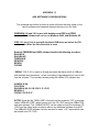
APPENDIX – I
Micro Cam Installation
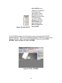
Mounting a MICROCAM into the concealment is made easy by the items below. The
three items are shipped with the MICROCAMS. The items include, a drill bit, a center
punch, and camera bezel or frame.
MICROCAM Concealment Kit
1. Choose an item
2. Make sure the surface lays flat
and does not distort while
moving.
3. Place the center punch and
camera bezel flat on the item.
4. Mark the edges of the camera
bezel for easy alignment.
67
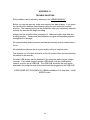
Center Punch and Camera Bezel
Drill Bit
5. Place the drill bit inside the center punch. The center punch and camera
bezel align the camera hole.
6. Once the camera hole is made remove the drill bit and center punch.
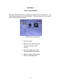
7. Replace the center punch with the MICROCAM.
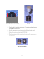
8. Glue down and around the camera bezel; make sure the camera lens is
not obstructed.
MICROCAM in BEZEL
68