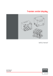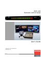
1
RCP-120
Remote Control Panel
User’s Guide
• Manual #: 26-1004000-00
• Revision: 00
Remote Control Panel ● User’s Guide
Copyright
© Barco. March 9, 2011
All rights reserved. No part of this document may be copied, reproduced or translated. It
shall not otherwise be recorded, transmitted or stored in a retrieval system without the prior
written consent of Barco.
Notice
Barco provides this manual “as is” without warranty of any kind, either expressed or
implied, including but not limited to the implied warranties or merchantability and fitness for
a particular purpose. Barco may make improvements and/or changes to the product(s) and/
or the program(s) described in this publication at any time without notice.
This publication could contain technical inaccuracies or typographical errors. Changes are
periodically made to the information in this publication; these changes are incorporated in
new editions of this publication.
Federal Communications Commission (FCC) Statement
This equipment has been tested and found to comply with the limits for a class A digital
device, pursuant to Part 15 of the FCC rules. These limits are designed to provide
reasonable protection against harmful interference when the equipment is operated in a
commercial environment. This equipment generates, uses, and can radiate radio frequency
energy and, if not installed and used in accordance with the instruction manual, may cause
harmful interference to radio communications. Operation of this equipment in a residential
area may cause harmful interference, in which case the user will be responsible for
correcting any interference.
Guarantee and Compensation
Barco provides a guarantee relating to perfect manufacturing as part of the legally
stipulated terms of guarantee. On receipt, the purchaser must immediately inspect all
delivered goods for damage incurred during transport, as well as for material and
manufacturing faults Barco must be informed immediately in writing of any complaints.
The period of guarantee begins on the date of transfer of risks, in the case of special
systems and software on the date of commissioning, at latest 30 days after the transfer of
risks. In the event of justified notice of compliant, Barco can repair the fault or provide a
replacement at its own discretion within an appropriate period. If this measure proves to be
impossible or unsuccessful, the purchaser can demand a reduction in the purchase price or
cancellation of the contract. All other claims, in particular those relating to compensation for
direct or indirect damage, and also damage attributed to the operation of software as well
as to other services provided by Barco, being a component of the system or independent
service, will be deemed invalid provided the damage is not proven to be attributed to the
absence of properties guaranteed in writing or due to the intent or gross negligence on the
part of Barco.
If the purchaser or a third party carries out modifications or repairs on goods delivered by
Barco, or if the goods are handled incorrectly, in particular if the systems are commissioned
operated incorrectly or if, after the transfer of risks, the goods are subject to influences not
agreed upon in the contract, all guarantee claims of the purchaser will be rendered invalid.
2
Remote Control Panel User’s Guide ● Rev 00
Not included in the guarantee coverage are system failures which are attributed to
programs or special electronic circuitry provided by the purchaser, e.g. interfaces. Normal
wear as well as normal maintenance are not subject to the guarantee provided by Barco
either.
The environmental conditions as well as the servicing and maintenance regulations
specified in this manual must be complied with by the customer.
Trademarks
Brand and product names mentioned in this manual may be trademarks, registered
trademarks or copyrights of their respective holders. All brand and product names
mentioned in this manual serve as comments or examples and are not to be understood as
advertising for the products or their manufactures.
Company Address
Barco, Inc.
11101 Trade Center Drive
Rancho Cordova, California 95670
USA
• Phone: (916) 859-2500
• Fax: (916) 859-2515
• Website: www.barco.com
Barco N.V.
Noordlaan 5
8520 Kuurne
BELGIUM
• Phone: +32 56.36.82.11
• Fax: +32 56.35.16.51
Technical Support
• Customer Service Portal — www.barco.com/esupport
• (866) 374-7878 — Events (24/7)
• (866) 469-8036 — Digital Cinema (24/7)
Remote Control Panel User’s Guide ● Rev 00
3
Operators Safety Summary
The general safety information in this summary is for operating personnel.
Do Not Remove Covers or Panels
There are no user-serviceable parts within the unit. Removal of the top cover will expose
dangerous voltages. To avoid personal injury, do not remove the top cover. Do not operate
the unit without the cover installed.
Power Source
This product is intended to operate from a power source that will not apply more than 230
volts rms between the supply conductors or between both supply conductor and ground. A
protective ground connection by way of grounding conductor in the power cord is essential
for safe operation.
Grounding the Product
This product is grounded through the grounding conductor of the power cord. To avoid
electrical shock, plug the power cord into a properly wired receptacle before connecting to
the product input or output terminals. A protective-ground connection by way of the
grounding conductor in the power cord is essential for safe operation.
Use the Proper Power Cord
Use only the power cord and connector specified for your product. Use only a power cord
that is in good condition. Refer cord and connector changes to qualified service personnel.
Do Not Operate in Explosive Atmospheres
To avoid explosion, do not operate this product in an explosive atmosphere.
4
Remote Control Panel User’s Guide ● Rev 00
Terms In This Manual and Equipment Marking
WARNING
Highlights an operating procedure, practice, condition, statement, etc.,
which, if not strictly observed, could result in injury to or death of personnel.
Note
Highlights an essential operation procedure, condition or
statement.
CAUTION
The exclamation point within an equilateral triangle is intended to alert the
user to the presence of important operating and maintenance (servicing)
instructions in the literature accompanying the appliance.
AVERTISSMENT!
Le point d´exclamation dans un triangle equilatéral signale à alerter
l´utilisateur qu´il y a des instructions d´operation et d´entretien tres
importantes dans la litérature qui accompagne l´appareil.
VORSICHT
Ein Ausrufungszeichen innerhalb eines gleichwinkeligen Dreiecks dient dazu,
den Benutzer auf wichtige Bedienungs-und Wartungsanweisungen in der
Dem Great beiliegenden Literatur aufmerksam zu machen.
Remote Control Panel User’s Guide ● Rev 00
5
Change History
The table below lists the changes to the Remote Control Panel User’s Guide.
Rev
Date
ECP #
00
3/09/11
586290
6
Description
Initial Release
Approved By
R. Pellicano
Remote Control Panel User’s Guide ● Rev 00
Table of Contents
Introduction.....................................................................10
Overview........................................................................................................... 10
Connectivity Diagram .......................................................................................... 11
Application Questions .......................................................................................... 11
1. Remote Control Panel Orientation ...............................12
RCP-120 Front Panel ........................................................................................... 12
RCP-120 Rear Panel ............................................................................................ 12
2. Installation ..................................................................14
Unpacking and Inspection .................................................................................... 14
What’s Included in the Box................................................................................... 14
RCP-120 Installation ........................................................................................... 15
3. RCP-120 Configuration ................................................16
Soft Reboot / Web Interface Password Reset ..........................................................
Connecting to the RCP-120 Web Interface ..............................................................
RCP-120 Configuration Web Interface ....................................................................
Status ...........................................................................................................
Network Configuration .....................................................................................
Change Admin Password ..................................................................................
Serial Port 1 Configuration / Baud Rate...............................................................
Serial Port 2 Configuration / Baud Rate...............................................................
Serial Port 1 Auto Transmit ...............................................................................
Button Settings ...............................................................................................
Update and Reboot / Reset Defaults ...................................................................
RCP-120 Boot Menu ............................................................................................
Overview .......................................................................................................
Connecting to the Boot Menu ............................................................................
RCP-120 Boot Menu Interface...............................................................................
Display Current Settings...................................................................................
Configure IP Settings .......................................................................................
Set Password ..................................................................................................
Set Host Name................................................................................................
Set Master Controller IP Address .......................................................................
Restore Default Settings...................................................................................
Discard Changes and Reboot.............................................................................
Save Changes and Reboot ................................................................................
Selections Not Supported .................................................................................
16
16
19
19
19
20
21
21
21
22
22
23
23
23
24
24
24
24
24
24
25
25
25
25
4. RCP-120 FSN Menu Orientation ...................................26
Assign Remote Panels ......................................................................................... 26
Remote Control Panel Table .............................................................................. 27
Remote Control Panel User’s Guide ● Rev 00
7
Assign Remote Panels Menu Functions................................................................ 28
Duplicate IP Address Notification ....................................................................... 30
5. Operations ...................................................................31
No Connection Behavior.......................................................................................
Display IP/MAC Address and Firmware Version........................................................
AUX Output Control ............................................................................................
Understanding Button Mapping..........................................................................
Understanding Button Color ..............................................................................
Working with the RCP-120 ................................................................................
Setting up the RCP-120 to Control an Aux Output ................................................
Maintenance Operations ...................................................................................
Controlling an Aux Output with the RCP-120 .......................................................
31
31
32
32
33
34
36
37
38
7. Updating Software .......................................................40
Software Update Overview ...................................................................................
Hardware Requirements ......................................................................................
Downloading Software.........................................................................................
Via FTP Site ....................................................................................................
Via Web Site...................................................................................................
Updating RCP-120 Software .................................................................................
40
40
41
41
42
43
A. Specifications ..............................................................45
Physical and Electrical Specifications......................................................................
Communications Specifications .............................................................................
Agency Specifications ..........................................................................................
Pinouts..............................................................................................................
Power Connector .............................................................................................
Serial Port ......................................................................................................
LAN ...............................................................................................................
45
46
46
46
46
47
47
B. Universal Power Supply ..............................................48
Overview........................................................................................................... 48
Installing a Power Blade Adapter........................................................................... 48
C. Contact Information....................................................50
Warranty ........................................................................................................... 50
Return Material Authorization (RMA)...................................................................... 50
Contact Information ............................................................................................ 51
8
Remote Control Panel User’s Guide ● Rev 00
This page intentionally left blank.
Remote Control Panel User’s Guide ● Rev 00
9
Introduction
Overview
The Remote Control Panel integrates auxiliary FSN System function control into a
convenient 12 button 1RU panel. General features include:
•
•
•
•
•
12 buttons with integrated graphical displays for electronic labeling
Ethernet connectivity to the FSN Network
19” Rack mountable
Support for up to 32 panels per FSN System
Integrated web interface for quick panel setup and configuration
Please note:
To ensure trouble-free operation between the FSN System and the Remote Control Panel,
refer to the FSN Series User’s Guide (26-0702000-00 Rev 01 or later) and the current
“Whatsnew_FSN Series Switcher” included with the FSN Controller software bundle for all
procedures relating to general FSN System setup and concept definitions. Only concepts and
procedures relating to using the RCP-120 with the FSN System will be covered in this
manual.
10
Remote Control Panel User’s Guide ● Rev 00
Connectivity Diagram
The figure below illustrates a basic FSN Series system, showing a typical usage of the
Remote Control Panel to switch inputs for FSN AUX outputs.
AUX Output
AUX Output
EIC Monitor
N1- 1
--- --- N2- 1
N1- 2
---- --N2 - 2
N1- 3
-- --- -N2- 3
N1- 4
--- ---N2- 4
N1- 5
- --- --N2- 5
N1- 6
-- --- -SB- 1
N1- 7
--- ---SB- 2
N1- 8
- --- --SB- 3
U1- 1
-- ---- 7 5CB
U1- 2
---- --SMPTE
SHI FT
AUTO
TRANS
RMT-120
Remote Control Panel
Record
Station
Ethernet
N1- 1
--- --- N2- 1
N1- 2
---- --N2 - 2
N1- 3
-- --- -N2- 3
N1- 4
--- ---N2- 4
N1- 5
- --- --N2- 5
N1- 6
-- --- -SB- 1
N1- 7
--- ---SB- 2
N1- 8
- --- --SB- 3
U1- 1
-- ---- 7 5CB
U1- 2
---- --SMPTE
SHI FT
AUTO
TRANS
RMT-120
Remote Control Panel
Figure 1-1: FSN System Connectivity Diagram
Application Questions
At Barco, we take pride in offering unique solutions to demanding technical problems. If
you have application questions, require further information or would like to discuss your
application requirements in more detail, please call (866) 469-8036. Our Customer
Support Engineers will be happy to supply you with the support you need. Refer to
Appendix C, “Contact Information” at the end of this manual.
Remote Control Panel User’s Guide ● Rev 00
11
1. Remote Control Panel Orientation
RCP-120 Front Panel
The figure below illustrates the RCP-120 front panel:
Figure 2-1: RCP-120 Front Panel
The RCP-120 provides 12 electronically labeled buttons. Depending on the configuration of
the panel, these buttons may have different functions assigned to them.
Button 1 is the first button on the left hand side of the
panel when viewed from the front. Button 12 is the last
button on the right hand side of the panel when viewed
from the front.
Note
RCP-120 Rear Panel
The figure below illustrates the RCP-120 rear panel:
Figure 1-2: RCP-120 Rear Panel
12
Remote Control Panel User’s Guide ● Rev 00
Following are descriptions of each rear panel connector:
1) 4-Pin Phoenix – RS-232 / IR
This connector can be used to connect a serial port from a computer to the panel
for configuration via the boot menu. When referenced, “Serial Port 1” is defined
as pins GND, RS-232 RX and RS-232 TX. By default, the following conditions are
set:
•
•
•
•
•
Baud Rate: 9600
Data Bits: 8
Parity: None
Stop Bits: 1
Flow Control: None
Note
The IR-TX pin is not supported on the RCP-120.
2) LAN
One RJ-45 connector is provided for 10/100BaseT Ethernet communications. By
default, the following conditions are set:
•
•
•
DHCP = OFF
Default IP address: 192.168.0.100
Default Netmask: 255.255.255.0
The user can use the default address, or set a different address.
3) 2-Pin Phoenix – DC Power Input
One DC Connector is provided for connecting the remote control panel to 12V DC
power using the supplied universal AC to DC power supply.
Remote Control Panel User’s Guide ● Rev 00
13
2. Installation
Unpacking and Inspection
Inspect the shipping box for damage. If you find any damage, notify the shipping carrier
immediately for all claims adjustments. As you open the box, compare its contents against
the packing list below. If you find any shortages, contact your Barco sales representative.
Once you have removed all components from their packaging and checked that the listed
components are present, inspect each component to ensure there was no shipping damage.
If there is damage, notify the shipping carrier immediately for all claims adjustments.
What’s Included in the Box
14
•
One (1) RCP-120 1RU 12-button Remote Control Panel
•
One (1) Universal AC/DC Power Supply
o Including Power Blade adaptors
(see Appendix B for more information)
•
One (1) 4-pin Phoenix male adaptor
•
Four (4) Rack Screws
•
One (1) Quick Start Guide
Remote Control Panel User’s Guide ● Rev 00
RCP-120 Installation
The figure below illustrates a simplified diagram of the FSN Controller and RCP-120
connections and the required cabling. Use this figure for reference during installation.
Figure 2-1: Installation Diagram (sample)
Use the following steps to install the Remote Control Panel:
1. Follow all installation steps outlined in Chapter 4 of the FSN User’s Guide as
necessary.
2. Find a suitable flat and stable surface to place the RCP-120 on or a free space
in the equipment rack in which to mount the RCP-120. Rack screws are
supplied with the RCP-120 for use with equipment rack mounting.
3. Using a standard Ethernet cable, connect the LAN connector on the rear panel
of the RCP-120 to the customer supplied Ethernet Switch that the FSN
System is using. This Ethernet Switch must have the connections from the
FSN-1400 and Ethernet Port 1 of the FSN Controller
4. Connect the 2-pin male Phoenix connector on the 12V DC power supply to the
female DC Power connector on the rear panel of the RCP-120.
5. Ensure the correct power blade is installed on the AC/DC power supply before
plugging the supply into an AC outlet.
Remote Control Panel User’s Guide ● Rev 00
15
3. RCP-120 Configuration
Soft Reboot / Web Interface Password Reset
To perform a soft reboot on the RCP-120, press and hold buttons 2 and 5 for about five
seconds.
To reset the Web Interface password back to “admin” on the RCP-120, press and hold
buttons 1, 4 and 6 while power is being applied.
Note
This reset procedure will not affect the parameters
currently configured in the Web Interface. Use the
“Reset Defaults” button in the Web Interface to reset
the panel configuration parameters back to defaults.
Connecting to the RCP-120 Web Interface
To connect to the RCP-120 built-in web page, use the following steps:
1. Connect the RCP-120 and a computer to the same Ethernet switch.
2. Apply power to the RCP-120.
3. To see the current IP address of the RCP-120, press and hold buttons 11 and 12
for several seconds to display the:
a. IP Address
b. MAC Address
c. Firmware Version
4. Open a web browser on the computer.
5. Go to: http://<IP Address>
a. Example: http://192.168.0.100
16
Remote Control Panel User’s Guide ● Rev 00
6. When prompted for a User Name and Password, use the following:
a. User: admin
b. Password: admin
Note
Make sure the computer is set to the same IP Address
range as the RCP-120. Consult with your network
administrator for more information.
Note
When connecting to the Web Interface to resolve
Duplicate IP Addresses between panels, make sure
only one panel with a conflicting IP Address is
connected to the network at any one time. Failure to
do so will cause unpredictable results concerning Web
Interface behavior.
Remote Control Panel User’s Guide ● Rev 00
17
After connecting to the RCP-120 web page, the browser will show the following:
Figure 3-1: RCP-120 Configuration
18
Remote Control Panel User’s Guide ● Rev 00
RCP-120 Configuration Web Interface
Status
This section of the configuration web page shows the current status. Information includes
the unit’s Serial Number and MAC Address. The current Network Configuration settings are
shown next followed by the Current Script and Firmware Version.
Figure 3-2: Configuration Status section
Network Configuration
This section allows a user to change the current DHCP Setting, IP Address, Subnet Mask,
Gateway, Hostname and Master Controller IP Address.
Figure 3-3: Network Configuration
DHCP: Default setting is: OFF. When using the RCP-120 with an FSN
System, leave DHCP set to OFF.
Static IP Address: Default IP Address is: 192.168.0.100. This is the IP
Address of the RCP-120. Make sure each RCP-120 on
the network has a unique IP Address. Failure to do so
will cause unexpected communication behavior.
Remote Control Panel User’s Guide ● Rev 00
19
Subnet Mask: Default setting is: 255.255.255.0. Consult your network
administrator if this needs to be changed for your network
configuration.
Gateway: Default setting is: 192.168.0.1. Consult your network
administrator if this needs to be changed for your network
configuration.
Host Name: Default setting is: RCP-120. This host name will appear in the
configuration menu on the FSN Controller for easy panel
identification. This can be set at the users discretion to give a
unique name to a panel. The maximum number of characters
supported is 15. Unique Host Names are not required for proper
operation.
Note
Master Controller
IP Address :
Note
Spaces in the Host Name will be automatically converted
to a “+” sign.
Default setting is: 192.168.0.5. This is the IP Address
of the FSN Controller. If this is not set correctly, the
RCP-120 will not establish communication to the FSN
Controller.
The following fields in the network configuration section
are not supported and should remain blank or
unchecked as shown in Figure 3-3.
•
•
•
•
Serial Port 1 Variable Name
Button Release Notify Variable Name
New Button Group Notify Variable Name
Require RPC calls to submit password
Change Admin Password
Default setting is: “admin”. This section allows a user to change the administration
password required to access this web configuration page. The password can also be reset by
using the “Web Interface Password Reset” procedure described above.
Figure 3-4: Change Admin Password
20
Remote Control Panel User’s Guide ● Rev 00
Serial Port 1 Configuration / Baud Rate
This section allows a user to change the Serial Port communication settings for the serial
port on the rear panel of the RCP-120. This serial port is used to access the RCP-120 Boot
Menu as a secondary method for configuring the panel. Under normal circumstances, it will
not be necessary to use this method unless the Web interface can not be accessed.
Figure 3-5: Serial Port 1 Configuration
Default settings for this serial port are
•
•
•
•
9600 Baud Rate
8 Data bits
1 Stop bit
No Parity
Note
If necessary, set “Flow Control” to NONE in your
communication software package.
Serial Port 2 Configuration / Baud Rate
This serial port is NOT supported on the RCP-120.
Serial Port 1 Auto Transmit
This feature is NOT supported on the RCP-120.
Remote Control Panel User’s Guide ● Rev 00
21
Button Settings
This section allows a user to change the behavior of the buttons on the RCP-120.
Figure 3-6: Button Settings
Seconds Before Default Setting is: 0 (No Timeout). Used to
Display Timeout: change the number of seconds before the Display
Backlight turns off. When used with the FSN
Controller, this value should remain at 0 as
backlight color is used to convey current status.
Delay Between
Default Setting is: 30 (0.3 Seconds). Used to
Repeated Presses: change the number of seconds between repeated
button presses when the button is held down.
When used with the FSN Controller, leave this set
to the default value.
Update and Reboot / Reset Defaults
After making changes to any of the settings in the Web Configuration page, click on the
“Update and Reboot” button to save your settings and to have the new settings take effect.
To go back to Factory Defaults, click the “Reset to Defaults and Reboot” button. All settings
in the Web Configuration page will be reset to factory default settings.
Figure 3-7: Update & Reboot / Factory Defaults
Note
22
After a Factory Reset, the Admin Password for the web
interface will be reset back to “admin”.
Remote Control Panel User’s Guide ● Rev 00
RCP-120 Boot Menu
Overview
The RCP-120 Boot Menu is a secondary method to configure the panel. It is preferred that
configuration of the panel take place with the Web interface. In the unlikely event the Web
interface can not be accessed, basic configuration of the panel can be achieved in the Boot
Menu.
Connecting to the Boot Menu
1) Connect Serial Port 1 on the Rear Panel of the RCP-120 to a Computer. Use the
supplied 4-pin male Phoenix connector to make the required serial cable.
2) Open HyperTerminal on the computer and “Connect” to the RCP-120.
Default Communication settings for the RCP-120 are:
Baud Rate: 9600
Data Bits: 8
Stop Bits: 1
Parity: None
Flow Control: None
3) Hold buttons 1 and 3 while applying power to the RCP-120.
The following boot menu will appear in the terminal window:
Figure 3-8: RCP-120 Boot Menu
Remote Control Panel User’s Guide ● Rev 00
23
RCP-120 Boot Menu Interface
Display Current Settings
Press 0 to display the current configuration settings for the panel. An example of the
information returned is shown below:
Serial Number is SN9707xxxxxx
MAC address is xx:xx:xx:xx:xx:xx
DHCP is currently inactive
Static IP address is currently 192.168.0.100
Subnet Mask is currently 255.255.255.0
Gateway address is currently 192.168.0.1
Hostname is currently RCP-120
Master Controller IP address is currently 192.168.0.5
Serial Port Push Variable Name is currently
Configure IP Settings
Press 1 to enter the configuration dialog for DHCP or Manual IP Setup. Refer to Chapter 3,
Network Configuration for more details concerning DHCP, Static IP, Subnet Mask and
Gateway.
Set Password
Press 2 to enter the configuration dialog to change the admin password for the Web
interface. The default setting is: admin
Set Host Name
Press 3 to enter the configuration dialog to set the Host Name of the RCP-120. This host
name will appear in the configuration menu on the FSN Controller for easy panel
identification. This can be set at the users’ discretion to give a unique name to a panel. The
maximum number of characters supported is 15. The default setting is: RCP-120
Set Master Controller IP Address
Press 4 to enter the configuration dialog to set the Master Controller IP Address. This is the
IP Address of the FSN Controller. If this is not set correctly, the RCP-120 will not establish
communication to the FSN Controller. The default setting is: 192.168.0.5
24
Remote Control Panel User’s Guide ● Rev 00
Restore Default Settings
Press 7 to go back to Factory Defaults. All panel configuration parameters will be reset to
factory default settings.
Discard Changes and Reboot
Press q to ignore all changes made in this menu interface and reboot the RCP-120.
Save Changes and Reboot
Press x to save all changes made in this menu interface and reboot the RCP-120.
Selections Not Supported
The following items in the boot menu are not supported and should not be changed:
Selection 5: Set Port Variable Name
Selection 6: Set Button Release Notify Variable Name
Remote Control Panel User’s Guide ● Rev 00
25
4. RCP-120 FSN Menu Orientation
Assign Remote Panels
The Assign Remote Panels Menu enables you to manage all RCP-120 panels connected to
the FSN Controller and assign the functions a particular panel will perform. From the
System Menu, press Other Setup and then press Assign Remote Panels. The figure
below illustrates a sample menu.
Figure 4-1: Assign Remote Panels Menu
26
Remote Control Panel User’s Guide ● Rev 00
Remote Control Panel Table
The figure below illustrates the Remote Control Panel Table:
Figure 4-2: Remote Control Panel Table
On the palette, the Remote Control Panel Table lists the RCP-120 panels that were
connected to the FSN network when the last “Discover” process was initiated. Please note:
•
The yellow highlight indicates the selected panel to which a function can be
mapped. The highlight tracks the selection that is made with the “RCP Select”
panel knob.
•
When more than 16 RCP-120 panels are connected to the FSN, use the top knob
on the touch screen panel to scroll the list inside the table.
The following columns of information are provided in the table:
•
Aux – indicates the FSN Aux Output assigned to the Remote Control Panel
•
Aux Name – this column indicates the Aux output’s name as defined in the Aux
Setup Menu.
•
Remote Panel Name – this column indicates the name given to the RCP-120.
This name is set in the RCP-120 Web or Boot menu interface as the panels Host
Name.
Remote Control Panel User’s Guide ● Rev 00
27
•
IP Address – this is the current IP Address of the RCP-120.
•
Status – indicates the current connection/assignment status of the RCP-120.
~
RED – indicates the RCP-120 is NOT Connected.
~
YELLOW – indicates the RCP-120 is Connected but NOT Assigned
~
GREEN – indicates the RCP-120 is Connected and Assigned
Assign Remote Panels Menu Functions
The following functions are available in the Tool Bar:
•
Press Discover Remote Panels to search the FSN network for
RCP-120 devices. The discovery process will take several seconds
to complete, at which point the table will be automatically
updated to show all RCP-120 devices found on the network. This
function will need to be performed anytime the configuration for
a panel is changed as described in Chapter 3 or when RCP-120
devices are added / removed from the system and the operator
wants to see a current list of devices connected to the FSN
network.
•
Press Assign Aux to map the selected RCP-120 to an Aux
Output. When pressed, the Select Aux Output Pop-up appears.
This pop-up will only show currently defined Aux outputs. After
the assignment is made, the “Aux” and “Aux Name” cells in the
table will be automatically populated with the Aux Output number
selected and the associated Aux Name defined in the Aux Setup
menu.
•
Press Unassign Aux to remove the selected Aux mapping from
the RCP-120 panel row. When the Aux is un-mapped, the status
cell will turn Yellow if it was Green prior to the unassignment.
Discover
Remote
Panels
Assign
Aux
Unassign
Aux
28
Remote Control Panel User’s Guide ● Rev 00
•
Press Info to view the color legend for the Status column.
Info
Remote Control Panel User’s Guide ● Rev 00
29
Duplicate IP Address Notification
After a Discover Remote Panels function has been performed, it may be possible that two
or more RCP-120 devices are discovered to have the same IP Address. If this occurs, the
conflicting IP addresses will be highlighted RED in the table. The figure below illustrates how
this would look:
Figure 4-3: Duplicate IP Addresses
In the example above, IP Address 192.168.0.37 is assigned to two panels. This error must
be corrected before these panels can be used with the FSN system. Refer to the Network
Configuration section in Chapter 3 to change the IP Address of the RCP-120. Once each
RCP-120 has a unique IP Address, use the Discover Remote Panels function to update the
table and clear the error.
30
Remote Control Panel User’s Guide ● Rev 00
5. Operations
No Connection Behavior
When power is first applied to the RCP-120 and a connection to the FSN Controller has not
yet been established, the panel will look as illustrated below:
Figure 5-1: RCP-120 Not Connected
Button 1 will indicate NO COMM, while buttons 11 and 12 instruct the operator to PRESS
AND HOLD TO SEE IP as a reminder of how to display the current IP Address of the RCP120. If communication is lost after a connection to the FSN Controller has been established,
the RCP-120 will also look as illustrated above.
Display IP/MAC Address and Firmware Version
When buttons 11 and 12 are held down for a few seconds as indicated in Figure 5-1 above,
the panel will look as illustrated below:
Figure 5-2: Display IP/MAC Address and Firmware Version
Buttons 2 through 5 will show the current IP Address. Buttons 7 through 10 will show the
panel’s MAC Address. Button 12 will show the current Firmware Version installed in the RCP120.
Remote Control Panel User’s Guide ● Rev 00
31
AUX Output Control
Understanding Button Mapping
When the RCP-120 is connected and setup to control Aux Outputs on the FSN system,
button mapping behavior is as follows:
•
Buttons 1 – 10 will follow the current Input Bus mapping on the FSN Controller. The
display in each button shows the current source names which were assigned during
input setup on the FSN (e.g., CAM1, VTR2, etc.). Within the programmable displays,
the top row is the unshifted source; the bottom row is the shifted source. Refer to
Map Buttons Menu in the FSN Users Guide for more information on how to change
the Input Bus mapping.
•
Button 11 is the Shift button. This button is latching. Press to access additional
sources, 11 through 20 as mapped on the FSN Controller.
•
Button 12 is the Auto Trans button. This button is used when the Aux Output is
defined to be one of the Aux Mixer types, “Mixer”, “Mixer – PGM” or “PGM/PVW”.
Under this condition, the Auto Trans button will be active so an operator can
transition the selected source to the Aux Program output.
Note
32
When the Aux Output is defined to be “Standard”,
Button 12 will not be used.
Remote Control Panel User’s Guide ● Rev 00
Understanding Button Color
The table in this section explains the use of color on the buttons in the RCP-120.
Figure 5-2: Button Color Table
Remote Control Panel User’s Guide ● Rev 00
33
Working with the RCP-120
When using the RCP-120 to control Aux Outputs, the panel will go through different stages
during setup as it becomes ready to use. The following illustrations show these stages
during a typical configuration session.
1. Before power is applied.
2. After power is first applied and a connection has not yet been established or the
connection between the RCP-120 and FSN Controller is lost.
3. A connection between the RCP-120 and FSN Controller is established; however the panel
has yet to be assigned to an Aux Output.
4. A connection between the RCP-120 and FSN Controller is established and the panel has
been assigned to an Aux Output defined as “Standard”. The text in buttons 1 – 10 are
for illustrative purposes only.
5. A connection between the RCP-120 and FSN Controller is established and the panel has
been assigned to an Aux Output defined as one of the following mixer types, “Mixer”,
“Mixer – PGM” or “PGM/PVW”. The text in buttons 1 – 10 are for illustrative purposes
only.
34
Remote Control Panel User’s Guide ● Rev 00
6. A connection between the RCP-120 and FSN Controller is established and the panel is
assigned to an Aux Output; however the Aux Output is unavailable. This can happen if
the NAC or UOC is physically removed from the system after being setup.
Remote Control Panel User’s Guide ● Rev 00
35
Setting up the RCP-120 to Control an Aux Output
The following steps will illustrate how to get the RCP-120 configured to the point where it
will control an Aux Output.
Before the RCP-120 can be used to control an Aux Output, the following prerequisites must
be completed:
FSN System and Controller Setup
1. Refer to the FSN User’s Guide and follow the instructions concerning the general setup of
the FSN system.
2. Follow the instructions outlined in the Aux Setup section in Chapter 6. System Setup
in the FSN User’s Guide.
3. Verify the Aux Output that will be controlled by the RCP-120, can first be controlled by
the FSN Controller as outlined in the Working with Aux Buses section in Chapter 7.
Operations in the FSN User’s Guide.
RCP-120 Setup
1. Refer to the RCP-120 Installation section in Chapter 2 of this manual for instructions
on how to connect and power the RCP-120.
2. Verify all RCP-120’s have a unique IP Address, compatible with the FSN network to
which they will be connected. Refer to Connecting to the RCP-120 Web Interface in
Chapter 3 of this manual for guidance on how to connect to the RCP-120 Web interface
in the event the IP Address needs to be changed.
3. (Optional) Verify all RCP-120’s have a unique Host Name. This will help the FSN
Controller operator easily identify each panel in the FSN Controller setup menu. Refer to
Connecting to the RCP-120 Web Interface in Chapter 3 of this manual for guidance
on how to connect to the RCP-120 Web interface in the event the Host Name needs to
be changed.
Once the above prerequisites have been completed, the following steps can be performed to
complete the setup of the RCP-120 with the FSN System.
RCP-120 Setup in the FSN Controller
1. From the System Menu, press Other Setup and then press Assign Remote Panels.
Refer to Chapter 4 RCP-120 FSN Menu Orientation of this manual for more
information about this menu.
2. Press Discover Remote Panels to search the FSN network for RCP-120 devices. The
discovery process will take several seconds to complete, at which point the table will be
automatically updated to show all RCP-120 devices found on the network.
3. Highlight the row in the table that represents the RCP-120 that needs to have an Aux
Output assigned and press the Assign Aux function.
36
Remote Control Panel User’s Guide ● Rev 00
4. In the Select Aux Output Pop-up that appears, select the Aux Output that will be
controlled by this RCP-120 and press the Assign button in the pop-up window.
5. While the Select Aux Output Pop-up is open, simply touch another row in the Remote
Control Panel Table and then select an Aux Output before pressing the Assign button
in the pop-up to make additional assignments.
6. After all assignments have been made, press the Close button to clear the pop-up.
7. IMPORTANT – Be sure to save the setup when finished. Press the Save All button in
the System Menu as detailed in Saving the Setup in Chapter 6. System Setup in
the FSN User’s Guide.
Maintenance Operations
During setup of the FSN System, it may become necessary to perform the following
maintenance operations after the RCP-120 devices have been initially setup.
Adding Additional RCP-120 Devices
1. To add additional RCP-120 devices after other RCP-120 devices have already been
setup, simply go to the Assign Remote Panels Menu and press the Discover Remote
Panels button to populate the table with the new devices. Existing RCP-120 devices will
be unaffected by this process, unless their status is RED, indicating no connection. See
Working with an Unconnected RCP-120 below for more information.
2. Once the new devices have appeared in the table, proceed to the Assign Aux function
after highlighting the appropriate RCP-120 in the table.
Unassign an Aux Output from an RCP-120
1. To remove an Aux Output assignment from an RCP-120, go to the Assign Remote
Panels Menu, highlight the appropriate device in the table and press the Unassign
Aux button. If the status in the table was Green before this step, it will turn Yellow to
indicate the panel is still connected but that an Aux Output is not assigned.
2. After the Aux Output has been unassigned from the panel, all buttons on the panel will
be lit Green, without any text, provided the panel is still connected to the FSN
Controller. Pressing buttons on the RCP-120 will not affect the FSN System when it is in
this state.
Working with an Unconnected RCP-120
1. If the table in the Assign Remote Panels Menu shows a Red status for a particular
device, this indicates that the RCP-120 is NOT connected to the FSN Controller. Under
this condition, the operator has two options:
Remote Control Panel User’s Guide ● Rev 00
37
a. Troubleshoot the network setup/configuration concerning the RCP-120 in
question and when resolved, press the Discover Remote Panels button to
reconnect the panel to the FSN Controller. When the RCP-120 has connected to
the Controller, the status will change from Red, to Yellow or Green, depending on
the Aux assignment state.
b. If the RCP-120 has been intentionally disconnected from the FSN network and
the operator wishes to update the table so this device no longer shows, press the
Discover Remote Panels button. Any devices not found that were listed in the
table will be removed from the table after the discovery process is complete.
Controlling an Aux Output with the RCP-120
Controlling a “Standard” Aux Output
The sample illustration below represents an RCP-120 setup to control a Standard Aux
Output.
Figure 5-3: Controlling a Standard Aux Output
To change the source on the Aux Output:
1. Verify the Shift button is in the correct latched state. Green indicates FSN Inputs 1 – 10
can be selected with buttons 1 – 10 on the RCP-120. Amber indicates FSN Inputs 11 –
20 can be selected with buttons 1 – 10 on the RCP-120.
2. Press the desired input button on the RCP-120 with a mapped input source. This button
will change to an Amber color indicating it is the currently selected source.
3. The Aux Output controlled by this device will immediately switch to the source selected.
38
Remote Control Panel User’s Guide ● Rev 00
Controlling an Aux Output defined as a Mixer
The sample illustration below represents RCP-120 panels setup to control an Aux Output
defined as a Mixer. It is recommended, though not required, that two RCP-120 panels are
used to control Aux Outputs defined as a mixer. When two panels are use, define one panel
to control the Preview side of the mixer and the other to control the Program side of the
mixer (see Chapter 4 for information on how to Assign an Aux to the panel). This
configuration will offer the flexibility to switch inputs directly on Program immediately or
setup an input on Preview to be transitioned to Program with the use of the AUTO TRANS
button.
Program
Preview
Figure 5-4: Controlling an Aux Output defined as a Mixer
To change the source on the Aux Program Output:
1. Verify the Shift button is in the correct latched state. Green indicates FSN Inputs 1 – 10
can be selected with buttons 1 – 10 on the RCP-120. Amber indicates FSN Inputs 11 –
20 can be selected with buttons 1 – 10 on the RCP-120.
2. Press the desired input button on the RCP-120 with a mapped input source. This button
will change to an Amber color indicating it is the currently selected source.
•
If the RCP-120 is setup to control the “Preview” side of the Aux Mixer, press the Auto
Trans button on the RCP-120 to transition the selected source to the Aux program
output.
•
If the RCP-120 is setup to control the “Program” side of the Aux Mixer, an immediate
switch of the selected source will have occurred after step 2 above.
Note
When the RCP-120 is defined to control the “Program”
side of an Aux Mixer, pressing “Auto Trans” will cause
the currently selected source in “Preview” to be
transitioned to “Program”.
Remote Control Panel User’s Guide ● Rev 00
39
7. Updating Software
Software Update Overview
The firmware file for the RCP-120 is loaded into the unit’s onboard flash memory using the
update procedure as outlined below:
1. Verify your hardware. Refer to the Hardware Requirements section below.
2. Download the appropriate “update” file. Refer to the Downloading Software
section below.
3. Navigate to the RCP-120 Web interface Firmware Upload page using a computer
connected to the same network as the RCP-120.
4. To update the RCP-120, refer to the Updating RCP-120 Software section below.
Hardware Requirements
The following hardware items are required for upgrading RCP-120 software:
40
•
Any computer with an available Ethernet port and a web browser.
•
Internet connection.
Remote Control Panel User’s Guide ● Rev 00
Downloading Software
Two different methods can be used to download RCP-120 software:
•
Via FTP Site
•
Via Web Site
Via FTP Site
Barco Folsom’s FTP site address is: ftp.folsom.com
To download software from the FTP site:
1. Create a target folder on your computer (e.g., RCP-120), and ensure that your PC is
connected to the internet.
2. Log on to the FTP site using one of the following methods:
a. If you are using an FTP client such as Filezilla, log on to our site as follows:
i. FTP Site: ftp.folsom.com
ii. User Name: anonymous
iii. Password: your email address
b. If you are using a web browser, point the browser to:
ftp://ftp.folsom.com
Note
Refer to your browser’s help files for accessing
anonymous FTP sites.
c. To use Windows Explorer, right-click the Start button, then click Explore.
When the Explorer window opens, enter the FTP site in the address bar.
3. On the FTP site, navigate to the following directory:
ftp://ftp.folsom.com/Image Processing/RCP-120
4. Transfer the following file to the target folder on your computer:
RCP-120_[revision #].zip
5. Continue with the Updating RCP-120 Software section below.
Remote Control Panel User’s Guide ● Rev 00
41
Via Web Site
Barco’s web site address is: www.barco.com
To download software from the web site:
1. Create a target folder on your computer (e.g., RCP-120), and ensure that your PC is
connected to the internet.
2. On the web, navigate to:
http://www.barco.com
3. Navigate to the “Presentation Systems” home page under Products Image
Processing.
4. Click on the FSN Series multi-format switchers.
5. Under Available Modules click on RCP-120.
6. Click on the Downloads tab.
7. Under Software click on RCP-120 Software to start downloading the latest
release.
8. When the File Download Dialog appears, click Save.
9. When the Save As Dialog appears, navigate to the target folder on your computer,
and then click Save.
10. Continue with the Updating RCP-120 Software section below.
42
Remote Control Panel User’s Guide ● Rev 00
Updating RCP-120 Software
Use the following steps to update the RCP-120 software.
1. Ensure that the correct version of the software has been properly downloaded from
the website or the FTP site. If not, refer to the Downloading Software section
above for instructions.
2. Unzip the file that was downloaded into the same folder to which the zip file was
downloaded.
3. Refer to Connecting to the RCP-120 Web Interface in Chapter 3 of this manual.
Follow the steps indicated to open the RCP-120 web page in your browser.
4. Click on the UPGRADE FIRMWARE link shown in the yellow box below to open the
RCP-120 Firmware Upload page.
Figure 6-1: RCP-120 Configuration – Upgrade Firmware
5. Click on the Browse button and navigate to the directory where the downloaded file
was unzipped and select the “.bin” file.
Figure 6-2: RCP-120 Firmware Upload
Remote Control Panel User’s Guide ● Rev 00
43
6. Once the file is selected, click on the “Press to Upload the File” button.
IMPORTANT: The full upgrade process can take up to three minutes to
complete. Once the upload stage has begun, DO NOT reset or power off the
unit until it produces a series of three short beeps to indicate upgrade
completion.
7. After the series of three short beeps are heard, you can close your web browser and
power cycle the RCP-120.
8. After the unit has rebooted, press and hold buttons 11 and 12 for a couple of
seconds to see that the new firmware version is running per the text displayed in
button 12.
9. This completes the steps necessary to upgrade the RCP-120.
44
Remote Control Panel User’s Guide ● Rev 00
A. Specifications
Physical and Electrical Specifications
The table below lists the physical and electrical specifications.
Table A-1: RCP-120 Physical and Electrical Specifications
Table A-2: Universal Switch-Mode Power Supply Specifications
Remote Control Panel User’s Guide ● Rev 00
45
Communications Specifications
The table below lists the RCP-120 communications specifications.
Table A-3: RCP-120 Communication Specifications
Agency Specifications
The table below lists the RCP-120 and Power Supply agency specifications.
Table A-4: RCP-120/Power Supply Agency Specifications
Pinouts
Power Connector
The figure below illustrates the 2-pin Phoenix power connector:
Connector Specifications
•
•
•
•
46
2 Positions
Pitch: 3.81 mm
Pin Dimensions: 0.8 x 0.8 mm
Hole Diameter: 1.2mm
Remote Control Panel User’s Guide ● Rev 00
Serial Port
The figure below illustrates the 4-pin Phoenix power connector:
1
2
3
4
Connector Specifications
•
•
•
•
4 Positions
Pitch: 3.81 mm
Pin Dimensions: 0.8 x 0.8 mm
Hole Diameter: 1.2mm
LAN
The figure below illustrates the Ethernet connector.
Remote Control Panel User’s Guide ● Rev 00
47
B. Universal Power Supply
Overview
The RCP-120 device is powered with a Universal Switch-Mode power supply, pre-fit with the
2-pin Phoenix connector needed to connect to the RCP-120. The figure below illustrates the
power supply and the included universal power blade adapters:
Installing a Power Blade Adapter
1. To remove an existing power blade adapter or the protective insert installed on a
new supply, grasp the supply firmly in one hand and use your thumb or forefinger to
pull down the release tab as indicated with the red arrow in the illustration below:
48
Remote Control Panel User’s Guide ● Rev 00
2. Install the correct power blade adapter for your region by inserting the top of the
adapter into the receiving area first and then using your thumb or finger, set the
bottom of the adapter into the receiving area until a snap is heard.
3. Gently tug on the power blade adapter to ensure it has properly mated to the
receiving area.
4. The Power Supply is now ready for use.
Remote Control Panel User’s Guide ● Rev 00
49
C. Contact Information
Warranty
All video products are designed and tested to the highest quality standards and are backed
by a full 3-year parts and labor warranty. Warranties are effective upon delivery date to
customer and are non-transferable. Barco warranties are only valid to the original
purchaser/owner. Warranty related repairs include parts and labor, but do not include faults
resulting from user negligence, special modifications, lightning strikes, abuse (drop/crush),
and/or other unusual damages.
The customer shall pay shipping charges when unit is returned for repair. Barco will cover
shipping charges for return shipments to customers.
Return Material Authorization (RMA)
In the unlikely event that a product is required to return for repair, please call the following
number and ask for a Sales Engineer to receive a Return Merchandise Authorization
number (RMA).
• (888) 414-7226
RMA Conditions are listed below:
a. Prior to returning any item, you must receive a Return Merchandise Authorization
(RMA) number.
b. All RMA numbers must appear on their return-shipping label.
c. RMA numbers are valid for ten (10) days from issue date.
d. All shipping and insurance charges on all RMAs must be prepaid by the customer.
50
Remote Control Panel User’s Guide ● Rev 00
Contact Information
Barco, Inc.
11101 Trade Center Drive
Rancho Cordova, California 95670
USA
• Phone: (916) 859-2500
• Fax: (916) 859-2515
• Website: www.barco.com
Sales Contact Information
• Direct: (916) 859-2505
• Toll Free: (888) 414-7226
• E-mail: [email protected]
Barco N.V.
Noordlaan 5
8520 Kuurne
BELGIUM
• Phone: +32 56.36.82.11
• Fax: +32 56.35.16.51
• Website: www.barco.com
Technical Support Information
• Tech Line: (866) 374-7878 — 24 hours per day, 7 days per week
• E-mail: [email protected]
Remote Control Panel User’s Guide ● Rev 00
51