1
MatrixPRO-II Serial Protocol
3/31/2010
Based on MU Firmware version 2.20
26-0903106-00
2
1 Contact and Warranty Information
Copyright
© Barco. March 31, 2010 10:47 AM
All rights reserved. No part of this document may be copied, reproduced or translated. It shall not otherwise be recorded,
transmitted or stored in a retrieval system without the prior written consent of Barco.
Notice
Barco provides this manual “as is” without warranty of any kind, either expressed or implied, including but not limited to the
implied warranties or merchantability and fitness for a particular purpose. Barco may make improvements and/or changes to
the product(s) and/or the program(s) described in this publication at any time without notice.
This publication could contain technical inaccuracies or typographical errors. Changes are periodically made to the information
in this publication; these changes are incorporated in new editions of this publication.
Federal Communications Commission (FCC) Statement
This equipment has been tested and found to comply with the limits for a class A digital device, pursuant to Part 15 of the FCC
rules. These limits are designed to provide reasonable protection against harmful interference when the equipment is operated
in a commercial environment. This equipment generates, uses, and can radiate radio frequency energy and, if not installed
and used in accordance with the instruction manual, may cause harmful interference to radio communications. Operation of
this equipment in a residential area may cause harmful interference, in which case the user will be responsible for correcting
any interference.
Guarantee and Compensation
Barco provides a guarantee relating to perfect manufacturing as part of the legally stipulated terms of guarantee. On receipt,
the purchaser must immediately inspect all delivered goods for damage incurred during transport, as well as for material and
manufacturing faults Barco must be informed immediately in writing of any complaints.
The period of guarantee begins on the date of transfer of risks, in the case of special systems and software on the date of
commissioning, at latest 30 days after the transfer of risks. In the event of justified notice of compliant, Barco can repair the
fault or provide a replacement at its own discretion within an appropriate period. If this measure proves to be impossible or
unsuccessful, the purchaser can demand a reduction in the purchase price or cancellation of the contract. All other claims, in
particular those relating to compensation for direct or indirect damage, and also damage attributed to the operation of software
as well as to other services provided by Barco, being a component of the system or independent service, will be deemed
invalid provided the damage is not proven to be attributed to the absence of properties guaranteed in writing or due to the
intent or gross negligence or part of Barco.
If the purchaser or a third party carries out modifications or repairs on goods delivered by Barco, or if the goods are handled
incorrectly, in particular if the systems are commissioned operated incorrectly or if, after the transfer of risks, the goods are
subject to influences not
agreed upon in the contract, all guarantee claims of the purchaser will be rendered invalid. Not included in the guarantee
coverage are system failures which are attributed to programs or special electronic circuitry provided by the purchaser, e.g.
interfaces. Normal wear as well as normal maintenance are not subject to the guarantee provided by Barco either.
The environmental conditions as well as the servicing and maintenance regulations specified in this manual must be complied
with by the customer.
3
Warranty
All video products are designed and tested to the highest quality standards and are backed by a full 3-year parts and labor
warranty. Warranties are effective upon delivery date to customer and are non-transferable. Barco warranties are only valid
to the original purchaser/owner. Warranty related repairs include parts and labor, but do not include faults resulting from user
negligence, special modifications, lightning strikes, abuse (drop/crush), and/or other unusual damages.
The customer shall pay shipping charges when unit is returned for repair. Barco will cover shipping charges for return
shipments to customers.
Return Material Authorization (RMA)
In the unlikely event that a product is required to return for repair, please call the following number and ask for a Sales
Engineer to receive a Return Merchandise Authorization number (RMA).
•
(888) 414-7226
RMA Conditions are listed below:
a.
Prior to returning any item, you must receive a Return Merchandise Authorization (RMA) number.
b.
All RMA numbers must appear on their return-shipping label.
c.
RMA numbers are valid for ten (10) days from issue date.
d.
All shipping and insurance charges on all RMAs must be prepaid by the customer
Trademarks
Brand and product names mentioned in this manual may be trademarks, registered trademarks or copyrights of their
respective holders. All brand and product names mentioned in this manual serve as comments or examples and are not to be
understood as advertising for the products or their manufactures.
Company Address
Barco Inc.
11101 Trade Center Drive
Rancho Cordova, California 95670
USA
Technical Support
•
Customer— www.barco.com/esupport
•
Phone: (916) 859-2500
•
(866) 374-7878 — Events (24/7)
•
Fax: (916) 859-2515
•
(866) 469-8036 — Digital Cinema (24/7)
•
Website: www.barco.com
Barco N.V.
Noordlaan 5
8520 Kuurne
BELGIUM
•
Phone: +32 56.36.82.11
•
4
Fax: +32 56.35.16.51
Operators Safety Summary
The general safety information in this summary is for operating personnel.
Do Not Remove Covers or Panels
There are no user-serviceable parts within the unit. Removal of the top cover will expose dangerous voltages. To avoid
personal injury, do not remove the top cover. Do not operate the unit without the cover installed.
Power Source
This product is intended to operate from a power source that will not apply more than 230 volts rms between the supply
conductors or between both supply conductor and ground. A protective ground connection by way of grounding conductor in
the power cord is essential for safe operation.
Grounding the Product
This product is grounded through the grounding conductor of the power cord. To avoid electrical shock, plug the power cord
into a properly wired receptacle before connecting to the product input or output terminals. A protective-ground connection by
way of the grounding conductor in the power cord is essential for safe operation.
Use the Proper Power Cord
Use only the power cord and connector specified for your product. Use only a power cord that is in good condition. Refer cord
and connector changes to qualified service personnel.
Use the Proper Fuse
To avoid fire hazard, use only the fuse having identical type, voltage rating, and current rating characteristics. Refer fuse
replacement to qualified service personnel.
Do Not Operate in Explosive Atmospheres
To avoid explosion, do not operate this product in an explosive atmosphere.
5
Terms In This Manual and Equipment Marking
WARNING
Highlights an operating procedure, practice, condition, statement, etc., which, if not strictly observed, could result in injury to or
death of personnel.
Note
Highlights an essential operating procedure, condition or
statement.
CAUTION
The exclamation point within an equilateral triangle is intended to alert the user to the presence of important operating and
maintenance (servicing) instructions in the literature accompanying the appliance.
AVERTISSEMENT!
Le point d´exclamation dans un triangle equilatŽral signale à alerter l´utilisateur qu´il y a des instructions d´operation et
d´entretien tres importantes dans la litŽrature qui accompagne l´appareil .
VORSICHT
Ein Ausrufungszeichen innerhalb eines gleichwinkeligen Dreiecks dient dazu,
den Benutzer auf wichtige Bedienungs-und
Wartungsanweisungen in der Dem Great beiliegenden Literatur aufmerksam zu machen.
6
Change History
Rev
00.00
Date
4/1/10
ECP #
577375
Description
Initial Release
Approved By
R. Pellicano
7
TABLE OF CONTENTS
1 CONTACT AND WARRANTY INFORMATION ................................................... 3 2 GENERAL NOTES ............................................................................................. 10 2.1 OUTPUT LEVEL RANGE: ....................................................................... 10 2.2 INPUT TRIM RANGE: .............................................................................. 10 2.3 SERIAL PORT SETTINGS: ..................................................................... 10 2.4 REFERENCING VIDEO CARDS: ............................................................ 10 2.5 MATRIX TYPES....................................................................................... 10 3 UPDATING MATRIXPRO-II SOFTWARE ......................................................... 11 4 REQUEST/RESPONSE FORMAT ..................................................................... 12 4.1 FIELD SEPARATORS ............................................................................. 12 4.2 COMMAND REQUEST SYNTAX: ........................................................... 12 4.3 COMMAND REQUEST COMMENT FIELDS ........................................... 12 5 ACKNOWLEDGING RECEIPT OF COMMANDS .............................................. 14 6 ERROR RESPONSE .......................................................................................... 14 7 MATRIXPRO-II CONFIGURATION ................................................................... 15 8 SPLIT MODE ...................................................................................................... 16 8.1 9 RGB MATRIX USED IN SPLIT MODE .................................................... 16 MATRIXPRO-II REQUEST LIST QUICK REFERENCE ................................... 17 10 AUDIO TYPE ...................................................................................................... 18 11 CABLE LENGTH REQUEST ............................................................................. 19 12 CONFIGURATION REQUEST ........................................................................... 20 13 CONNECTION REQUEST ................................................................................. 21 8
14 DELAY REQUEST .............................................................................................23 15 DISCONNECT REQUEST ..................................................................................24 16 ECHO COMMANDS REQUEST .........................................................................25 17 FRONT PANEL LOCK/UNLOCK REQUEST .....................................................26 18 HELP REQUEST ................................................................................................27 19 INPUT/OUTPUT REQUEST FORMAT ...............................................................32 20 MODEL REQUEST .............................................................................................33 21 MUTE REQUEST ...............................................................................................34 22 SET INPUT/OUTPUT NAME REQUEST ............................................................35 23 PRESET REQUEST ...........................................................................................36 24 RGB DELAY REQUEST.....................................................................................38 25 RESPONSE REQUEST ......................................................................................39 26 RETURN TO FACTORY DEFAULTS REQUEST ..............................................40 27 STATUS REQUEST ...........................................................................................41 28 SET TIME AND DATE REQUEST ......................................................................44 29 OUTPUT SYNC EQU REQUEST .......................................................................45 30 VERSION REQUEST .........................................................................................46 31 VOLUME REQUEST ..........................................................................................47 32 VERBOSE REQUEST ........................................................................................48 9
2 General Notes
2.1
Output Level Range:
Output level range -45 dB to +5dB in one dB steps.
2.2
Input Trim Range:
Input trim range –10 to +10 dB in one dB steps.
2.3
Serial Port Settings:
The serial protocol is 38400 baud, 8 bits, 1 stop, no parity, no flow control. Only TX, RX,
and GND pins are used on the female 9-pin D-Sub connector. The MatrixPRO-II is a DCE
device (receiving from a PC) and will receive on pin 3, and send on pin 2, pin 5 (GND) is the
only other pin used on the 9-pin D-Sub connector.
2.4
Referencing Video Cards:
The MatrixPRO-II will be able to split the video cards into different signal types. When
this occurs the following method will be used to reference the video cards:
If the matrix is configured as an RGB matrix:
The red video card will be referred to as the “A” video port.
The green video card will be referred to as the “B” video port.
The blue video card will be referred to as the “C” video port.
If the matrix is configured as a Component matrix:
The Y video card will be referred to as the “A” video port.
The U(Pr) video card will be referred to as the “B” video port.
The V(Pb) video card will be referred to as the “C” video port.
If the matrix is configured as an S-Video matrix:
The Y video card will be referred to as the “A” video port.
The C video card will be referred to as the “B” video port.
Audio will always be referred to as the “F” card.
2.5
Matrix Types
An ASCII number will reference the four types of matrices. The reference numbers are
as follows:
“1” = RGB
“2” = S-Video
“3” = Composite
“4” = Component
10
3 Updating MatrixPRO-II Software
The user will be able to update the MatrixPRO-II software, which will be done via a
proprietary Visual Basic program. This function is not programmable by the user and will not
be defined in this document.
11
4 Request/Response Format
All requests and responses are entirely in ASCII. This makes the MatrixPRO-II easy to
use with other control systems from AMX, Crestron, etc. The requests can be in either upper
or lower case.
All requests/responses have a three character type field followed by the data required
for that specific request/response. All requests are terminated with either a carriage return
(0Dh), which are referred to in this document as <cr> or with a semi-colon character (;). The
semi-colon permits the user to enter multiple commands in a single line of ASCII text. All
responses are terminated with a carriage return <cr> and a line feed (0Ah) which will be
referred as <lf>.
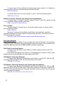
4.1
Field Separators
Fields are separated by white space, that is any number of spaces or tabs as long as
the entire command is less than 256 characters. A <cr> terminates the command. Below is an
example describing a command.
EX
05
<cr>
So the actual message would look like this:
EX 05<cr>
4.2
Command Request Syntax:
This document uses the following notation when describing the syntax of a command
request:
BOLD – identifies the command
lower case – identifies data to be entered which is described in the text following the
syntax description
““
- entry defined within double quotes is to be entered exactly as shown
<>
- entry defined within these brackets is required
[ ]
- entry defined within these brackets is optional
{}
- entry defined within curly brackets must be entered at least once
|
- a vertical bar denotes a logical choice of entry
*
- an asterisk following either [ ] brackets or curly brackets { } above denotes that
data within either brackets or curly brackets may be entered multiple times.
number sequence – this refers to a single number or a sequence of numbers, each
number separated from the next by a comma and may also include a range of numbers (e.g.
1,3,5,7-11, 12, 16)
4.3
Command Request Comment Fields
The ASCII syntax of the request protocol accommodates the ability to optionally insert
comments into the Command Request. Comments must be enclosed within the #
character. This feature was intended to facilitate user descriptions of the audio and video
which they are configuring but may, of course, be used however the user sees fit. The
12
comments are ignored by the MatrixPRO-II but, of course, add to serial transmission
overhead.
Example:
Below is an example of uncommented connection commands.
CON 1 (1) 2 (2-4) 1F(1)<cr>
VOL L 1 –45<cr>
The above could have comments added as follows:
CON 1 # Sony DVD # (1) 2 (2-4)
VOL L 1 –45
# Configures training rooms A,B, and C #<cr>
# Initialize output 1 to floor of –45 dB #<cr>
13
5 Acknowledging Receipt of Commands
Each request sent to the MatrixPRO-II have by default two possible responses, an
acknowledgement of a correct request or an error response. The acknowledge response will
be:
Ok<cr><lf>.
The MatrixPRO-II may also be configured via command (see below) to suppress all
responses. The user should exercise care when configuring no response as the user will
obviously have no feedback as to the success of the command.
The user may also wish to receive an echo of the command that was sent along with
the acknowledgement. This is configurable via the ECH command (see below). Echoing of
commands may be of use to serial users attempting to distinguish the original command to
which an acknowledgement has been sent. An example appears below of a command and the
echoed response.
Command:
CON 1 (1) 2 (3-5)<cr>
Response with echo:
CON 1 (1) 2(3-5)<cr><lf>
Ok<cr><lf>
6 Error Response
In the event an invalid command is sent to the MatrixPRO-II, it will respond with the
message “ERR: unknown command“. If an invalid parameter is sent to the MatrixPRO-II,
the unit will respond with the message “ERR: “ followed by the valid syntax for the errored
entry.
Example:
A connect request with an incorrect input number:
CON 0 (8)<cr>
The error response would be:
ERR: CON {<input>[card specifier] <”(“numberSequence”)”>}*<cr>
Note that the returned error response may be expanded to a more detailed version by entering
verbose mode. This mode may be turned on by issuing a VRB Y command. The expected
syntax for the command will be returned, as above, and a description of each parameter.
For example, if verbose mode were turned on and the above command issued, the response
would be:
ERR: CON {<input>[card specifier] <"("numberSequence")">}*<cr>
CON {<input>[card specifier] <”(“numberSequence”)”>}*<cr>
Connect the specified input to specified output.
14
input
card specifier
numberSequence
Input number in the range 1 – max inputs
optional indicator of the card type with “A”,”B”or”C”
(applicable to split mode) designating video and “F”
designating audio.
Outputs as number sequence in range 1 - max outputs.
7 MatrixPRO-II Configuration
During production the unit will be configured with a configuration file that will contain
matrix type, total inputs, total outputs, volume calibration, and serial number. This eliminates
the need for jumpers or dipswitches.
15
8 Split Mode
The video cards on the MatrixPRO-II contain inputs and outputs. Signals that enter
through an input can only be switched to outputs on the same physical card. The design of the
video boards does not allow switching signals between video cards.
The majority of users will use the unit for the flavor it was built for. That is, all RGB, all
S-Video, all Component or all Composite. There is no special setup required to describe the
inputs and outputs in their native signal types as each input and output default type is its native
type. However, some users might wish to use unallocated constituent video signals, say for
RGB for other signal types such as S-Video or Composite. This is known as split mode.
The user will be able to split the inputs/outputs of a RGB, Component or S-Video matrix.
The inputs/outputs on a RGB matrix will default to Red, Green, and Blue components, but they
may be defined as representing combinations of composite and/or the two S-Video signals.
One basic recommendation is that if you assign the two S-Video components (“Y” and
“C”) to the green and blue cards on an RGB matrix, then any other S-Video inputs or outputs
should also be assigned to the green and blue video cards. The user can still use the red card
for composite. This will take some of the complication out of the setup process.
It is important that the user realize one very hard and fast rule; that inputs defined as
residing on a video card can ONLY be connected to an output residing on that same card.
This is because the representative A, B, and C input signals are only physically connected to
their respective output card type. For example; if input 14 is defined as a composite video on
the red video card it can only be connected to an output that is also a composite video residing
on the red video card. The same goes for S-Video, if input 16 is defined as a S-Video on the
green/blue video cards it can only be connected to an S-Video output on the green/blue video
card. Failure to follow this rule will result in unexpected results.
8.1
RGB matrix used in Split Mode
The user can define the three video cards as Component video
The user can also define one card for composite video, and the remaining two for SVideo. If the user uses the red card for composite video it would make sense that all
subsequent composite video inputs or outputs should reside on the red card. The user has the
same rule with S-Video, if the user defines green/blue card input for S-Video, then all S-Video
inputs or outputs should be on the green/blue boards. If green/blue is used for S-Video, the
red card may be used for composite video.
The only definition that is not allowed on a RGB matrix is S-Video on the red and blue
video cards.
16
9 MatrixPRO-II REQUEST LIST QUICK REFERENCE
REQUEST
AVT
CBL
CFG
CON
DEL
DIS
ECH
FPL/FPU
HLP
INP
MOD
MUT
NAM
OUT
PST
RFD
RSP
RGB
STA
STD
SYN
VER
VOL
VRB
DESCRIPTION
Audio type selection
Cable length configuration
Configuration Request
Connection Request
Delay Request
Disconnect Request
Echo Commands Request
Front Panel Lock/Unlock Request
Help
Input port Setup
Model request
Mute
Assign names to inputs and outputs
Output port setup
Preset Requests
Return to Factory Defaults Request
Response
RGB Delay Request
Status Requests
Set time/date
Sync Equalization
Request version numbers
Volume request
Verbose
17
10 Audio Type
The user will be able to select the type of audio input, Professional or Consumer, with
the AVT request. Factory default setting is Consumer for all inputs. The format of the AVT
request is as follows:
AVT
“P”|”C”
inputSequence
<cr>
Syntax: AVT <”P”|”C”> <inputSequence><cr>
Where:
AVT
Audio type request
“P”|”C”
P for professional, C for Consumer
inputSequence
Input number sequence in range of number of inputs
Example:
AVT P 1, 4-8
Sets inputs 1 and 4 thru 8 to professional.
18
11 Cable Length Request
The cable length request gives the user the ability to set the length of cable from
the unit to the display for outputs or the length of cable from the source to the unit. The
settings are from 0 to 150 feet in increments of 10 feet represented by the values 0-15. Zero
feet is off. Factory default setting is a length of 0 for all inputs and outputs.The format of the
cable length request is as follows:
CBL
“I”|”O”
length|”?”
numberSequence
<cr>
Syntax: CBL <”I”|”O”> <length|”?”> <numberSequence><cr>
Where:
CBL
Cable length request header
“I” | “O”
I=Input, O=Output
length
0 (off) to 15 representing 10’ increments, or “?” for inquiry
numberSequence The input or output number sequence being assigned a length.
Example:
CBL I 5 2,4-6<cr>
Sets inputs 2, 4, 5, and 6 to a cable length of 50 feet.
19
12 Configuration Request
The Configuration request is used to obtain the unit’s model number. The model
number describes the number of inputs and outputs, the type of the matrix, audio functionality,
and equalization functionality.
The format for the configuration request is as follows:
CFG
<cr>
Syntax: CFG<cr>
Where:
CFG
Configuration request
Example:
CFG<cr>
For a 16x16 RGB matrix with audio and equalization functionality the response will be:
MSRF-1616
The returned text will be one of the following:
MSR-1208
MSRC-1208
MSRD-1208
MSRF-1208
MSR-1616
MSRC-1616
MSRD-1616
MSRF-1616
MSR-3232
MSRD-3232
20
13 Connection Request
The connection request is used to connect an input to one or more outputs. The unit
checks the signal type of the input and output and if they are compatible then the unit connects
them. (By default, the signal inputs and outputs are compatible as they represent their native
matrix type. Only when inputs and outputs are designated as split using the INP/OUT
request does this present a concern.) Connections may be disconnected by using the DIS
command (see later in document).
CON
input[card specifier]
“(“numberSequence”)”
<cr>
Syntax:
CON {<input>[card specifier] <”(“numberSequence”)”>}*<cr>
Where:
CON
Connection request header
input
Input number in the range 1 – max inputs.
card specifier
Optional indicator of the card type with “A”,”B”or”C” (applicable to split
mode) designating video, and “F” designating audio.
numberSequence Outputs as a number sequence.
Split Video Connections
The connection request can be used to connect split inputs and outputs. For split video
connection requests the user needs to specify “A”,”B”, or “C” following the input number
followed by the output number being connected. The output number need not contain the card
specifier since if the output has been previously identified as split using the OUT command
and is of the same card type then the card specifier is understood to be the same as that
designated with the input number. Audio connections may be thought of as ‘split’ and always
residing on the “F” card, so audio connection inputs need to designate an F along with the
input.
For example, if the user wanted to connect input 14A to output 14A and both have been
previously defined as S-Video for instance then the user need only designate the “A” specifier
on the input since the association to ouput on the A card is understood. If the user wanted to
connect audio of input 10 then an “F” would have to be included for the input. If the requested
input type is not compatible with any of the specified output types then the request will be
rejected and an incompatibility error reported (see below).
To connect an input to multiple outputs separate the outputs with a comma. The last
output is followed by a carriage return. Partially compatible connection requests will result in
the entire request being rejected and an incompatibility error reported (see below).
Single Connection Example:
To connect input 5 audio to output 4 the connection request would look like this:
CON 5F (4)<cr>
Multiple Connection Example:
21
To connect input 10 video defined as its native matrix type to outputs 2, 4, 8 defined as
the native matrix type the connection request would look like this:
CON 10 (2,4,8)<cr>
To connect audio input 3 to audio outputs 3, 4 and 11 send the following request:
CON 3F (3,4,11)<cr>
Multiple Connection Example (with multiple input designations):
To connect input 1 to output 3, input 4 to outputs 2,4, and 7, input 10 to outputs 8,9, and
10, the connection request would be as follows:
CON 1 (3) 4 (2,4,7) 10 (8,9,10)<cr>
Error Example:
The user attempts to connect input 1, previously defined as split, to outputs 8 and 9.
with the following request:
CON 1 (8,9)<cr>
Since input 1 was previously defined as split then a card specifier is required to
completely characterize the type of split connection being connected. The above command
will result in the error response:
CON ERR: One or more incorrect connection specifications detected.
Split Video Examples
The following are examples of how to connect split video on the matrix. Note that prior
to attempting split connections, the prospective split inputs and outputs to be connected must
have been defined as split with the INP and OUT commands respectively.
Split Single Connection Example:
To connect input 5B video to output 4B the connection request would look like this:
CON 5B (4)<cr>
Note that the card specifier for output 4 is not designated since card B for output 4 has
already been previously defined as the same type as that of 5B.
Split Multiple Connection Examples:
To connect input 5B previously defined as split S-Video to outputs 12B, 13B, and 16B
previously defined as split S-Video, the user would issue this request:
CON 5B (12,13,16)<cr>
Split Multiple Connection Example (with multiple input designations):
To connect input 5B previously defined as split S-Video to outputs 12B, 13B, and 16B
previously defined as split S-Video, input 7A previously defined as Composite to outputs 13A,
16A, and 17A previously defined as Composite, and input 6 audio to output 6 and 7 audio the
user would issue this request:
CON 5B (12,13,16) 7A (13,16,17) 6F (6,7)<cr>
22
14 Delay Request
Some devices require a delay when switching RGB. The delay request enables or
disables the delay for the output. Since this is a RGB function it will not be available on SVideo or composite ports.
NOT CURRENTLY IMPLEMENTED
DEL
“E”|”D”|”?”
outputSequence
<cr>
Syntax: DEL <”E”|”D”|”?”> <outputSequence><cr>
Where:
DEL
Delay request header
“E”|”D”
E=Enable, D=Disable
outputSequence
Output as a number sequence.
“?”
Inquiry for the specified output number(s)
Example:
To enable RBG delay for outputs 2, 4, 10, 12-15, and 24 the user would send the
following message:
DEL E 2,4,10,12-15,24<cr>
The matrix would respond to this message with an OK response.
The matrix will respond with this message to an inquiry of output 12 if output 12 was
enabled.
DEL ? 12<cr>
DEL E 12
To get the current status of all the output delays on a 16X8 matrix the user would send
the following message:
DEL ? 1-8<cr>
The response would be the following if an output delay on outputs 1-4 are currently
enabled and outputs 5-8 currently disabled.
DEL E 1,2,3,4 D 5,6,7,8
23
15 Disconnect Request
The Disconnect request is used to disconnect a specified output from its input. The unit
checks the specified signal type of the output to ensure that it is indeed of that type before
attempting to disconnect.
DIS
output[cardSpecifier][“,”output[cardSpecifier]
<cr>
Syntax: DIS <output[cardSpecifier][“,”output[cardSpecifier]]*<cr>
Where:
DIS
Disconnect request header
output
Output being disconnected.
cardSpecifier
Optional card specifier “A”, “B”, or “C” for split mode disconnects or “F” for
audio disconnects.
Example:
To disconnect video outputs 1, 3, 5-9, all defined as non-split the user would send the
following message:
DIS 1,3,5,6,7,8,9<cr>
To disconnect video outputs 1B, 3A, 4C (all defined as split), video outputs 2 and 5
(non-split), and audio output of 1 and 10, the user would send the following message:
DIS 1B,3A,4C,2,5,1F,10F<cr>
If the user attempted to disconnect a video output defined as split without the proper
card specifier then an error would be reported. In the example below, the user attempts to
disconnect output 10, defined as split with Composite on A card and S-Video on B and C
cards.
DIS 10<cr>
DIS ERR: Ambiguous disconnect specification
If the user attempted to disconnect a video output defined as non-split with an optional
card specifier, which in this case would be improper, then an error would be reported. In the
example below, the user attempts to disconnect output 10B. Since output 10 is defined as
non-split this generates an error response.
DIS 10B<cr>
DIS ERR: Improper disconnect specification
24
16 Echo Commands Request
This request allows the user the configure whether an echo of the originally received
serial command is output back to the sender. Echoing of commands may be of use to serial
users attempting to distinguish the original command to which an acknowledgement has been
sent. Echo of commands defaults to OFF and is reset to OFF on a power cycle.
The format for this request is as follows:
ECH[O]
“ON”|”OFF”
<cr>
Syntax: ECH[O] <“ON”|”OFF”><cr>
Where:
ECH
Echo request header.
“ON”|”OFF”
ON to enable echo, OFF to disable.
Example:
To enable echoing of commands the user would send the following message:
ECH ON<cr>
The matrix will respond with an Ok message.
To disable echoing of commands:
ECH OFF<cr>
25
17 Front Panel Lock/Unlock Request
This request is used to disable/enable configuration of the MatrixPRO-II via the Front
Panel interface. When the Front Panel is locked a message will be displayed on the FP
interface screen indicating such and all button action will be disabled. It may only be unlocked
via the appropriate serial request. Front Panel use defaults to unlocked and is reset to
unlocked on a power cycle.
The format for this request is as follows:
FPL | FPU
<cr>
Syntax: FPL | FPU<cr>
Where:
FPL
Lock the Front Panel interface.
FPU
Unlock the Front Panel interface.
Example:
To lock the Front Panel interface the user would send the following message:
FPL<cr>
The matrix will respond with an Ok message.
To unlock the Front Panel Interface:
FPU<cr>
26
18 Help Request
The user will be able to request a list of the valid commands with descriptions and
formats. The format for this request is as follows:
HLP
[cmd]
<cr>
Syntax: HLP [cmd]<cr>
Where:
HLP
Help Request header
cmd
optional command identifier
If the optional cmd is omitted, the matrix will respond with the following text message:
AVT
CBL
CFG
CON
DEL
DIS
ECH
FPL
FPU
HLP
INP
MUT
NAM
OUT
PST
RFD
RGB
RSP
STA
STD
SYN
VER
VOL
VRB
Audio type selection
Configures cable length
Configuration request
Connection request
Delay enable/disable request
Disconnect request
Echo request
Front Panel lock-out request
Front Panel unlock request
Help
Input setup request
Mute output volume
Assign names to inputs and outputs
Output setup request
Preset requests
Return to Factory Default Request
RGB Delay request
Response from Matrix request
Status requests
Set time/date
Sync equalization request
Version Numbers
Volume request
Verbose
Entering HLP <cmd><cr>, where cmd is any valid Matrix command in the above list, will
return specific help syntax for the command requested. If the user would like more detailed
help for a specific command then it is necessary to turn on verbose mode using the VRB Y
command syntax. This will enable returning a description of the parameters of any specific
command. The user may return to non-verbose mode by issuing the VRB N command.
Specific command help is listed below:
AVT <”P”|”C”> <inputSequence><cr>
27
Select the type of audio for the specified input.
“P”|”C”
P for professional, C for Consumer
inputSequence
Input number sequence in range of number of inputs
CBL <”I”|”O”> <length|”?”> <numberSequence> <cr>
Configure cable lengths.
“I” | “O”
I=Input, O=Output
length
0 (off) to 15 in 10’ increments, or “?” for inquiry
numberSequence The input or output number sequence being assigned a length.
CFG <cr>
Returns formatted text describing the matrix configuration.
CON {<input>[card specifier] <”(“numberSequence”)”>}*<cr>
Connect the specified input to specified output.
input
Input number in the range 1 – max inputs
card specifier
optional indicator of the card type with “A”,”B”or”C” (applicable to
split mode) designating video and “F” designating audio.
numberSequence Outputs as number sequence in range 1 - max outputs.
DEL <”E”|”D”|”?”> <outputSequence><cr>
Enable/Disable delays for specified outputs.
“E”|”D”
E=Enable, D=Disable
outputSequence
Output as a number sequence.
“?”
Inquiry for the specified output number(s)
DIS <output[cardSpecifier][“,”output[cardSpecifier]]*<cr>
Disconnect specified outputs.
output
Output being disconnected.
cardSpecifier Optional card specifier “A”, “B”, or “C” for split mode disconnects or “F”
for audio disconnects.
ECH[O] <“ON”|”OFF”><cr>
Enable/disable echoing of commands.
“ON”|”OFF”
ON to enable echo, OFF to disable.
FPL | FPU<cr>
Front Panel Lock/Unlock command.
HLP [cmd]<cr>
Provides help for MatrixPRO-II command set.
cmd
optional command identifier
INP | OUT <number> {<”A”|”B”|”C”><”:”><type>}*<cr>
Specifies input or output configuration applicable to split mode.
number
Input or output number.
“A”|”B”|”C” A=R card, B=G card, C=B card for RGB matrix
A=Y card, B=U card, C=V card for Component matrix
28
type
A=Y card, B=C card for S-Video matrix
1=RGB, 2=S-Video, 3=Composite, 4=Component
MOD <”’”modelType”’””><cr>
Specifies the model type of the matrix.
“’”modelType”’”
The model type string per pre-specified allowed values.
MUT <”M”|”U”> <outputSequence><cr>
Mutes or unmutes the specified output.
“M”|”U”
M=mute, U=unmute
outputSequence
Output as number sequence to be muted/unmuted.
NAM <”I”|”O”> <number> <name|”?”><cr>
Assigns an ASCII string to the specified input/output.
“I”|”O”
I for input, O for output
number
Input or output number
name
Optionally (i.e. no ?) assign alphanumeric name12 ASCII characters or
less to specified input or output number enclosed with double quotes.
“?”
Optionally inquire a previously specified assignment.
PST <”S”> <presetNumber>
<outputNumber[cardSpecifier]>[<”,”outputNumber[cardSpecifier]>]*<cr>
Sets and saves the specified preset to memory.
“S”
S=Save preset request
presetNumber
Preset in range of 1 to 32.
outputNumber
Output number 1 – max number of outputs.
cardSpecifier
Optional card specifier if output is split.
PST <”R”> <number><cr>
Recalls a previously specified preset.
“R”
R=Recall and execute preset request.
number
Preset to recall.
RFD <"Y"|"N"><cr>
Return to factory default settings.
"Y"|"N" Y=return to factory defaults, N=don't return
RGB <time><cr>
Specify an RGB delay.
time
Amount of time in tenths of seconds from 1 to 100 in ASCII.
RSP <”Y”|”N”><cr>
Allows suppression of serial responses from matrix.
“Y”|”N”
Y = response enabled, N = response disabled
STA <”I”|”O”> <number | “A”><cr>
Returns status for specified inputs or outputs.
29
“I”|”O”
number
”A”
STA
}*
I input, O output
Input or output number.
A to designate all respective input or output.
Status returns the following if Input requested:
{ <MatrixType> <InputNumber> <TrimValue> <SplitStatus> [CardSpecifier”:”CardType]
MatrixType
InputNumber
TrimValue
SplitStatus
CardSpecifier
CardType
1=RGB, 2=S-Video, 3=Composite, 4=Component
The requested input.
The trim value in range –10dB to +10dB for the specified
Y if split, N otherwise
If split : A, B, or C specifying split signal type.
If split: 2 designating S-Video or 3 designating Composite.
Status returns the following if Output requested:
STA { <MatrixType> <OutputNumber> <DelayStatus> <MuteStatus> <AudioLevel>
<AudioInputConn> <SplitStatus> [<VideoInputConn> |
[<CardSpecifier”:”CardType”,”VideoInputConn>]* ] }*
MatrixType
1=RGB, 2=S-Video, 3=Composite, 4=Component
OutputNumber
The requested output.
DelayStatus
RGB delay, E=enabled, D=disabled.
MuteStatus
M=Muted, U=Unmuted.
AudioLevel
The audio output level for the specified output in range –45dB to
+5dB.
AudioInputConn
The audio input that the specified output is connected to, “255” if
unconnected.
SplitStatus
Y if split, N otherwise
VideoInputConn
The video input that the specified output is connected to, “255” if
unconnected.
CardSpecifier
If split : A, B, or C specifying split signal type.
CardType
If split: 2 designating S-Video or 3 designating Composite.
STD <time> <date><cr>
Sets the time and date.
time
Time in format hh:mma|p
date
Date in mm/dd/yy format
SYN <status> <outputSequence><cr>
Configure Sync equalization
status
“0” for OFF, “1” for ON and “2” for AUTO.
outputSequence
Output as a number sequence.
VER<cr>
Version request returns the following:
VER Matrix Test/Loader = <XX.xx>, Matrix App = <XX.xx>, FP Test/Loader = <XX.xx>, FP
App = <XX.xx>
XX.xx
XX = Major version number, xx = Minor version number.
30
VOL <”L”|”T”> <numberSequence> <value|”?”><cr>
Configures the audio output level or trim for the specified output or input.
“L” | “T”
output Level or Trim
numberSequence The output number sequence if L specified or the input number
sequence if T specified.
value
Volume value -10 to +10 for trims, -45 to +5 for level (in 1 dB
increments) or “+” to increment volume in 1 dB increments, or “-“ to
decrement volume in 1 dB decrements.
“?”
Inquiry for the specified level or trim
VRB <”Y”|”N”><cr>
Enables or disables verbose mode.
“Y”|”N”
Y turns verbose on, N turns verbose off.
31
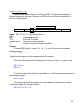
19 Input/Output Request Format
This command allows configuration of the card type for inputs and outputs in
preparation for making split connections. If the user doesn’t intend to ever make split
connections then this command may be ignored. The format of the request is as follows:
INP|OUT
number “A”|”B”|”C”
“:”
type
<cr>
Syntax: INP | OUT <number> {<”A”|”B”|”C”><”:”><type>}*<cr>
Where:
INP
Specifies input configuration
OUT
Specifies output configuration.
number
The input/output number being configured, the range of which is
dependent on the number of inputs and outputs of the matrix.
“A”|”B”|”C”
A = R card, B = G card, C = B card for RGB matrix
A = Y card, B = U card, C = V card for Component matrix
A = Y card, B = C card for S-Video matrix
“:”
colon character ties the card type to the virtual matrix type
type
1 = RGB, 2 = S-Video, 3 = Composite, 4 = Component
Definitions of multiple cards in the same input or output will be separated by a space.
A semicolon will separate multiple input and outputs definitions in the same request.
Example:
To assign input 14 green to S-Video the following command would be used.
INP 14 B:2<cr>
To assign output 15 red to composite the following command would be used:
OUT15 A:3<cr>
To assign input 15 red to composite, and green/blue to S-Video the following request
would be sent:
INP 15 A:3 B:2<cr>
Since S-Video uses two video signals (luminance and chroma), defining the B (green) in
the request above as S-Video means that the luminance will be on the green card and the
chroma on the blue.
To assign output 15 red, green, and blue to composite the following request would be sent:
INP 15 A:3 B:3 C:3<cr>
Although the cards default to RGB on an RGB matrix, the user can still issue this
request to return output 2 to its native RGB.
OUT 2 A:1 B:1 C:1<cr>
Multiple Example:
To assign input 15 red to composite, and green/blue to S-Video and output15 the same
way the following request would be sent:
INP 15 A:3 B:2; OUT 15 A:3 B:2 <cr>
32
20 Model Request
The MOD Model request allows configuration of the model type of the MatrixPRO-II .
This command is normally reserved for use by factory personnel and as such the user must
have logged in correctly with the PSW command. The format for the model request is as
follows:
MOD
“’”modelType”’” |”?”
<cr>
Syntax: MOD <”’”modelType”’””|”?”><cr>
Where:
MOD
Model request header.
“?”
Inquire the MatrixPRO-II model number. Return string is in
format as described below.
“’”modelType”’”
The model type in a format defining the number of inputs and outputs, the
video type, audio card presence, and/or equalization present. The
modelType must be enclosed within single or double quotes. The
modelType must be exactly one of the following:
MSR-1208
MSRC-1208
MSRD-1208
MSRF-1208
MSR-1616
MSRC-1616
MSRD-1616
MSRF-1616
MSR-3232
MSRD-3232
Example:
To configure the matrix model type as 12x8, RGB with audio present and equalization
present the user would issue the following string from the list above.
MOD “MSRF-1208”<cr>
To obtain the model number the user would issue the following command:
MOD ?<cr>
For a 16x8 RGB matrix with audio and equalization functionality the response will be:
MSRF-1608
33
21 Mute Request
The user will be able to mute any audio output by sending the mute request: The
format for the mute request is as follows:
MUT
“M” | “U”
outputSequence
<cr>
Syntax: MUT <”M”|”U”> <outputSequence><cr>
Where:
MUT
Start of mute message
“M”|”U”
M=mute, U=unmute
outputSequence
Output as number sequence to be muted/unmuted.
Example:
MUT M 4<cr> – Mutes the audio output of output 4.
MUT U 8<cr> – Unmutes the audio output of output 8
MUT M 2,6,9,10<cr> Mutes audio outputs 2, 6, 9, and 10.
34
22 Set Input/Output Name Request
The user will be able to set a name for inputs, outputs, and groups. The name can be
up to 12 ASCII characters long. All ASCII characters available on a typical keyboard are
allowed except the double quote character. The name must be enclosed within double quotes.
The set name request is formatted as follows:
NAM
“I”|”O”
number
name|”?”
<cr>
Syntax: NAM <”I”|”O”> <number> <name><cr>
Where:
NAM
Name request header
“I”|”O”
I for input, O for output
number
Input or output number
name
Optionally (i.e. no “?”) assign as many as 12 ASCII characters to specified input
or output number. The name must be enclosed within double quotes.
“?”
Optionally inquire a previously specified assignment.
Example:
To name Input 2 “DVD1” the user would send the following message:
NAM I 2 “DVD1”<cr>
The matrix will respond with an OK response.
Example:
If the user needed the name for input 2 (from example above) the following request
would be sent:
NAM I 2 ?<cr>
To which the matrix would respond:
NAM I 2 “DVD1”<cr>
35
23 Preset Request
There are times when the user will want to specify connections and audio output levels
that can be recalled at a later time. These connections, stored in non-volatile memory, are
called presets. There are 32 presets that may be defined.
Presets are specified using the PST S command using the syntax defined below. A
Preset is composed by selecting a set of outputs, video and/or audio, (and thus their
associated inputs) from the set of existing output connections. It is therefore a subset of the
currently existing output connections from which it was selected. Audio levels for each
selected audio output are captured as part of the preset. Once configured from the existing
output connections, the preset is saved for later execution (using the PST X command below)
and the user is free to modify the existing output connections to accommodate another preset
definition as they like.
It is an error to attempt to include outputs as split that haven’t been defined as split (via
a previous OUT command) or to include outputs as non-split that have been split.
The format for the Preset Save message is as follows:
PST “S” presetNumber outputNumber[cardSpecifier][“,”outputNumber[cardSpecifier] <cr>
Syntax:
PST <”S”> <presetNumber>
<outputNumber[cardSpecifier]>[<”,”outputNumber[cardSpecifier]>]*<cr>
Where:
PST
Preset request header
“S”
S=Save preset request
presetNumber
Preset in range of 1 to 32.
outputNumber
Output number 1 – max number of outputs.
cardSpecifier
Optional card specifier if output is split.
Example:
If a user wanted to set preset 1 to include outputs 1, 3, 5F, 7A, 7C, 8B, 12A, and 15
then the user would issue the following message:
PST S 1 1,3,5F,7A,7C,8B,12A,15<cr>
NOTE: Each preset has each of its outputs initialized to disconnected. When a preset is
defined using the PST S command only those outputs represented in the PST S command are
retained for execution. All previously disconnected outputs in that preset are redefined as
excluded from the preset. The initial disconnected state of an undefined preset allows the user
to execute those presets with the PST G command below to disconnect all outputs.
36
A previously defined preset may be executed using the PST X command, the syntax of which
appears below. The execute command results in the matrix output to input connections and
audio levels being configured as defined in the preset.
PST
“X”|”G”
Number
<cr>
Syntax: PST <”X”|”G”> <number><cr>
Where:
PST
Preset request header
“X”|”G”
X=Execute preset request for the specified number.
G=Get preset settings request for the specified number (Not currently
implemented).
number
Preset to recall in the range of 1 to 32.
Response for Preset Get request:
PST G <PresetNumber> [<InputNumber>[CardSpecifier]
“(“<OutputNumber>[“,”<OutputNumber>]*”)”]*<cr>
Where:
PresetNumber
InputNumber
CardSpecifier
OutputNumber
1 to 32 as originally identified by Number entry in request.
Input number which was part of original connection when preset
originally set.
Card specifier indicating A,B,C if input split or F if audio.
Output number to which the specified input is connected.
Note that the [ ]* syntax in the response describes zero or more occurrences of the data
enclosed within the curly brackets.
Note also that the output to the “G” message is presented in a format similar to that specified
by the CON command.
Example: if the user previously made connections using the CON command to connect video
input 3 to outputs 2,4,6,8, video input 2 to 1,3,5,7 and audio input 9 to 1-8 and defined preset 1
using the PST S command as below:
CON 3 (2,4,6,8) 2 (1,3,5,7) 9F (1-8)
PST S 1 1,2,3,4,5,6,7,8,1F,2F,3F,4F,5F,6F,7F,8F
Then issuing a PST G 1 command would return the following:
PST G 1 2 (1,3,5,7) 3(2,4,6,8) 9F (1,2,3,4,5,6,7,8)
37
24 RGB Delay Request
The RGB Delay request sets the amount of time to delay when switching RGB outputs.
RGB
time|”?”
<cr>
Syntax: RGB <time|”?”><cr>
Where:
RGB
RGB Delay request header
time
Amount of time in tenths of seconds from 0 to 100 in ASCII.
“?”
Inquiry of the currently specified RGB delay.
Example:
To set the RGB delay time to 7.5 seconds, the user would send the following message:
RGB 75<cr>
The matrix will respond with an OK message.
To get the RGB delay time the user would send the following request:
RGB ?<cr>
The matrix will respond with the following for a RGB time of 7.5 seconds:
RGB 75
38
25 Response Request
The user will be able to suppress all responses from the MatrixPRO-II if they like. The
user should ensure that all subsequent requests to the MatrixPRO-II are properly formatted as
it would be difficult to ascertain their correctness without a response. The format for the
Response request is as follows:
RSP
“Y”|”N”
<cr>
Syntax: RSP <”Y”|”N”><cr>
Where:
RSP
Response Request header.
“Y”|”N”
Y = response enabled, N = response disabled
Example:
RSP Y<cr> – Response requested.
RSP N<cr> – Response suppressed.
39
26 Return to Factory Defaults Request
The user can return the unit to factory defaults by issuing this command. The unit
settings affected include cable lengths, RGB delay, Sync equalization, video and audio
connections, audio output and trim levels, mute status, and IP address. After having issued
this command, the user may query the unit settings via the Status Request command. This
command should be exercised with care. The format for the Return-to-Factory-Defaults
request is as follows:
RFD
“Y”|”N”
<CR>
Syntax: RFD <”Y”|”N”><cr>
Where:
RFD
Return-to-Factory-Defaults Request header.
“Y”|”N”
Y = return to factory defaults, N = do not return to factory defaults
Example:
RFD Y<CR> – Return to factory defaults requested.
40
27 Status Request
The user will be able to request status of individual inputs and outputs, all inputs or all
outputs.
STA
“I”|”O”
number|”A”
<cr>
Syntax: STA <”I”|”O”> <number | “A”><cr>
Where:
STA
Status request header
“I”|”O”
I input, O output
number
Input or output number.
”A”
A to designate all respective input or output.
Response for Input Status request:
STA <MatrixType> {<InputNumber> “(“<CableLength>”,”<AudioType>”,”
<TrimValue>”,”<SplitStatus>”,” [CardSpecifier”:”CardType] “)”}*
Where:
MatrixType
InputNumber
CableLength
AudioType
TrimValue
SplitStatus
CardSpecifier
CardType
1 = RGB, 2 = S-Video, 3 = Composite, 4 = Component
The requested input or the enumerated input if “A” specified.
Cable length in 10’ lengths from 00 to 150
P for Professional or C for Consumer
The trim value in range –10dB to +10dB for the specified InputNumber.
Y if split, N otherwise
If split : A, B, or C specifying split signal type.
If split: 2 designating S-Video or 3 designating Composite. (Note that
these are the only valid designations into which a signal may be split.)
Note that the { }* syntax in the response describes one or more occurrences of the data
enclosed within the curly brackets. This captures multiple inputs in the response if an “A” for
All was specified in the request. Each successive input will appear on a separate line.
Response for Output Status request:
STA <MatrixType> {<OutputNumber> “(“<DelayStatus>”,” <MuteStatus>”,” <CableLength>”,”
<SyncEqu>”,” <AudioLevel>”,” <AudioInputConn>”,” <SplitStatus> [<”,”VideoInputConn> |
[<”,”CardSpecifier”:”CardType”,”VideoInputConn>]* ] }*
Where:
MatrixType
OutputNumber
DelayStatus
MuteStatus
CableLength
SyncEqu
AudioLevel
1 = RGB, 2 = S-Video, 3 = Composite, 4 = Component
The requested output or the enumerated output if “A” specified.
RGB delay, E=enabled, D=disabled.
M=Muted, U=Unmuted.
Cable length in 10’ lengths from 00 to 150
Output sync equalization setting, 0= off, 1=On, 2= auto.
The audio output level for the specified output in range –45dB to +5dB.
41
AudioInputConn
SplitStatus
VideoInputConn
CardSpecifier
CardType
The audio input that the specified output is connected to, “255” if
unconnected.
Y if split, N otherwise
The video input the specified output is connected to, “255” if unconnected.
If split : A, B, or C specifying split signal type.
If split: 2 designating S-Video or 3 designating Composite. (Note that
these are the only valid designations into which a signal may be split.)
Note that the { }* syntax in the response describes one or more occurrences of the data
enclosed within the curly brackets. This captures multiple inputs in the response if an “A” for
All was specified in the request. Each successive output will appear on a separate line.
Example:
To get the status of RGB matrix unsplit input 22 the user would send the following
request:
STA I 22<cr>
The matrix would then respond with:
STA 1 22(80,C,-5,N)<cr>
This means input 22 has a cable length of 80, configured to Consumer audio, an audio
trim value of –5 dB and isn’t split.
Example Split RGB:
To get the status of a split input 12 on a RGB matrix the user would send the following
request:
STA I 12<cr>
The matrix would then respond with:
STA 1 12 (70,C,-5,Y,A:3,B:2)<cr>
This response tells the user that the input is split, cable length is 70, configured to
Consumer audio, audio trim value of –5 dB, and that red is defined as a composite, and that
green & blue are S-Video.
Example Output not split RGB
To get the status of non-split output 22 on a RGB matrix the user would send the
following message:
STA O 22<cr>
The matrix will respond with the following
STA 1 22 (D,U, 60,1,–30,2,N,2)<cr>
This response means that the matrix type is RGB, output 22 is delay disabled, unmuted, output
cable length of 60’, sync equalization is On, audio level is –30dB, audio connected to input 2,
not split, and video from input 2 is connected.
42
Example Output Split RGB
To get the status of split output 12 on a RGB matrix the user would request the
following:
STA O 12<cr>
The matrix will then respond with the following:
STA 1 12 (E,M,60,2,-10,12,Y,A:3,14, B:2,10)<cr>
Output 12 is on a RGB matrix, delay is enabled, audio is muted, output cable length of
60’, sync equalization is Auto, audio level is –10 dB, connected audio input 12, Split A is
Composite and connected to input 14A, B&C are S-Video and connected to input 10B&C.
43
28 Set Time and Date Request
The time and date will be required for scheduled tasks on the matrix. The format to set
time and date is as follows:
STD
time
date
<cr>
Syntax: STD <<time> <date>>|<”?”> <cr>
Where:
STD
Set time and date request header
time
Time in format hh:mma|p
Where:
hh=hour(1-12)
“:” colon
mm=minute (00-59)
a|p “a” for am, “p” for pm
date
Date in mm/dd/yy format
“?”
Inquires the current time and date and returns the same in format above.
Example:
To set the time and date to noon, June 2, 2006 the user would send the following
message:
STD 12:00p 06/02/06<cr>
To inquire the current time and data:
STD ?<cr>
The unit will respond with:
STD 12:00p 06/02/06
44
29 Output Sync Equ Request
The output sync equ request is only available on RGB units and sets the Sync equ to
ON, OFF, or AUTO. The format of the output sync equ request is as follows:
SYN
status
outputSequence
<cr>
Syntax: SYN <status> <outputSequence><cr>
Where:
SYN
Output Sync Equ request header
status
“0” for OFF, “1” for ON and “2” for AUTO.
outputSequence
Output as a number sequence.
Example:
SYN 2 1,3<cr>
Sets outputs 1 and 3 to AUTO.
45
30 Version Request
The user may request the firmware version numbers. These version numbers will be for
the matrix test/loader, matrix application, front panel test/loader, and front panel application.
The format for the request will be as follows:
VER
<cr>
Syntax: VER<cr>
Where:
VER
Version Request header.
Response: VER Matrix Test/Loader = <XX.xx>, Matrix App = <XX.xx>, FP Test/Loader =
<XX.xx>, FP App = <XX.xx>
Where:
XX.xx
XX = Major version number, xx = Minor version number.
Example:
VER<cr>
To which the Matrix will respond:
VER Matrix Test/Loader = xx.xx, Matrix App = xx.xx, FP Test/Loader = xx.xx, FP App =
xx.xx<cr>
46
31 Volume Request
The Volume request is used to adjust input trims or output level. It can also be used to
inquire about the current value of an input trim or output level. The trims and levels can be set
as a value, or adjusted up or down with “+” or “-“. Multiple consecutive “+” or “-“ characters
may be entered, with each representing a 1 dB increment or decrement respectively.
VOL
“L”|”T”
number
val|”?”
<cr>
Syntax: VOL <”L”|”T”> < number > <value|”?”><cr>
Where:
VOL
Volume request Header
“L” | “T”
output Level or Trim
number
The output number if L specified or the input number if T specified.
value
Volume value -10 to +10 for trims, -45 to +5 for level (in 1 dB increments)
or “+” to increment volume in 1 dB increments, or “-“ to decrement volume
in 1 dB decrements.
“?”
inquiry for the specified level or trim
Example:
VOL L 4 -5<cr>
Instructs the matrix to set output 4 audio level to -5dB.
VOL L 4 +++<cr>
Instructs the matrix to increase output 4 audio level +3dB.
47
32 Verbose Request
The user can, during debugging, turn on verbose mode to expand the standard error
message describing the syntax to include a description of the command parameters.
VRB
“Y’|”N”
<cr>
Syntax: VRB <”Y”|”N”><cr>
Where:
VRB
Verbose request header
“Y”|”N”
Y turns verbose on, N turns verbose off.
Example:
If the user tries to connect and invalid input or output, the standard error message would
look something like this:
ERR: CON {<input>[card specifier] <”(“numberSequence”)”>}*<cr>
If the user enabled verbose mode then the response would be as follows:
ERR: CON {<input>[card specifier] <”(“numberSequence”)”>}*<cr>
Connect the specified input to specified output.
input
Input number in the range 1 – max inputs
card specifier
optional indicator of the card type with “A”,”B”or”C” (applicable to
split mode) designating video, “D” and “E” designating Horizontal
and Vertical sync respectively and “F” designating audio.
numberSequence Outputs as number sequence in range 1 - max outputs.
48
49