1
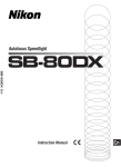
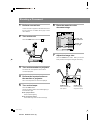
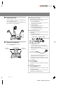
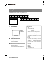
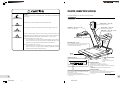
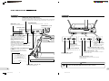
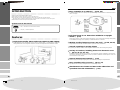
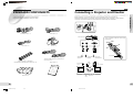
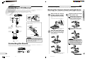
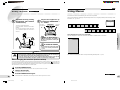
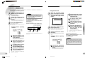
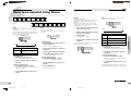
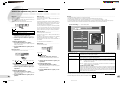
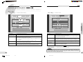
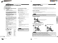
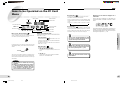
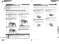
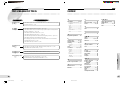
Quick Reference Button for Basic Operations REVERSE button, NEGA and BLUE indicators POWER indicator For a negative image, press the button. Each time you press the button, the display changes in the sequence: Normal H Black & White Reversal (NEGA indicator lights) H Blue display (BLUE indicator lights) H Normal, and so on. It lights when the power is on. BRIGHTNESS buttons Press to adjust the brightness of the screen. Operation panel 2 MENU button Press to turn the menu display on/off. E-ZOOM button/indicator Press the button to activate the electronic zoom function. The indicator lights, and the image is enlarged 2 or 4 times. When you press the button again, the function is deactivated, and the indicator goes dark. LIGHTS button/UPPER and LOWER indicators Press the button to light the fluorescent lamps. Each time you press the button, the illumination changes in the sequence: Upper lamps on (UPPER indicator lights) H Lower lamps on (LOWER indicator lights) H Both off, and so on. POWER switch Operation panel 1 TONE button/indicator Press the button to sharpen the image. The indicator lights. When you press the button again, the TONE function is deactivated and the indicator goes dark. Using the menu, fine adjustment in 5 steps can be made. FOCUS 8 / 9 buttons Press to focus on the document. For automatic focusing, press both buttons simultaneously. • These buttons are also used for menu operations from the operation panel. ZOOM W/T buttons FREEZE button Press to freeze the image on the screen when changing the documents. When the Freeze function is active, the freeze mark is displayed. Press again to release the Freeze function. • The Freeze function is valid only for the monitor or projector screen connected to the RGB connector of this unit. • This button is also used for menu operations from the operation panel. To adjust the size of the image. Press the ZOOM T button to enlarge the image. Press the ZOOM W button to widen the area to be captured. • These buttons are also used for menu operations from the operation panel. 2001.1.9, 9:48 AM 560424 BARCO Quick (E) Shooting a Document 1 Perform connections. 6 Connect a monitor or projector to the RGB connector on Place the material on the document stage. the rear of this unit. For details, refer to page 13 of the User’s Manual. 2 Top Turn on the unit. 297 mm × 420 mm width wide Press the POWER switch down to the side. 210 mm × 297 mm upright approx. Bottom POWER 7 Adjust the image size. Press the ZOOM W or T button. When you hold the button pressed, the image size changes continuously. 3 Turn on the monitor or projector. For details, refer to the operation manual for the connected equipment. 4 Perform the input selection on the monitor or projector. ZOOM W T Set it so that the picture from this unit is displayed. 5 Turn on the lamps. ZOOM W button ZOOM T button Press the LIGHTS button. Press to widen the area to be captured. Press to enlarge the image (max. 6 times). Pressing the button switches the overhead lighting to the lower built-in light. L For opaque material Use the overhead lighting. L For transparent material Use the built-in light under the document stage. **BARCO Quick(E) 2 560424 BARCO Quick (E) 8 Adjust the focus. L Using the Freeze function Press the FOCUS 8 and 9 buttons simultaneously. The When changing the materials, you can eliminate operator’s hands being seen on-screen. focus is adjusted automatically. 1 For fine adjustment, lightly tap the FOCUS 8 or 9 Press the FREEZE button. Press the button before removing the material. The image will be frozen on the screen. button until correct focus is obtained. 2 Change the material. The original image stays on the screen. 3 Press the FREEZE button again. The Freeze function is deactivated, and the image of the new material appears on the screen. L Using the Pen function You can draw lines or circles using a mouse for smooth presentations. 1 Display the PC Card menu. Right-click on the area in the lower four-fifths of the screen. FOCUS AF Red-Pen button Green-Pen button Blue-Pen button 9 Adjust the brightness. 2 Press the BRIGHTNESS + or – button. Select the pen colour. Left-click on the Red-, Green-, or Blue-Pen button. The pointer changes to a pen icon of the selected colour. 3 The image becomes dark. BRIGHTNESS – + The image becomes bright. Draw a line using the pen icon. Drag the pen icon (move it while holding the left mouse button pressed). You can draw a line on the screen as desired. • The lines drawn with the Pen function will disappear when another image on the PC card is displayed. • To deactivate the Pen function, click the right mouse button. • For details on PC cards, refer to pages 33 to 37 of the User’s Manual. L For a clear image Press the TONE button. The contrast of the image is emphasized, making the image clear. L Using the electronic zoom Press the E-ZOOM button. The electronic zoom function is activated, and the E-ZOOM indicator lights. The image size becomes two or four times that adjusted with the ZOOM W/T buttons. 2001.1.9, 9:48 AM 560424 BARCO Quick (E) Using Menus Further detailed adjustments and settings can be made using the menus. There are two methods for menu operations; using the operation panel and using a mouse. The method using a mouse is discussed here. Lights Lights Gain 1 Gain WBset Tone Reverse Color Sharpness WBset Iris A/M Fit/ Over Change Pointer Save to Save to card Server SXGA /XGA Tone Test Reverse arpness Sharpness Color Iris A/M Fit/ Over Display menus. Right-click on this area. Screen of the connected monitor or projector Select the menu icon. Move the pointer onto the menu icon to be selected. The status (settings of the menu items, etc.) of the menu is displayed beneath the icon. 3 Execute the selection. Click the left mouse button. You can now change setting values on the selected menu. • For details on each menu setting, refer to pages 24 to 31 of the User’s Manual. **BARCO Quick(E) 1 560424 BARCO Quick (E) Change Pointer Save to Card Save to Server SXGA /XGA Setup Major menu icons Right-click on the area in the upper one-fifth of the screen. 2 Iris A/M L Tone To adjust the picture tone. • Natural: For ordinary documents • Linear1: To output an image as-is without compensation • Document: For documents with fine characters • Linear2: For glossy documents (the brightness will be decreased.) • Picture: For photos and colour printed matters L Sharpness To adjust the image contours, which can be adjusted in 6 steps. L Iris A/M To alternately select automatic and manual iris adjustments for the camera. Normally select Auto. • Auto Exp. ON: To activate the Auto Iris function • Auto Exp. OFF: To deactivate the Auto Iris function Use the BRIGHTNESS +/- buttons on the operation panel 2 when adjusting the brightness. L Save to Card To save image data on a PC card. Set “File Type” of “Timer ... Setting” of the Setup menu in advance. L SXGA/XGA To switch the output mode. **BARCO ï -ï (E) 44-45 2000.7.18, 8:12 PM Federal Communications Commission (FCC) Radio Frequency Interference Statement This equipment has been tested and found to comply with the limits for a Class B digital device, pursuant to Part 15 of the FCC Rules. These limits are designed to provide reasonable protection against harmful interference in a residential installation. This equipment generates, uses, and can radiate radio frequency energy and, if not installed and used in accordance with the instructions, may cause harmful interference to radio communications. However, there is no guarantee that interference will not occur in a particular installation. If this equipment does cause harmful interference to radio or television reception, which can be determined by turning the equipment off and on, the user is encouraged to try to correct the interference by one or more of the following measures: [ Reorient or relocate the receiving antenna. [ Increase the separation between the equipment and receiver. [ Connect the equipment into an outlet on a circuit different from that to which the receiver is connected. [ Consult the dealer or an experienced radio/TV technician for help. Modifications The FCC requires the user to be notified that any changes or modifications made to this device that are not expressly approved by Barco Projection Systems may void the user’s authority to operate the equipment. Power supply Contact us immediately [ This unit operates on 100 V to 240 V AC. Use only the power cable shipped with the unit. Do NOT use another cable. Doing so may lead to fire or electric shock. If the power cable is damaged or lost, ask your dealer for replacement. [ Ground must be connected at the AC outlet. A leak can cause an electric shock. (☞ p.17) Connect ground Handling the unit [ Some parts inside the unit carry high voltage. Internal repairs must not be attempted by the user. Notice for customers in Canada CAUTION This Class B digital apparatus meets all requirements of the Canadian Interference Causing Equipment Regulations. Do NOT make repairs yourself ATTENTION Cet appareil numérique de la classe B respecte toutes les exigences du Règlement sur le matérial brouilleur du Canada. [ Should any object or liquid enter the unit, immediately turn off the power and consult your dealer. Notice for customers in European countries ACHTUNG Dieses Gerät entspricht den Bestimmungen der EG-Direktive 87/308/EEC zur Störungsunterdrückung. Lärmemission kleiner 70 dBA. Safety Precautions Ask for repairs immediately Operate with care ○○○○○○○○○○○○○○○○○○○○○○○○○○○○○○○○○○○○○○○○○ To ensure safe and correct usage, observe the following precautions: • Before operating the BARCO PRECA 1280 i, read these Safety Precautions thoroughly to ensure safe and proper operation of the unit. • The precautions given here contain important instructions to ensure safe usage of the product. Be sure to observe these precautions. • KEEP THIS MANUAL HANDY FOR ANYONE WHO USES THE UNIT. [ Do NOT block the ventilation holes of the unit. If they are blocked, heat will build up and may cause fire. Do NOT block the ventilation holes Operate with care Set the POWER switch to OFF Examples of picture symbols Do NOT make repairs yourself NEVER do it (symbol for prohibited action). Do NOT make repairs yourself [ The unit has built-in fluorescent lamps in the base for transparent material. Do NOT apply excessive force or shock. If the built-in fluorescent lamps are damaged, consult your dealer. For repair, special devices are required. NEVER attempt repair by yourself. [ Do NOT use the unit in a humid or dusty area. Such conditions may lead to fire or malfunction. Operate only in a proper environment [ When this unit is used for a long time, the bottom of the unit becomes hot. Do NOT leave the unit on a heat-sensitive surface, such as a plastic sheet. ALWAYS follow the instruction (symbol for required action). Unplug power plug from receptacle Install only in a proper environment 2 **BARCO 002-004(E) [ The fluorescent lamps are hot while lit and soon after being turned off. NEVER touch the lamps when hot. To replace or clean the lamps, wait at least 15 minutes for them to sufficiently cool down. (☞ p.38) [ Before replacing the fluorescent lamps, turn off the power to avoid electric shock. (☞ p.38) The symbols used in this manual have the meanings described below. Failure to observe this instruction could lead to personal injury and/or property damage. [ When transporting the unit or when folding the camera head and light blocks, be careful not to get your fingers or clothing caught between the camera head arm and document stage. When extending or folding the arm, do not let go until it locks in place. Otherwise, the arm may fall, pinching your hand or causing damage to the camera block. 3 2-3 2000.7.18, 8:15 PM PARTS IDENTIFICATION Storage [ If the unit will go unused for a prolonged period, ensure safety by disconnecting the power plug. Unplug power plug from receptacle For detailed information, see the pages shown in parentheses. Main Unit [ Store the unit in a place not subject to excessive humidity or dust. Camera head (☞ pp.15, 16) To shoot the document. Store only in a proper environment [ For storage, place the unit horizontally and do NOT place anything on top of it. Light arms (☞ pp.15, 16, 17, 19) To light the document stage. Camera arms (☞ pp.15, 16) For holding the camera head. Light arms (☞ pp.15, 16, 17, 19) To light the document stage. Do NOT place anything on top Use an appropriate power supply [ Use an AC power supply of 50/60 Hz and a voltage of from 100 V-240 V. The appropriate power cable depends on the voltage in the area of use. Using the presentation camera with the wrong cable could result in fire, or electric shock. Fluorescent lamp (☞ pp.12, 17, 38) When using voltage in excess of AC 125 V: Use a power cable in accordance with all safety standards of the country in which it is used, and an AC 250 V plug with a 15 A rating (NEMA 6P-15), and insulation of at least SVT type and more than AWG 18-inch thickness. When using voltage of AC 125 or less: Use a power cable in accordance with all safety standards of the country in which it is used, an AC 125 V plug with a 10 A rating, and insulation of at least SVT type and more than AWG 18-inch thickness. Stopper (☞ pp.15, 16) To fix the camera arm in place. Document stage (☞ p.19) Place a document on the stage. Fluorescent lamps are built in under the stage, and are used for transparent documents. Handle Pull out for carrying the unit. [Operation panel 1] Ventilation holes (☞ p.20) FREEZE FOCUS ZOOM W T AF CARD MENU FREEZE button Press to freeze the image on the screen when changing the documents. (☞ p.20) Press again to release the freeze function. Also used for menu operations from the operation panel. (☞ pp.22, 34) 4 **BARCO 005-007(E) 002-004(E) MENU 5 4 2000.7.18, 8:16 8:15 PM PC CARD slot/eject button (☞ p.33) Insert a PC card. To eject the PC card, press the button. ZOOM W/T buttons To adjust the size of the image. (☞ p.19) Press the ZOOM T button to enlarge the image. When you press the ZOOM W button, the area to be captured is widened. Also used for menu operations from the operation panel. (☞ pp.22, 34) FOCUS 8/9 buttons Press to focus on the document. (☞ p.20) For automatic focusing, press both FOCUS buttons simultaneously. Also used for menu operations from the operation panel. (☞ pp.22, 34) Continue 5 PARTS IDENTIFICATION Continued Main Unit Connectors REVERSE button/NEGA and BLUE indicators For a negative image or display in blue, press the button. Each time you press the button, the display changes in the sequence Normal → Black & White Reversal (NEGA indicator lights) → Blue display (BLUE indicator lights) → Normal, and so on. BRIGHTNESS button Press to adjust the brightness of the screen. (☞ pp.20, 27) MENU button (☞ p.22) Press to turn the menu display on/off. POWER indicator (☞ p.18) It lights when the power is on. [Operation panel 2] MENU E-ZOOM REVERSE NEGA BLUE TONE HI BRIGHTNESS - + LIGHTS UPPER LOWER POWER E-ZOOM button/indicator (☞ p.19) Press the button to activate the electronic zoom function. The indicator lights, and the image is enlarged 2 or 4 times. When you press the button again, the function is deactivated, and the indicator goes dark. MOUSE TONE button/indicator (☞ p.20) Press the button to sharpen the image. The indicator lights. When you press the button again, the TONE function is deactivated and the indicator goes dark. Using the menu, fine adjustment in 5 steps can be made. (☞ p.25) 10Base-T 10Base-T connector (Ethernet) (☞ p.14) For Ethernet connection with a PC, etc. MOUSE connector (☞ p.14) Connect the supplied mouse. Upper lamps on (the UPPER indicator lights.) VIDEO S-VIDEO RGB AC power input connector (☞ p.17) Connect to an AC outlet using the supplied power cable. REMOTE connector (RS-232C) (☞ p.14) Connect to the RS-232C connector of a PC, etc. LIGHTS button/UPPER and LOWER indicators (☞ p.18) Press the button to light the fluorescent lamps. Each time you press the button, the illumination changes in the sequence: ↓ REMOTE RGB connector (D-sub 15-pin) (☞ p.13) Connect to the D-sub 15-pin connector of a video monitor, etc. using the supplied D-sub 15-pin cable. S-video output connector (☞ p.13) Connect to the S-video input of a projector, etc. using the supplied S-video cable. Video output connector (☞ p.13) Connect to the video input of a TV receiver, etc. using the supplied video cable. ↓ Lower lamps on (the LOWER indicator lights.) ↓ Both off, Caution and so on. POWER switch (☞ pp.13, 14, 18) Used to turn the power on/off. Operate with care [ Do NOT connect the public telephone line to the 10 Base-T connector. 6 **BARCO 005-007(E) 7 6-7 2000.7.18, 8:16 PM Safety Precautions ------------------------------------------------ 2 PARTS IDENTIFICATION ------------------------------------------ 5 INTRODUCTION --------------------------------------------------- 10 Features -------------------------------------------------------------- 10 Preparations Operation LShooting a Document --------------------------------------- 18 LCONNECTIONS ------------------------------------------------- 13 LUsing Menus ----------------------------------------------------- 21 Connecting a Projector and Monitor ------------------------- 13 Items to be Adjusted Using Menus --------------------------- 24 Connecting a PC/Ethernet ------------------------------------- 14 LConnecting to a Network --------------------------------- 32 Connecting the Mouse ------------------------------------------ 14 LUsing a PC Card ----------------------------------------------- 33 LPREPARATIONS ------------------------------------------------- 15 Using the PC Card Menu --------------------------------------- 34 Raising the Camera Head and Light Arms ----------------- 15 Displaying an Image from a File on a PC Card ----------- 35 To Fold the Camera Arm and Light Stands ----------------- 16 Items to be Operated on the PC Card Menu -------------- 36 Operation LSTANDARD COMPONENTS -------------------------------- 12 Preparations C O N T E N T S Attaching the Fluorescent Lamps ------------------------------ 17 Connecting the Power Cord ----------------------------------- 17 Others LMAINTENANCE ------------------------------------------------- 38 Cleaning the Main Unit ----------------------------------------- 38 Replacing the Fluorescent Lamps ----------------------------- 38 LTROUBLESHOOTING ------------------------------------------ 40 LINDEX --------------------------------------------------------------- 41 Others Cleaning the Mouse Ball ---------------------------------------- 39 LSPECIFICATIONS ------------------------------------------------ 42 8 **BARCO 008-011(E) 9 8-9 2000.7.18, 8:17 PM INTRODUCTION ○○○○○○○○○○○○○○○○○○○○○○○○○○○○○○○○○○○○○○○○○ Easy connection to a network (☞ pp.14, 32) An Ethernet interface (10Base-T) is employed. This permits the Imager to be connected to an internet line as well as LAN in a company. Welcome to the world of BARCO PRECA 1280 i. [ After reading this manual, keep it handy for anyone who uses the unit. [ Upon purchase, be sure to check the descriptions on the warranty card and keep it for future reference. The product number is important for safety assurance. Check the number on the unit itself and on the warranty card. [ The contents of this manual are subject to change without notice. Symbols used in this manual Note [ Note ] : Indicates an item to be noticed and checked. [ One point ] : Indicates a helpful hint. Features ○○○○○○○○○○○○○○○○○○○○○○○○○○○○○○○○○○○○○○○○○ High picture quality (SXGA and XGA outputs) by RGB outputs Signals captured by the 1,300,000-pixel CCD camera are separated into R, G, and B signals for output, thus offering detailed and colorful images that make finer characters more legible than with conventional cameras. Full-sized input of U.S. letter-sized widthwise or upright sheets (☞ p.19) When using a popular U.S. letter-sized sheet in the tall direction, you can capture a full-sized image. When placing a sheet widthwise, the image can be captured up to double the width of U.S. letter size. Writing/reading images to/from a PC card (☞ pp.28, 33-35) Image data can be stored on PC cards and loaded at any time for smooth presentation. Smooth capturing of moving objects By capturing 15 frames per second, smooth images can be obtained even when shooting moving objects. Variety of functions, including freeze and electronic zoom (☞ pp.19, 20, 21-31, 36) In addition to the freeze, white balance, auto focus, color compensation, gamma compensation, and image inversion functions, the electronic zoom function up to 4x is provided. In combination with the optical 6x zoom, 24x zoom at maximum can be obtained. Input of transparent materials (☞ p.18) The unit is equipped with a special lighting device that enables easy capturing of transparent sheets. Easy operation using a mouse (☞ pp.23, 34) Operations can be executed by making selections from menus using a mouse. Simultaneous use of NTSC and PAL on the submonitor and operations from the submonitor (☞ p.21) 10 **BARCO 008-011(E) 11 10-11 2000.7.18, 8:17 PM STANDARD COMPONENTS CONNECTIONS STANDARD COMPONENTS Connecting a Projector and Monitor Check that the package contains the items listed below. If any item is missing, immediately contact your dealer. Before connection, be sure to turn the power to this unit and the device to be connected off. Depending on the device to be connected, use the RGB connector, S-video connector, or video connector. Connection via the RGB connector provides detailed and colorful images by RGB output. ○○○○○○○○○○○○○○○○○○○○○○○○○○○○○○○○○○○○○○○○○ ○○○○○○○○○○○○○○○○○○○○○○○○○○○○○○○○○○○○○○○○○ Preparations Turn off the power. D-sub 15-pin cable ( ×1) S-video cable ( ×1) Rear of this unit Video cable ( ×1) S-VIDEO Opreation VIDEO Using a screwdriver, tighten the screws of the RGB connector. RGB Mouse ( ×1) Screwdriver The shape of the cable may vary depending on the country of sale. Fluorescent lamp ( ×2 ) (FPL13EX-N) Manufactured by Matushita Electric Industrial Co., Ltd. Video cable (supplied) Power cable ( ×2) TV receiver Dust cover ( ×1) Projector to the 15-pin connector Monitor : Signal flow User’s manual 12 **BARCO 012-017(E) to the S-video input D-sub 15-pin cable (supplied) Others to the video input S-video cable (supplied) 13 12-13 2000.7.18, 8:18 PM CONNECTIONS PREPARATIONS Connecting a PC/Ethernet ○○○○○○○○○○○○○○○○○○○○○○○○○○○○○○○○○○○○○○○○○ Raising the Camera Head and Light Arms ○○○○○○○○○○○○○○○○○○○○○○○○○○○○○○○○○○○○○○○○○ 1 Rear of this unit While holding the stopper pressed, raise the camera arm until it stands vertically. Grip the camera arm when raising the camera head. Do NOT raise the camera head by grasping it. 10Base-T REMOTE Stopper Turn off the power. 3 Adjust the position and angle of the camera head. 1 Return the camera arm to the shooting position (do NOT press the stopper). Preparations Before connection, be sure to turn the power to this unit and the device to be connected off. When connecting to a network, first consult the administrator of the network. For information on network settings, see “Connecting to a Network”. (☞ p.32) When connections are completed, perform the following preparations before shooting images. When the camera arm is brought to the shooting position, it locks in place. Using a screwdriver, tighten the screws of the REMOTE connector. Raise it until it passes the shooting position. to the Ethernet connector 2 to the RS-232C connector Screwdriver 2 Extend the camera arm. When the camera arm is fully extended, it locks in place. Raise the light stands and turn the fluorescent lamps toward the document stage. Opreation Commercially available RS-232C cable Commercially available Ethernet cable Raise the left stand first. Then, raise the right stand. Note PC Note [ Once you heard a clicking sound, do NOT attempt to extend the arm any further. Doing so may damage the arm. Connecting the Mouse 3 Turn the camera head to- wards the document stage. ○○○○○○○○○○○○○○○○○○○○○○○○○○○○○○○○○○○○○○○○○ Others : Signal flow [ The connection to the REMOTE connector is required only when this unit is controlled with RS-232C from a PC. For the RS-232C commands, consult your dealer. Connect the mouse with the arrow mark of the mouse cable facing upward. Mouse (supplied) Do NOT forcibly rotate the arms past their limits. 14 **BARCO 012-017(E) 14-15 2000.7.18, 8:18 PM Continue 15 PREPARATIONS PREPARATIONS Raising the Camera Head and Light Arms Continued 4 Remove the cap from the camera. ○○○○○○○○○○○○○○○○○○○ Reverse the procedure of “Raising the camera arm and light stands”. (☞ p.15) 1 Align the camera head with the camera arm. 2 Draw in the camera arm. 3 Attaching the Fluorescent Lamps ○○○○○○○○○○○○○○○○○○○○○○○○○○○○○○○○○○○○○○○○○ Attach the supplied fluorescent lamps to the lamp holders on the light arms. Check that the POWER switch is in the OFF position, and the power plug is disconnected from the AC outlet. 1 Insert the fluorescent lamp into the socket of the light stand. 2 While pressing the lamp towards the socket, fit it in the holder. Socket A clicking sound is heard. If no clicking sound is heard, press the holder with your fingers. While holding the stopper pressed, raise the camera arm until it stands vertically. 4 5 Fold the light stands with the fluorescent lamps facing the document stage. Fold the right stand first. Then, fold the left stand. While holding the stopper pressed, fold the camera arm until a clicking sound is heard. Note [ Be careful that the lamp will not be damaged by the holder. [ Make sure that the lamp is firmly secured in the socket and holder. Caution Do NOT force [ When handling a fluorescent lamp, avoid excessive force. Otherwise, the lamp may break, causing injury. [ Keep holding the camera arm and light stands until the folding process is complete. Caution [ Do NOT apply excessive force to the camera arm and light stands. The unit may fall, causing injury. [ When operating (to raise or fold) the camera arm or light stands, be careful that your hands and clothing are not caught by moving sections. This may cause injury. [ Before use, confirm that the camera arm and camera head are locked in the shooting position. If not, the camera arm may fall down, causing injury. [ Do NOT lift the Imager by grasping the camera arm. Doing so may damage the Imager, and it could lead to personal injury if the Imager falls. ○○○○○○○○○○○○○○○○○○○○○○○○○○○○○○○○○○○○○○○○○ Connect the power cable after all other connections are completed. First connect the cable to the AC input connector of this unit, next connect the ground wire, then connect it to an AC outlet. The shape of the cable may vary depending on the country of sale. Power cable (supplied) 16 **BARCO 012-017(E) Others Connecting the Power Cord Note Operate with care When replacing the lamp, see “Replacing the fluorescent lamps”. (☞ p.38) Opreation Grip the camera arm when raising the camera head. Fold the light stands. Preparations ○○○○○○○○○○○○○○○○○○○ To Fold the Camera Arm and Light Stands 17 16-17 2000.7.18, 8:18 PM Shooting a Document Shooting a Document Shooting a Document ○○○○○○○○○○○○○○○○○○○○○○○○○○○○○○○○○○○○○○○○○ 1 Press the POWER switch to turn the power on. The POWER indicator lights. Press the POWER switch down to the side. 4 Press the LIGHTS button. Each time you press the button, the illumination changes as follows: 5 Place the material on the document stage. You can set the lights to turn on automatically when the power is turned on (after a warmup period of approx. 8 seconds). (☞ p.24) 297 mm × 420 mm widthwise POWER Document stage CARD MENU MENU [ The maximum size for opaque material is 297 mm in height and approx. 420 mm in width. Transparent material must fit within the area of the document stage. Note LIGHTS button Turn on the connected equipment (monitor, etc.). 3 Perform the input selection on the connected equipment (monitor, etc.) so that the picture from this Imager is displayed. 6 (Only when using an opaque document) Adjust the direction of the lighting. Finely adjust it while observing the room lighting conditions so that the image will be clearly displayed. For details, refer to the operation manual for the connected equipment. ZOOM W button ZOOM T button Press to widen the area to be captured. Press to enlarge the image (max. 6 times). Note [ When you press the E-ZOOM button, the electronic zoom function is activated, and the E-ZOOM indicator lights. The image size becomes two or four times that adjusted with the ZOOM W/T buttons. Others 2 ZOOM W T Note Both off, and so on. Operation Base lighting on (the LOWER indicator lights.) LIGHTS UPPER LOWER When you hold the ZOOM W or T button pressed, the image size changes continuously. 210 mm × 297 mm upright Overhead lighting on (the UPPER indicator lights.) [ When turning the power off then on again, leave it off for at least 10 seconds before turning it back on. 7 Adjust the image size by pressing the ZOOM W or T button. Preparations This unit accepts both opaque (to be shot with overhead lighting) and transparent materials (such as films, to be shot with base lighting). For opaque material Use the overhead lighting. For transparent material Use the built-in light under the document stage. For details, refer to the operation manual for the connected equipment. The same operation can be performed using the menu. (☞ p.24) Continue 18 **BARCO 018-037(E) 19 18-19 2000.7.18, 8:19 PM Shooting a Document Shooting a Document Using Menus Continued ○○○○○○○○○○○○○○○○○○○○○○○○○○○○○○○○○○○○○○○○○ Using Menus ○○○○○○○○○○○○○○○○○○○○○○○○○○○○○○○○○○○○○○○○○ For efficient use of this unit, the following 14 menu icons are provided. 9 Adjust the brightness by pressing the BRIGHTNESS + or – button. The image becomes dark. The focus is adjusted automatically. For fine adjustment, use either the FOCUS 8 or 9 button. Each time you lightly tap the button, fine adjustment is performed. Repeat until correct focus is obtained. BRIGHTNESS – + The image becomes bright. Lights Lights Gain WBset Tone Reverse arpness Color Iris A/M Sharpness Fit/ Over Gain WBset Tone Reverse Color Sharpness Iris A/M Fit/ Over Change Pointer Save to Save to card Server SXGA /XGA Test Iris A/M Change Pointer Save to Card Save to Server SXGA /XGA Preparations 8 Adjust the focus by pressing the FOCUS 8 and 9 buttons simultaneously. There are two methods for displaying and operating the menu icons; using the operation panel and using a mouse. For details, see ☞ pp.22~23. Setup When displaying the menus on a submonitor: The menu display on a submonitor connected to the VIDEO or S-VIDEO monitor is as follows: Operation For a clear image FOCUS 8/9 buttons Press the TONE button. The contrast of the image is emphasized, making the image clear. FOCUS AF To use the Pen function You can draw lines on the screen using a mouse for smooth presentations. (☞ p.33) Caution Operate with care [ The base of this unit may become hot during usage. [ Do NOT block the ventilation holes on the right side and bottom of the unit. The temperature inside the unit may become extraordinarily high, causing fire. [ Avoid any shock to the glass parts, such as the lens and fluorescent lamps, or the plastic parts of the document stage. The glass or plastic may be broken, causing injury. The monitor for displaying the menus can be specified using the Setup menu. (☞ p.29) Others When changing the material (Freeze function) Use the Freeze function to smoothly change the material. When the Freeze function is active, the image remains on the screen even if you remove the material from the document stage. While the Freeze function is active, the freeze mark is displayed at the upper left corner of the screen. The Freeze function is enabled only when a monitor or a projector is connected to the RGB connector. The Freeze function is invalid for the VIDEO and S-VIDEO outputs. 1 Press the FREEZE button. Press the button before removing the material. The image will be frozen on the screen. 2 Change the material. The original image stays on the screen. 3 20 **BARCO 018-037(E) Press the FREEZE button again. Continue The Freeze function is deactivated, and the image of the new material appears on the screen. 20-21 21 2000.7.18, 8:19 PM Using Menus Using Menus Using Menus Continued ○○○○○○○○○○○○○○○○○○○○○○○○○○○○○○○○○○○○○○○○○ 1 Press the MENU button (or ZOOM W and T buttons simultaneously). The menu icons are displayed. 2 Select the menu icon by pressing the ZOOM W or T button. The status (settings of the menu items, etc.) of the selected menu is displayed beneath the icon. 3 Press the FREEZE button. The selection is executed. You can now change the setting values for the selected menu. Tone Reverse 1 Note [While the menu icons are displayed, zooming operation using the ZOOM W/T buttons and focusing operation using the FOCUS 8/ 9 buttons are disabled. One-fifth area To clear the menu icons To display/clear the menu icons by pressing simultaneously FOCUS FREEZE 8 9 ZOOM W T To move To move to downward the right To move To move upward to the left When a mouse is connected, operations using the mouse are also possible. The menu icons are displayed. 2 3 You can now change setting values on the selected menu. Example: When adjusting “COLOR” Tone Reverse Iris A/M 4 Press the FREEZE button to register your adjustment. 5 Press the FREEZE button. Click the right mouse button to register your adjustment. 5 Move the pointer anywhere off the adjustment bar and click the left mouse button. The adjustment bar disappears. For details, see “Items to be Adjusted Using Menus.” (☞ pp.24~28) To clear the menu icons Move the pointer anywhere other than on a menu icon and click the right mouse button. The menu icons disappear. 1 [ When you display the menu icons using the mouse, menu operations from the operation panel are disabled. Pressing a button on the operation panel activates the original function of the button, such as freeze, focus and zoom. Others Press the ZOOM W or T button to adjust the color. To adjust other colors, repeat step 1 and 2. 4 Note The value set on the adjustment bar changes. 3 To adjust other colors, repeat step 1 and 2. The status (settings of the menu items, etc.) of the selected menu is displayed beneath the icon. Buttons appears at the left and right ends of the adjustment bar for the selected color. 2 3 Move the pointer and select the menu icon. Click the left mouse button (left-click). Left-click the left or right button at the ends of the adjustment bar. The value set on the adjustment bar changes. Functions of the buttons on the operation panel Iris A/M Press the FOCUS 8 or 9 button to select the color to be adjusted. 2 Click Press the MENU button (or ZOOM W and T buttons simultaneously). The menu icons disappear. To enter (execute) 1 Move the pointer to the upper area (upper one-fifth of the screen) of the screen and click the right mouse button. Operation Example: When adjusting “COLOR” Using the mouse Preparations From the operation panel Left-click the adjustment bar of the color to be adjusted. Buttons appears at the left and right ends of the adjustment bar for the selected color. The adjustment bar disappears. For details, see “Items to be Adjusted Using Menus.” (☞ pp.24~28) 22 **BARCO 018-037(E) 23 22-23 2000.7.18, 8:19 PM Using Menus Using Menus Items to be Adjusted Using Menus ○○○○○○○○○○○○○○○○○○○○○○○○○○○○○○○○○○○○○○○○○ WBset Tone Reverse arpness Color Iris A/M L Lights ---------------------------------------------------------------To light the lamps and switch between overhead lighting and base lighting. The LIGHTS button on the operation panel functions the same. Sharpness Fit/ Over Iris A/M Change Pointer Save to Card Save to Server SXGA /XGA Setup L Gain -----------------------------------------------------------------To adjust the Gain (sensitivity). You can adjust it in 33 steps in the range of “GAIN 20” to “GAIN 260.” L WBset --------------------------------------------------------------To adjust the white balance. As the ZOOM T button (for zooming) is to be used during this adjustment, use the mouse to perform the menu operations. Before starting this adjustment, set to “Auto Exp. ON” using the Iris A/M menu, and set to IRIS = 0 by pressing the BRIGHTNESS +/– buttons. (☞ p.27) 1 2 When you turn on the power next, the specified lighting will be turned on after approx. 8 seconds. Lights Lights Gain WBset Tone Rev Place a white sheet on the document stage, and display it on the screen. → UpperLight ON Overhead lighting for opaque documents is turned on BottomLight ON Base lighting for transparent documents is turned on All Light OFF 2 Click the right mouse button to register your adjustment. 3 Move the pointer anywhere off the adjustment bar and click the left mouse button. The adjustment bar disappears. No lighting is turned on Using the mouse 1 2 Left-click the “Lights” menu icon. Each left click changes the setting as shown above. Click the right mouse button to register your adjustment. Left-click the left or right button at the ends of the adjustment bar. The value set on the adjustment bar changes. 4 Click the right mouse button to resister your adjustment. When the white balance is adjusted, the “Gain” and “Color” settings return to the factory-set values. 2 Press the FREEZE button to register your adjustment. WBset Press either the ZOOM W or T button. Each press of the ZOOM W or T button changes the setting as shown above. 3 Press the FREEZE button. The adjustment bar disappears. 2 Press the FREEZE button to register your adjustment. Color Shar nes Natural → Linear1 → Document → Linear2 → Picture Natural For ordinary documents Linear1 To output an image as-is without compensation Document For documents with fine characters Linear2 For glossy documents (the brightness will be decreased.) Picture For photos and color printed matters Tone Reverse Color 1 Left-click the “Tone” menu icon. Each left click changes the setting as shown above. 2 Click the right mouse button to register your adjustment. From the operation panel From the operation panel 1 Reverse 1 Press either the ZOOM W or T button. Each press of the ZOOM W or T button changes the setting as shown above. 2 Press the FREEZE button to register your adjustment. Using the TONE button on operation panel 2, you can toggle the setting between Standard (Natural) and HI (Document). Others Press either the ZOOM W or T button. The value set on the adjustment bar changes. Tone Using the mouse Gain From the operation panel 1 WBset Operation Left-click “WBset.” The white balance is adjusted. Using the mouse 1 n Hold the ZOOM T button pressed to enlarge the image to the maximum. 3 Tone [UpperLight ON] → [BottomLight ON] → [All Light OFF] L Tone ------------------------------------------------------To adjust the tone (gamma) setting. → Gain Preparations Lights Continue 24 **BARCO 018-037(E) 25 24-25 2000.7.18, 8:19 PM Using Menus Items to be Adjusted Using Menus Using Menus Continued ○○○○○○○○○○○○○○○○○○○○○○○○○○○○○○○○○○○○○○○○○ Tone Reverse Color Sharpness L Sharpness --------------------------------------------------------To adjust the image contours, which can be adjusted in 6 steps. Color se Tone Reverse Nega For black-and-white negative pictures BlueBack For blue background Left-click the “Reverse” menu icon. Each left click changes the setting as shown above. 2 Click the right mouse button to register your adjustment. From the operation panel 2 Press either the ZOOM W or T button. Each press of the ZOOM W or T button changes the setting as shown above. Press the FREEZE button to register your adjustment. The same adjustment can be performed using the REVERSE button. Sharpness Iris A/M Fit/ Over Change Pointer S Left-click the left or right button at the ends of the adjustment bar. The value set on the adjustment bar changes. 2 Click the right mouse button to register your adjustment. Using the mouse 1 Left-click the adjustment bar of the color to be adjusted. Buttons appears at the left and right ends of the adjustment bar for the selected color. Move the pointer anywhere off the adjustment bar and click the left mouse button. The adjustment bar disappears. 2 Left-click the left or right button at the ends of the adjustment bar. The value set on the adjustment bar changes. 3 To adjust other colors, repeat step 1 and 2. 1 Press either the ZOOM W or T button. The value set on the adjustment bar changes. 4 Click the right mouse button to register your adjustment. 2 Press the FREEZE button to register your adjustment. Move the pointer anywhere off the adjustment bar and click the left mouse button. The adjustment bar disappears. 3 Press the FREEZE button. The adjustment bar disappears. From the operation panel 5 From the operation panel Press the FOCUS 8 or 9 button to select the color to be adjusted. Buttons appears at the left and right ends of the adjustment bar for the selected color. 2 Press either the ZOOM W or T button to adjust the color. The value set on the adjustment bar changes. 3 To adjust other colors, repeat step 1 and 2. 4 Press the FREEZE button to register your adjustment. 5 Press the FREEZE button. The adjustment bar disappears. Auto Exp.ON To activate the Auto Iris function Auto Exp.OFF To deactivate the Auto Iris function Using the mouse 1 Left-click the “Iris A/M” menu icon. Each left click changes the setting as shown above. 2 Click the right mouse button to register your adjustment. From the operation panel 1 Press either the ZOOM W or T button. Each press of the ZOOM W or T button changes the setting as shown above. 2 Press the FREEZE button to register your adjustment. Normally select Auto. In Auto mode, adjustment in the range of ±3 steps can be performed. Should the reflection from an object disturb proper imaging with the Auto setting, select Manual and adjust with the BRIGHTNESS +/– buttons on the operation panel. When you press the BRIGHTNESS + button, the lens aperture becomes wider for a brighter picture. When you press the BRIGHTNESS – button, the lens aperture becomes narrower for a darker picture. Others 1 Auto Exp. ON → Auto Exp. OFF Operation 1 1 1 3 Using the mouse Chang Point Using the mouse → For normal pictures Color Fit/ Over Iris A/M Normal → Nega → BlueBack Normal L Iris A/M -----------------------------------------------------------To alternately select automatic and manual iris adjustments. → WBset L Color ----------------------------------------------------------------To adjust the colors. You can independently adjust R (red), G (green), and B (blue) in 21 steps each in the range of 50 to 150. Preparations L Reverse ------------------------------------------------------------To reverse the image. Continue 26 **BARCO 018-037(E) 27 26-27 2000.7.18, 8:19 PM Using Menus Items to be Adjusted Using Menus Using Menus Continued ○○○○○○○○○○○○○○○○○○○○○○○○○○○○○○○○○○○○○○○○○ Select either Full Screen (1280 x 960 pixels) or Center (only 1024 x 768 pixels of the center area). The Fit/Over function does not operate in SXGA mode. arpess Iris A/M Fit/ Over Change Pointer Save to card Sav Ser → Fit → Over Fit To display the full screen Over To display the center area Using the mouse 1 From the operation panel 1 2 Press either the ZOOM W or T button. Each press of the ZOOM W or T button changes the setting as shown above. Press the FREEZE button to register your adjustment. L Setup -------------------------------------------------------------------------------------------------------------------------------------------------------To set up startup status, networking, and other various items. The Setup menu is displayed only on a monitor or projector connected to the RGB connector. For the operating procedures, see “From the operation panel” (☞ p.22) and “Using the mouse” (☞ p.23). Do not try to operate in the 'Setup' menu during transferring an image by Network such as FTP and HTTP. When trying to operate in the 'Setup' menu, disconnect the network or make sure that an image is not being transferred. [Power ON Setting] --------------- Set the startup status. PowerOn Setting SXGA /XGA Return to Window Light Light Off Gain 100 White Balance Tone (Gamma) Color Balance Document R_GAIN G_GAIN B_GAIN Sharpness 100 100 100 0 AE (Auto Exposure) AE ON Iris L SXGA/XGA ------------------------------------------------------To switch the output mode. Save to Server Timer... Setting PowerOn Setting L Save to Server -------------------------------------------------To save image data in an FTP server. Set “File Type” using “Timer ... Setting” of the Setup menu in advance. (☞ p.31) The setting for the FTP server connection using “NetWork Setting” of the Setup menu is also required. (☞ p.30) For information on the FTP server, ask the administrator of your network. An image file is saved as “HITP0001.***”. Save to card NetWork Setting Operation 2 Left-click the “Fit/Over” menu icon. Each left click changes the setting as shown above. Click the right mouse button to register your adjustment. L Save to Card ----------------------------------------------------To save image data on a PC card. Set “File Type” using “Timer ... Setting” of the Setup menu in advance. (☞ p.31) Image files are stored under a directory named “CARDIBOX.” If the CARDIBOX directory does not exist on the PC card, it will automatically be created when you save an image file. An image file is saved as “HITT0001.***”. Do not try to memorize an image to PC card during transferring an image by Network such as FTP and HTTP. When trying to memorize an image to PC card, disconnect the network or make sure that an image is not being transferred. Preparations L Fit/Over -----------------------------------------------------------To select the area to be displayed when displaying the image from an XGA file. -3 SXGA/XGA XGA TV out (NTSC, PAL, OFF) NTSC JPEG Quality FINE (1/4) Menu (Main, Sub [TV]) On Main Setup SAVE Default L Change Pointer ------------------------------------------------To change the form and color of the pointer. Fit/ Over Change Pointer Save to card Save to Server SXGA→ XGA → Iris A/M Using the mouse → 2 Click the right mouse button to register your adjustment. → → Color: Yellow→White→Blue Left-click the “SXGA/XGA” menu icon. Each left click changes the setting as shown above. Using the mouse From the operation panel 1 1 Press either the ZOOM W or T button. Each press of the ZOOM W or T button changes the setting as shown above. 2 Press the FREEZE button to register your adjustment. 2 Left-click the “Change Pointer” menu icon. Each left click changes the setting as shown above. Click the right mouse button to register your adjustment. From the operation panel 1 2 28 **BARCO 018-037(E) Press either the ZOOM W or T button. Each press of the ZOOM W or T button changes the setting as shown above. Press the FREEZE button to register your adjustment. 28-29 To adjust the color format of video signals supplied from this Imager according to that of the connected monitor or projector. If you select “OFF,” no video signal is supplied. JPEG Quality To set the picture quality when saving a JPEG image file. The value in parentheses indicates the approximate size of an image file after compression. Menu (Main, Sub (TV)) When a submonitor for monitoring and operating at hand is connected in addition to the main monitor or projector, you can display the menus on the submonitor. Main: To display the menus on the monitor or projector connected via the RGB connector. The Setup menu is displayed. Sub (TV): To display the menus on the submonitor connected via the VIDEO or S-VIDEO connector. The Setup menu is not displayed. To return to the “Main” setting To return to the setting to display the menus on the monitor or projector connected via the RGB connector when the menus are displayed on a submonitor connected via the VIDEO or S-VIDEO connector, once turn off the power, then turn it on after 10 seconds or more. As the menus are displayed on the monitor or projector connected via the RGB connector upon first access of the menus, select “Main” from the Setup menu. For other items, see pages 24 to 28. The setting values for the picture being displayed on the right side of the Setup menu are displayed. When the settings of the necessary items are completed, left-click SAVE . 2000.7.18, 8:19 PM Others → Form: 1 TV out (NTSC, PAL, OFF) Continue 29 Using Menus Items to be Adjusted Using Menus Using Menus Continued ○○○○○○○○○○○○○○○○○○○○○○○○○○○○○○○○○○○○○○○○○ [Timer... Setting] --------------- Set the time and date. [NetWork Setting] --------------- Set the items relating to networking. PowerOn Setting NetWork Setting Timer... Setting Return to Window PowerOn Setting NetWork Setting Internal Server * 192 255 IP Address SubNet Mask Pass Word 168 255 001 000 20 00 / 04 / 26 Date: 002 000 hour : minute 15 : 01 Time: ( max 10 char.) Power Save Timer No Operation Time ( max 10 char.) Slide Show Enable FTP Client Interval Timer IP Address 192 User ID anonymous none Pass Word 168 001 001 File Type ( max 10 char.) 99 min ( 00 min = Power Save Off) 99 sec ( 10 - 99 sec) TYPE: * JPEG BMP SIZE: * 1280*960 640*480 ( FTP , Card) PopUp 3rd Button Default Slide Show SAVE 0 1 2 320*240 ( max 10 char.) 3 4 5 6 7 8 * Delite File Default 9 a b c d e f g h i j k l m n o p q r s t u v w x y z 0 1 2 3 4 5 6 7 8 9 To enable/disable the network function. Date:, Time: To set the time and date. Read Only (FTP, WEB: To inhibit/allow Web control and writing with FTP. Power Save Timer To set the time (in minutes) from the last operation until the screen is darkened. When you select “00” min, the power save function does not operate. To recover the mode, press any button or move the mouse, when using web software, press Light ON/OFF or XGA/SXGA button. Slide Show To set the interval of image changes (in seconds) in a slide show. For information on slide shows, see “Items to be Operated Using the PC Card Menus”. (☞ p.36) The interval may be prolonged over the specified time if processing of some image takes more time. File Type TYPE: To select the format (JPEG or BMP) when saving an image file on a PC card or in a server. SIZE: To select the file size (resolution) when saving an image file on a PC card or in a server. PopUp 3rd Button To set the function of the third button from the left of the PC Card menu. (☞ p.36) Slide Show: To use as the Slide Show button. Delete File: To use as the Delete File button. disable Write/Control) To set the IP addresses of FTP, HTTP and Telnet servers, subnet mask, user ID, and password. For Internal Server the IP addresses, ask the administrator of your network. When you set “User ID” to other than “anonymous,” identification is requested when connecting to the network. Log-on using the user ID and password specified here is enabled. (☞ p.32) To enable/disable the FTP client function. When the function is disabled, the menu buttons Enable FTP Client become inoperative, eliminating inadvertent activation. To set an external FTP server. This setting is required when sending an image file to the FTP External Server server. For instructions regarding the FTP server, ask the administrator of your network. When you change the IP address, once turn the power off and then back on again. Others Enable NetWork Operation SAVE skip Return to Window year / month / day Read Only ( FTP, WEB : disable Write / Control) anonymous none User ID External Server Timer... Setting Timer Setting etc.. Enable NetWork * NetWork Setting Preparations L Setup (Continued) ------------------------------------------------------------------------------------------------------------------------------------- When the settings of the necessary items are completed, left-click SAVE . [Return to Window] ----------------- To clear the menu and restore the normal display Note [When the Imager will not be used for a prolonged period, the backup function for the built-in clock may deteriorate, and the clock may stop. After a long period of disuse, reset the clock. The backup function will be restored by applying the power. 30 **BARCO 018-037(E) 31 30-31 2000.7.18, 8:19 PM Connecting to a Network Using a PC Card Connecting to a Network Using a PC Card Make the following settings: • You can display images from files stored on a PC card, or shoot documents and store them on a PC card. • Image files of JPEG or BMP (bitmap) format can be read with this unit. • Set the compression rate to save a JPEG image file using “JPEG Quality” of the Power on Setting menu. You can select the file type and size for storage by using “File Type” of “Timer - Setting” in the Setup menu. (☞ p.31) • You can exchange data with other equipment or PCs using PC cards. To insert a PC card Observing the arrow mark on the card, insert a PC card in the PC CARD slot until a clicking sound is heard. To eject the PC card 1 Press the eject button until the card is released. 2 Remove the PC card. Note A da E pt C er -A D 1 F la sh TM [The web software's function may be limited in case of the combination of operating software and web browser. Others Accessible commands: 1. Single or Multiple Viewing Windows Choice between two viewing configurations, one displaying a single captured image and the other displaying multiple images captured at different intervals. 2. Interval Timer Allows programmable image capture between 2 seconds to 10 minutes. 3. Remote Monitoring and saving Allows you to view the image captured over the LAN and save it to your PC or directly to the LAN in JPEG or BMP format. 4. Remote Control Settings Similar settings to the control panels of the PreCa allows you to remotely control the settings and check status information over the LAN. 5. Location Shows where the currently linked PreCa is located. Send location name to the PreCa by telnet commands as follow. If the PRECA is in a meeting roomB of a company, send as W_LCA COMPANY/ROOMB The name is acceptable up to 32 letters. If no name is sent, there is a blank in location area. [When using a compact flash card, do NOT touch the card while writing/reading image data files. Static electricity may disturb proper data writing/reading. Operation Network application software Note d When you set the IP address using the Network menu, once turn off the Imager and turn it on again. • Use PC cards equivalent to PCMCIA ATA Type II flash cards. • This unit does not have the function to format PC cards. Always use cards that have been formatted. If a PC card is to be formatted, use PC-DOS (VFAT12. 16). ar For information of commands to control this unit with Telnet, consult your dealer. Example: Telnet 192. 168. 1. 2. Notes on PC cards C o m p a ck t LConnect using Telnet. (Enter at the Windows DOS prompt.) L Saving in an FTP server Prepare an FTP server. Use the Save to Server menu. The time and date must be set in advance. (☞ p.31) L From an HTTP Web site Data can be obtained by connecting to “http:// ______ ______ ______ _____” using a browser. 1) When the user ID is not “anonymous,” specify the User ID and Password. (☞ p.30) 2) Click the button for downloading image files which is displayed in the upper portion of the screen when the network is connected. The Web camera display appears. 3) Click the download button in the lower portion of the screen. L Getting with an FTP command You can obtain a file using FTP Get. 1) Issue the Is command. The RAMIBOX and CARDIBOX appear. 2) Execute cd RAMIBOX. 3) Issue the Is command again. Four files virtually appear. IMGMID.bmp IMGMID.jpg IMGFULL.bmp IMGFULL.jpg The time for these files is 0 hour 0 minute in this stage. The time of files that are actually obtained will be that when the GET command is issued. 4) Get the image. The image is downloaded when the Get command is issued. C Example: FTP 192. 168. 1. 2. Images can be downloaded via a network by any of the following three methods. C LConnect using the FTP server (enter at the Windows DOS prompt.). To download an image P Install the Netscape Navigator ver.4.5 or Internet Explorer ver.5 or higher. Set the IP address for the URL. Example: http://192. 168. 1. 2. When the unit is located inside a proxy, set the IP address (as shown above) for this unit without using the proxy. Preparations LHTTP (connect using a browser) ○○○○○○○○○○○○○○○○○○○○○○○○○○○○○○○○○○○○○○○○○ E C -A D 1 ○○○○○○○○○○○○○○○○○○○○○○○○○○○○○○○○○○○○○○○○○ Note [Before using a PC card, read the instructions supplied with the card. [When inserting a PC card, observe the direction or angle for the card. If the card is forcibly inserted in a wrong direction, the PC CARD slot or the card may be damaged. [When inserting a PC card, turn on the power to the unit and check that the PC CARD indicator is dark. [Be careful when ejecting the PC card, as it may have become hot during use. [While the PC card is being accessed (the PC CARD indicator is lit in green), do NOT eject it, and do NOT turn off the power. This may cause a damage to the recorded data or the PC card. 32 33 Single window system **BARCO 018-037(E) 32-33 2000.7.19, 8:59 AM Using a PC Card Using a PC Card Using the PC Card Menu ○○○○○○○○○○○○○○○○○○○○○○○○○○○○○○○○○○○○○○○○○ The following PC Card menu is provided to operate PC cards and use the Pen functions. Pen mark ○○○○○○○○○○○○○○○○○○○○○○○○○○○○○○○○○○○○○○○○○ Green-Pen button Blue-Pen button The image from a file stored on a PC card can be displayed using this Imager. The method using a mouse is discussed here. Pen mark Red-Pen button Green-Pen button Blue-Pen button Enter (Execute) button File-Backward button File-Forward button Freeze button Zoom button Slide Show/Delete File button Folder name or image file name The PC Card menu can be displayed and operated from the operation panel or using the mouse. From the operation panel 2 3 The PC Card menu is displayed in the lower-right portion of the screen. Enter (Execute) button File-Backward button 1 Select the PC Card menu button using the ZOOM W/T button. Freeze button Zoom button Slide Show/Delete File button Folder name or image file name Using the mouse Move the pointer to the lower area (lower four-fifths of the screen) of the screen and click the right mouse button. File-Forward button 1 Insert the PC card into the PC CARD slot. (☞ p.33) 2 Move the pointer to the area of lower four-fifths of the screen and click the right mouse button. 4 Left-click the Enter (Execute) button (-). 5 Left-click the File-Forward button (9) or the File-Backward button (8) repeatedly until the desired filename appears. 6 Left-click the Enter (Execute) button (-). 7 Display the image of the next file. 8 Finished. The PC Card menu is displayed in the lower-right portion of the screen. Four-fifths portion Press the FREEZE button. The selection of the PC Card menu button is executed. Click LTo clear the PC Card menu The PC Card menu is displayed in the lower-right portion of the screen. Functions of the buttons on the operation panel 2 Move the pointer to a PC Card menu button. 3 Click the left mouse button. To display/clear the menu by pressing simultaneously FOCUS FREEZE 8 9 ZOOM W T The selection of the PC Card menu button is executed. LTo clear the PC Card menu To enter (execute) To change To move to files the right To change To move to files the left When a mouse is connected, operations using the mouse are also possible. 34 **BARCO 018-037(E) 34-35 Move the pointer anywhere off the PC Card menu (lower four-fifths of the screen) of the screen and click the right mouse button. The PC Card menu disappears. 3 Left-click the File-Forward button (9) or the File-Backward button (8) of the PC card menu to select the folder. The folder name beneath the PC card menu changes. Note [ Files on a PC card are layered as follows: CARDI BOX<DIR> . . Return the upper directory Filename HITT0001.JPG Filename HITT0002.JPG . . . Another folder name<DIR> 2000.7.18, 8:19 PM The image from the selected file is displayed. To display images in the sequence of files, leftclick the Enter (Execute) button (-) of the PC Card menu. To display the files in random sequence, repeat steps 5 and 6. Others Press the ZOOM T button and FOCUS 9 button simultaneously. The PC Card menu disappears. The list of image files in the selected folder is displayed. Operation 1 Press the ZOOM T and FOCUS 9 buttons simultaneously. Preparations Red-Pen button Displaying an Image from a File on a PC Card 35 Using a PC Card Using a PC Card Items to be Operated on the PC Card Menu Pen mark Red-Pen button Green-Pen button Blue-Pen button L ZOOM button ( ) ---------------------------------------To enlarge the image from a PC card file on the screen. Each left-click changes the size as follows: When you move the pointer to an area outside the image while the electronic zoom is active, the screen automatically scrolls. When the PC card menu is displayed on a submonitor: The PC card menu is displayed on a submonitor connected to the VIDEO or S-VIDEO connector as shown below: → Actual size → 1.4 times→ 2 times → 2.8 times → 4 times Enter (Execute) button File-Backward button File-Forward button Freeze button Zoom button Slide Show/Delete File button Folder name or image file name L Red-, Green-, Blue-Pen buttons ( ) -------------You can draw lines or circles on the screen. When you select the color (red, blue, or green) from the PC Card menu, the pointer changes to a pen tool. L Slide Show/Delete File button --------------------------The button has two functions, which can be switched with the Setup menu. (☞ p.31) Slide Show button ( ) To automatically display images of the files on a PC card in sequence. To stop the slide show, left-click another button of the PC Card menu. The interval of images in a slide show can be set on the Setup menu. (☞ p.31) Delete File button ( ) To delete an image file from a PC card. 1 Left-click the Delete File button. The letters Y and N appear at the top or the PC Card menu. 2 The lines drawn with the Pen function will disappear when the image of the next file is displayed. To deactivate the Pen function, left-click another button in the menu or click the right mouse button. Left-click “Y.” The file whose image is being displayed is deleted. Left-click “N” not to delete the file. The Pen, Zoom, and Freeze buttons are valid not only for PC card file images but also for opaque and transparent documents. The Slide Show, Delete File, Zoom and Freeze function can also be operated using the buttons on the operation panel. (☞ p.34) Clicking the right mouse button cancels an active function. Others Note [ The Pen function is enabled only for mouse operation. [ When you use the Pen function for an opaque or transparent document, the Freeze function is automatically activated. When the Freeze function is deactivated, the lines drawn with the Pen function disappear. 36 **BARCO 018-037(E) To use the Pen function, display the PC card menu on a monitor or projector connected to the RGB connector. The monitor to display the PC card menu can be specified using the Setup menu. (☞ p.29) Operation By dragging the pen icon (moving it while holding the left mouse button pressed), you can draw a line on the screen as desired. L Freeze button ( ) ---------------------------------------To keep the current picture displayed on the screen while changing documents or switching images of PC card files. When you left-click the Freeze button again after changing documents or images, the new picture is displayed. Preparations ○○○○○○○○○○○○○○○○○○○○○○○○○○○○○○○○○○○○○○○○○ 37 36-37 2000.7.18, 8:19 PM MAINTENANCE MAINTENANCE Cleaning the Main Unit Cleaning the Mouse Ball To remove dirt from the cabinet, lightly wipe the surface with a soft cloth. For adhered dirt, wipe with a cloth soaked with neutral detergent diluted with water and wrung tight. Then wipe the surface with a dry cloth. If dirt or foreign subject is stuck to the mouse ball, the ball may not roll smoothly, causing difficulty in moving the electronic pointer. In such a case, clean the ball as described below. ○○○○○○○○○○○○○○○○○○○○○○○○○○○○○○○○○○○○○○○○○ ○○○○○○○○○○○○○○○○○○○○○○○○○○○○○○○○○○○○○○○○○ 1 The fluorescent lamps used with this unit are commercially available. When a lamp has burned out, purchase one by specifying the type name (FPL13EX-N). 1 Turn the power off at the POWER switch, and disconnect the power plug from the AC outlet. 4 3 Using a cotton swab, lightly wipe the block and while rotating the rollers. Using a pointed tool, turn the two guide holes of the frame in the direction of the arrow (to the left) to release the lock. Be careful not to drop the ball. While pressing the lamp towards the socket, fit it in the holder. Clean the ball support and roller block. A clicking sound is heard. Soon after the lamp was lit, wait for 15 minutes or more for the lamp to cool down. If no clicking sound is heard, press the holder with your fingers. Rotate the lamp holder upwards, and remove the fluorescent lamp. 2 As the fluorescent lamp may be hot, we suggest wearing gloves. Wipe off the contamination from the ball’s surface. Wipe away stains with a clean dry cloth. For stubborn stains, soak a soft cloth with a neutral detergent and thoroughly wipe the ball surface of the ball. 4 Mount the ball and lock the frame. Insert the ball into the mouse. Attach the frame and turn it to the right using a pointed tool to lock. Opreation 2 Unlock the frame at the bottom of the mouse and remove the ball. Preparations Replacing the Fluorescent Lamps ○○○○○○○○○○○○○○○○○○○○○○○○○○○○○○○○○○○○○○○○○ Note [ Be careful that the lamp will not be damaged by the holder. [ Make sure that the lamp is firmly secured in the socket and holder. Glove 3 Insert the new fluorescent lamp into the socket. Others 5 Replace the lamp on the other side in the same manner. Caution Caution for replacement 38 [ Before replacing a lamp, wait at least 15 minutes for it to sufficiently cool down to avoid burning your fingers. [ NEVER apply excessive force to a tube. It may break, causing injury. [ Replacement of the fluorescent lamp under the document stage must be referred to your dealer. Never attempt to replace it yourself. 39 Do NOT replace it yourself **BARCO 038-043(E) 38-39 2000.7.18, 8:19 PM TROUBLESHOOTING TROUBLESHOOTING ○○○○○○○○○○○○○○○○○○○○○○○○○○○○○○○○○○○○○○○○○ Measures Power does not go on. • Check that the power cable is not disconnected from the AC outlet or the AC power input receptacle of the unit. (☞ p.17) No picture is obtained. • Check that the cables are firmly connected. (☞ pp.13, 14) • Check that the cable is firmly connected to the appropriate receptacle of the equipment to be used in combination. (☞ pp.13, 14) INDEX ○○○○○○○○○○○○○○○○○○○○○○○○○○○○○○○○○○○○○○○○○ A F V, W, Z, X Adjustment ------------------------------ 24-28 - Angle of fluorescent lamps ------ 19 - Brightness ---------------------------------------- 20 - Color ------------------------------------------------- 26 - Focus ------------------------------------------------- 20 - Outline ---------------------------------------------- 27 - Tone ------------------------------------------ 20, 25 - White balance ------------------------------ 25 - Zoom ---------------------------------------- 19, 37 Fit ----------------------------------------------------------- 28 Fluorescent lamp ---- 12, 17, 38 Freeze ----------------------------------------- 20, 36 Video output connector --- 7, 13 White balance ------------------------------- 25 Zoom ------------------------------------------ 19, 37 XGA ------------------------------------------------------- 28 • Check that the power switch is set to ON. (☞ p.18) Iris ----------------------------------------------------------- 27 L, M, N C Lights ---------------------------------------------------- 24 Mouse ------------------------------ 12, 14, 39 Network ----------------------------------- 14, 32 • Check the focus. Press the FOCUS 8 / 9 buttons to obtain proper focus. (☞ p.20) • Check that the lens is placed correctly. (☞ p.15) Camera head ----------------------- 15, 16 Change Pointer ---------------------------- 28 Cleaning ----------------------------------- 38, 39 - Main unit ----------------------------------------- 38 - Mouse ----------------------------------------------- 39 Color ------------------------------------------------------ 26 Connection ------------------- 13, 14, 17 - Ethernet -------------------------------------------- 14 - Monitor --------------------------------------------- 13 - Mouse ----------------------------------------------- 14 - PC ------------------------------------------------------- 14 • Check that switching between SXGA and XGA is correct. (☞ p.29) - Power cable ----------------------------------- 17 - Projector ------------------------------------------- 13 • Adjust "Gain" and "Color" using the menu. (☞ pp.24, 26) Opaque material ------------------------ 18 Over ------------------------------------------------------- 28 P PC card ------------------------------------------------ 33 PC CARD slot -----------------------------5, 33 Pen function ------------------------------------ 36 Pointer ------------------------------------------------- 28 Projector --------------------------------------------- 13 - TV receiver -------------------------------------- 13 • Try the TONE function by pressing the TONE button. (☞ p.6) D-sub 15-pin connector --- 7, 13 E Electronic zoom ---------------------------- 19 Ethernet ---------------------------------------------- 14 40 RS-232C connector -------------- 7, 14 S-video output connector -----------------------------7, 13 Sharpness ----------------------------------------- 27 Save to Card ----------------------------------- 28 Save to Server ------------------------------ 28 Slide-Show ----------------------------- 31, 36 SXGA ---------------------------------------------------- 28 Tone -------------------------------------------------6, 25 Transparent material -------------- 18 Others R, S, T D **BARCO 038-043(E) O Opreation Brightness adjustment ----------- 20 • Check that the lens cap is removed. (☞ p.16) Pale or muddy colors. I • Check that switching between the overhead and base lighting is correct. (☞ pp.18, 24) cannot be read by this unit. (☞ p.33) The picture is not fully displayed. Gain ------------------------------------------------------- 24 B • Check that the document is not completely white or black. The picture is not clear. G • Check that the fluorescent lamps are lit. (☞ pp.18, 24) • When displaying the image of a PC card file, check that the file is not of a format that Preparations Symptoms INDEX 41 40-41 2000.7.18, 8:19 PM SPECIFICATIONS SPECIFICATIONS ○○○○○○○○○○○○○○○○○○○○○○○○○○○○○○○○○○○○○○○○○ Image pickup format Direct pickup by a single-disc color CCD, input of 15 frames/second Maximum input size U.S. letter size tall or 396 × 297 mm Objective lens 6-time electric moving zoom lens, Focal length=5.7 to 41.2 mm Reflected illumination At W end F=3.4 to 16.2 At T end F=4.1 to 19.3 Two 13-watt fluorescent lamps (FPL13EX-N), excited at a high frequency Color temperature: 5000K Transmitted illumination Cold cathode tube 3.1W × 2, color temperature 5000K Magnification power Optical 6×, digital 2×, 4× Operability On-screen menu selections by a mouse, equipped with an electronic pointer Pickup device 1/2.7-inch CCD, 1363 × 972 (1,300,000) pixels Effective pixels 1280 × 960 Resolutions SXGA: horizontal 800 TV lines, vertical 800 TV lines ○○○○○○○○○○○○○○○○○○○○○○○○○○○○○○○○○○○○○○○○○ EC DECLARATION OF CONFORMITY The PreCa1280i is in conformity with the following directive and standards Low Voltage Directive 73/23/EEC and 93/68/EEC Safety standards: EN60950/1992 +A1+A2/1993 +A3/1995 +A4+A11/1997 EMC Directive 89/336/EEC EMC standards: EN55022/1998Class B EN55024/1998 EN61000-3-2/1995 +A1+A2/1998 EN61000-3-3/1995 Reference: Low Voltage Directive: TUV Rheinland Product Safety GmbH, Test Report No.E2061507E01 EMC Directive: A-pex International Co. Ltd., Test Report No.19D0031-02-3 Opreation XGA: horizontal 640 TV lines, vertical 640 TV lines EC Declaration NTSC, PAL, S-video: horizontal 400 TV lines, vertical 370 TV lines Aspect ratio 4:3 Exposure control Automatic control by lens iris Exposure compensation 0.5- to 2-time compensation PC interface 10Base-T (RJ-45), PCMCIA Type II, RS-232C (D-sub 9-pin) Signal outputs SXGA, XGA, NTSC, PAL, S-video Sync signal frequency SXGA: H=63.981 kHz, V=60.020 Hz Preparations Input EC Declaration Output XGA: H=48.363 kHz, V=60.004 Hz NTSC: H=15.734 kHz, V=59.94 Hz PAL: H=15.625 kHz, V=50 Hz Others PC card Applicable cards PCMCIA ATA Type II flash card Recording format Conforms to JPEG, BMP General Dimensions 693 (w) × 510 (d) × 640 (h) mm (27 (w) × 20 (d) × 25 (h) inches) (in use) 435 (w) × 510 (d) × 144 (h) mm (17 (w) × 20 (d) × 5.6 (h) inches) (in storage) Weight Approx. 10.0 kg (22.05 lbs) (main unit) Power requirements 100-240 V AC, 50/60 Hz Power consumption 72 W Due to constant research, the information in this manual is subject to change without notice. All right reserved. Trademarks are the right of their respective owners. BARCO Projection Systems Noordlaan 5 B-8520 Kuurne Belgium Tel:+32/56/368211 Fax:+32/56/351651 E-mail: [email protected] Visite Barco at the web : http://www.barco.com Printed in Japan 42 **BARCO 038-043(E) Art. No: R5976159 V002 E 00.5. 1 43 42-43 2000.7.18, 8:19 PM


![PDF format [User manual]](http://vs1.manualzilla.com/store/data/005732328_1-c6f560cc59c28b45e6e6b9e007201668-150x150.png)