1
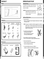
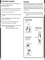
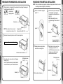
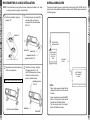
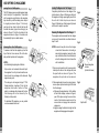
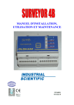
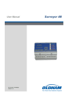
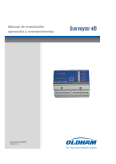
OWNER’S MANUAL
AND
INSTALLATION GUIDE
ACC56M
10-DISC CD CHANGER
Visit us at www.asaelectronics.com to see our full line of mobile audio and video products.
MADE IN CHINA
INTRODUCTION
Congratulations on your purchase of the AQUATRONICS ACC56M REMOTE-CONTROL
10-DISC CD CHANGER.
This system allows you to easily upgrade your existing audio system to include a quality CD
entertainment function. Best of all, the CD Changer is easy to install. There is only one cable to
plug in to the rear of the already equipped radio. Just follow the simple step-by-step instructions
that follow.
FEATURES
■ Remote mount changer holds up to 10 compact discs.
■ Advanced technology includes 8x oversampling digital filter and twin1-bit digital/analog
converters
■ The special design allows horizontal, vertical or 45-degree mounting.
■ Designed to work with Aquatronics and Voyager CDC ready radios.
INDEX
Introduction and Contents
page 1
Hints for Correct and Safe Operation
page 10
Packing List
page 2
Handling the Discs
page 11
Before Installing the Unit Page
page 3
Use of the CD Magazine
page 12
Where to Install the Changer
page 4
Specifications
page 14
Installation
page 5
Troubleshooting
page 15
Overall Wiring View
page 9
1
PACKING LIST
BEFORE INSTALLING THE UNIT
Main Unit
Transport Lock Screws
The mechanism in the CD changer is "locked" into place during
shipment by three transport lock screws. Be sure to remove the
screws prior to installation.
REAR
CAUTION: After removing the transport lock screws, place the
supplied seals (A) over the screw holes. These
seals are used to keep dust out of the unit, which
could cause a malfunction.
BOTTOM
FRONT
TRANSPORT LOCK SCREWS
(2 RIGHT SIDE,1 LEFT SIDE)
lnstallation and Wiring Precautions
1. To prevent a short-circuit,
● Be sure to turn off the ignition and remove the negative (-) battery cable, prior to installation.
● Connect power wires last.
Installation Parts
Bracket(L)
Bracket(R)
Hexagonal bolt
with washer (M5 x 10)
Screw (C) phillips
Head Self-Tapping Screw
(T3 x12)
4pcs.
2pcs.
1pc.
1pc.
5Meter Din Cable
Self-tapping screw
(T5 x12)
4pcs.
1pc.
Seals(A)
Seals(B)
1pc.
1pc.
2. Do not install the unit in the following locations.
● Locations exposed to direct sunlight.
● Where hot air is discharged from the car heater.
● In areas subject to extreme temperatures.
3. Incorrect installation can cause the disc to skip when playing.
Be sure to mount the unit firmly in place, using the supplied brackets and screws.
4.
Other Accessories
CD Magazine(P/N 10CD56M)
NOTE: If the changer is to be installed in a vehicle that is equipped with an on-board drive or
navigation computer, do not disconnect the battery cable. If the cable is disconnected,
5 the computer memory may be lost. Under these conditions, use extra caution during
installation not to cause a short circuit.
Be sure to use the supplied screws.
Be careful not to snag any wires when tightening screws.
● Be careful not to damage the vehicle wiring.
●
●
lndex label sheet
Owner’s Manual
and lnstallation Guide
OWNER’S MANUAL
AND
INSTALLATION GUIDE
5.
●
This unit cannot be installed on its side, end, or upside down.
Installation in such positions will cause malfunctioning of the mechanism.
ACC56M
10-DISC CD CHANGER
1pc.
2
1pc.
1pc.
3
WHERE TO INSTALL THE CHANGER
INSTALLATION
A few of the many mounting possibilities are shown below. The following precautions must
be considered when selecting the mounting location.
Installation Cautions and Warnings:
The ACC56M changer is designed for horizontal (flat), vertical (upright) or 45-degree
mounting. It must never be mounted upside-down or on either one of it's sides as explained
previously. The position of the built-in anti-vibration springs (left and right side), must
correspond to the mounting position chosen. If the springs are not set correctly for the type
of installation chosen, the anti-vibration compensation will not be effective and vibration
may cause the disc to skip.
1.Fuel Tank - WARNING! Never install above your fuel tank as the holes you must drill may
pierce the tank or the fuel lines. Also check for other obstructions such as wires, etc.
2.Excessive Heat - Avoid areas exposed to direct sunlight.
3.Ease of Use - Make certain the changer is easily accessible for loading and unloading the
CD magazine.
4.Distance - The data cable that joins the changer to your existing CDC ready radio is
15 feet long. Do not exceed this length.
5.If mounting to a plastic surface, do not use the self-tapping screws provided.
Use the bolts and hex nuts provided for a more secure installation.
CAUTION: After setting the built-in anti-vibration springs, place the supplied Seals (B) over
the holes. These seals are used to keep dust, which could cause a malfunction,
out of the unit.
HORZONTAL INSTALLATION
Set the 4 anti-vibration springs
to position“H”
position“H”
IMPORTANT: Failure to properly secure the CD changer is the most common cause of
“skipping” and related CD play problems.
Changer must be mounted as explained on the following pages.
VERTICAL INSTALLATION
Set the 4 anti-vibration springs
to position“V”
45°ANGLE INSTALLATION
Set the 4 anti-vibration
springs to position“45°”
position“V”
position“45°”
4
5
PROCEDURE FOR HORIZONTAL INSTALLATION
Attach bracket (L) and bracket (R) to each side of the unit,using the hexagonal
bolts with washer base (M5 x 10).
Anti-vibration
springs position
PROCEDURE FOR VERTICAL INSTALLATION
NOTE: If the anti-vibration spring position has been changed and verified for vertical
mounting (as shown on page 6), start with step 2.
Set the 4 anti-vibration springs to
position “v”
NOTE: Use seals(A) to cover
unused mounting holes on sides of
unit.
Bracket (L)
Bracket (R)
Hexagonal bolt
with washer base (M5 x 10)
NOTE: Use seals (A) to cover unused
mounting holes on sides of unit.
Attach bracket (L) and bracket (R) to
each side of the unit, using the
hexagonal bolts with washer base
(M5 x 10).
position “v”
Bracket (L)
Determine the mounting location, and drill four mounting holes.
Bracket (R)
Hexagonal bolt with
washer base (M5 x 10)
Never mount the unit near the fuel tank.
Determine the mounting location,
and drill four mounting holes.
Drill holes 4mm in diameter.
Secure the unit in place,using four self-tapping
screws(T5x12).
Use RTV(sillicone sealer)on screw threads or
around the holes to prevent moisture intrusion.
Mount the unit in place, using four
self-tapping screws (T5 x 12).
Use RTV(silicone sealer) on screw
threads or around the holes to
prevent moisture intrusion.
Self-tapping screw
(T5 x 12)
Self-tapping screw
(T5 x 12)
Bracket (L)
Bracket (L)
Drill holes 4mm in diameter.
Bracket (R)
Bracket (R)
6
7
PROCEDURE FOR 45°ANGLE INSTALLATION
OVERALL WIRING VIEW
NOTE: If the anti-vibration spring position has been changed and verified for 45°angle
mounting (as shown on page 6), start with step 2.
Set the 4 anti-vibration springs to
position “45°”
This page is provided to give you a quick look at the entire wiring of the ACC56M. Use it to
plan your wire routing paths and possible connection points. Detailed wiring is explained in
the following pages.
Attach bracket (L) and bracket (R) to
each side of the unit,using the
hexagonal bolts with washer base
(M5 x 10).
position“45°
”
EXISTING RADIO
ANTENNA SOCKET
Bracket (L)
Bracket (R)
AQUATRONICS
OR VOYAGER
CDC READY
RADIO
Hexagonal bolt with
washer base (M5 x 10)
Determine the mounting location,and
drill four mounting holes.
Mount the unit in place, using four
self-tapping screws (T5 x 12).
Use RTV(silicone sealer) on screw
threads or around the holes to
prevent moisture intrusion.
Never mount the unit near the fuel tank.
Self-tapping screw
(T5 x 12)
10-DISC COMPACT
DISC CHANGER
ACC56M
NOTES:
● When routing wires and cables from the
changer to the radio, it is best to conceal
the wires.
●
Drill holes 4mm in diameter.
8
DATA CABLE
(15 FEET)
Bracket (L)
It may be necessary to press the RESET
button on the face of the radio the first
time after the ACC56M is lnstalled.
This will causethe radio to “recognize”
that the ACC56M is connected.
Bracket (R)
9
HINTS FOR CORRECT AND SAFE OPERATION
This CD Changer is designed to be operated only on 12 volt DC negative ground systems.
The unit cannot be used on 24 volt or positive ground systems.
Temperature
The unit may not operate correctly in extremely hot or cold temperatures. It is equipped
with a built-in thermal protection circuit which will stop operation of the unit when the
temperature reaches the preset level. If this should happen, the unit will resume operation
when the vehicle returns to a normal temperature range. Remove the magazine from the
unit when it is not being used during hot weather. If the CD changer is not used for long
periods of time, remove the compact discs from the magazine, and store them in their
cases.
Condensation
Moisture can condense on the laser lens of the CD changer during rainy and humid days, If
this should happen the unit will not operate correctly. To remedy the situation, remove the
discs from the unit and wait approximately one hour. During this time the moisture will
evaporate and the unit will operate normally.
Interruptions in sound(Skipping)
The sound from the unit may "skip" and be interrupted if the anti-vibration springs are not
set correctly, if the changer is mounted on-end or upside-down, or when travelling on very
rough surfaces. If this should occur, check for errors made during installation or wait for the
surface to improve.
3’’(8 cm) CD-Singles
This unit is not designed to play 3" (8cm) CD-Single discs. Inserting a 3" disc into the
magazine, either with or without a 3" disc adaptor, can damage the changer and the disc.
Such damage will not be covered by the Warranty on this product.
10
HANDLING THE DISCS
Dirt, dust, scratches and warpage cause sound skips during playback and a deterioration of
sound quality. To take proper care of your discs:
1.Use compact discs that have the
logo.
2.Fingerprints and dust should be carefully wiped off the disc's signal surface(glossy
side)with a soft cloth. Unlike conventional records, the compact disc has no grooves to
collect dust and microscopic debris, so gently wiping with a soft cloth should remove most
particles. Wipe in a straight motion from the inside to the outside of the disc. Small dust
particles or light stains will have absolutely no effect on reproduction quality.
3.Never use such chemicals as record sprays, antistatic sprays or fluids, benzine or
thinner to clean compact discs. Such chemicals could irreparably damage the disc's
plastic surface.
4.Discs should be put back in their cases after use to avoid serious scratches that could
cause the sound to skip.
5.Do not expose discs to direct sunlight, high humidity, or high temperatures for extended
periods of time. Long exposure to high temperatures can warp the disc.
6.Do not stick paper, labels, or tape on the disc surface.
7.Do not write with any type of pen, pencil, or marker on the disc surface.
8.To minimize fingerprints and smudges on the signal surface, always try to hold the discs
by their outer edge and center hole.
11
USE OF THE CD MAGAZINE
Loading Disc Into The Magazine
Fig. 1
Completely slide the door on the changer to the
right as shown in Figure 4. Making sure the top of
the magazine is facing upward,gently insert it into
the unit until it clicks into place, as shown in
Figure 5. Slide the door of the changer fully closed
and the unit is ready for operation.
This CD Changer uses a specially-designed maga
zine to hold up to 10 compact discs. To load discs
into the magazine, grip the tab on the magazine
tray into which you will be loading a disc and pull
it out gently as shown in Figure 1. Pull out only
one tray at a time. Insert a disc into the tray with
the label side down (play surface facing up) as
shown in Figure 2. Push the tray back into the
magazine as shown in Figure 3. Load discs into
the remaining 9 trays in a similar manner.
Removing Discs From The Magazine
NOTES :
● Avoid touching the playing side of the disc.
12
●
This changer is not designed to play 3" CD-5
Single discs(8cm). Inserting a 3" disc into the
magazine, either with or without a 3"disc
adaptor, can damage the changer and the disc.
Such damage will not be covered by the
Warranty on this product.
●
For additional CD magazines, you may contact
us at www.asaelectronics.com
The magazine can be removed from the changer
using one of two methods as outlined below in
steps 1 and 2.
Fig. 5
NOTE: Be sure to keep the door on the changer
closed at all times when not loading or
removing the magazine. Leaving the door
open could allow dust, dirt and moisture to
enter the changer which could cause the
unit to malfunction.
To remove a disc from the magazine, pull out the
tray of the disc to be removed, lift out the disc,
and push the tray back into the magazine.
Only one disc can be inserted into each tray of
the magazine. Do not try to insert more than one
disc into each tray as damage to the discs and
magazine may occur.
Fig. 4
Removing The Magazine From The Changer
Fig. 2
●
Loading The Magazine Into The Changer
Fig. 3
Manual magazine
release
(bottom left corner)
1.During normal operation with power applied,
slide open the door on the changer and press
the eject button as shown in Figure 6. The
magazine will eject and can be removed.
2. If the magazinewill not ejectin a normal manner,
remove power by disconnecting the DIN cable
from the changer.
a. Slide open the magazine door. On the bottom
left rear of the changer, as shown in Figure 5,
peel off the tape covering the access hole;
insert a thin-bladed screwdriver into the
access hole and engage the mechanical
release arm.
b. Lightly leverage the blade to the right and the
magazine will disengage and be ejected.
Fig. 6
Eject button
13
TROUBLESHOOTING
SPECIFICATIONS
Changer
Frequency Response ……………………………………………………… 5 - 20,000 Hz ±1dB
Distortion ……………………………………………………………………… 0.008% @ 1kHz
An error made in operation or during installation of this product may be mistaken for a
system malfunction. Please perform the checks described below before contacting your
dealer or service facility.
Symptom
Possible Cause
Dynamic Range …………………………………………………………………………… 95 dB
Blown fuse
Check fuses in vehicle fuse box and
changer system.
Replace as necessary with fuse of
same type and rating as original. If
fuse blows again, consult with
service facility.
lncorrect connection
Check all wiring and correct as
necessary.
Magazine cannot be
installed
Magazine is inserted in wrong
direction.
Insert magazine in proper direction.
CD is not played
Disc is located incorrectly in
magazine
Load disc correctly in the magazine.
Scratches on disc or warped disc
Check sound on another disc. If
sound from second disc is OK, first
disc is defective.
Extremely dirty disc
Clean disc
Transit screws still in place
Remove the transit screws from
sides of the unit.
Mounting angle adjustment is not
correct.
Set the mounting angle adjustment
to the correct position as per the
installation instructions.
Signal-to-Noise Ratio ……………………………………………………………………… 95 dB
Channel Separation……………………………………………………………… 70 dB @ 1kHz
Wow & Flutter ………………………………………………………… below measurable limits
No power
Dimensions …………………………………………………(W) 9-6/8" x (H) 3-2/8" x(D) 7-1/8"
(W)250 mm x (H)81 mm x (D)181 mm
Operating Voltage ……………………………………………… 12 Volts DC, negative ground
Current Drain
…………………………………………… 800mA (Playback/loading/ejecting)
Accessories Supplied: …………………………………… 10-disc magazine, P/N 10CD56M
Remedy
Mounting hardware (1set)
Connecting cable (1ea.)
Noise,Skipping,or
intermittent sound
during playback
Radio will not switch
to CDC mode
14
Radio has not been initialized Press the RESET button on the face
with the ACC56M attached
of the radio.
15
16