1
User Manual
Surveyor 4B
Part Number: NPS4BGB
Version: C.2
The Fixed Gas Detection Experts
GAS DETECTION
We are delighted that you have chosen an OLDHAM instrument and would like to thank you for your
choice.
We have taken all the necessary measures to ensure that your instrument provides total satisfaction in the
future.
Now it is important to read this document carefully.
EXTENT OF RESPONSIBILITY
* OLDHAM declines its responsibility towards any person for material damage, physical injury or death resulting
wholly or partly from inappropriate use, installation or storage of its equipment resulting from failure to observe
instructions and warnings and/or standards and regulations in force.
* OLDHAM neither supports nor authorises any company, physical or moral person to assume responsibility on
behalf of OLDHAM, even if it is involved in the sale of OLDHAM products.
* OLDHAM cannot be held responsible for direct or indirect damage or be required to pay direct or indirect
compensation resulting from the sale or use of any of its products IF THESE PRODUCTS HAVE NOT BEEN
DEFINED AND CHOSEN BY OLDHAM FOR THEIR SPECIFIC USE.
CLAUSES CONCERNING PROPERTY
* Drawings, plans, specifications and information included in this document contain confidential information that is
the property of OLDHAM.
* None of this information may be reproduced, copied, divulged or translated, by physical, electronic or any other
means, nor used as the basis for the manufacture or sale of OLDHAM equipment or for any other reasons without
prior consent from OLDHAM.
WARNINGS
* This document is not contractually binding. In the interests of its customers, OLDHAM reserves to modify the
technical specifications of its equipment without notice, in order to improve its performance.
* READ THIS MANUAL CAREFULLY BEFORE FIRST USE OF THE EQUIPMENT: this manual must be
read by any person who is or will be responsible for using, maintaining or repairing this equipment.
* This equipment will only provide the announced performance levels if it is used, maintained and repaired
according to OLDHAM directives, by OLDHAM personnel or by personnel approved by OLDHAM.
GUARANTEE
2 years guarantee in normal conditions of use on parts and technical labour, return in our workshops, excluding
consumables (sensors, filters, etc.).
3
Warnings
This manual must be read carefully before installing and starting up and, in particular, care
must be taken to observe the points concerning the safety of the equipment for intermediate
or end users.
Installation must be performed and electrical connections made by qualified personnel in
accordance with the manufacturer's instructions and with the standards specified by the
relevant authorities.
Failure to comply with instructions can have serious consequences for the safety of
personnel. An absolutely rigorous approach is required, especially as concerns electricity
and fitting (connections and connection to the power network).
Any modification of the equipment or the use of parts not specified as original
manufacturer's parts could lead to the cancellation of any form of warranty.
The data logger is intended to be used for one or more applications specified in the technical
characteristics.
The values indicated must not be exceeded in any circumstances.
This is not a contractually binding document. In the interest of its customers, OLDHAM
reserves the right to make any changes, without notice, to the technical characteristics of its
equipment in order to improve performance levels.
Warning signs
Protective earth terminal
Caution: risk of electric shocks
Caution (See accompanying documents)
4
Contents
I. DESCRIPTION
7
II. MOUNTING OF THE SURVEYOR 4B
7
III. CONNECTIONS
9
3.1. Alternative power supply
9
3.2. DC power supply
9
3.3. Explosimetric detectors
10
3.4. External components
10
3.5. Examples of installation
11
IV. OPERATING INSTRUCTIONS
12
4.1. Switching on
13
4.2. Switching off
13
4.3. Alarms
13
4.3.1. GAS alarm
4.3.2. FAULT alarms
13
14
4.4. Adjustments
14
4.4.1. Adjusting the "gas alarm" thresholds
4.4.2. Acknowledgement of gas alarms
4.4.3. Adjusting the ZERO
4.4.4. Checking the sensitivity
15
16
17
17
4.5. Replacing the fuse
19
V. TECHNICAL SPECIFICATIONS
21
VI. DISPOSAL
21
VII. EC DECLARATION OF CONFORMITY
22
5
6
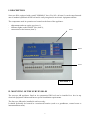
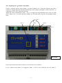
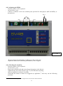
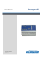
I. DESCRIPTION
Surveyor 4B is equipped with a small "NORMAL" box (58 x 105 x 90 mm). It can be snap-fastened
onto a standard symmetrical DIN rail and is easily integrated in an electric equipment cabinet.
The components used in operation are located on the front of the appliance:
-
adjustments and tests on the top (item 1),
indicator lights on the FRONT face (item 2),
connections at the bottom (item 3).
Item 1
Item 2
Item 3
FIGURE 1
II. MOUNTING OF THE SURVEYOR 4B
The surveyor 4B appliance fitted on its symmetrical DIN rail can be installed in a box in any
electrical equipment cabinet and has no special installation requirements.
The Surveyor 4B can be installed in safe area only.
It should preferably be located in a monitored location (such as a guardhouse, control room or
instrumentation room).
7
8
III. CONNECTIONS
Electrical connections must be made by a specialist and must comply with the regulations in force.
They must also be in conformance with standard NF C 15-100.
The nature of the current and line voltage must be checked. The line voltage must match the voltage
specified on the plate fitted on the Surveyor 4B. The voltage is configured in the factory.
The wires to be connected to the Surveyor 4B must have a minimum cross section of 1.5 mm².
The Surveyor 4B appliance can be supplied with either 230 VAC 1 or 12 VCC 2.
3.1. Alternative power supply
230 volt AC power supply
The Surveyor 4B must be protected on the upstream side by a two-pole earth leakage circuit breaker
(1A).
The response curve must be of type D.
The mains power supply must be wired on the two points marked N (Neutral) and P (Phase) on the
Surveyor 4B terminal block (see Fig 2, item 1).
Power consumption: 5 VA max. (detector connected).
3.2. DC power supply
12-volt power supply
The 12 volt power supply can be connected to the points marked 0 and 12 V on the Surveyor 4B
terminal block (see Fig. 2, item 2).
The cable must have a minimum cross section of 1.5 mm².
Power consumption: 4 W max. (detector connected).
Item 1
1
2
Item 2
From 207 to 242 V AC
From 11.5 to 14 V DC
9
FIGURE 2
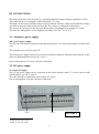
3.3. Explosimetric detectors
Only explosimetric detectors of the "bridge" type can be connected to the SV 4B.
Surveyor 4B and the detector are connected together by a shielded cable with three active
conductors. The shielded cable is to be connected to the earth at one end only.
Terminals C1, C2 and C3 of Surveyor 4B and the detector are to be connected in opposite mode
(see Fig. 3).
Detector terminal
FIGURE 3
3
2
1
The maximum loop resistance is 1.4 ohms.
For example: the maximum distance between Surveyor 4B and the detector will be 40 m with
conductors with a cross section of 1.5 mm².
3.4. External components
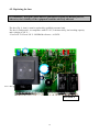
Surveyor 4B is equipped with the following two relays.
Relay 1 (REL 1), which is in mode, corresponds to the first gas alarm threshold and to the
"FAULT" alarm.
This relay is equipped with SPDT contacts available on the SV 4B terminal block (item 3, Fig.
5).
Relay 2 (REL 2), which is "negative safety" mode, corresponds to the second gas threshold
only. This relay is also equipped with SPDT contacts available on the SV 4B terminal block
(item 4, Fig. 5).
These both relays could be configured in positive and negative security (programmation by
welding slots on the printed circuit board: made only by OLDHAM or a skilled personal).
FIGURE 5
Item 3
Item 4
NB: The relay contacts are dry contacts, corresponding to the appliance without power supply.
Caution: The high-power solenoid valves cannot be directly remote controlled 3. A power relay is
required.
3
The maximum current through the relay contacts will be 2 A and the maximum voltage will be
240 V ~ or 60 V - - -.
10
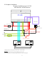
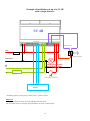
3.5. Examples of installation
Example of installation set up of a SV 4B
with TWO OLC 10 TWIN detectors
SV 4B
C1 C2 C3
Telephone dialer
Fuse or circuit breaker
Life (L)
To a phone network line
NEUTRAL (N)
Closed solenoid valve status display lignt
0
12 VCC
+
Fuse
Gas valve closed *
123
123
Detector
OLC twin1
OUT
IN
Detector
OLC twin 2
OUT
IN
* Breaking capacity of rating relays switch contact : 120VA ou 30W
Important:
The relay's contacts are shown on the SV 4B label, unit switch off.
The AL1/ DEF relays are normally energized and the AL2 relay is unenergized.
11
Example of installation set up of a SV 4B
with a single detector.
SV 4B
C1 C2 C3
Telephone dialer
LIFE
Fuse or circuit breaker
To a phone netwok line
NEUTRAL
Closed solenoid valve
status display lignt
0
+
Fuse
Gas valve closed *
1
2
3
Detector
* Breaking capacity of rating relays switch contact : 120VA ou 30W
Important:
The relay's contacts are shown on the SV 4B label, unit switch off.
The AL1/ DEF relays are normally energized and the AL2 relay is unenergized.
12
IV. OPERATING INSTRUCTIONS
4.1. Switching on
It is assumed that all the necessary connections have been made and that the whole installation
complies with the standards currently in force.
As soon as the SV 4B is supplied with power, it is ready to use and the GREEN light-emitting diode
lights up (item 1, Fig. 6).
Relay 1 is operated ("positive safety" position).
4.2. Switching off
The SV 4B is switched off by cutting off the power supply on an electrical equipment cabinet.
4.3. Alarms
4.3.1. GAS alarm
The SV 4B has two adjustable GAS alarm thresholds but the second threshold (AL 2) must be twice
the first (AL 1).
Therefore, the red light-emitting diodes "AL1" and "AL2" (item 3, Fig. 6) come on as soon as the
alarm thresholds are exceeded (time delay of 7 seconds): LED flashing. The audio alarm (buzzer) is
activated and the corresponding relays are tripped.
Item 1
Item 2
Item 3
FIGURE 6
13
4.3.2. FAULT alarms
The SV 4B is equipped with a fault alarm (visual alarm (item 2, Fig. 6), audio alarm and relay 1)
which is activated in the following cases:
One or more wires of the telemetry line interrupted,
One or more wires of the telemetry line short-circuited or with excessive power consumption.
NB: The ALARM LEDs may also be activated depending on the circumstances of the
interruption or the short circuit.
4.4. Adjustments
Caution: The operations and adjustments described in this chapter must be performed by authorized
personnel only as they can affect the appliance's reliability in detection.
Gas detection instruments are potential life-saving devices. Recognizing this fact, OLDHAM
Corporation recommends that a functional “bump” test be performed on every fixed gas-monitoring
instruments as part of a regular maintenance program. A functional test is defined as a brief
exposure of the detector to a concentration of gas(es) in excess of the lowest alarm set-point for
each sensor for the purpose of verifying sensor and alarm operation and is not intended to be a
measure of the accuracy of the instrument.
OLDHAM further recommends that a full instrument calibration be performed using a certified
concentration(s) of calibration gas(es) quarterly, every 3 months.* Calibrations may be necessary
more or less frequently based, for example, on application, field conditions, exposure to gas, sensor
technology, and environmental conditions. The frequency of calibration is best determined by
company policy or local regulatory agencies.
If an instrument fails to operate properly during any functional “bump” test, a full instrument
calibration should be performed successfully prior to use.
These recommendations are based on safe work procedures, industry best practises, and regulatory
standards to ensure worker safety. OLDHAM is not responsible for setting safety practices and
policies.
* For new installations it may be prudent to carry out bump tests frequently at first (perhaps
weekly), increasing the time intervals (to, perhaps, monthly or more) as confidence grows with
experience in the installation concerned, on the basis of the maintenance record.
14
4.4.1. Adjusting the "gas alarm" thresholds
Using a "reference gas kit" (gas cylinder + pressure regulator, etc.), inject the reference gas with a
content level higher than the first threshold desired. (For example, threshold 1 will be 20% LEL, so
a minimum of 25% LEL should be injected).
Adjust the alarm potentiometer (item 1, Fig. 7) to trigger the first threshold (AL1): the red LED
(AL1) flashes (for 7 seconds) and then remains on in steady mode, trip the corresponding alarm
relay.
MV
item 5
item 3
item 1
item 2
item 4
FIGURE 7
If you stop at this point, alarm 2 will be set to twice the level of alarm 1.
If you continue until alarm 2 is triggered: alarm 1 will be set to half the level of alarm 2.
15
If you wish to lock the alarm relays (inhibiting the relays) during these alarm threshold adjustments:
set the maintenance switch to the high position (item 2, Fig. 7).
(
Up )
Maintenance
Normal
Caution: When the adjustments have been made, do not forget to place the switch back in its
normal position.
Terminal posts (item 3, Fig. 7) are used to connect up a voltmeter for the reading of a signal (in
mV) corresponding to the content level of the injected gas.
Then, using a rule of three, it is possible to calculate and adjust another signal (in mV) for an alarm
threshold (potentiometer: item 1, Fig. 7) corresponding to a different gas content level.
For example: when you inject 1% methane, you read 1,000 mV (for instance).
If you set the alarm potentiometer to read 1,500 mV, the alarm is triggered at 1.5%
methane.
Signal =
1000mVx1%
1500mV
1000mV
Or
Threshold (%) =
1% x1500mV
15%
.
1000mV
4.4.2. Acknowledgement of gas alarms
A switch (item 4, Fig. 7) is used to acknowledge gas alarms in manual mode4 or automatic mode 5.
(
Automatic ack.
Up )
Manual ack.
Remark: As long as there is a high enough concentration of gas to trigger an alarm, it is
impossible to clear that alarm manually (with the Ack. button).
4
Manual mode: When a gas alarm is triggered, it must be cleared manually even if the content level has fallen to zero
(or to below the threshold). This is done by pressing the Ack. key (item 5, Fig. 7).
5
Automatic mode: When a gas alarm is triggered, it is cleared automatically as soon as the content level falls below the
alarm threshold.
16
4.4.3. Adjusting the ZERO
- Necessary when a cell is replaced.
- At least twice a year.
- Connect a voltmeter to the two terminal posts provided for that purpose (MF and MES), as
shown below.
Rep 3
MV
Rep 1
Rep 2
FIGURE 8
-
Be sure to be in pure atmosphere (without gas) (If not, inject air)
Adjust the ZERO (0 mV) with the potentiometer, item 1.Figure8
4.4.4. Checking the sensitivity
- Necessary when a cell is replaced.
- At least twice a year.
- Prepare the calibration kit and secure the gas input pipe to the detector.
- Adjust the flow rate of the reference gas 6(1) to 60 l/h before injecting.
- Allow to stabilize for at least 10 seconds.
- Check that the alarm or alarms are triggered (as applicable 6) and carry out the following
procedure.
6
The value of the reference gas must be higher than at least the first alarm threshold.
17
Inject
reference gas
with content
> threshold
AL1
YES
Alarm 1
triggered?
YES
NO
Cell sensitivity is satisfactory
Cell sensitivity is inadequate
Can AL 1 be
triggered by
adjusting the
alarm
potentiometer
(item 2, Fig. 8)?
YES
NO
Cell sensitivity is now satisfactory.
18
Cell sensitivity is inadequate:
replace the cell and repeat
calibration (O/S).
4.5. Replacing the fuse
It is mandatory that spare parts must be guaranteed original OLDHAM parts as,
otherwise, the reliability of the equipment could be adversely affected.
The fuse (Fig. 9, item 1) must be replaced by qualified personnel only.
The fuse is, and must be, in compliance with CEI 127, with time-delay, low breaking capacity
and a voltage of 250 V ~.
- Fuse 5x20- T125 mA 250 V- OLDHAM reference = 6154701
Item 1
FIGURE 9
19
20
V. TECHNICAL SPECIFICATIONS
Manufacturer
Type
Function
Capacity
Measurement
Measurement
Display unit
Visual alarms
Audio alarm
Alarm Acknowledgement
Electric power supplies
AC
DC
Power consumption
Electrical protection
Relays
Relay 1
Relay 2
Contact
Max. breaking capacity
Maximum voltage
Maximum current
Measuring line
Cable
Maximum line length
Maximum loop resistance
Mounting
Miscellaneous
Technology
Mains visual indicator
Housing
Warranty
Dimensions
Weight
Cable inlets/outlets
Ingress Protection
Operating conditions
Ambient temperature
Relative humidity
Noise level
OLDHAM
SURVEYOR 4B
Control station for explosive gas detectors
1 channel: 1 or 2 detectors
Continuous
None
Failure: yellow
Gas, 1st threshold: red
Gas, 2nd threshold: red
Integrated
Manual or automatic
230 VAC (207 to 242 V) (programmed in factory)
12 VDC (11.5 to 14 V)
5 VA or 4 W (detector connected)
Fuse
Common to gas and fault
Gas
SPDT, relay 1 (positive safety)
SPDT, relay 2
60 VA or 28 W resistive
240 VAC or 60 VDC
1A
3 conductors
40 m (with conductor 1.5 mm²)
1.4 ohms
On symmetrical DIN rail
SMC (surface mounted component)
Green LED
NORYL
1 year
58 x 105 x 90 mm
0.360 kg
Screw type terminal block
IP 30
-10°C to +45°C
5% to 95% non-condensed
Not significant
VI. DISPOSAL
Concerning the conservation, of the protection and the improvement of the
quality of the environment, as well as for the protection of the health of the
persons and the careful and rational use of natural resources, SV 4B has to be the
object of a selective collection for the electronic equipments and cannot be
scrapped with the normal domestic waste. The user thus has the obligation to
separate the SV 4B of the other waste so as to guarantee that it is recycled in a
sure way at the environmental level. For more details of the existing sites of
collection, contact the local administration or the distributor of this product.
21
VII. EC DECLARATION OF CONFORMITY
22
23
.
The Fixed Gas Detection Experts
EUROPEAN PLANT AND OFFICES
Z.I. Est – rue Orfila CS 20417 – 62027 Arras Cedex FRANCE
Tél: +33 (0)3 21 60 80 80 – Fax: +33 (0)3 21 60 80 00
Website: http://www.oldhamgas.com
AMERICAS
Tel: +1-713-559-9280
Fax: +1-281-292-2860
[email protected]
ASIA PACIFIC
Tel: +86-21-3127-6373
Fax: +86-21-3127-6365
[email protected]
EUROPE
Tel: +33-321-608-080
Fax: +33-321-608-000
[email protected]