1
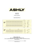
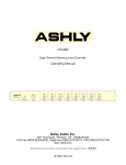
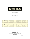
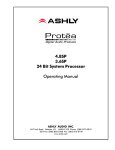
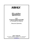
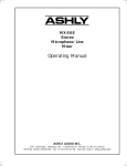
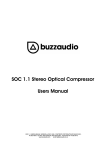
MX-206
Stereo Microphone Mixer
Operating Manual
Ashly Audio Inc.
847 Holt Road, Webster, NY 14580-9103
Toll Free (800) 828-6308, Telephone (585) 872-0010, FAX (585) 872-0739
www.ashly.com
All Trademarks referred to herein, are the property of their respective owners. R-042707
All Rights Reserved
Page - 2
Operator Manual – MX-206 Mixer
This page intentionally left blank
Copyright© 2006 – Ashly Audio Inc.
Operator Manual – MX-206 Mixer
Page - 3
Important Safety Instructions
Consignes de sécurité à lire attentivement
Safety Instructions – 3
Introduction - 4
MX-206 Mixer – 5
Connectors & Cables – 5
Physical Description - 6
Installation – 7
Typical Applications - 8
The lightning flash with arrowhead symbol, within an equilateral triangle, is
intended to alert the user to the presence of uninsulated "dangerous voltage"
within the product's enclosure that may be of sufficient magnitude to constitute a
risk of electric shock to persons. The exclamation point within an equilateral
triangle is intended to alert the user to the presence of important operating and
maintenance instructions in the literature accompanying the device.
1.
2.
3.
4.
5.
6.
7.
8.
9.
10.
11.
12.
13.
14.
15.
Read these instructions.
Keep these instructions.
Heed all warnings.
Follow all instructions.
To reduce the risk of fire or electric shock, do not expose
this apparatus to rain or moisture.
Do not use this apparatus near water.
Clean only with dry cloth.
Do not block any ventilation openings. Install in
accordance with the manufacturer’s instructions.
Do not install near any heat sources such as radiators, heat
registers, stoves, or other apparatus (including amplifiers)
that produce heat.
Do not defeat the safety purpose of the polarized or
grounding-type plug. A polarized plug has two blades
with one wider than the other. A grounding type plug has
two blades and a third grounding prong. The wide blade
or the third prong are provided for your safety. If the
provided plug does not fit into your outlet, consult an
electrician for replacement of the obsolete outlet.
Protect the power cord from being walked on or pinched
particularly at plugs, convenience receptacles, and the
point where they exit from the apparatus.
Only use attachments/accessories specified by the
manufacturer.
Use only with the cart, stand, tripod, bracket, or table
specified by the manufacturer, or sold with the
apparatus. When a cart is used, use caution when
moving the cart/apparatus combination to avoid injury
from tip-over.
Unplug this apparatus during lightning storms or when
unused for long periods of time.
Refer all servicing to qualified service personnel.
Servicing is required when the apparatus has been
damaged in any way, such as power-supply cord or plug
is damaged, liquid has been spilled or objects have fallen
into the apparatus, the apparatus has been exposed to
rain or moisture, does not operate normally, or has been
dropped.
Le symbole de la flèche dans un triangle équilateral symbolisant la foudre est
prévu pour sensibiliser l’utilisateur à la présence de tension de voltage non isolée
à l’intérieur de l’appareil. Elle pourrait constituer un danger de risque de
décharge électrique pour les utilisateurs. Le point d’exclamation dans le triangle
équilatérale alerte l’utilisateur de la présence de consignes qu’il doit d’abord
consulter avant d’utiliser l’appareil.
1.
2.
3.
4.
5.
6.
7.
8.
9.
10.
11.
12.
13.
14.
15.
Lisez ces instructions.
Conservez ces instructions.
Observez les avertissements.
Suivez ces instructions.
Pour réduire le risque de feu ou la décharge électrique,
ne pas exposer cet appareil pour pleuvoir ou l'humidité.
Ne pas utiliser l’appareil près de l’eau.
Le nettoyer à l’aide d’un tissus sec.
Ne pas bloquer les ouvertures de ventilation, installer
selon les consignes du fabricant.
Eloigner des sources de chaleur tel: radiateurs,
fourneaux ou autres appareils qui produisent de la
chaleur.
Ne pas modifier ou amputer le système de la mise à
terre. Une prise avec mise à terre comprend deux lames
dont une plus large ainsi qu’une mise à terre: ne pas la
couper ou la modifier. Si la prise murale n’accepte pas
la fiche, consulter un électricien pour qu’il remplace la
prise désuète.
Protéger le cordon de secteur contre tous bris ou
pincement qui pourraient l’endommager, soit à la fiche
murale ou à l’appareil.
N’employer que les accessoires recommandés par le
fabricant.
N’utiliser qu’avec les systèmes de fixation,chariots,
trépied ou autres, approuvés par le fabricant ou vendus
avec l’appareil.
Débrancher l’appareil lors des orages électriques ou si
inutilisé pendant une longue période de temps.
Un entretient effectué par un centre de service accrédité
est exigé si l’appareil a été endommagé de quelque
façon: si il a été exposé à la pluie,, l’humidité ou s’il ne
fonctionne pas normalement ou qu’il a été échappé.
All Rights Reserved
Troubleshooting - 9
Dimensions - 9
Specifications - 10
Warranty - 11
This manual uses a
Perpetual Table Of
Contents. Each page
has a copy of the
manual’s contents in a
gray box just like this
one. The section you are
in will always be bold
with the other sections
“grayed out.” The feature
allows you to jump
directly to another
section without having to
return to a Table Of
Contents page.
Page - 4
Operator Manual – MX-206 Mixer
Safety Instructions – 3
Introduction - 4
MX-206 Mixer – 5
Connectors & Cables – 5
Physical Description - 6
Installation – 7
Typical Applications - 8
Troubleshooting - 9
Dimensions - 9
Specifications - 10
Warranty - 11
Introduction
Congratulations on your purchase of an Ashly MX-206 stereo mixer. In one compact rackmount package we have combined features, reliability, and sonic performance you have
come to expect from Ashly. Features of this unit include:
20dB input pad on each channel
Up to 60dB of mic preamp gain
Switchable +48V phantom power
Concentric level and pan control on each channel
Ultra low-noise summing amplifiers
Two 5-segment LED arrays
Stereo line level outputs on 1/4" connectors
Tape/CD inputs and outputs on RCA connectors
Transformer isolated 600 ohm outputs on XLR connectors
Professional quality 16mm metal shaft potentiometers on all controls
About Ashly
Ashly Audio was founded in 1974 by a group of recording engineers, sound professionals,
and electronics designers. The first products were custom consoles for friends and
associates, but business quickly grew. The philosophy established from the very beginning
holds true today: to offer only the highest quality audio tools at an affordable cost to the
professional user – ensuring reliability and long life. More than thirty years later, Ashly
remains committed to these principles.
Copyright© 2006 – Ashly Audio Inc.
Operator Manual – MX-206 Mixer
Page - 5
Safety Instructions – 3
MX-206 Mixer
Introduction - 4
The MX-206 is a versatile rack-mountable mixer capable of supporting the following
applications:
Small Sound Reinforcement
Location Recording
Sub-mixing in a larger system
These applications are discussed in detail on Page 8.
MX-206 Mixer – 5
Connectors & Cables – 5
Grounding
Physical Description - 6
Installation – 7
Typical Applications - 8
Troubleshooting - 9
Connectors & Cables
Dimensions - 9
Your MX-206 is provided with three different connector types:
1. 1/4 inch stereo phone jacks (TRS)
2. Three pin XLR type connectors
3. RCA Connectors
When possible, balanced connections are recommend between all components in your
system, as this eliminates ground-loop induced hum and noise.
MX-206 Connector Polarities
Unbalanced Connections and Grounding
If you must use unbalanced connectors, the negative lead of the connector should be tied to
the ground lead. Using unbalanced connections could result in chassis ground-loop noise.
Altering the signal/chassis ground relationship in equipment connected to your unit may
eliminate the noise.
All Rights Reserved
Specifications - 10
Warranty - 11
Page - 6
Operator Manual – MX-206 Mixer
Safety Instructions – 3
Introduction - 4
MX-206 Mixer – 5
Connectors & Cables – 5
Physical Description
The MX-206 is 1RU, and weighs 10 pounds.
MX-206 Front Panel
Physical Description - 6
Front Panel
Rear Panel
Installation – 7
Typical Applications - 8
Troubleshooting - 9
1.
Dimensions - 9
Specifications - 10
Warranty - 11
2.
3.
4.
Input dB (Gain) - This 3-position slide switch
sets the operating level of the microphone
preamp. The best signal to noise ratio is
obtained with higher gain settings, however it is
important to leave enough headroom (20dB) to
prevent clipping. The numbers -20, -40, and -60
refer to the nominal level of the microphone
signal applied to the input. The center position
(-40) is a good starting point for most
applications.
Note: The Input Gain switch increases or
decreases by 20dB increments. To avoid
system feedback and possible driver or hearing
damage, turn down the channel level control
before adjusting the gain, then slowly increase
level control to suitable setting
Input Level - This inner concentric control
determines the mix level of its respective
channel. If you have insufficient signal with the
level fully turned up, change the Input dB (gain)
switch of that channel to a higher setting.
Input Pan - This outer concentric control
determines the stereo position of the signal.
Clip - Each input has a red LED which will
illuminate when the mic preamp or input level
circuit pass a signal which is 3dB below
clipping. If the level control is off and the LED is
still flashing, reduce the Input dB (gain) switch.
5.
Stereo Aux Input - This control adjusts the
level of the stereo signal from the RCA inputs
on the back panel. The Tape/CD input should
have a nominal level of -10dB.
6. Stereo Outputs - The Left and Right output
levels are independently controlled by these
two dials. They respectively determine the
signal at the 1/4" jack Main outputs.
7. Mono Output - This inner concentric control
determines the output level of the transformerbalanced Mono Output XLR connector. Its
signal is summed from the right and left mix
bus, and is fully independent of the settings of
the stereo output level controls.
8. Headphones Output Level - This outer
concentric control determines the level of the
stereo headphones, and is fully independent of
the other outputs.
9. Output Meters - Two 6-segment LED arrays
show the current status of the stereo outputs.
0VU is equivalent to +4dBu (1.228Vrms).
10. Stereo Headphone Jack - You can monitor
the stereo mix through headphones
independent of all other output controls. In
other words, the headphones can be used even
if all other output controls are turned off.
11. Phantom Power Indicator - This red LED is lit
when the phantom power is turned on. The
phantom power switch is on the back panel.
Copyright© 2006 – Ashly Audio Inc.
Operator Manual – MX-206 Mixer
Page - 7
Safety Instructions – 3
MX-206 Rear Panel
Introduction - 4
MX-206 Mixer – 5
Connectors & Cables – 5
1.
2.
3.
4.
Power Switch - This switch turns on AC power
to the mixer, lighting the blue front panel LED. If
the switch is pressed but the LED is still off,
check to see that the AC power cord is not
detached.
Microphone Input - The microphone input is
an active balanced type with a nominal
impedance of 1200 ohms. Its noise
performance is best with a 200 ohm
microphone. The Mic input connector is a
standard 3-pin XLR female.
Input Pad - The Pad is a 20dB attenuation
switch on the rear panel for use with each XLR
microphone input. It should normally be left in
the "out" position for best signal to noise ratio
and should only be used when the input is
being overdriven with the Input dB (gain) switch
at its minimum setting.
Tape/CD Input - Tape Output - The stereo
inputs on RCA connectors have a nominal
operating level of -10dBu to match most tape
decks and CD players. The tape outputs are 10dBu "premaster", so they are not affected by
the settings of the output controls.
5.
6.
Mono Transformer Balanced Output - The
mono transformer output uses a male XLR
connector and provides total isolation for 600
ohm lines. The output is controlled by the Mono
level, with a nominal operating level of +4dBu.
Note: The transformer-balanced output is
designed to drive up to +24dBu into a 600 ohm
load. Because of the nature of an output
transformer, the output level increases as the
impedance of the terminating load becomes
higher than 600 ohms. Whereas a "directcoupled" output stage like that of the stereo
outputs will not change as the load changes,
any transformer used in an audio path is
affected by its termination impedance. Since
line level inputs on audio devices are typically
10K or higher, expect a slight increase
(2.5dB) in output level when driving high
impedance inputs with the mono. The output
meters will reflect the levels present on the
stereo outputs, regardless of the load on the
transformer output.
Stereo Outputs - The Stereo Outputs are
controlled by the left and right master. They are
1/4" balanced TRS jacks with a nominal
operating level of +4dBu into any load.
Installation
Always switch the unit off before making substantial changes to the settings or connectors. Use
four screws and washers when rack mounting. This unit has specific electrical and signal
requirements, please take special care to double check all connections and settings and refer to
the specifications section of this manual. The unit should be connected to a standard 3-wire
grounded electrical outlet supplying 100-240 Volts, 50-60 Hz. To reduce the risk of ground
loop hum, connect all audio equipment to the same electrical power source. Removal of the
ground pin is both unlawful and dangerous, as a potential shock hazard could result. Overall
power consumption is less than 30 watts.
NOTE: The power switch does NOT isolate the appliance from mains. Make sure the mains
power socket or an alternative disconnect device is near by and easily accessible. When the
product is connected to mains, the line-filter and the input of the fuse are energized.
All Rights Reserved
Physical Description - 6
Front Panel
Rear Panel
Installation – 7
Typical Applications - 8
Troubleshooting - 9
Dimensions - 9
Specifications - 10
Warranty - 11
Page - 8
Operator Manual – MX-206 Mixer
Safety Instructions – 3
Introduction - 4
Typical Applications
MX-206 Mixer – 5
The following information will help you make the most of your new mixer:
Connectors & Cables – 5
Small Sound Reinforcement System
Physical Description - 6
Installation – 7
Typical Applications - 8
Small Reinforcement
Location/Broadcast
Submixing
Troubleshooting - 9
Dimensions - 9
Specifications - 10
Warranty - 11
The MX-206 can be used to mix typical sound sources that might be found in a small club,
school theater or similar environment. Six input channels are used for microphones
for vocal or instrumental pickup. The Tape/CD In and Tape Out provide feeds to and from
a cassette deck or other recording/playback device for playback of recorded material, or for
making a recording of the mix. The main PA power amplifiers (or any additional
equalizers or electronic crossovers which may be used) are fed from the Stereo Output
connectors, while a stage or control room monitor is fed from the Mono Output.
Location Recording or Broadcast Mixing
The MX-206 can be used to mix sources typically found in location recording or
broadcast situations (mostly microphones). In this case, all six inputs are microphones, as
would be used in a roundtable panel discussion. The Tape/CD Input receives the output of
a cassette deck or other playback device, and the Tape Out provides a feed to a cassette
deck or other recording device for making a recording of the mix. For live remote
broadcast applications the transformer-balanced Mono Output connector can feed a
suitable video, telephone or press-box interface.
Submixer In Larger Sound System:
The MX-206 can be used to provide a drum mix to the main mixer without tying channels
on the main console. Up to eight mics can be "pre-mixed" in stereo, with all drum-specific
gating, compression, and effects controlled directly by the drummer. Either the main
OUTPUT or the SUB OUT connectors can be used to feed the mixed drum signal to the
main mixer. If there is significant distance between the MX-206 and the "master" mixer,
use the pseudo-balanced or transformer- balanced Main outputs for long cable runs.
Copyright© 2006 – Ashly Audio Inc.
Operator Manual – MX-206 Mixer
Page - 9
Safety Instructions – 3
Troubleshooting
Introduction - 4
Situation
Action
MX-206 Mixer – 5
No Sound
Check the AC power. Is the power switch on and the front-panel LED illuminated? Check the
level meters. If they are operating, either the problem is between the mixer and the later
components in the system. If there is no meter activity, check to see you really have an input
signal and that it is on the desired channel. Check that you have the master gain controls at
the desired operating level.
Something is being overdriven in the signal path. If the clip indicators are active, reduce the
channel gain controls and/or press in the pad switch on the rear panel. If the level meters are
constantly in the red, reduce the Master gain and increase the gain of components following
the mixer. There are many gain adjustments in the mixer itself and probably several others in
other system components which makes it possible to overdrive an input section and then
incorrectly try to reduce the gain of the output section. The best way to approach setting
gains is to establish the operating level of input stages first by setting their gain as high as
possible but leaving about 20dB of headroom for loud peaks, then move on to set the master
gain to produce a good meter reading. Proceed to set the gain of equalizers, limiters,
crossovers, and amplifiers following the mixer in the same manner, always working toward
the later stages of the system.
If the noise is in the form of hiss, the problem is usually due to an input stage set up for low
gain and then compensating by increasing the master gain. Check that the Pad switch is not
enabled unnecessarily. Turn up the channel gain controls and reduce the master gain.
This is usually caused by "ground loops" in the system wiring. A complex sound system with
many sources separated by significant distance and using several power outlets has many
opportunities for this problem to occur. If possible, feed everything in the system from one
power source with a common ground. Use balanced input and output connections between
widely separated components.
Connectors & Cables – 5
Distorted Sound
Excessive Noise
Excessive Hum or Noise
Note: Unshielded cables, improperly wired connections, and cable with broken strands are
the most common problems. Make sure you use good quality cable with connectors
soldered firmly on the correct pin. When in doubt, get in touch with your Ashly dealer.
Dimensions
In Inches
All Rights Reserved
Physical Description - 6
Installation – 7
Typical Applications - 8
Troubleshooting - 9
Dimensions - 9
Specifications - 10
Warranty - 11
Page - 10
Safety Instructions – 3
Introduction - 4
MX-206 Mixer – 5
Connectors & Cables – 5
Operator Manual – MX-206 Mixer
Specifications
SPECIFICATION
DISTORTION
MX-206
THD at +20 dBu, 20Hz-20KHz, input switch at -40dB
<0.05%
Physical Description - 6
IMD (SMPTE) at +20dBu, input switch at -40dB
<0.02%
Installation – 7
HUM & NOISE (20Hz-20KHz , input switch at -60dB)
<-127dBu
<-100dBu
Typical Applications - 8
Equivalent input hum and noise
Residual output noise, TRS outputs, all levels at minimum
Troubleshooting - 9
Residual output noise, XLR outputs
<-90dBu
Dimensions - 9
Master Level at nominal, all Ch. Level controls at min
<-84dBu
Master Level and one Ch. Level at nom
<-80dBu
Specifications - 10
Warranty - 11
MAXIMUM VOLTAGE GAIN (±2dB)
Mic Input to Master Output, 600 ohm load
<-84dB
Aux In to Master Output
<-34dB
+0/-0.5dB
Frequency Response - 20Hz-20Khz
<-60dB
Crosstalk - between any inputs or outputs 20Hz-20KHz
VU METERS - Two 6-segment LED meters
PEAK INDICATORS
PHANTOM POWER
SHIPPING WEIGHT
0VU = +4dBu
Peak Clip indicator on each input channel and left and right
outputs, illuminates 3dB below clipping
+48 VDC applied to all Mic Inputs, switchable on front panel.
Maximum total current draw = 80mA.
Maximum single channel current draw = 14mA.
Gradual power-up and down to eliminate"pops".
13 lbs. Maximum
100-240 Volts, 50-60 Hz, 30 watts
POWER REQUIREMENTS
Unless otherwise stated, specification conditions are: 150 source, Input set at "-40", all
other controls set at nominal.
Copyright© 2006 – Ashly Audio Inc.
Operator Manual – MX-206 Mixer
Page - 11
Introduction
Safety
Instructions
-2
–3
Limited Warranty
The PE Series
Introduction
- 4- 3
Warranty service for this unit will be provided by ASHLY AUDIO INC. in accordance with
the following warrant statement.
ASHLY AUDIO INC. warrants to the owner of this product that this product and the
components thereof, will be free from defects in workmanship and materials for a period of
FIVE years from the date of purchase. ASHLY AUDIO INC. (ASHLY AUDIO) will,
without charge, repair or replace, at its option, defective product or component parts upon
prepaid delivery to the factory service department or authorized service center, accompanied
by proof of purchase date in the form of a valid sales receipt. This warranty gives you
specific legal rights, and you may also have other rights which vary from state to state.
EXCLUSIONS: This warranty does not apply in the event of misuse, neglect or as a result of
unauthorized alterations or repairs. This warranty is void if the serial number is altered,
defaced, or removed. ASHLY AUDIO reserves the right to make changes in design or make
additions to or improvements upon this product without any obligation to install the same on
products previously manufactured.
Any implied warranties which may arise under the operation of State law shall be effective
only for FIVE years from the date of purchase of the product. Ashly Audio shall be liable only
to correct defects in the product itself, and not for any damage or injury which may result from
or be incidental to or a consequence of such defect. Some states do not allow either limitations
on how long an implied warranty lasts, or the exclusion or limitation of incidental or
consequential damages, so the above limitations or exclusions may not apply to you.
Obtaining Warranty Service in the United States
For warranty service in the United States, please follow this procedure:
Return the product to Ashly, freight prepaid, with a written statement describing the defect
and application the product is used in. Ashly Audio will examine the product and perform
any necessary service, including replacement of defective parts, at no further cost to you.
Ship your product to:
Ashly Audio Inc.
Attn: Service Department
847 Holt Road
Webster, NY 14580-9103
For units purchased outside The United States of America, service will be provided by an
authorized distributor of ASHLY AUDIO INC.
Obtaining Warranty Service Outside the United States For units purchased outside The
United States of America, service will be provided by an authorized distributor of ASHLY
AUDIO INC.
All Rights Reserved
Physical Mixer
MX-206
Description
–5 -4
Installation –&5Cables – 5
Connectors
OperationDescription
Physical
–7
-6
Troubleshooting
Installation
–7 -8
Spec Table
Typical
Applications
-9
-8
Measurements - -109
Troubleshooting
Dimensions - 11
9
Warranty - 12 - 10
Specifications
Warranty - 11
Copyright© 2006 – Ashly Audio Inc.