1
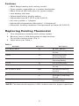
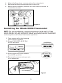
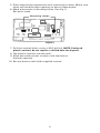
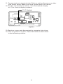
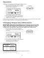
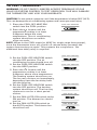
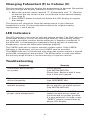
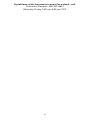
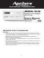
®
ELECTRONIC THERMOSTATS
MODEL 8336
2 Heat / 2 Cool Digital
Heat Pump
User’s Manual
Installation and
Operation
IMPORTANT SAFETY INFORMATION
WARNING:
• Always turn off power at the main power source by unscrewing
fuse or switching circuit breaker to the off position before installing,
removing, cleaning, or servicing thermostat.
• Read all of the information in this manual before installing or
programming this thermostat.
• This is a 24V AC low-voltage thermostat. Do not install on voltages
higher than 30V AC.
• All wiring must conform to local and national building and electrical
codes and ordinances.
• Do not short (jumper) across terminals on the gas valve or at the
system control to test installation. This will damage the thermostat
and void the warranty.
1
Features
• Multi Stage heating and cooling control.
• Zone system compatible as a master thermostat.
• Multi-Colored LED indicators for system status.
• Low battery indicator.
• Fahrenheit/Celsius display option.
• Adjustable from 45°F (4°C) to 90°F (32°C).
• Accuracy within ± 1 degree.
• Adjustable temperature differential: 1-3 degrees F.
• Automatic heating shutdown if temperature exceeds 90°F (32°C).
Replacing Existing Thermostat
1. Turn off power to heating and cooling system.
2. Remove cover of old thermostat to expose wires.
Do not disconnect wires. (Fig. 1)
3. Label wires per Table 1.
Table 1
Old Label
New Label
Description
R, V-VR or VR-R
R
24 VAC, Return
Y, Y1 or M
Y
Stage 1 Cooling/Heating
Circuit
O or R
O
Reversing Valve,
(Cooling Mode)
B
B
Reversing Valve
(Heating Mode)
F or G
G
Fan control relay
Y2
Y2
2nd Stage Cooling
Circuit
W1 or W2 or W-U
W2
2nd Stage Heating
Control
L or X
L
System Monitor LED
E
E
Emergency Heating
Circuit
C, X or B
C
24 VAC, Transformer
Common Side
*NOTE: This thermostat requires a 24V common wire for proper operation.
2
4. After labeling wires, remove wires from terminals.
5. Remove existing thermostat base from wall.
6. Refer to the following section for instructions on how to
install thermostat.
Figure 1
Installing the Model 8336 Thermostat
NOTE: For new installations, mount thermostat on inside wall, 4-5 feet
above the floor. Do not install behind a door, in a corner, near air vents, in
direct sunlight, or near any heat or steam generating fixtures. Installation
at these places will affect thermostat operation.
1. Turn power off to the heating
and cooling systems.
2. Place COOL-OFF-HEAT-EM
In OFF position.
>
>
COOL-OFF-HEAT-EM
COOL-OFF-HEAT-EM
FAN: AUTO - ON
AUX
CHECK EMER
3. Place FAN: AUTO-ON switch
Into AUTO position.
FAN: AUTO - ON
4. Remove the cover using a coin
or screwdriver.
Figure 2
3
5. Place thermostat against the wall at desired location. Make sure
wires will feed through opening on base of thermostat.
6. Mark placement of mounting holes. See Fig. 3.
Set base aside.
Mounting Holes
Batteries NOT Required.
figure 3
7. Drill the marked holes using a 3/16" drill bit. NOTE: Enclosed
plastic anchors do not require a drilled hole for drywall.
8. Tap plastic anchors into the wall.
9. Align base with plastic anchors and feed wires
through opening.
10. Secure base to wall with supplied screws.
4
11. Connect wires to terminal strip. Refer to wiring diagrams on other
side of this sheet. Make sure wire connections are secure.
12. Put the °F/°C switch to either °F for Fahrenheit display
or °C for Celsius display readout.
°F/°C Switch
Batteries NOT Required.
figure 4
13. Replace cover onto thermostat by snapping into place.
14. Turn on power to system. Test thermostat as described
in the following section.
5
Operation
COOL-OFF-HEAT-EM
FAN: AUTO - ON
>
>
>
AUX
C
CHECK EMER
>
>
>
>
>
Setting or Changing the Setpoint Temperature
1. Press either the
or
button.
The display will show the current
temperature setpoint.
2. Press either the
or
button
to adjust the temperature setting
either up or down.
The display will return to the room temperature display five seconds after
the last input and the new setpoint will be saved.
Changing Temperature Differential
COOL-OFF-HEAT-EM
FAN: AUTO - ON
AUX
CHECK EMER
>
>
>
>
2. Press either the
or
button
to adjust the temperature
differential up or down.
The display will show:
Differential
Setting
Degrees
1
1°F/.5°C
2
2°F/1.0°C
3
3°F/1.5°C
The display will return to the room temperature five
seconds after the last input.
6
>
>
>
>
IMPORTANT: The temperature differential is factory set at 1 (1°). This
means that whenever the room temperature changes by one half of a
degree from the temperature setting, the system will turn on. If the
system turns on too often, increase the temperature differential.
1. Press both
and
buttons
at the same time and hold for one
second.
To Test Thermostat
WARNING: DO NOT SHORT (JUMPER) ACROSS TERMINALS OF GAS
VALVE OR SYSTEM CONTROL TO TEST OPERATION. THIS WILL DAMAGE
THE THERMOSTAT AND VOID YOUR WARRANTY.
CAUTION: Do not switch system to cool if the temperature is below 50°F (10°C).
This can damage the air conditioning system and cause personal injury.
1. Place the COOL-OFF-HEAT-EM
switch into the COOL position
COOL-OFF-HEAT-EM
>
2. Press the
button until the
temperature setting is at least
3 degrees below the room
temperature. The air conditioning
system should turn on within
a few seconds.
NOTE: When in the COOL mode (or HEAT for single stage heat pumps),
once the thermostat turns off, a built in 5-minute delay prevents the
system from turning on again. This protects the compressor. No
additional time delay relay is required.
COOL-OFF-HEAT-EM
3. Put the COOL-OFF-HEAT-EM switch
into the OFF position. The air
conditioning system should turn off.
COOL-OFF-HEAT-EM
>
4. Put the COOL-OFF-HEAT-EM switch
into the HEAT position.
5. Press the
button until the
temperature setting is at least
3 degrees above room temperature.
The heating system should turn on.
The fan may not turn on immediately,
depending upon the fan delay built
into the furnace.
6. Put the COOL-OFF-HEAT-EM switch
into the OFF position. The heating
system should turn off. The fan may
continue to run for a short period
of time.
COOL-OFF-HEAT-EM
FAN: AUTO - ON
7. Put the FAN: AUTO-ON switch to the
ON position. The blower fan should
turn on.
8. Put the FAN: AUTO-ON switch to
the AUTO position. The blower fan
should turn off.
7
FAN: AUTO - ON
Changing Fahrenheit (F) to Celsius (C)
The thermostat is preset to display the temperature in degrees Fahrenheit.
You may change the display readout to Celsius if desired.
1. Move the manual switch marked “F” (Fahrenheit) and “C” (Celsius)
located at the top center of the circuit board to the desired setting.
(see page 5)
2. Press RESET button located lust below the LCD display to register
the change.
The display will change to show the temperature in your desired
temperature scale. To return the thermostat to its original setting,
repeat steps 1 and 2 above.
LED Indicators
The LED indicators are used to indicate system activity. The AUX indicator
illuminates during a call for second stage heating. The auxiliary stages
are used to maintain comfort during extremes in weather conditions. If
the AUX LED is illuminated too frequently during periods of moderate
temperature, check the differential settings (page 6).
The CHECK indicator is used to monitor system status. If the CHECK
indicator is illuminated, call your local HVAC service provider.
The EMER indicator is illuminated only when the system switch is moved
to the EM, emergency heat position. The EM position is used only when
the primary stage of heat is not functioning or requires service.
Troubleshooting
Symptom
Remedy
Thermostat does not turn
on system.
Check Wiring
(see INSTALLATION).
Check fuse. Replace with 2 amp
fuse if fuse has opened.
Thermostat turns on and
off too frequently.
Increase Temperature Differential
(see DIFFERENTIAL).
System fan does not
operate properly.
Move fan option switch to either
gas or electric, to match system
(see INSTALLATION).
Thermostat does not display
proper room temperature.
Check “F” Fahrenheit /”C” Celsius
switch located at top center of
circuit board for proper position.
If a new selection is made, press
“RESET” button located directly
below LCD display.
8
If problems with thermostat cannot be solved, call:
Technical Support: 608-257-8801
Monday-Friday 7:45 am-5:00 pm CST
9
Wiring Diagrams
The following is just a sample of the most common types of HVAC
systems. Refer to your systems installation manual for wiring information.
APRILAIRE MODEL 8336 HEAT PUMP THERMOSTAT CONVERSION TO CARRIER
SPLIT SYSTEM CONDENSORS AND HEAT PUMP SYSTEMS
APRILAIRE MODEL 8336 HEAT PUMP THERMOSTAT
CARRIER LOW VOLTAGE TERMINAL BOARD
R
R
Y
O
O
Y1
B
G
E
W2
L
C
Y2
24 VAC, RETURN
COMPRESSOR CONTACTOR
REVERSING VALVE [COOLING MODE]
FAN CONTACTOR CIRCUIT
G
EMERGENCY HEATING CIRCUIT
E
2ND. STAGE HEATING CIRCUIT
W2
SYSTEM MONITOR LED
L
24 VAC, COMMON
C
W3
THE LOW VOLTAGE TERMINAL DESIGNATIONS AND THEIR DESCRIPTION AND/OR
FUNCTION ARE USED ON ALL SPLIT SYSTEM CONDENSORS AND HEAT PUMPS
APRILAIRE MODEL 8336 HEAT PUMP CONVERSION TO COLEMAN HEAT PUMPS
3000 SERIES HEAT PUMP SYSTEMS
APRILAIRE MODEL 8336 HEAT PUMP THERMOSTAT
COLEMAN LOW VOLTAGE TERMINAL BOARD
R
R
Y
B
O
Y1
B
G
E
W2
L
C
Y2
24 VAC, RETURN
COMPRESSOR CONTACTOR
REVERSING VALVE [HEATING MODE]
FAN CONTACTOR CIRCUIT
G
EMERGENCY HEATING CIRCUIT
E
2ND. STAGE HEATING CIRCUIT
W2
SYSTEM MONITOR LED
L
24 VAC, COMMON
X
O
THE LOW VOLTAGE TERMINAL DESIGNATIONS AND THEIR DESCRIPTION AND/OR
FUNCTION ARE USED ON ALL SPLIT SYSTEM CONDENSORS AND HEAT PUMPS
10
APRILAIRE MODEL 8336 HEAT PUMP THERMOSTAT CONVERSION TO COMFORTMAKER
CYC SERIES HEAT PUMP SYSTEMS
COMFORTMAKER LOW VOLTAGE TERMINAL BOARD
NOTE 1: E AND W2 TERMINALS
JUMPERED AT THERMOSTAT
NOTE 2: W2 TERMINAL ON
COMFORTMAKER PCB CAPPED
NOTE 3: X TERMINAL ON
COMFORTMAKER PCB CAPPED
R
Y
O
APRILAIRE MODEL 8336 HEAT PUMP THERMOSTAT
R
Y1
O
B
G
E
W2
L
C
Y2
24 VAC, RETURN
COMPRESSOR CONTACTOR
REVERSING VALVE [COOLING MODE]
FAN CONTACTOR CIRCUIT
G
2ND. STAGE HEATING CIRCUIT
W1
OUTDOOR THERMOSTAT [CAPPED]
W2
DEFROST SENSOR [CAPPED]
X
24 VAC, COMMON
C
THE LOW VOLTAGE TERMINAL DESIGNATIONS AND THEIR DESCRIPTION AND/OR
FUNCTION ARE USED ON ALL SPLIT SYSTEM CONDENSORS AND HEAT PUMPS
APRILAIRE MODEL 8336 HEAT PUMP THERMOSTAT CONVERSION TO HEIL-QUAKER
867.814 SERIES AND PH50 SERIES HEAT PUMP SYSTEMS
HEIL-QUAKER LOW VOLTAGE TERMINAL BOARD
NOTE 1: E AND W2 TERMINALS
JUMPERED AT THERMOSTAT
NOTE 2: W2 TERMINAL ON
HEIL-QUAKER PCB CAPPED
R
Y
O
APRILAIRE MODEL 8336 HEAT PUMP THERMOSTAT
R
Y1
O
B
G
E
W2
L
C
Y2
24 VAC, RETURN
COMPRESSOR CONTACTOR
REVERSING VALVE [COOLING MODE]
FAN CONTACTOR CIRCUIT
G
2ND. STAGE HEATING CIRCUIT [SEQUENCER 1]
W1
3RD. STAGE HEATING CIRCUIT [SEQUENCER 2]
W2
24 VAC, COMMON
C
THE LOW VOLTAGE TERMINAL DESIGNATIONS AND THEIR DESCRIPTION AND/OR
FUNCTION ARE USED ON ALL SPLIT SYSTEM CONDENSORS AND HEAT PUMPS
11
APRILAIRE MODEL 8336 HEAT PUMP THERMOSTAT CONVERSION TO PAYNE
RELIANT AND ENDURA MODEL HEAT PUMP SYSTEMS
NOTE 1: W3 TERMINAL ON
PAYNE PCB CAPPED
APRILAIRE MODEL 8336 HEAT PUMP THERMOSTAT
R
PAYNE LOW VOLTAGE TERMINAL BOARD
R
Y
O
Y1
O
B
G
E
W2
L
C
Y2
24 VAC, RETURN
COMPRESSOR CONTACTOR
REVERSING VALVE [COOLING MODE]
FAN CONTACTOR CIRCUIT
G
E
EMERGENCY HEATING CIRCUIT
2ND. STAGE HEATING CIRCUIT
W2
SYSTEM MONITOR LED
L
24 VAC, COMMON
C
3RD. STAGE HEATING CIRCUIT [CAPPED]
W3
THE LOW VOLTAGE TERMINAL DESIGNATIONS AND THEIR DESCRIPTION AND/OR
FUNCTION ARE USED ON ALL SPLIT SYSTEM CONDENSORS AND HEAT PUMPS
APRILAIRE MODEL 8336 HEAT PUMP THERMOSTAT CONVERSION TO RHEEM/RUUD
HEAT PUMP SYSTEMS
APRILAIRE MODEL 8336 HEAT PUMP THERMOSTAT
RHEEM/RUUDLOW VOLTAGE TERMINAL BOARD
R
R
Y
B
O
Y1
B
G
E
W2
L
C
Y2
24 VAC, RETURN
COMPRESSOR CONTACTOR
REVERSING VALVE [HEATING MODE]
FAN CONTACTOR CIRCUIT
G
EMERGENCY HEATING CIRCUIT
E
2ND. STAGE HEATING CIRCUIT
W2
SYSTEM MONITOR LED
L
24 VAC, COMMON
X
B
THE LOW VOLTAGE TERMINAL DESIGNATIONS AND THEIR DESCRIPTION AND/OR
FUNCTION ARE USED ON ALL SPLIT SYSTEM CONDENSORS AND HEAT PUMPS
12
APRILAIRE MODEL 8336 HEAT PUMP THERMOSTAT CONVERSION
TO WEATHERTRON HEAT PUMPS
WEATHERTRON LOW VOLTAGE TERMINAL BOARD
NOTE 1: E AND W2 TERMINALS
JUMPERED AT THERMOSTAT
NOTE 2: X2 TERMINAL CAPPED AT
WEATHERTRON PCB
NOTE 3: T TERMINAL CAPPED AT
WEATHERTRON PCB
R
Y
O
APRILAIRE MODEL 8336 HEAT PUMP THERMOSTAT
R
Y1
O
B
G
E
W2
L
C
Y2
24 VAC, RETURN
COMPRESSOR CONTACTOR
REVERSING VALVE [COOLING MODE]
FAN CONTACTOR CIRCUIT
G
X2
2ND. STAGE HEATING CIRCUIT
W-U
24 VAC, COMMON
B
T
THE LOW VOLTAGE TERMINAL DESIGNATIONS AND THEIR DESCRIPTION AND/OR
FUNCTION ARE USED ON ALL SPLIT SYSTEM CONDENSORS AND HEAT PUMPS
APRILAIRE MODEL 8336 HEAT PUMP THERMOSTAT CONVERSION TO YORK
-E1CS, -E1FB, -E1FH HEAT PUMP SYSTEMS
NOTE 1: E AND W2 TERMINALS
JUMPERED AT THERMOSTAT
YORK LOW VOLTAGE TERMINAL BOARD
R
Y
O
APRILAIRE MODEL 8336 HEAT PUMP THERMOSTAT
R
Y1
O
B
G
E
W2
L
C
Y2
24 VAC, RETURN
COMPRESSOR CONTACTOR
REVERSING VALVE [COOLING MODE]
FAN CONTACTOR CIRCUIT
G
W
2ND. STAGE HEATING CIRCUIT
SYSTEM MONITOR LED
X
24 VAC, COMMON
B
THE LOW VOLTAGE TERMINAL DESIGNATIONS AND THEIR DESCRIPTION AND/OR
FUNCTION ARE USED ON ALL SPLIT SYSTEM CONDENSORS AND HEAT PUMPS
13
APRILAIRE MODEL 8336 HEAT PUMP THERMOSTAT CONVERSION TO LENNOX
CB19 HEAT PUMP SYSTEMS
APRILAIRE MODEL 8336 HEAT PUMP THERMOSTAT
LENNOX LOW VOLTAGE TERMINAL BOARD
R
R
Y
O
O
Y1
B
G
E
W2
L
C
Y2
24 VAC, RETURN
COMPRESSOR CONTACTOR
REVERSING VALVE [COOLING MODE]
FAN CONTACTOR CIRCUIT
G
EMERGENCY HEATING CIRCUIT
E
2ND. STAGE HEATING CIRCUIT
W1
SYSTEM MONITOR LED
L
24 VAC, COMMON
C
T
THE LOW VOLTAGE TERMINAL DESIGNATIONS AND THEIR DESCRIPTION AND/OR
FUNCTION ARE USED ON ALL SPLIT SYSTEM CONDENSORS AND HEAT PUMPS
APRILAIRE MODEL 8336 HEAT PUMP THERMOSTAT CONVERSION TO LENNOX
HP19 AND HP20 HEAT PUMP SYSTEMS
APRILAIRE MODEL 8336 HEAT PUMP THERMOSTAT
R
LENNOX LOW VOLTAGE TERMINAL BOARD
V-VR
M
R
O
Y1
B
G
E
W2
L
C
Y2
24 VAC, RETURN
COMPRESSOR CONTACTOR
REVERSING VALVE [COOLING MODE]
FAN CONTACTOR CIRCUIT
F
EMERGENCY HEATING CIRCUIT
E
2ND. STAGE HEATING CIRCUIT
Y
24 VAC, COMMON
X
THE LOW VOLTAGE TERMINAL DESIGNATIONS AND THEIR DESCRIPTION AND/OR
FUNCTION ARE USED ON ALL SPLIT SYSTEM CONDENSORS AND HEAT PUMPS
14
APRILAIRE MODEL 8336 HEAT PUMP THERMOSTAT CONVERSION TO LENNOX
HP21 WITH CB21 PCB HEAT PUMP SYSTEMS
APRILAIRE MODEL 8336 HEAT PUMP THERMOSTAT
LENNOX LOW VOLTAGE TERMINAL BOARD
R
R-VR
Y1
O
O
Y1
B
G
E
W2
L
C
Y2
24 VAC, RETURN
COMPRESSOR CONTACTOR
REVERSING VALVE [COOLING MODE]
FAN CONTACTOR CIRCUIT
F
EMERGENCY HEATING CIRCUIT
E
2ND. STAGE HEATING CIRCUIT
W1
L
24 VAC, COMMON
X
Y2
THE LOW VOLTAGE TERMINAL DESIGNATIONS AND THEIR DESCRIPTION AND/OR
FUNCTION ARE USED ON ALL SPLIT SYSTEM CONDENSORS AND HEAT PUMPS
APRILAIRE MODEL 8336 HEAT PUMP THERMOSTAT CONVERSION TO LENNOX
HP22 WITH CB19 PCB HEAT PUMP SYSTEMS
APRILAIRE MODEL 8336 HEAT PUMP THERMOSTAT
LENNOX LOW VOLTAGE TERMINAL BOARD
R
R-VR
M
R
O
Y1
B
G
E
W2
L
C
Y2
24 VAC, RETURN
COMPRESSOR CONTACTOR
REVERSING VALVE [HEATING MODE]
FAN CONTACTOR CIRCUIT
F
EMERGENCY HEATING CIRCUIT
E
2ND. STAGE HEATING CIRCUIT
Y
SYSTEM MONITOR LED
L
24 VAC, COMMON
X
2ND. STAGE COOLING CIRCUIT
Y2
THE LOW VOLTAGE TERMINAL DESIGNATIONS AND THEIR DESCRIPTION AND/OR
FUNCTION ARE USED ON ALL SPLIT SYSTEM CONDENSORS AND HEAT PUMPS
15
Limited Warranty
Your Research Products Corporation Aprilaire® Thermostat unit is expressly
warranted for two (2) years from date of installation to be free from defects in
materials and workmanship.
Research Products Corporation’s exclusive obligation under this warranty shall
be to supply, without charge, a replacement for any thermostat which is found
to be defective within a two (2) year period and which is returned, together with
the date of installation, no later than thirty (30) days after said two (2) year
period by you to either your original supplier or to Research Products
Corporation, Madison, Wisconsin 53701.
THIS WARRANTY SHALL NOT OBLIGATE RESEARCH PRODUCTS CORPORATION FOR ANY LABOR COSTS AND SHALL NOT APPLY TO DEFECTS IN
WORKMANSHIP OR MATERIALS FURNISHED BY YOUR INSTALLER AS
CONTRASTED TO DEFECTS IN THE THERMOSTAT ITSELF.
IMPLIED WARRANTIES OF MERCHANTABILITY OR FITNESS FOR A PARTICULAR PURPOSE SHALL BE LIMITED IN DURATION TO THE AFORESAID
TWO YEAR PERIOD. RESEARCH PRODUCTS CORPORATION’S LIABILITY
FOR INCIDENTAL OR CONSEQUENTIAL DAMAGES, OTHER THAN DAMAGES
FOR PERSONAL INJURIES, RESULTING FROM ANY BREACH OF THE AFORESAID IMPLIED WARRANTIES OR THE ABOVE LIMITED WARRANTY IS
EXPRESSLY EXCLUDED. THIS LIMITED WARRANTY IS VOID IF DEFECT(S)
RESULT FROM FAILURE TO HAVE THIS THERMOSTAT INSTALLED BY A
QUALIFIED HEATING AND AIR CONDITIONING CONTRACTOR. IF THE
LIMITED WARRANTY IS VOID DUE TO FAILURE TO USE A QUALIFIED
CONTRACTOR, ALL DISCLAIMERS OF IMPLIED WARRANTIES SHALL BE
EFFECTIVE UPON INSTALLATION.
Some states do not allow limitations on how long an implied warranty lasts or
the exclusion or limitation of incidental or consequential damages, so the
above exclusion or limitations may not apply to you.
This warranty gives you specific legal rights and you may also have other rights
which vary from state to state.
P.O. BOX 1467 • MADISON, WI 53701-1467
Products For Better Indoor Air Quality ™
B2202516 REV. 12/00
16