1
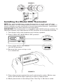
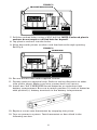
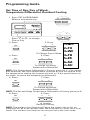
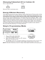
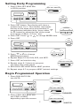
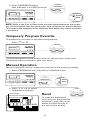
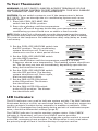
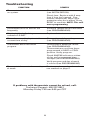
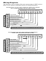
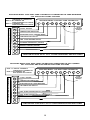
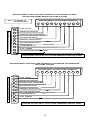
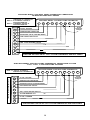
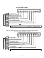
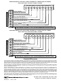
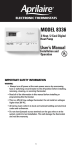
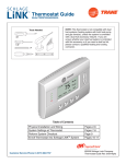
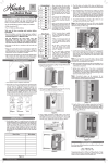
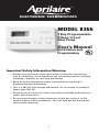
®
ELECTRONIC THERMOSTATS
MODEL 8355
7 Day Programmable
2 Heat / 2 Cool
Heat Pump
User’s Manual
Installation and
Programming
Important Safety Information Warning:
• Always turn off power at the main power source by unscrewing
fuse or switching circuit breaker to the off position before installing,
removing, cleaning, or servicing thermostat.
•
Read all of the information in this manual before installing or
programming this thermostat.
•
This is a 24V AC low-voltage thermostat. Do not install on voltages
higher than 30V AC.
•
All wiring must conform to local and national building and electrical
codes and ordinances.
•
Do not short (jumper) across terminals on the gas valve or at the
system control to test installation. This will damage the thermostat
and void the warranty.
1
Features
• Four pre-programmed setpoints for each day of the week.
• Fast and easy programming for setting all days of the week
simultaneously.
• Energy efficient recovery.
• Residual cooling for added air-conditioning efficiency.
• Two “AA” ENERGIZER brand batteries retain program memory,
even during power outages.
• Low battery indicator.
• Multi-colored LED indicators for system status.
• Zone compatible as master thermostat.
• Fahrenheit/Celsius display option.
• Programmable from 45°F (7°C) to 90°F (32°C).
• Accuracy within ±1 degree.
• Adjustable temperature differential: 1-3 degrees.
• Maintains summer and winter programming.
Replacing Existing Thermostat
1. Turn off power to heating and cooling system.
2. Remove cover of old thermostat to expose wires. Do not
disconnect wires. (Fig. 1)
3. Label wires per Table 1.
TABLE 1
Old Label
New Label
Description
R, V-VR or VR-R
R
24 VAC
Y, Y1 or M
Y1
Stage 1 Cooling/Heating Circuit
O or R
O
Reversing Valve (Cooling Mode)
B
B
Reversing Valve (Heating Mode)
G or F
G
Fan Contactor Circuit
Y2
Y2
2nd Stage Cooling Circuit
W1 or W2 or W-U
W2
L or X
2nd Stage Heating Circuit
L
System Monitor LED
E
E
Emergency Heating Circuit
C, X or B
C
24 VAC, Transformer Common Side
NOTE: This thermostat requires a 24V AC common wire for proper operation.
4. After labeling wires, remove wires from terminals.
5. Remove existing thermostat base from wall.
6. Refer to the following section for instructions on how to
install thermostat.
2
FIGURE 1
Installing the Model 8355 Thermostat
NOTE: For new installations, mount thermostat on inside wall, 4-5 feet
above the floor. Do not install behind a door, in a corner, near air vents, in
direct sunlight, or near any heat or steam generating fixtures. Installation
at these places will affect thermostat operation.
IMPORTANT: This thermostat is compatible with 100% lockout systems. To
reset the system, turn thermostat to OFF position for at least 60 seconds.
1. Turn power off to the heating and cooling systems.
2. Place COOL-OFF-HEAT-EM in OFF position.
COOL-OFF-HEAT-EM
PROG
MAN
>
>
AUX CHECK EMER
SET PROG/MAN
COOL-OFF-HEAT-EM
FAN: AUTO - ON
FAN: AUTO-ON
3. Place FAN: AUTO-ON switch
into AUTO position.
4. Remove the cover using a coin
or screwdriver.
EM
FIGURE 2
5. Place thermostat against the wall at desired location. Make sure
wires will feed through opening on base of thermostat.
6. Mark placement of mounting holes. See Fig. 3. Set base aside.
3
FIGURE 3
MOUNTING HOLES
C L R
Y2 Y1
AM
PM
PROG
MAN
E
G
MORN DAY EVE NITE EER
SET
PROG/MAN
W2
CHANGE
O
B
COOL OFF HEAT EM
FAN AUTO ON
7. Drill the marked holes using a 3/16" drill bit. NOTE: Enclosed plastic
anchors do not require a drilled hole for drywall.
8. Tap plastic anchors into the holes.
9. Align base with plastic anchors and feed wires through opening.
See Fig 4.
FIGURE 4
OPENING
C L R
Y2 Y1
AM
PM
PROG
MAN
E
G
MORN DAY EVE NITE EER
SET
PROG/MAN
W2
CHANGE
O
B
COOL OFF HEAT EM
FAN AUTO ON
10. Secure base to wall with supplied screws.
11. Connect wires to terminal strip. Refer to wiring diagrams on other
side of this sheet. Make sure wire connections are secure.
12. Install two "AA" ENERGIZER brand batteries or equivalent into
battery compartment. Be sure to match positive (+) ends of batteries
with positive (+) battery terminals in the battery compartment.
13. Replace cover onto thermostat by snapping into place.
14. Turn on power to system. Test thermostat as described in the
following section.
4
Programming Guide
Set Time of Day, Day of Week,
Temperature Differential, Residual Cooling
1. Press SET & PROG/MAN.
Release simultaneously.
SET PROG/MAN
PROG
MAN
FAN: AUTO - ON
>
to change
3. Press
>
2. Press
>
>
Press
or
Time of Day.
SET P
To Change Day of Week
5. Press
>
SET P
>
4. Press
>
COOL-OFF-HEAT-EM
>
>
>
AUX CHECK EMER
SET PROG/MAN
To change 1st Stage
Temperature Differential
1=MO
2=TU
3=WE
4=TH
5=FR
6=SA
7=SU
NOTE: The Temperature Differential is Factory preset at 1°. This means
that whenever the room temperature changes by one full degree from
the temperature setting, the system will turn on. If the system turns on
too often, increase the temperature differential.
>
SET P
7. Press
>
6. Press
>
SET P
>
To change 2nd Stage
Temperature Differential
NOTE: The Second Stage Temperature Differential is Factory preset at 2°.
8. Press
9. Press
To change
Residual Cooling
NOTE: The residual cool feature will keep the system fan on for an
additional 30, 60 or 90 seconds after the compressor cycles off in cool
mode. The residual cool feature can only be set in the cool mode.
5
Changing Fahrenheit (F) to Celsius (C)
Press
>
Press and Hold SET
SET P
Release both simultaneously.
Energy Efficient Recovery
The energy efficient recovery feature looks ahead up to 2 hours prior to the
end of the setback (or set-up) period to begin monitoring performance and
calculating when to turn on your system. It also determines whether the auxiliary heat or cool stages should be activated prior to setpoint time to meet
your chosen setpoint temperature. The thermostat will indicate “EER” in the
display when this program feature is active. The energy efficient recovery
feature will lockout the auxiliary stages until 20 minutes prior to upcoming
setpoint time to utilize the most energy efficient first stage. The auxiliary
stages of heating and cooling will be available during this lock-out period
to maintain the setpoint temperature should the system not be able to
keep up with the heating or cooling demand.
Simple Programming Mode
COOL-OFF-HEAT-EM
PROG
MAN
SET PROG/MAN
COOL-OFF-HEAT-EM
FAN: AUTO - ON
>
>
>
AUX CHECK EMER
SET P
>
1. Place COOL-OFF-HEAT-EM
in COOL or HEAT position.
2. Press & Hold SET. Press the
Release simultaneously.
button.
3. The MORN indicator should be blinking. Program the Time-of-Day and
the temperature as outlined in the Setting Daily Program section.
NOTE: Use this function to set all 7 days of the week with the same program.
6
Setting Daily Programming
1. Place COOL-OFF-HEAT-EM
in COOL position.
COOL-OFF-HEAT-EM
PROG
MAN
COOL-OFF-HEAT-EM
FAN: AUTO - ON
SET PR
>
3. Press SET. Press
>
>
>
>
2. Press SET button. The display will show a
number from 1 to 7. This number represents
the day of the week to be programmed. If
programming individual days, press either
or
button to adjust the day of the week
to program (1=Mon., 2=Tues., etc.).
>
>
>
AUX CHECK EMER
SET PROG/MAN
or
to change MORN time.
4. Press SET.
SET PR
PROG
MAN
FAN: AUTO - ON
>
COOL-OFF-HEAT-EM
>
>
>
>
>
AUX CHECK EMER
SET PROG/MAN
5. Press
or
to change
MORN temperature.
6. Repeat Steps 2-5 for DAY, EVE, and NITE.
7. Press SET to finish this day.
COOL-OFF-HEAT-EM
8. Repeat steps 2–7 above to program
any other day of the week.
9. Shift COOL-OFF-HEAT-EM to HEAT position.
10. Repeat steps 2-7 to program HEAT (winter) settings.
Begin Programmed Operation
1. Place FAN: AUTO-ON
into AUTO.
FAN: AUTO-ON
PROG
MAN
>
>
AUX CHECK EMER
SET PROG/MAN
COOL-OFF-HEAT-EM
COOL-OFF-HEAT-EM
FAN: AUTO - ON
SUMMER
2. Place COOL-OFF-HEAT-EM
into COOL or HEAT,
depending upon the season.
COOL-OFF-HEAT-EM
7
WINTER
3. Press PROG/MAN button
until indicator is in PROG position.
ET PROG/MAN
C
PROG
MAN
AUX CHECK EMER
>
>
PROG
SET PROG/MAN
COOL-OFF-HEAT-EM
FAN: AUTO - ON
MAN
NOTE: While in the Cool or Heat mode, once the thermostat turns the system
off, a built-in delay keeps the compressor from turning on for about 5 minutes.
This protects the compressor. No additional time delay relay (delay on break)
is necessary.
Temporary Program Override
>
PROG
>
or
>
Press
>
To temporarily increase or decrease temperature
MAN
>
>
AUX CHECK EMER
SET PROG/MAN
COOL-OFF-HEAT-EM
FAN: AUTO - ON
The thermostat will automatically return to the program at the next
scheduled setting change or after four hours.
Manual Operation
Manual operation allows continuous override of the program settings.
1. Press PROG/MAN until indicator is in MAN position.
PROG
MAN
AUX CHECK EMER
>
>
T PROG/MAN
SET PROG/MAN
COOL-OFF-HEAT-EM
PROG
FAN: AUTO - ON
MAN
C L R
PROG
MAN
MORN DAY EVE NITE EER
SET
PROG/MAN
E
G
W2
CHANGE
Y2 Y1
AM
PM
>
>
Reset
RESET BUTTON
O
B
COOL OFF HEAT EM
FAN AUTO ON
To reset the thermostat
to factory pre-programmed
conditions, press the reset
button located directly to
the right of the display.
8
>
>
2. Press or
to adjust
temperature settings.
To Test Thermostat
WARNING: DO NOT SHORT (JUMPER) ACROSS TERMINALS OF GAS
VALVE OR SYSTEM CONTROL TO TEST OPERATION. THIS WILL DAMAGE
THE THERMOSTAT AND VOID YOUR WARRANTY.
CAUTION: Do not switch system to cool if the temperature is below
50°F (10°C). This can damage the air conditioning system and cause
personal injury.
COOL-OFF-HEAT-EM
1. Place the COOL-OFF-HEAT-EM
switch into the COOL position
>
2. Press the button until the temperature
setting is at least 3 degrees below the room temperature. The air
conditioning system should turn on within a few seconds.
NOTE: While in the Cool or Heat mode once the thermostat turns the system
off, a built-in delay keeps the compressor from turning on for about 5 minutes.
This protects the compressor. No additional time delay relay (delay on break)
is necessary.
3. Put the COOL-OFF-HEAT-EM switch into
the OFF position. The air conditioning
system should turn off. The fan may
continue to run for a short period of time.
COOL-OFF-HEAT-EM
COOL-OFF-HEAT-EM
>
4. Put the COOL-OFF-HEAT-EM switch
into the HEAT position.
5. Press the button until the temperature setting is at least
3 degrees above room temperature. The heating system should turn
on. The fan may not turn on immediately, depending upon the fan
delay built into the furnace.
6. Put the COOL-OFF-HEAT-EM switch
into the OFF position. The heating
system should turn off. Once again,
the fan may have a delay.
COOL-OFF-HEAT-EM
FAN: AUTO - ON
7. Put the FAN: AUTO-ON switch
to the ON position. The blower
fan should turn on.
8. Put the FAN: AUTO-ON switch
to the AUTO position. The blower
fan should turn off.
FAN: AUTO-ON
LED Indicators
The LED indicators are used to indicate system activity. The AUX indicator
illuminates during a call for second stage heating. The auxiliary stages are
used to maintain comfort during extremes in weather conditions. If the
AUX LED is illuminated too frequently during periods of moderate temperature, check the differential settings (page 5).
The CHECK indicator is used to monitor system status. If the CHECK
indicator is illuminated, call your local HVAC service provider.
The EMER indicator is illuminated only when the system switch is moved
to the EM, emergency heat position. The EM position is only used when
the primary stage of heat is not functioning or requires service.
9
Troubleshooting
SYMPTOM
REMEDY
Thermostat does not turn
on system.
Check Wiring
(see INSTALLATION).
Check fuse. Replace with 3 amp
fuse if fuse has opened. Five
minute compressor short cycle
protection may be in effect. Press
RESET to override. NOTE: This will
erase programming.
Thermostat turns on and off too
frequently.
Increase Temperature Differential
(see PROGRAMMING).
Display is blank, flashing or
constant "LO BAT."
Replace batteries.
Time shown on display is not the
current time of day.
Change time of day setting
(see PROGRAMMING).
Thermostat does not follow
program.
Thermostat in MANUAL mode
(see PROGRAMMING).
Thermostat may not have been
programmed in HEAT or COOL
position. Verify program.
Check AM/PM indicators at time
of day and programmed time
changes (see PROGRAMMING).
Verify program and day of week
is correct (see PROGRAMMING).
Thermostat does not advance day
of week.
To view or change day of week
use method on page 5.
If problems with thermostats cannot be solved, call:
Technical Support: 608-257-8801
Monday-Friday 7:45 am-5:00 pm CST
10
Wiring Diagrams
The following is just a sample of the most common types of HVAC systems.
Refer to your system’s installation manual for wiring information.
APRILAIRE MODEL 8355 HEAT PUMP THERMOSTAT CONVERSION TO CARRIER
SPLIT SYSTEM CONDENSORS AND HEAT PUMP SYSTEMS
APRILAIRE MODEL 8355 HEAT PUMP THERMOSTAT
CARRIER LOW VOLTAGE TERMINAL BOARD
R
R
Y
O
O
Y1
B
G
E
W2
L
C
Y2
24 VAC, RETURN
COMPRESSOR CONTACTOR
REVERSING VALVE [COOLING MODE]
FAN CONTACTOR CIRCUIT
G
EMERGENCY HEATING CIRCUIT
E
2ND. STAGE HEATING CIRCUIT
W2
SYSTEM MONITOR LED
L
24 VAC, COMMON
C
W3
THE LOW VOLTAGE TERMINAL DESIGNATIONS AND THEIR DESCRIPTION AND/OR
FUNCTION ARE USED ON ALL SPLIT SYSTEM CONDENSORS AND HEAT PUMPS
APRILAIRE MODEL 8355 HEAT PUMP THERMOSTAT CONVERSION TO
ROBERT SHAW 3000 SERIES HEAT PUMP SYSTEMS
APRILAIRE MODEL 8355 HEAT PUMP THERMOSTAT
COLEMAN LOW VOLTAGE TERMINAL BOARD
R
R
Y
B
O
Y1
B
G
E
W2
L
C
Y2
24 VAC, RETURN
COMPRESSOR CONTACTOR
REVERSING VALVE [HEATING MODE]
FAN CONTACTOR CIRCUIT
G
EMERGENCY HEATING CIRCUIT
E
2ND. STAGE HEATING CIRCUIT
W2
SYSTEM MONITOR LED
L
24 VAC, COMMON
X
O
THE LOW VOLTAGE TERMINAL DESIGNATIONS AND THEIR DESCRIPTION AND/OR
FUNCTION ARE USED ON ALL SPLIT SYSTEM CONDENSORS AND HEAT PUMPS
11
APRILAIRE MODEL 8355 HEAT PUMP THERMOSTAT CONVERSION TO COMFORTMAKER
CYC SERIES HEAT PUMP SYSTEMS
COMFORTMAKER LOW VOLTAGE TERMINAL BOARD
NOTE 1: E AND W2 TERMINALS
JUMPERED AT THERMOSTAT
NOTE 2: W2 TERMINAL ON
COMFORTMAKER PCB CAPPED
NOTE 3: X TERMINAL ON
COMFORTMAKER PCB CAPPED
R
Y
O
APRILAIRE MODEL 8355 HEAT PUMP THERMOSTAT
R
Y1
O
B
G
E
W2
L
C
Y2
Field
Installed
Jumper
24 VAC, RETURN
COMPRESSOR CONTACTOR
REVERSING VALVE [COOLING MODE]
FAN CONTACTOR CIRCUIT
G
2ND. STAGE HEATING CIRCUIT
W1
OUTDOOR THERMOSTAT [CAPPED]
W2
DEFROST SENSOR [CAPPED]
X
24 VAC, COMMON
C
THE LOW VOLTAGE TERMINAL DESIGNATIONS AND THEIR DESCRIPTION AND/OR
FUNCTION ARE USED ON ALL SPLIT SYSTEM CONDENSORS AND HEAT PUMPS
APRILAIRE MODEL 8355 HEAT PUMP THERMOSTAT CONVERSION TO HEIL-QUAKER
867.814 SERIES AND PH50 SERIES HEAT PUMP SYSTEMS
HEIL-QUAKER LOW VOLTAGE TERMINAL BOARD
NOTE 1: E AND W2 TERMINALS
JUMPERED AT THERMOSTAT
NOTE 2: W2 TERMINAL ON
HEIL-QUAKER PCB CAPPED
R
Y
O
APRILAIRE MODEL 8355 HEAT PUMP THERMOSTAT
R
O
Y1
B
G
E
W2
L
C
Y2
Field
Installed
Jumper
24 VAC, RETURN
COMPRESSOR CONTACTOR
REVERSING VALVE [COOLING MODE]
FAN CONTACTOR CIRCUIT
G
2ND. STAGE HEATING CIRCUIT [SEQUENCER 1]
W1
3RD. STAGE HEATING CIRCUIT [SEQUENCER 2]
W2
24 VAC, COMMON
C
THE LOW VOLTAGE TERMINAL DESIGNATIONS AND THEIR DESCRIPTION AND/OR
FUNCTION ARE USED ON ALL SPLIT SYSTEM CONDENSORS AND HEAT PUMPS
12
APRILAIRE MODEL 8355 HEAT PUMP THERMOSTAT CONVERSION TO PAYNE
RELIANT AND ENDURA MODEL HEAT PUMP SYSTEMS
NOTE 1: W3 TERMINAL ON
PAYNE PCB CAPPED
APRILAIRE MODEL 8355 HEAT PUMP THERMOSTAT
R
PAYNE LOW VOLTAGE TERMINAL BOARD
R
Y
O
O
Y1
B
G
E
W2
L
C
Y2
24 VAC, RETURN
COMPRESSOR CONTACTOR
REVERSING VALVE [COOLING MODE]
FAN CONTACTOR CIRCUIT
G
E
EMERGENCY HEATING CIRCUIT
2ND. STAGE HEATING CIRCUIT
W2
SYSTEM MONITOR LED
L
24 VAC, COMMON
C
3RD. STAGE HEATING CIRCUIT [CAPPED]
W3
THE LOW VOLTAGE TERMINAL DESIGNATIONS AND THEIR DESCRIPTION AND/OR
FUNCTION ARE USED ON ALL SPLIT SYSTEM CONDENSORS AND HEAT PUMPS
APRILAIRE MODEL 8355 HEAT PUMP THERMOSTAT CONVERSION TO RHEEM/RUUD
HEAT PUMP SYSTEMS
APRILAIRE MODEL 8355 HEAT PUMP THERMOSTAT
RHEEM/RUUDLOW VOLTAGE TERMINAL BOARD
R
R
Y
B
O
Y1
B
G
E
W2
L
C
Y2
24 VAC, RETURN
COMPRESSOR CONTACTOR
REVERSING VALVE [HEATING MODE]
FAN CONTACTOR CIRCUIT
G
EMERGENCY HEATING CIRCUIT
E
2ND. STAGE HEATING CIRCUIT
W2
SYSTEM MONITOR LED
L
24 VAC, COMMON
X
B
THE LOW VOLTAGE TERMINAL DESIGNATIONS AND THEIR DESCRIPTION AND/OR
FUNCTION ARE USED ON ALL SPLIT SYSTEM CONDENSORS AND HEAT PUMPS
13
APRILAIRE MODEL 8355 HEAT PUMP THERMOSTAT CONVERSION
TO WEATHERTRON HEAT PUMPS
WEATHERTRON LOW VOLTAGE TERMINAL BOARD
NOTE 1: E AND W2 TERMINALS
JUMPERED AT THERMOSTAT
NOTE 2: X2 TERMINAL CAPPED AT
WEATHERTRON PCB
NOTE 3: T TERMINAL CAPPED AT
WEATHERTRON PCB
R
Y
O
APRILAIRE MODEL 8355 HEAT PUMP THERMOSTAT
R
Y1
O
B
G
E
W2
L
Y2
C
Field
Installed
Jumper
24 VAC, RETURN
COMPRESSOR CONTACTOR
REVERSING VALVE [COOLING MODE]
FAN CONTACTOR CIRCUIT
G
X2
2ND. STAGE HEATING CIRCUIT
W-U
24 VAC, COMMON
B
T
THE LOW VOLTAGE TERMINAL DESIGNATIONS AND THEIR DESCRIPTION AND/OR
FUNCTION ARE USED ON ALL SPLIT SYSTEM CONDENSORS AND HEAT PUMPS
APRILAIRE MODEL 8355 HEAT PUMP THERMOSTAT CONVERSION TO YORK
-E1CS, -E1FB, -E1FH HEAT PUMP SYSTEMS
NOTE 1: E AND W2 TERMINALS
JUMPERED AT THERMOSTAT
YORK LOW VOLTAGE TERMINAL BOARD
R
Y
O
APRILAIRE MODEL 8355 HEAT PUMP THERMOSTAT
R
O
Y1
B
G
E
W2
L
C
Y2
Field
Installed
Jumper
24 VAC, RETURN
COMPRESSOR CONTACTOR
REVERSING VALVE [COOLING MODE]
FAN CONTACTOR CIRCUIT
G
W
2ND. STAGE HEATING CIRCUIT
SYSTEM MONITOR LED
X
24 VAC, COMMON
B
THE LOW VOLTAGE TERMINAL DESIGNATIONS AND THEIR DESCRIPTION AND/OR
FUNCTION ARE USED ON ALL SPLIT SYSTEM CONDENSORS AND HEAT PUMPS
14
APRILAIRE MODEL 8355 HEAT PUMP THERMOSTAT CONVERSION TO LENNOX
CB19 HEAT PUMP SYSTEMS
APRILAIRE MODEL 8355 HEAT PUMP THERMOSTAT
LENNOX LOW VOLTAGE TERMINAL BOARD
R
R
Y
O
O
Y1
B
G
E
W2
L
C
Y2
24 VAC, RETURN
COMPRESSOR CONTACTOR
REVERSING VALVE [COOLING MODE]
FAN CONTACTOR CIRCUIT
G
EMERGENCY HEATING CIRCUIT
E
2ND. STAGE HEATING CIRCUIT
W1
SYSTEM MONITOR LED
L
24 VAC, COMMON
C
T
THE LOW VOLTAGE TERMINAL DESIGNATIONS AND THEIR DESCRIPTION AND/OR
FUNCTION ARE USED ON ALL SPLIT SYSTEM CONDENSORS AND HEAT PUMPS
APRILAIRE MODEL 8355 HEAT PUMP THERMOSTAT CONVERSION TO LENNOX
HP19 AND HP20 HEAT PUMP SYSTEMS
APRILAIRE MODEL 8355 HEAT PUMP THERMOSTAT
R
LENNOX LOW VOLTAGE TERMINAL BOARD
V-VR
M
R
O
Y1
B
G
E
W2
L
C
Y2
24 VAC, RETURN
COMPRESSOR CONTACTOR
REVERSING VALVE [COOLING MODE]
FAN CONTACTOR CIRCUIT
F
EMERGENCY HEATING CIRCUIT
E
2ND. STAGE HEATING CIRCUIT
Y
24 VAC, COMMON
X
THE LOW VOLTAGE TERMINAL DESIGNATIONS AND THEIR DESCRIPTION AND/OR
FUNCTION ARE USED ON ALL SPLIT SYSTEM CONDENSORS AND HEAT PUMPS
15
APRILAIRE MODEL 8355 HEAT PUMP THERMOSTAT CONVERSION TO LENNOX
HP21 WITH CB21 PCB HEAT PUMP SYSTEMS
APRILAIRE MODEL 8355 HEAT PUMP THERMOSTAT
LENNOX LOW VOLTAGE TERMINAL BOARD
R
R-VR
Y1
O
Y1
O
B
G
E
W2
L
C
Y2
24 VAC, RETURN
COMPRESSOR CONTACTOR
REVERSING VALVE [COOLING MODE]
FAN CONTACTOR CIRCUIT
F
EMERGENCY HEATING CIRCUIT
E
2ND. STAGE HEATING CIRCUIT
W1
L
24 VAC, COMMON
X
Y2
THE LOW VOLTAGE TERMINAL DESIGNATIONS AND THEIR DESCRIPTION AND/OR
FUNCTION ARE USED ON ALL SPLIT SYSTEM CONDENSORS AND HEAT PUMPS
APRILAIRE MODEL 8355 HEAT PUMP THERMOSTAT CONVERSION TO LENNOX
HP22 WITH CB19 PCB HEAT PUMP SYSTEMS
APRILAIRE MODEL 8355 HEAT PUMP THERMOSTAT
LENNOX LOW VOLTAGE TERMINAL BOARD
R
R-VR
M
R
Y1
O
B
G
E
W2
L
C
Y2
24 VAC, RETURN
COMPRESSOR CONTACTOR
REVERSING VALVE [HEATING MODE]
FAN CONTACTOR CIRCUIT
F
EMERGENCY HEATING CIRCUIT
E
2ND. STAGE HEATING CIRCUIT
Y
SYSTEM MONITOR LED
L
24 VAC, COMMON
X
2ND. STAGE COOLING CIRCUIT
Y2
THE LOW VOLTAGE TERMINAL DESIGNATIONS AND THEIR DESCRIPTION AND/OR
FUNCTION ARE USED ON ALL SPLIT SYSTEM CONDENSORS AND HEAT PUMPS
Limited Warranty
Your Research Products Corporation Aprilaire® Thermostat unit is expressly warranted for two (2) years from date of installation to be free from defects in materials and workmanship. Research Products Corporation’s exclusive obligation under this warranty shall be to supply, without charge, a replacement for any thermostat which is found to be defective within a two (2) year
period and which is returned, together with the date of installation, no later than thirty (30) days after said two (2) year period
by you to either your original supplier or to Research Products Corporation, Madison, Wisconsin 53701.
THIS WARRANTY SHALL NOT OBLIGATE RESEARCH PRODUCTS CORPORATION FOR ANY LABOR COSTS AND SHALL NOT
APPLY TO DEFECTS IN WORKMANSHIP OR MATERIALS FURNISHED BY YOUR INSTALLER AS CONTRASTED TO DEFECTS
IN THE THERMOSTAT ITSELF.
IMPLIED WARRANTIES OF MERCHANTABILITY OR FITNESS FOR A PARTICULAR PURPOSE SHALL BE LIMITED IN DURATION TO THE AFORESAID TWO YEAR PERIOD. RESEARCH PRODUCTS CORPORATION’S LIABILITY FOR INCIDENTAL OR
CONSEQUENTIAL DAMAGES, OTHER THAN DAMAGES FOR PERSONAL INJURIES, RESULTING FROM ANY BREACH OF THE
AFORESAID IMPLIED WARRANTIES OR THE ABOVE LIMITED WARRANTY IS EXPRESSLY EXCLUDED. THIS LIMITED WARRANTY IS VOID IF DEFECT(S) RESULT FROM FAILURE TO HAVE THIS THERMOSTAT INSTALLED BY A QUALIFIED HEATING
AND AIR CONDITIONING CONTRACTOR. IF THE LIMITED WARRANTY IS VOID DUE TO FAILURE TO USE A QUALIFIED CONTRACTOR, ALL DISCLAIMERS OF IMPLIED WARRANTIES SHALL BE EFFECTIVE UPON INSTALLATION.
Some states do not allow limitations on how long an implied warranty lasts or the exclusion or limitation of incidental or consequential damages, so the above exclusion or limitations may not apply to you. This warranty gives you specific legal rights
and you may also have other rights which vary from state to state.
P.O. BOX 1467 • MADISON, WI 53701-1467
Products For Better Indoor Air Quality ™
B2202518
REV. 12/00