1
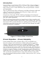
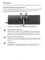
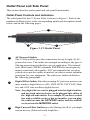
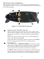
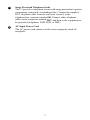
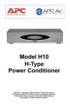
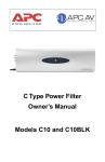
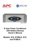
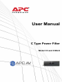
User Manual
C Type Power Filter
Model C3 and C3BLK
Entire contents copyright © 2010 American Power Conversion
Corporation. All rights reserved. Reproduction in whole or in
part without permission is prohibited. APC, the APC logo, and
TRADE MARK NAMES are trademarks of American Power
Conversion Corporation. All other trademarks, product names,
and corporate names are the property of their respective owners
and are used for informational purposes only.
Table of Contents
Safety Information
i
Protect Your Investment
iii
Class B Labeling and Instruction Manual Requirements vi
Introduction
Proven Expertise…Proven Reliability
Safety Precautions
Package Contents
Unit Power Capacity
1
1
2
2
2
Features
Surge Protection
Isolated Noise Filter Banks (INFB)
Full Outlet Coverage
3
3
3
3
Top Panel
Top Panel Controls and Indicators
4
4
Outlet Panel and Side Panel
Outlet Panel Controls and Indicators
Side Panel Controls and Indicators
5
5
6
Installation
Make Connections
Apply Power
FCC Compliance Information
8
8
8
8
Technical Specifications
9
Troubleshooting
10
APC Technical Support
11
v
vi
Protect Your Investment
Congratulations and thank you for selecting and investing in APC's Model C5
Power Filter. At APC, we know you have made an intelligent choice sure to
reward you for many years. To ensure you receive all the benefits and protection that accompany your purchase, please take a few minutes to fill out and
mail the enclosed Warranty Registration Card, or complete the online form at:
www.apc.com.
Note: Under California law, failure to register your purchase may not exclude
you from provisions of the Warranty and Equipment Protection Policy.
The benefits of warranty registration are outlined below.
Registration
Verification
Confirmation
By registering your
purchase now, it
guarantees you will
receive all the information
and special offers you
qualify for as the owner of
this product.
By registering your
purchase now, it confirms
your right to maximum
protection under the
terms and conditions of
the Warranty, and
Equipment Protection
Policy.
By registering your
purchase now, you have a
way to confirm yourself
as the owner of the
product in the event of
fire, theft or loss.
Safety Symbols
This “bolt of lightning”
indicates uninsulated material
within your unit that may
cause an electrical shock. For
the safety of everyone in your
home, please do not remove
the product cover.
!
This “exclamation point” calls
attention to features for which
you should read about in this
Manual to prevent operating
and maintenance problems.
Warnings, Cautions and Notes
Warnings
Warnings provide
information about a
procedure that, if not
performed exactly as
stated, may result in
injury or death.
Cautions
Cautions provide
information about a
procedure that, if
not performed
exactly as stated,
may result in
equipment damage.
iii
Notes
Notes provide
information that is
essential to
highlight.
Class B Labeling and
Instruction Manual Requirements
Devices subject to Certification must be labeled with an FCC Identifier.
Devices subject to Verification or Certification must be labeled with the
following compliance statement:
This device complies with Part 15 of the FCC Rules. Operation is
subject to the following two conditions: (1) this device may not
cause harmful interference, and (2) this device must accept any
interference received, including interference that may cause
undesired operation.
In addition, for a Class B digital device or peripheral, the instructions
furnished the user shall include the following or similar statement, placed in a
prominent location in the text of the manual:
Warning: Changes or modifications to this unit not expressly
approved by the party responsible for compliance could void the
user’s authority to operate the equipment.
NOTE: This equipment has been tested and found to comply with
the limits for a Class B digital device, pursuant to Part 15 of the CC
Rules. These limits are designed to provide reasonable protection
against harmful interference in a residential installation. This
equipment generates, uses, and can radiated radio frequency
energy and, if not installed and used in accordance with the
instructions, may cause harmful interference to radio
communications. However, there is no guarantee that interference
will not occur in a particular installation. If this equipment does
cause harmful interference to radio or television reception, which
can be determined by turning the equipment off and on, the user
is encouraged to try to correct the interference by one or more of
the following measures:
Reorient or relocate the receiving antenna.
–
–
–
Increase the separation between the equipment and receiver.
Connect the equipment into an outlet on a circuit different
from that to which the receiver is connected.
Consult the dealer or an experienced audio TV technician for
help.
If shielded cables or other specialized accessories are necessary for the unit
to achieve compliance, a statement similar to the following should be added:
Shielded cables must be used with this unit to ensure compliance
with the Class B FCC limits.
iv
Introduction
Congratulations on purchasing APC’s C3 Power Filter, shown in Figure 1.
The power filter comes in two models. The C3 is silver and the C3BLK is
black. However, the C3 and C3BLK have the same performance, features
and functionality.
The C3/C3BLK Power Filter will protect your high performance audio and
video (AV) system from damage caused by power surges, spikes and
lightning. Protection is guaranteed.
Isolated noise filter bank (INFB) technology eliminates electromagnetic
interference and radio frequency interference (EMI/RFI) as sources of audio
and video signal degradation.
Data line surge protection jacks stop surges from traveling over phone and
ethernet lines. Digital Satellite System (DSS), cable modem (CM), and cable
television (CATV) coaxial cable lines are equally protected. With APC, your
entire home entertainment experience is protected from damage that might
result from bad power conditions.
Figure 1. C3 Power Filter - Front View
Proven Expertise… Proven Reliability
From corporate data centers to home offices, APC is regarded as an
innovator, designer and manufacturer of high quality power protection
solutions. With a proven reputation for Legendary ReliabilityTM, leading
companies depend on APC every day to protect and support many of the
most critical networks in the world. Over the last 20 years, APC has been a
pioneer in the development of new power protection technologies that have
resulted in countless industry awards, design patents, and an installed-base
numbering in the tens of millions of units. Multiple R&D centers, along with
APC-owned and controlled factories ensure APC solutions are the safest,
most advanced and reliable products available. When you buy APC, you buy
"peace of mind".
-1-
Safety Precautions
Please ensure that you have read and understand all of the safety information
located in the front of this manual. If you have any questions about the safety
information, or are concerned that your home may not be properly wired for
this equipment, please contact APC Technical Support, or a qualified and
licensed electrician.
Package Checklist
Note:
The C3 and C3BLK have the same performance, features
and functionality. The only difference is color. In this manual, "C3" will be used to refer to both the silver and black
models.
Check your C3 Power Conditioner package for the following items:
Item Description
Quantity
Shipped
1.
C3 Power Filter
1 ea.
2.
Coaxial Cables
1 ea.
3.
RJ11 Telephone Cables
1 ea.
4.
Model C3 User Manual
1 ea.
5.
Equipment Protection Policy Sheet
1 ea.
6.
Warranty Registration Card
1 ea.
Item No.
Unit Power Capacity
The C3 is rated for 15 Amps. The C3 is capable of supplying the dynamic
peak current draws required by any component designed to work on a 15A
circuit. Despite their nameplate power ratings, high performance AV
equipment draw much less than their listed power ratings.
-2-
Features
The following paragraphs describe the Model C3 Power Filter’s major
features.
Surge Protection
The C3 Power Filter provides a high level of surge protection for the voltage
going into the unit, and thus protects the devices connected to the unit.
Additionally, the coax and radio frequency (RF) connectors are protected
against surges traveling over coaxial lines to protect your digital satellite
system (DSS), cable TV (CATV) box, or cable modem (CM). Similarly, the
telephone line surge protection feature provides protection for telephone,
modem, digital subscriber line (DSL) modem, fax, digital video recorder
(DVR), DSS system, set-top internet service provider (such as WebTV), or
pay-per-view cable TV function.
Isolated Noise Filter Banks
The C3 also provides isolated noise filter bank (INFB) technology to
eliminate electromagnetic (EMI) and radio frequency interference (RFI) that
can negatively impact sound and video quality.
Full Outlet Coverage
Surge protection and noise filtering are provided for all of the C3 unit’s
outlets.
-3-
Top Panel
The following section describes the controls and indicators on the top panel.
Top Panel Controls and Indicators
The top panel controls and indicators for the C3 Power Filter are detailed in
Figure 2. Each numbered callout refers to a corresponding numbered
description found immediately below the picture.
32
1
3
Figure 2. C3 Front Panel Controls and Indicators
1
Wiring OK Status Indicator
When lit, the receptacle the C3 is plugged into is properly wired.
If it is not lit, one of three wiring problems exists in the building
wiring circuit: missing ground, overloaded neutral, or reversed
polarity. An electrician should be consulted to resolve the problem.
2
Protection On Status Indicator
When lit, the C3 is functioning properly. If the light is off (not lit),
the C3 has been hit by a surge and the protection circuitry may be
damaged.
3
On/Off switch
Controls power to all the outlets. APC recommends that C3 be left
ON at all times. When illuminated, power is ON at all outlets.
-4-
Outlet Panel and Side Panel
This section describes outlet panel and side panel functionality.
Outlet Panel Controls and Indicators
The outlet panel for the C3 Power Filter is shown in Figure 3. Each of the
numbered callouts refers to the corresponding numbered description found
below, and on the following pages.
1
3
2
Figure 3. C3 Outlet Panel
1
AC-Powered Outlets
The C3 Power Filter provides connections for up to eight (8) ACpowered devices. The outlets are arranged according to the type of
filtering protection provided for a given application. The isolated
noise filter banks (INFBs) eliminate EMI/RFI that can negatively
impact sound and video quality. APC recommends that you plug
your devices into the outlets as marked, in order to assure optimum
protection for your equipment. The outlets are further defined in
the following paragraphs.
2
Digital Filter Outlets filter the incoming AC power to protect your
most sensitive digital devices (CD, DVD, DVR, CATV/SAT, Monitor, and AUX (one auxiliary digital device).
Note: Any digital device can be plugged into the digital outlets,
and any high current device can be plugged into either of
the high current outlets. For example, if you have a cable
box and a satellite receiver, but no monitor, you can plug
the cable box into the CATV/SAT outlet, and the satellite
receiver into the MONITOR outlet.
3
High Current Filter Outlets provide filtering for all of your highcurrent devices (Subwoofer and Amplifier).
-5-
Side Panel Controls and Indicators
The side panel connectors for the C3 Power Filter are detailed in Figure 4.
Each numbered callout refers to a corresponding numbered description found
in the following pages.
3
1
4
4
1
2
Figure 4. C3 Side Panel Connectors
1
Surge Protected COAX/RF Connectors
The C3 provides surge protection for your CATV system, cable
modem, DSS, or antenna system. The surge protection feature prevents surges traveling over coaxial data lines from damaging the
system.
Connect the coaxial cable from the CATV or Cable Modem provider to the connector marked IN.
Connect the other coaxial cable from the connector marked OUT to
the device being protected (CATV box or cable modem).
2
Circuit Breaker
The C3 also provides a PRESS-TO-RESET circuit breaker. When
this breaker is “tripped” due to an electrical surge or overload, the
device pops out and shuts down output power to the outlets. To
reset the circuit breaker, push the circuit breaker straight in.
CAUTION: When resetting the circuit breaker, push the button in
quickly, and release the button. Do not hold the button in. Failure to
comply with these instructions may result in equipment damage.
-6-
3
Surge Protected Telephone Jacks
The C3 provides a telephone circuit with surge protection to protect
components connected via telephone line. Connect the supplied
RJ11 telephone cable from the wall jack (source) to the
telephone line connector marked IN. Connect other telephone
cables to the connector marked OUT, and then to the equipment to
be protected (telephone, DVR, DSS, or DSL).
4
AC Input Power Cord
The AC power cord connects to the nearest properly rated AC
receptacle.
-7-
Installation
C3/C3BLK installation consists of the following steps:
1. Make connections
2. Apply power
Make Connections
Prior to connecting equipment to the C3 Power Filter, ensure the unit is
functioning by connecting the AC Power Cord (provided) on the side panel,
shown as 4 , in Figure 4. When power is applied to the unit, and the unit is
powered on, the front panel LEDs will illuminate. Turn the power switch off,
and all LEDs extinguish.
Note:
Due to the unique filtering and surge protection provided by
the C3, APC recommends connecting AV components to the
appropriate “labeled” connectors shown on the unit’s outlet
panel, and in Figure 3.
Apply Power
Apply power to the C3 by pressing the front panel power switch in (shown as
3 , in Figure 2), and then releasing the switch. Once power is applied to the
unit, the front panel LEDs will illuminate.
FCC Compliance Information
This device complies with Part 68 and Part 15 of the Federal
Communications Commission (FCC) rules. Operation is subject to the
following two conditions: (1) This device must not cause harmful
interference, and (2) This device must accept any interference received,
including interference that may cause undesired operation. As required, the
bottom of this equipment contains, among other information, the
Registration Number and Ringer Equivalence Number (REN) for this
equipment. If requested, this information must be provided to the telephone
company.
-8-
Technical Specifications
The following table contains the specifications for the C3 and C3BLK Power
Filters.
Item
Specification
INPUT
Input Voltage Range for Operation
(on utility)
92V to 140V
Nominal Voltage
120 Vac
Allowable Input Frequency for Operation (on utility)
40 to 70 Hz
Rated Input Current
15 Amps
Input Circuit Breaker Rating
15 Amps
OUTPUT
Number of Outlets
Eight (all outlets are surge protected
and conditioned)
Outlet type
NEMA 5-15R
Rated Output Current
15 Amps
SURGE PROTECTION
Let-Through Voltage Rating
< 40 Volts
Peak Surge Current (NM + CM)
230 kA
Data Line Protection Jacks (splitter)
Single-line, 2-wire phoneline
protection for phone, modem, or fax.
Coax
1 pair
MISCELLANEOUS
EMI/RFI
50 dB @ 150 kHz to 1 MHz
40 dB @ 1 MHz to 30 MHz
Total Surge in Joules
2030
Physical Dimensions (H x W x D)
15.7 in. x 5.2 in. x 2.1 in.
Weight: Unpackaged / Sjipping
2.9 lbs. / 3.8 lbs.
Safety Agency Approvals
cUL, FCC Part 15 Class B and FCC
Part 68
-9-
Troubleshooting
This section describes possible causes and solutions for the following
problems:
• Unit will not turn on.
• WIRING OK indicator LED is not illuminated.
Unit will not turn on
Probable Cause:
Input power cord is not connected properly.
Solution:
Ensure the supplied power cord is connected
securely at both ends.
Probable Cause:
No power or insufficient power at wall outlet.
Solution:
Ensure the wall outlet has good power by
checking it with a voltmeter, or by plugging in
a known good device.
Note: The unit will not turn on and accept incoming utility power if
the power is outside the acceptable range.
Probable Cause:
Circuit breaker has tripped.
Solution:
Check both your home and C3 circuit breakers.
If the circuit breaker located on the rear of the
C3 has tripped, the center post will be extended
outward 1/4 to 1/3 inch. Push it back in to reset
it. If it trips again, unplug some of the equipment plugged into the unit, and try again. The
unit’s breaker is rated for 15 Amps; however,
the National Electric Code (NEC) dictates that
any home circuit should not be loaded more
than 80% of its rating.
Note: If the problem is not resolved, contact APC Technical Support at
888-88APCAV or visit: www.apcav.com.
Probable Cause:
Unit is overloaded.
Solution:
If the Overload LED is illuminated, we recommend that the load be reduced by unplugging
the connected devices on at a time.
- 10 -
WIRING OK indicator LED is not illuminated
Probable Cause:
There are three reasons why this LED would
not be illuminated:
1. Reversed polarity exists at the wall outlet.
2. Neutral wire is overloaded.
3. Earth ground is missing at the wall outlet.
Solution:
Operating the unit under these conditions may
affect its surge protection performance. Contact
an electrician to inspect the building or your
home wiring to fix the problem.
Probable Cause:
Unit is on, but the LEDs are turned off.
Solution:
Push the Power button, push the Select button
twice (this turns the unit off and back on again).
The LEDs should illuminate.
APC Technical Support
If a problem cannot be resolved contact APC Technical Support.
Telephone: 1-888-88APCAV, or visit: www.apcav.com
- 11 -
- 12 -
990-2929
08/2006