1
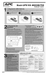
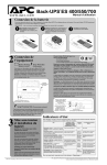
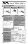
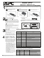
Back-UPS®
1
BR650CI / BR650CI-AS User Guide
Connect Battery
For safety, the Back-UPS is shipped with one battery wire disconnected. The Back-UPS will not operate until the wire is connected to the touch safe battery
terminal.
NOTE: Small sparks may occur during battery connection. This is normal.
2
1
TURN the Back-UPS over, and slide
the battery compartment cover off of
the battery housing.
REMOVE the battery from the battery
compartment, and connect the black wire
to the negative (-) battery terminal. Ensure
the battery is installed as shown below.
2
Connect Equipment
Battery Backup
Plug the Back-UPS power cord directly into a wall outlet, and not to a surge
protector or power strip. The wall outlet should be located near the equipment, and
easily accessible.
These outlets are powered whenever the Back-UPS is switched
ON. During a power outage, or other utility problems (brownouts,
over-voltages), these outlets will be powered for a limited time by
the Back-UPS. Plug your computer, monitor, and two other datasensitive devices (external disk or tape drive) into these outlets.
Surge Protection Only
Power
Switch
These outlets provide full-time protection from surges even if the
Back-UPS is switched OFF. Plug your printer, fax machine,
scanner, or other peripherals that do not need battery power into
these outlets.
Power On
UPS Status Indicator
(Green - OK, Red or AmberSee User Manual)
Connect AC Line Cord
Plug the Back-UPS power cord into a wall outlet, not a surge
protector or power strip. The outlet should be near the equipment
and easily accessible.
3
Press the ON/OFF switch to power the unit
ON.
A single short beep, and the green “Power On”
indicator confirms that the Back-UPS is on and
ready to provide protection.
4
The Back-UPS should charge for at least 24
hours to ensure sufficient runtime. The unit is
being charged whenever it is connected to utility
power, whether the unit is turned ON or OFF.
Transfer Voltage and
Sensitivity Adjustment
(Optional)
In situations where the Back-UPS, or connected
equipment, appears too sensitive to the input voltage, it may be necessary to adjust the transfer
voltage. This is a very simple task that requires
the use of an ON/OFF push button. To adjust the
transfer voltage, perform the following steps:
1. Plug the Back-UPS into the utility power
source. The Back-UPS will be in “Standby
mode” (no indicators are lit).
2. Press the ON/OFF push button fully in for 10
seconds. The Online LED will begin glowing in
a cyclical order: GREEN-AMBER-RED, indicating it is going into “Program mode”.
3. The Back-UPS will then indicate the current
sensitivity, as shown in the Transfer Voltage
and Sensitivity Adjustment table below.
4. To select the LOW sensitivity setting, press the
ON/OFF push button until the LED begins
flashing GREEN.
5. To select the MEDIUM sensitivity setting,
press the ON/OFF push button until the LED
begins flashing RED.
6. To select the HIGH sensitivity setting, press
the ON/OFF push button until the LED begins
flashing AMBER.
7. To exit Programming mode, once sensitivity is
set, wait approximately 5 seconds, and all of
the LED indicators will be off (unlit).
990-2994B Copyright 2007 American Power Conversion Corp.
INSTALL the battery compartment cover
back onto the battery housing.
Place the Back-UPS to avoid:
- Direct sunlight
- Excessive heat
- Excessive humidity or contact with fluids
Surge Protection
Power On
3
Power On
Status Indicators
The Back-UPS ES indicates its operating status using a combination of visual and audible indicators. Use the
following table to identify the status of the Back-UPS ES.
Visual Indications
(Power On - Green)
(Replace Battery - Red)
Audible Indication
(Buzzer)
GREEN On
Off
GREEN On (Off during
4 beeps)
4 beeps repeated
every 30 seconds
On-Battery - Back-UPS is supplying battery power to the load
connected to the Battery outlets.
Flashing GREEN
Constant Beeping
(every 1/2 second)
Low Battery Warning - The Back-UPS is supplying battery power to the
load connected to the battery outlets, and the battery has 1.5 minutes of
battery power remaining.
Alternating
GREEN & RED
Constant tone
Bad Battery Detected - Battery needs to be charged, or is at end of life
and must be replaced (see Replace Battery).
Flashing
RED
Constant tone
Battery Disconnected - The battery is disconnected or it is a bad
battery (see Replace Battery).
Off
Short beep every
4 seconds
Off
Constant Tone
On Battery Overload - Connected equipment requires more power
than provided by Back-UPS battery. Unplug devices one at a time to
remove overload. If not corrected contact APC Technical Support.
GREEN On
Constant Tone
On Line Overload - The power drawn by the connected equipment
exceeds the power capacity of the Battery Backup.
Flashing
RED
Condition
Power On - Back-UPS is supplying conditioned utility power to the
connected equipment.
Low Battery Shutdown - During On Battery operation the battery
power was almost completely exhausted, and the Back-UPS is waiting
for utility power to return to normal.
Chirp every 2 seconds Charger Warning - Back-UPS has experienced an internal problem, but
continues to power the load. Contact APC Technical Support.
Off
Constant Tone
Charger Fault - Back-UPS has an internal problem, and is no longer
powering the load. Contact APC Technical Support.
Alternating
GREEN/AMBER/RED
Off
Button Program Mode - see Section 4, and the table below.
GREEN Flashing
Off
Low Sensitivity Mode - see Section 4, and the table below.
RED Flashing
Off
Medium Sensitivity Mode - see Section 4, and the table below.
AMBER Flashing
Off
High Sensitivity Mode - see Section 4, and the table below.
Transfer Voltage and Sensitivity Adjustment
Indicators
Flashing
Sensitivity
Setting
Input Voltage Range
(For Utility Operation)
Green
Flashing
LOW
155 - 290
Input voltage is extremely low or high.
Not recommended for computer loads.
Red Flashing
MEDIUM
(factory default)
160 -280
Back-UPS frequently goes on battery.
Amber
Flashing
HIGH
165 - 270
Connected equipment is sensitive to voltage
fluctuations.
When to Use
APC, Back-UPS and PowerChute are registered trademarks of American Power Conversion Corp.
All other trademarks are property of their respective owners.
Troubleshooting
Use the table below to solve minor Back-UPS installation or operation problems. Consult APC Online Technical Support or call APC Technical Support for assistance with problems that
cannot be resolved using the table below:
Problem
Problem
Back-UPS will not turn on.
No power at the Surge Protection Only
outlets.
Connected equipment loses power.
Probable Cause
Solution
Circuit Breaker has tripped.
Reduce the amount of equipment plugged into the “Battery Backup + Surge
Protection” outlets. Reset the circuit breaker by pushing it back in.
Battery is disconnected, or utility power is not available at
the wall outlet.
Ensure the fuse or circuit breaker for the wall outlet is okay, and the wall switch
controlling the wall outlet (if any) is in the ON position.
Surge Protection Only outlets are overloaded.
Reduce the number of devices plugged into Surge Protection Only outlets.
Utility power not available at the wall outlet.
Ensure the fuse or circuit breaker for the outlet is not tripped, and the wall switch that
controls the outlet is ON.
The Back-UPS is overloaded.
Ensure the equipment you want to stay powered during a power failure is plugged
into the Battery + Surge Protection” outlets, and NOT the Surge Protection Only
outlets.
Solution
Ensure the equipment plugged into the outlets of the unit are not overloading the
capacity of the unit. Try disconnecting some of the equipment one device at a time,
and see if the problem continues.
The Back-UPS has exhausted its available battery power.
The unit can only operate on battery power for a limited amount of time. The unit will
eventually turn off when the available battery power has been used. Allow the unit to
recharge for 24 hours before continuing to use the unit.
The equipment connected to the Back-UPS does not
accept the step-approximated sine waveform from the unit.
The output waveform is designed for computers and computer-related equipment. It
is not designed for use with motor-type equipment.
The Back-UPS may require service.
Contact APC Technical Support for further troubleshooting.
The Power On indicator is lit, and the unit is
beeping four times every 30 seconds, or it is
emittng a constant tone.
The unit is using battery.
The unit is operating normally and using battery power. Once On Battery, you should
save your current work, power down your equipment, and turn the unit OFF. Once
normal power is restored, you may turn the unit back ON, and power your equipment.
The Power On indicator flashes once per
second, and the Back-UPS beeps once per
second at the same time.
Battery capacity is low (there is about 2 minutes of use
remaining).
The unit is about to shut down due to a low battery charge condition! When the unit
beeps once every second, the battery has about 2 minutes of power remaining.
Immediately power down your computer ,and turn the unit OFF. When power returns
to normal, the unit will recharge the battery.
Inadequate runtime.
The battery is not fully charged.
Battery is near the end of useful life.
Specifications
Item
Input
Safety
Type
Specifications
Voltage
Frequency
230 VAC nominal
50 or 60 Hz ±3 Hz, 50Hz factory default value
Over-voltage Transfer
280 VAC, typical
UPS Capacity (total)
650 VA / 390 W
Voltage On Battery
50 Hz ±1 Hz
Transfer Time
50 Hz: 6ms typical, 10ms maximum
60 Hz: 5ms typical, 8ms maximum
Protection and Filter AC Surge Protection
!
Type (maintenance-free)
Electrical Safety
To reduce the risk of fire, connect only to a circuit provided with 20-amp
maximum branch circuit overturned protection.
CAUTION! De-energizing Safety
The Back-UPS has an internal energy source (the battery); the output may be
energized when the unit is not connected to an AC power outlet.
To de-energize pluggable equipment: switch the unit off. Disconnect the unit
from utility power. Next, disconnect the equipment from the unit.
The unit includes a protective earth conductor that carries the leakage current
from the connected devices. Total leakage current must not exceed 3.5 mA.
Use of the unit in life support applications where failure of the unit can
reasonably be expected to cause the failure of the life support equipment or to
significantly affect its safety or effectiveness is not recommended.
Resettable circuit breaker
12V, 28 Watts
2 - 5 years depending on the number of discharge
cycles and environmental temperature
Typical Recharge Time
Physical
!
Full time, 440 joules
AC Input
Average Life
This equipment is intended for installation in a temperature-controlled indoor area (see
Specifications for exact temperature range), free of conductive contaminants.
230 Vac rms
(step-approximated sine wave)
Frequency - On Battery
Battery
This section contains important instructions that should be followed during Back-UPS
installation and maintenance. The instructions are intended for APC customers who setup,
install, relocate, or maintain APC equipment.
160 ±8% VAC, typical
Brownout Transfer
Output
Allow the unit to charge by leaving it plugged in, and switched on for 24 hours.
Allow the unit to charge by leaving it plugged in, and switched on for 24 hours.
As a battery ages, the amount of runtime available will decrease. Batteries also age
As
a battery ages,
the is
amount
runtime
available
willIf decrease.
also age
prematurely
if the unit
placedofnear
excessive
heat.
the batteryBatteries
will not charge,
the
prematurely
thelonger
unit isoperable,
placed near
heat.
thereplaced.
battery will not charge, the
Back-UPS isifno
andexcessive
the battery
mustIf be
Back-UPS is no longer operable, and the battery must be replaced.
24 Hours
Net Weight
6.7 kg
Dimensions (H x W x D)
12.3 cm (H) x 30.0 cm (W) x 20.4 cm (D)
Operating Temperature
0 oC to 40 oC (32 oF to 104 oF)
Storage Temperature
-15 oC to 45 oC (5 oF to 113 oF)
Operating Relative Humidity
Operating Elevation
!
WARNING! Battery Safety
• This unit contains no user-serviceable parts. This equipment contains
potentially hazardous voltages. Do not attempt to disassemble the unit.
Repairs are only performed by factory trained service personnel.
Batteries must be recycled. Deliver the entire BackUPS to an appropriate recycling facility, or ship it to APC
in the original packaging.
0 to 95% non-condensing
0 to 3000 m (0 to 10,000 ft)
Order Replacement Battery
Replace with an APC qualified battery. Replacement batteries can be ordered from www.apc.com (valid
credit card required). For Back-UPS 650, order APCRBC106 as directed by APC Technical Support.
Warranty
The standard warranty is 2 years from the date of purchase. APC’s standard procedure is to replace the
original unit with a factory reconditioned unit. Customers who must have the original unit back due to
assigned asset tags and set depreciation schedules must declare such a need at first contact with APC
Technical Support. APC will ship the replacement unit once the defective unit is received by the repair
department or cross-ship upon the provision of a valid credit card number. The customer pays for
shipping to APC, and APC pays ground freight transportation costs back to the customer.
Service
Please DO NOT RETURN Back-UPS to the place of purchase under any circumstances.
1. Consult the Troubleshooting section to eliminate common problems.
2. If you still have problems or questions, please contact APC via the internet or at one of the phone
numbers listed below.
3. Before contacting APC, please be sure to record the date purchased, UPS model, and serial number
(on bottom of unit).
4. Be prepared to troubleshoot the problem over the telephone with a Technical Support Representative.
If this is not successful, the representative will issue a Return Material Authorization Number (RMA#)
and a shipping address.
5. Pack the unit in its original packaging. If the original packaging is not available, ask APC Technical
Support about obtaining a new set. Pack the unit properly to avoid damage in transit. Never use foam
beads for packaging. Damage sustained in transit is not covered under warranty (insuring the package
for full value is recommended).
6. Write the RMA# on the outside of the package.
7. Return the unit by insured carrier to the address given to you by APC Technical Support.
• Do not dispose of batteries in a fire. The batteries may explode.
• Do not open or mutilate batteries. They contain an electrolyte which is
toxic and harmful to the skin and eyes.
APC Contact Information
APC Europe
APC Asia Pacific
Mexico
Brazil
Worldwide
Internet
Technical Support
353 91 702000
61 2 9955 9366
292 0253 / 292 0255
0800 555 272
1.401.789.5735
http://www.apc.com
http://www.apc.com/support