1
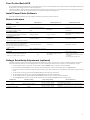
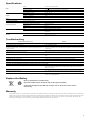
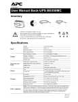
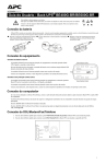
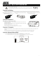
User Guide - Back-UPS® BE600N-BR This unit is intended for indoor use only. Do not operate this unit in direct sunlight, in contact with fluids, or where there is excessive dust or humidity. Connect the Back-UPS power cord directly to a wall outlet. Do not use a surge protector or an extension cord. Connect the Battery The Back-UPS is shipped with one battery cable disconnected. Remove the “Stop! Connect the Battery” label that covers the terminals. Prior to connecting any equipment to the unit, connect the battery cable to the unused battery terminal. Small sparks may occur when the battery cable is connected to the battery terminal. Reinstall the battery compartment cover. Be sure that the release tab locks into place. bu114a bu066b Connect the battery cable securely to the battery terminal. bu064b Press the battery compartment cover release tab located on the rear side of the unit. Slide the battery cover off. Connect Equipment Battery Back-up + Surge Protection outlets Outlets provide protection to connected equipment when the Back-UPS is turned ON and connected to utility power. AVR Overload Check Battery Outlets receive power from the Back-UPS for a limited period of time when a power outage, or brownout condition occurs. Back-UPS Outlets provide protection from power surges or spikes. Surge Protection bu127a Battery Back-up + Connect a computer, monitor and other peripheral devices to the outlets. Connect a Computer If utilizing PowerChute software, connect the supplied data cable to the data port on the rear side of the Back-UPS and to the USB port on the computer. PowerChute software provides automatic file saving and shutdown of a connected computer during a sustained power outage. PowerChute software is an option that can be purchased along with a data cable through the APC Web site, www.apc.com. Connect a Modem/Phone/FAX 1. Use a standard telephone cable to connect the Back-UPS Wall Outlet port to a telephone wall jack. 2. Use a standard telephone cable to connect the Back-UPS Modem/Phone/FAX port to a modem or FAX machine. Data Port 8A 5A Wall Outlet bu128a Modem/Phone/ FAX 1 Turn On the Back-UPS Press the Power ON button located on the top of the Back-UPS. The green LED will illuminate and a single short beep will be audible indicating that the Back-UPS is providing protection for connected equipment. The Back-UPS battery charges fully during the first eight hours while connected to utility power. The Back-UPS battery will charge while the BackUPS is switched ON or OFF. Do not expect full battery run capability during the initial charge time. Install PowerChute Software Install the optional PowerChute CD in the computer and follow the prompts to install the software. Status Indicators Status LED Indicator Audible Indicator On Audible Indicator Off N/A N/A Power On The Back-UPS is supplying utility power to connected equipment. The green LED illuminates. On Battery Back-UPS supplying battery power to battery back-up outlets. The green LED illuminates.The LED is not illuminated during the beeps. Back-UPS beeps four times every 30 seconds. Beeping stops when power transfers back to utility power or the Back-UPS is turned OFF. Low Battery warning The Back-UPS is supplying battery power to the battery back-up outlets and the battery is near a total discharge state. The green LED illuminates with rapid green flashes. The Back-UPS emits rapid beeping, (every 1/2 second). The beeping stops when power transfers back to utility power or the Back-UPS is turned OFF. The red LED flashes. Constant tone Back-UPS is turned Off. Constant tone Back-UPS is turned Off. Check Battery • The battery is disconnected. • The battery needs to be charged, or replaced. Overload Shutdown While on battery power an overload condition has occurred in one or more of the battery The red LED illuminates. back-up outlets while the Back-UPS is operating on battery power. AVR When the AVR feature is activated the amber LED illuminates. N/A N/A The beeping stops when: Sleep Mode While on battery power the battery is completely discharged. The Back-UPS will “awaken” once utility power is restored. N/A The Back-UPS beeps once every four seconds. • Utility power is restored • If utility power is not restored within 32 seconds • The Back-UPS is turned OFF Voltage Sensitivity Adjustment (optional) The Back-UPS detects and reacts to line voltage distortions by transferring to battery back-up power to protect connected equipment. In situations where either the Back-UPS or the connected equipment is too sensitive for the input voltage level it is necessary to adjust the transfer voltage. 1. Connect the Back-UPS to a wall outlet. The Back-UPS will be in Standby mode, no indicators will be illuminated. 2. Press and hold the Power On button for 10 seconds. The red LED flashes, to indicate that the Back-UPS is in Program mode. 3. The green or red LEDs will flash to indicate the current sensitivity level. Refer to the table for an explanation of the transfer voltage sensitivity levels. 4. To select LOW sensitivity, press and hold the Power On button until the green LED flashes. 5. To select MEDIUM sensitivity, press and hold the Power On button until the red LED flashes. 6. To select HIGH sensitivity, press and hold the Power On button until the green and red LEDs flash alternately. 7. To exit Program mode wait five seconds and all LED indicators will extinquish. Program mode is no longer active. LED Flashes Sensitivity Setting Input Voltage Range Recommended Use Green LOW 115 Vac: 88 Vac to 143 Vac 220 Vac: 176 Vac to 264 Vac Input voltage is extremely low or extremely high. Not recommended for computers. Red MEDIUM (factory default) 115 Vac: 88 Vac to 143 Vac 220 Vac: 176 Vac to 264 Vac Use when the Back-UPS frequently switches to battery operation. Alternating Green/Red HIGH 115 Vac: 96 Vac to 137 Vac 220 Vac: 192 Vac to 252 Vac Use when connected equipment is sensitive to voltage fluctuations. 2 Specifications Input Output Voltage 115 Vac or 220 Vac Nominal Frequency 60 Hz + 3 Brownout Transfers 115 Vac: 88 Vac Typical, 220 Vac: 176 Vac Typical Over-voltage Transfer 115 Vac: 143 Vac Typical, 220 Vac: 264 Vac Typical UPS Capacity (6 outlets) 600 VA, 360 W Voltage - On Battery 115 Vac +6%, -10% (step-approximated sine wave) Frequency - On Battery 60 Hz + 1 Transfer Time 5 ms Typical, 8 ms maximum Bivolt Automatic Bivolt 115 Vac: 88-143 Vac, 220 Vac: 176-264 Vac Circuit Breaker Ratings 115 Vac: 8 A, 220 Vac: 5 A Protection and Filter Battery AC Surge Protection Full time, 365 joules Modem/Phone/FAX Surge Protection Single line (2-wire) EMI/RFI Filter Full time AC Input Circuit breaker reset Type Sealed, maintenance-free, lead acid Average Life 2 - 4 years depending on the number of discharge cycles and environmental temperature Net Weight 8 kg (18 lb) Dimensions H x W x D 10 cm x 34 cm x 21 cm 4 in x 10 in x 7 in Physical Troubleshooting Problem and Possible Cause Solution The Back-UPS will not turn on The Back-UPS has not been turned on. Press the Power on button. The Back-UPS is not connected to utility power, there is no utility power available at the wall outlet, or the utility power is experiencing a brownout or over voltage condition. Make sure the power cord is securely connected to the wall outlet, and that there is utility power available at the wall outlet.Where applicable, check that the wall outlet is switched on. Connected equipment loses power A Back-UPS overload condition has occurred. Remove all nonessential equipment connected to the outlets. One at a time reconnect equipment to the Back-UPS. The Back-UPS battery is completely discharged. Connect the Back-UPS to utility power and allow the battery to recharge for eight hours. PowerChute software has performed a shutdown due to a power failure. The Back-UPS is operating normally. The Back-UPS may require service. Contact APC Technical Support for more in depth troubleshooting. The Back-UPS is on, the Check Battery LED flashes and the unit emits a constant tone The battery is disconnected. Refer to the Connect the Battery section in this guide. The Power On LED is illuminated and the Back-UPS beeps four times every 30 seconds The Back-UPS is operating on battery power. The Back-UPS is operating normally on battery power. At this point the user should save all open files, and shutdown the computer. When utility power is restored the battery will recharge. The Back-UPS has an inadequate battery runtime The battery is not fully charged. Leave the Back-UPS connected to utility power for eight hours while the battery charges to full capacity. The battery life cycle is near completion. As the battery ages the runtime capability decreases. To order a replacement battery contact APC at www.apc.com. Replace the Battery Deliver used batteries to a CASC facility. Request that CASC replace the battery with an APC approved battery. Pb Pb Contact APC through the APC Web site www.apc.com, for the location of the nearest CASC facility. Warranty The standard warranty is 2 years from the date of purchase. APC standard procedure is to replace the original unit with a factory reconditioned unit. Customers who must have the original unit back due to assigned asset tags and set depreciation schedules must declare such a need at first contact with APC Technical Support. APC will ship the replacement unit once the defective unit is received by the repair department or cross-ship upon the provision of a valid credit card number. The customer pays for shipping to APC, and APC pays ground freight transportation costs back to the customer. 3 Service If the unit requires service do not return it to the dealer. Follow these steps: 1. Review the problems discussed in Troubleshooting in this manual to eliminate common problems. 2. If the problem persists, contact APC Customer Support through the APC Web site, www.apc.com. a. Note the model number of the unit, the serial number located on the rear side of the unit, and the date purchased. If you call APC Customer Support, a technician will ask you to describe the problem and attempt to solve it over the phone. If this is not possible, the technician will issue a Returned Material Authorization Number (RMA#). b. If the UPS is under warranty, repairs are free. c. Procedures for servicing or returning products may vary internationally. Refer to the APC Web site for country specific instructions. 3. Pack the unit in its original packaging. If this is not available, refer to www.apc.com for information about obtaining a new set. a. Pack the unit properly to avoid damage in transit. Never use Styrofoam beads for packaging. Damage sustained in transit is not covered under warranty. b. Always DISCONNECT THE BATTERY before shipping in compliance with U.S. Department of Transportation (DOT) and IATA regulations. The battery may remain in the UPS. 4. Mark the RMA# on the outside of the package. 5. Return the UPS by insured, prepaid carrier to the address given to you by Customer Support. Contact APC Web site, www.apc.com Telephone support: Toll Free 0 800 555 272; Brazil 11 4689 8600 © 2010 APC by Schneider Electric. APC, the APC logo are owned by Schneider Electric Industries S.A.S., American Power Conversion Corporation, or their affiliated companies. All other trademarks are property of their respective owners. 990-3795B 04/2010