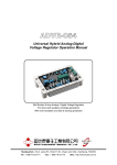
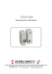
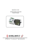
1
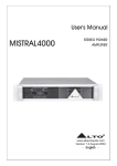
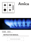
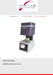
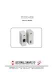
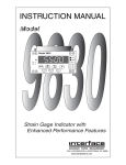
EA63-4
Generator Automatic Voltage Regulator
Operation Manual
Self Excited Automatic Voltage Regulator
Compatible with Basler AVC63-4A*
* Use for reference purpose only and not a genuine Basler product.
Headquarters : No.3, Lane 201, Chien Fu ST., Chyan Jenn Dist., Kaohsiung, TAIWAN
Tel : + 886-7-8121771
Fax : + 886-7-8121775
URL : http://www.kutai.com.tw
1. SPECIFICATION
Sensing Input
Voltage
Frequency
Power Input
Voltage
Frequency
Output
Voltage
Current
Resistance
1 phase 95 ~ 139 VAC ±10% or
190 ~ 277 VAC ±10%
50 / 60 Hz, selectable
95 ~ 139 VAC ± 10%, 1 phase2 wire
50 / 60 Hz
Max. 63 VDC
Continuous 4A
Intermittent 7A for 60 sec
9A for 10 sec
Min. 15 ohm Max. 100 ohm
Voltage Regulation
< ± 1% ( with 4% engine governing )
Voltage Build-up
Residual voltage at AVR terminal > 5 VAC
Thermal Drift
0.05% per °C change in AVR ambient
External Volts Adjustment
± 15% with 10K ohm 1 watt trimmer
EMI Suppression
Internal electromagnetic interference filtering
Unit Power Dissipation
Max. 15 watt
Under Frequency Protection (Factory Setting)
Knee point adjustable range 45 ~ 55 Hz
Over Excitation Shutdown
Field volts shut down after a time delay
If exciter field volts exceed 95 VDC ± 5%
Dimensions
140mm L * 125mm W * 48mm H
Weight
280g ± 2%
V/Hz “CORNER FREQUENCY” SELECTION AND ADJUSTMENT
For 60 Hz systems, the regulator is preset at the factory for a 55 Hz
“corner frequency”. For 50 Hz systems, a 45 Hz “corner frequency” is
achieved by connecting a jumper across terminals Hz1 and Hz2.
The corner frequency can be adjusted by the U/F ADJ rheostat on the
AVR. Clockwise rotation results in raising the corner frequency (shitting
the curve to the right). To set the UF rheostat :
1. Adjuat the UF Rheostat fully CCW.
2. Start the generator and set at rated voltage.
3. Adjust the generator frequency to the desired kneepoint frequency.
Frequency Compensation Curves
Figure 1
4. Slowly adjust the U/F ADJ rheostat clockwise (CW) until the
generator voltage just begins to decrease.
150
140
TIME DELAY (SECONDS)
130
120
110
100
OVEREXCITATION SHUTDOWN
90
80
70
60
50
40
30
20
10
0
80 85 90 95 100 105 110 115 120 125 130 135 140 145 150 155 160 165 170
Overexcitation shutdown is included that removes the output power if
the exciter field voltage exceeds 95 Vdc. If exciter field voltage exceeds
95 Vdc ± 5%, the regulator automatically removes field current, after a
time delay. The time delay is inversely proportional to the magnitude of
the detected overvoltage condition. At 134 Vdc, the field voltage is
removed after approximately 10 seconds. Refer to the following figure.
EXCITER FIELD VOLTAGE (VOLTS)
After output power is removed, the regulator can be reset by
decreasing the input voltage to less than 6 Vac for a minimum of 2
Typical Time Delay Characteristic Curve seconds; this may be accomplished by stopping the prime mover or by
Figure 2
interrupting the regulator input with a reset switch.
______________________________________________________________________________________
2
EA63-4
2. OPERATION PROCEDURE
SWITCH
INITIAL SETTING
2.1 STABILITY ADJUST RHEOSTAT (STAB)
Regulator VAR
Fully CCW
● An internal screwdriver adjustable potentiometer
provides adjustment to the response rate of the
generator output voltage to a change in load.
Remote VAR
Centered
2.4 SYSTEM STAR-UP
● Clockwise rotation of this adjustment provides an
increase in the response time and therefore
decreases the amount of voltage overshoot
(increased stability).Counter-clockwise rotation of
this adjustment provides a decrease in the
response time (faster response time) and
therefore increases the amount of voltage
overshoot (decreased stability).
1. Perform preliminary set-up as described in the
above paragraphs.
2.2 OPERATION
RESULT :
The following system operation procedures provide
instructions for adjusting the EA63-4 voltage regulator.
Symptoms resulting from a faulty regulator and certain
generator system problems are included, together with
suggested remedies.
Voltage should build up. If not, perform Field Flashing.
CAUTION !
Meggers and high potential test equipment must not
be used. Incorrect use of such equipment could
damage the semiconductors contained in the
regulator.
2.3 PRELIMINART SET-UP
1. Verify that the voltage regulator specifications
conform with the generator system requirements.
2. Ensure that the regulator wires are as follows:
● If the remote voltage adjust rheostat is not to be
connected, ensure terminals 6 and 7 are shorted
with a jumper.
● If a 55 Hz “corner frequency” for 60 Hz systems is
desired, ensure that the HZ1 and HZ2 terminals
are open. If a 45 Hz “corner frequency” for 50 Hz
systems is terminals are shorted together with a
jumper.
● For 120V nominal sensing, ensure that terminals
V1 and V2 are not connected. For 240V sensing,
ensure that terminals V1 and V2 are connected
together.
3. Ensure the voltage regulator is
connected to the generator system.
correctly
4. Install the fuses as described in Fuses.
NOTE :
All voltage readings are to be taken with an average
reading voltmeter.
2. Start prime mover and bring up to rated speed.
3. Slowly adjust the regulator VAR CW until the
generator output voltage reaches the nominal
value. If used, adjust the remote VAR to set the
generator voltage to the exact value desired.
RESULT:
Voltage should build up to rated value. If voltage
does not build up to rated value, check generator for
short or excessive load.
4. Check regulator normal operating and loading
conditions.
RESULT:
Voltage regulation should be better than ±1.0%
no-load to full-load. If regulation is not within this
range, perform the following steps:
● Voltage reduction under load may be due to
speed change from no load to full load. causing
the frequency compensation (U/F) circuit to
reduce voltage at lower frequencies.
● Replace voltage regulator.
2.5 OPERATIONAL TEST
1. Connect the test setup as shown in the following
figure, Operational Test. Do not apply power.
Ensure that the light bulb is rated for 120V and is
less that 100W.
Complete the following steps before proceeding
with the system start-up.
5. Set the regulator VAR and external VAR (if used)
as follows:
______________________________________________________________________________________
EA63-4
3
2. Adjust the regulator VAR and/or remote VAR,
and the STABILITY Adjust to maximum CCW.
The following notes () apply to the interconnection
diagrams:
3. Apply 120V, 50/60 Hz power to the regulator.
1. If external pot is not used, short terminals 6 and 7.
The light bulb should illuminate.
4. Slowly adjust the regulator VAR control CW. At
the regulation point, the light bulb should
extinquish. Small adjustments above and below
this level should cause the light bulb goes on and
off rapidly.
5. Rotate the STABILITY ADJ fully CW. Now adjust
the regulator VAR above and below the
regulation point. The light bulb should still to off
and on, but the transition from off to on (and vice
versa) should be much slower than in the
paragraph above.
2. For 50Hz, short terminals HZ1 and HZ2 and
leave open for 60Hz.
3. Item not supplied by KUTAI ELECTRONICS.
4. For 120V Nominal sensing, make no connection
to terminals V1 and V2.
For 240V Nominal sensing, short terminals V1
and V2 together.
5. Select fuses with high interrupting capacity.
3
1
7
EXCITATION
ON-OFF SWTCH
(IF USED)
1
4
R
4 10
12
9
6
R
7
N
5
11
S
2
N
10
T
S
11
8
12
3
T
8
9
5
6
2
3
EXTERNAL
VOLT.ADJ.
RHEOSTAT
10K 1W
3
EXC.
FIELD
5
4
3
F+ F-
EXC.
FIELD
3
2
6
4 E3 V1 V2 E1
EXTERNAL
VOLT.ADJ.
RHEOSTAT
10K 1W
3
1
7
F+ F-
1
5
4
3 E3 V1 V2 E1
4
EA63-4
3
2
6
7
EA63-4
Interconnection Diagram, 127 / 220 V Nominal,
3-phase, 4-Wire
Interconnection Diagram, 277 / 480 V Nominal,
3-phase, 4-Wire
Figure 4
Figure 5
3
EXCITATION
ON-OFF SWTCH
(IF USED)
EXTERNAL
VOLT.ADJ.
RHEOSTAT
10K 1W
T
N
FIELD
S
EXTERNAL
VOLT.ADJ.
RHEOSTAT
10K 1W
3
EXC.
FIELD
4
3
2
F+ F-
3
4
3
3
1
5
F+ F-
1
2
3 E3 V1 V2 E1
EXCITATION
0N-OFF SWITCH
(IF USED)
6
7
EA63-4
4 E3 V1 V2 E1 3
6
7
EA63-4
NOTE : IF GLASE TYPE FUSE IS USED
3
ENCLOSE FOR SAFETY
Interconnection Diagram, 127 / 220 V Nominal,
1-phase, 3-Wire
Operational Test
Figure 6
Figure 7
______________________________________________________________________________________
4
EA63-4