1
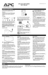
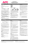
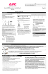
User’s Manual
APC Back-UPS® 300, 500, 650
Inspect
Place
990-2004E Revision 7 12/99
Connect UPS to power
Check site wiring fault
indicator (rear panel-top)
Inspect the UPS and its contents on receipt:
• User’s Manual • UPS • Cord straps (2)
• Telephone cable • Warranty card
• APC Solutions magazine
• Equipment Protection policy
A lit indicator means that a shock hazard exists due to
faulty building wiring , that should be corrected by a
qualified electrician.
5 hours
500 and 650 VA models:
Locate the UPS in a protected area that is free of
excessive dust and has adequate air flow. Do not
operate the UPS where the temperature and
humidity is outside specifications.
• PowerChute® plus software CD
• Interface cable
• Software Install Sheet
If the building wiring fault indicator is lit, one of the
following conditions exist:
• Open or high resistance ground
• Hot and neutral polarity reversal
• Overloaded neutral circuit
Connect the battery
Refer to "Battery replacement procedure"- pg. 2
The packaging is recyclable, save it for re-use or
dispose of it properly. Please fill out the warranty
registration card to obtain warranty coverage.
Note: Improper building wiring will not prevent the
UPS from operating but will limit it's protection
capability. Faulty building wiring could result in
equipment damage that is not covered by APC. Please
refer to APC's Equipment Protection Policy for details.
Charge the battery
The UPS battery charges whenever it is connected to
utility power and typically requires less than five hours
to charge fully. UPS capacity is reduced until the
battery is fully charged.
Connect equipment
Accessory Surge Protection Outlets (500 and 650
VA models only): These outlets are for equipment that
need surge protection but do not need power during a
utility outage (like an inkjet printer or a scanner).
BlockSafe™ Outlets (500 and 650 VA models only):
Corded sockets are provided which accept "block type"
plugs without covering other outlets. Some printers and
external disk drives have block type plugs that look
similar to the one below.
Cord Straps: Straps are provided to keep cords from
tangling and taking up too much space.
Connect phone cables to
surge protection (optional)
Switch "On" and test the UPS
Press the upper portion of the Power 1/0 switch and
then switch "On" the equipment connected to the UPS.
The Power 1/0 switch should be lit. Utility power is
supplied to the equipment.
Socket Location:
Rear panel of 500 and 650 VA models only.
Surge protection is provided for one phone line when
it is connected as shown below:
Perform a simulated utility blackout test to confirm the
UPS unit can switch from utility power to battery
power and back again, without affecting equipment
powered by the UPS.
Phone Line
Connected equipment must be "On".
Battery Back-Up Outlets:
•
•
Surge protection when utility power is used
Battery power and surge protection when utility
voltage is outside acceptable limits.
Data-sensitive equipment such as a computer, monitor,
or external drive are connected to these outlets.
Continued
Start the test by either:
•
•
Continued
Caution: Do not connect a surge
suppressor or laser printer to the UPS.
These devices may overload the UPS.
Unplugging the UPS power cord, or
Pressing and holding the "Test" portion of the Test/
Alarm Disable switch (500 and 650 VA models
only).
Modem/Fax/Phone
System
1. The UPS will then beep once every five seconds (or
continuously) to remind you that your equipment is
powered by a limited capacity power source.
2. Restore power to the UPS by releasing the Test
switch or by reconnecting the UPS power cord.
If the equipment operation was undisturbed throughout
the testing, the system is operating properly.
Connect computer interface cable (optional)
Connect the interface cable to the computer interface
port on the rear panel of the UPS. Connect the other
cable end to an unused serial port socket on the
computer and install the PowerChute® plus software
(see software documentation for detailed instructions).
Socket Location:
Rear panel of UPS
Note: 300 VA model users must purchase software and
cable separately. Call APC at the number listed at the
bottom of Page 2, and ask for software kit AP9015.
UPS Controls
Power 1/0 Switch
1 The UPS operates and all connected devices are
powered.
0 The UPS is de-energized and all devices connected
to battery backup outlets are unpowered
The Power 1/0 Switch controls
power to the UPS.
Test/Alarm Disable Switch
Test
Switch Location: Front panel of
500 and 650 VA models only.
Press the "Test" portion of the Test/Alarm Disable
Switch to simulate a power outage - the UPS battery
supplies power to the equipment
All devices connected to battery back-up outlets can
be switched "On" or "Off" using this switch, if each
device's power switch is left in the "On" position.
Lamp: The lamp in the Power 1/0 Switch is lit
whenever normal utility voltages are present at the
power sockets.
Note: Accessory surge protected outlets are
unaffected by this switch - they remain powered as
long as utility power is available.
Specifications
The UPS will emit a beep once every five seconds
during a utility power outage, unless the alarm is
disabled by pressing this side of the switch. The UPS
low battery warning (a loud continuous tone) will still
sound in the event of an extended utility outage.
The battery run time can be checked by pressing and
holding the "Test" switch and waiting to see how long
the UPS provides power to the equipment before the
low battery warning is sounded.
RunTime (minutes) vs. Power Demand
Acceptable Input Voltage
0 - 150 V ac, Single Phase
Transfer Voltage
103 V ac (may be set lower)
Output Voltage
Alarm Disable
109-121 V ac
System Description
Demand
(Watts)
Back-UPS
300
Back-UPS
500
Back-UPS
650
Desktop 486
w/14" or 15" Monitor
105
16
22
37
110
14
20
34
Input Over Current Protection
Resettable circuit breaker
Frequency Limits (on line)
57 - 63 Hz (autosensing)
Desktop/Mini Tower Pentium
w/14 or 15" Monitor
Transfer Time
(blackout response time)
8 ms
Desktop/Mini Tower Pentium
w/17" Monitor
130
10
17
26
Desktop/Mini Tower Pentium II/Pentium Pro
w/14 or 15" Monitor
130
10
17
26
Tower Pentium II/Pentium Pro
w/14" or 15" Monitor
150
8
14
21
Tower Pentium
w/17" Monitor
150
8
14
21
Desktop/Mini Tower Pentium II/Pentium Pro
w/17" Monitor
150
8
14
21
Desktop/Mini Tower Pentium
w/21" Monitor
170
6
12
17
Tower Pentium II/Pentium Pro
w/17" Monitor
170
6
12
17
Desktop/Minitower K6
w/21" Monitor
180
6
10
15
Maximum Load
On-batter y Output Voltage
300 VA - 180 W
500 VA - 330 W
650 VA - 400 W
115 V ac
On-batter y Frequency
58-62 Hz unless synchronized to utility during brownout
On-batter y Waveshape
Stepped sine-wave
Output Over Current Protection
Batter y Type
Typical Batter y Life
Overcurrent and shor t-circuit protected, latching shutdown on
overload
Spill proof, maintenance free, sealed lead-acid
3 to 6 years, depending on number of discharge cycles and
ambient temperature
Typical Recharge Time
5 to 10 hours from total discharge
Operating Temperature
32 to 104° F (0 to 40° C)
Storage Temperature
5 to 113° F (-15 to 45° C)
Tower Pentium
w/21" Monitor
190
-
9
14
Operating and Storage Relative
Humidity
0 to 95%, non-condensing
Desktop/Mini Tower Pentium II/Pentium Pro
w/21" Monitor
190
-
9
14
Tower Pentium II/Pentium Pro
w/21" Monitor
210
-
7
11
Operating Elevation
0 to +10,000 ft (0 to +3,000 m)
Storage Elevation
0 to +50,000 ft (0 to +15,000 m)
Audible Noise at 3 ft (1 m)
Size (H x W x D)
<40 dBA
300 VA, 500 VA: 6.0" x 3.4" x 13.1" (15.1 x 8.6 x 33.3 cm)
650 VA: 6.6" x 4.7" x 14.2" (16.8 x 11.9 x 36.1 cm)
Weight
300 VA 13.1 lb (6.0 kg)
500 VA 15.4 lb (7.0 kg)
650 VA 23.0 lb (10.5 kg)
Shipping Weight
300 VA 15.7 lb (7.1 kg)
500 VA 18.0 lb (8.2 kg)
650 VA 26.5 lb (12.0 kg)
Listing and Cer tifications
EMI Verification
Electromagnetic Immunity
UL 1778, CSA 107.1, FCC par t 15 and par t 68
FCC Class B cer tified
IEC 801-2, 801-3, 801-4 level IV, and 801-5 level III
Note: These values are approximate. Batter y age, excessive use, and elevated operating temperature may
fur ther decrease UPS runtime. More information can be found at http://www.apc.com/sizing.
Option Switches
Order replacement battery
A set of 4 switches, located on the rear panel, can be used to change how the UPS operates. For typical
applications, all switches are in the down position as shown below.
The table below shows the APC part numbers for APC Back-UPS replacement battery cartridges (RBCs).
Replacements can be ordered from local retailers, APC, or the APC website at
http://www.apc.com.
Switch 1
300 and 500 VA models
RBC2
650 VA model
RBC3
Battery replacement procedure
Switch Position
Result
Normal Setting: The UPS beeps once ever y five seconds when the
utility voltage has fallen outside acceptable limits.
If switch #1 is set to the "On" position, the UPS audible utility failure
alarm is defeated. This feature is convenient when brief power
interruptions are common and the alarm becomes annoying.
This procedure requires a coin or screwdriver.
Note: Please read the cautions in the APC Safety Information Guide first!
Battery replacement is a safe procedure, isolated from electrical hazards. You may leave the UPS connected to
utility power and your equipment connected and "On" during this procedure.
Note: Once the battery is disconnected, the loads are not protected from power outages.
Regardless of the position of switch 1, the UPS will sound a loud continuous tone during low battery
conditions.
1. Lay the UPS on its left side. Remove the two screws
holding on the battery door and open the door.
Switches #2 and #3
Note: It may be necessary to pull the battery door slightly
outward or toward the front of the unit in order to open
the door fully.
Switches #2 and #3 set the utility voltage value (transfer voltage) at which the UPS will switch to battery
power. If you know that your equipment will operate properly at any of the voltages less than 103 V shown in
the table, you can change to the corresponding switch positions. Changing the transfer voltage is desirable
when frequent line voltage excursions or line voltage distortion cause the UPS to use battery power too often.
Switch Position
Transfer Voltage
103 V AC
Normal Setting
2. Grasp the white tab attached to the battery and gently pull
the battery out.
3. Disconnect the two wires connecting the battery to the
UPS. Loosen the wires by wiggling them while pulling
straight back from the battery connector.
98 V AC
93 V AC
4. Connect the new battery in place of the old.
88 V AC
Note: Small sparks at the battery connections are normal
during connection.
5. Insert the new battery in the UPS. Carefully avoid
pinching the wires.
Switch #4 (500 and 650 VA models only)
Switch Position
Result
6. Close the battery compartment door and replace the
screws.
Normal Setting: Two minutes prior to shut down during an extended
power outage, the UPS will sound the low battery warning and activate
the low battery signal at the computer interface por t.
7. Spent batteries must be recycled. Deliver the battery to an
appropriate recycling facility or ship it to the supplier in
the new battery's packing material. See the new battery
instructions for more information.
Same behavior as "Normal" except the warning is issued five minutes
before shutdown. Use this setting if you require more than two minutes
to save files and close operations.
Troubleshooting
Storage
Use the table below to solve minor UPS installation problems. Consult the APC web site or contact APC
Technical Support Staff for assistance with complex UPS problems.
Before storing, charge the UPS for at least 10 hours. Store the UPS covered and upright in a cool, dry
location.
Possible Cause
Procedure
UPS beeps about every five seconds
Utility power outage.
None. The UPS is protecting your equipment. Be
prepared to properly exit applications and the operating
system, and then power "Off" the system before the UPS
is seriously discharged.
None. The UPS is protecting your equipment.
UPS operates on-battery although normal utility voltage exists
UPS input circuit breaker "tripped".
Reduce equipment power demand by
unplugging equipment from the UPS.
Reset the circuit breaker (on back of
UPS) by pressing plunger back in.
A brownout has occurred.
The transfer voltage can be lowered by changing option
switches 2 and 3 (see previous section). Note: If you
decide to lower the transfer voltage make sure all
devices connected to battery back up outlets will operate
properly at this lower utility voltage.
UPS will not turn "On"
UPS is not connected to AC power
supply.
Check that the power cable from the UPS to the power
supply is securely connected.
UPS circuit breaker "tripped".
Reduce the power demand on the UPS by unplugging
equipment and reset the circuit breaker.
Very low or no utility voltage.
Check the AC power supply to the UPS
with a table lamp. If the lamp is very
dim, have the utility voltage checked.
Battery is not connected properly.
Storage Temperature
Recharge Frequency
Charging Duration
5 to 86oF (-15 to 30 o C)
Ever y 6 Months
10 Hours
86 to 113oF (30 to 45o C)
Ever y 3 Months
10 Hours
Service
UPS beeps occasionally
Temporary utility outage or
disturbance.
Long term storage
Note: If the UPS requires service, do not return it to the dealer! The following steps should be taken.
1. Consult the Troubleshooting section to eliminate common problems.
2. Verify that no circuit breakers are tripped. A tripped circuit breaker is the most common UPS problem!
3. If the problem persists, consult the APC Worldwide Web site (www.apc.com) or call customer service.
• Record the model number of the UPS, the serial number, and the date purchased. Be prepared to
troubleshoot the problem over the telephone with a technician If this is not successful, the technician
will issue a Return Merchandise Authorization Number (RMA#) and a shipping address.
• If the UPS is under warranty, repairs are free. If not, there is a repair charge.
4. Pack the UPS in its original packaging. If the original packing is not available, ask customer service about
obtaining a new set. Pack the UPS properly to avoid damage in transit.
Note: Never use Styrofoam™ beads for packaging. Damage sustained in transit is not covered
under warranty (insuring the package for full value is recommended).
5. Write the RMA# on the outside of the package.
6. Return the UPS by insured, prepaid carrier to the address given to you by customer service.
APC contact information
Check the battery connections. Consult the Battery
Replacement Procedure that shows how to access the
battery.
USA/Canada ………........……
M ex i c o … … … … . . . . . . . . … … . .
Brazil …………….........……
Worldwide ……........……….…
UPS does not provide expected backup time
The UPS is overloaded.
Unplug non-essential equipment, such as printers.
The UPS battery is weak due to
recent outage or is near the end of
its service life.
Charge the battery. Battery capacity decreases with
frequent (or long) power outages or when operated at
elevated temperatures. If the battery is near the end of its
service life, consider replacing the battery.
Warranty
Customers may return their defective unit to APC for replacement or repair during the standard 2 year
warranty period. APC's standard procedure will be to replace the original unit with a factory-reconditioned
unit. Customers who must have the original unit back due to assigned asset tags and set depreciation
schedules must declare such a need at first contact with APC Customer Service. APC will ship out the
replacement unit once the defective unit has been received by the repair department. The customer pays for
the shipping to APC, APC covers ground freight transportation costs back to the customer.
Internet
E-Mail
http://www.apc.com
[email protected]
1-800-800-4272
292-0253, 292-0255
0800-12-72-1
1-401-789-5735