1
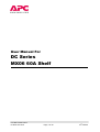
User Manual For
DC Series
MX06 60A Shelf
User Manual 990-9189A
DC MX06 60A Shelf
Page 1 of 30
th
18 FEB 02
DC MX06 60A Shelf
The DC Series MX06 60A Shelf is a 19”
compatible modular power plant capable
of supplying up to 63A at –48V DC (54V).
The unit contains a simple alarms/control
card that can configure up to 6 x 10.5A
rectifiers and offers voltage control and
basic alarms. Optional mounting brackets
are offered to allow the system to be fitted
in a 23” rack. Easy sub-assembly access
and replacement allows for convenient
and efficient maintenance.
Applications
Features
n Cellular and PCS
n Hot Plugable Fan Cooled Units
n Distributed Networks
n Form C relay signals and visual
alarms
n PABX
n Single or 3-phase versions available
with a wide Input voltage range
n Customer premises
n Industrial
n Battery temperature compensation
of charging voltage
n Microwave
n Broadband Wireless
n Overvoltage and reverse voltage
protection
n Fibre
n 3600W Output Power
User Manual 990-9189A
DC MX06 60A Shelf
Page 2 of 30
th
18 FEB 02
Contents
SECTION
1
2
DESCRIPTION
General Information
1.1
Introduction
1.2
Safety Precautions
1.3
Types Of Hazard
1.4
Inspection Of Goods
1.5
APC Worldwide customer support
1.6
Warranty Information
Product Overview + Technical Description
2.1
Specification
2.2
2.3
2.4
2.5
3
User Manual 990-9189A
DC MX06 60A Shelf
2.1.1
Rectifier
2.1.2
System AC Input
2.1.3
System Output
2.1.4
Environmental
2.1.5
Approvals
LED’s
2.2.1
4 LED Rectifier
2.2.2
Single LED Rectifier
Alarms/Customer Inputs
2.3.1
System Alarms
2.3.2
Individual Rectifier Alarms
System Set-up Options
2.5.1
Current Limit Programming
2.5.2
Enable Function
2.5.3
Temperature Compensation
Mechanical
2.5.1
Dimensions
2.5.2
Weight
2.5.3
Mounting Options
System Configuration
Page 3 of 30
PAGE
5
5
5,6
6
7
8
9
10
10
10
10
11
11
11
11
11
11
12
12
13
14
14
14
15
16
16
16
17
18
th
18 FEB 02
4
Installation Procedure
4.1
AC Primary Input
4.2
4.3
4.4
5
6
7
8
4.1.1
Single Phase
4.1.2
Single Phase, AB Feed
4.1.4
3 Phase Star
4.1.5
3 Phase Delta
System Output Connection
System Earthing
4.2.1
Output Earth
4.2.2
Alarms Earth
Cable Routing
4.4.1
Input Cables
4.4.2
Output Cables
Commissioning the System
5.1
General
5.2
Powering up the MX06 60A Shelf
Manual Handling Procedure
6.1
General
6.2
Preparation
6.3
Method
Fault Finding / Symptoms
7.1
Warnings
7.2
Fault Symptoms
Service, Accessories & Spares
8.1
Rectifier Replacement
8.2
Alarm Module Replacement
19
19
19
20
21
22
23
24
24
24
25
25,26
26
27
27
27
28
28
28
28
29
29
29
30
30
30
Issue Record
ISSUE
DESCRIPTION
REV01
New document
REV02
Update
User Manual 990-9189A
DC MX06 60A Shelf
Page 4 of 30
DATE
APPROVED
7th JAN 2002
YES
18th FEB 2002
YES
th
18 FEB 02
1 General Information
1.1 Introduction
DC Power Plants from APC have unique features that make them easy to install, maintain, and upgrade.
The rectifier units are modular and truly “hot-pluggable” into the shelf assembly without any separate ac
wiring.
All system settings are controlled from the system control unit that provides monitoring and control
functions for each component of the system as well as alarm outputs for system diagnosis and
maintenance.
The APC international network of sales and service offices and qualified representatives provides sales
assistance for proposals, purchases, and after-sales support.
1.2 Safety Precautions
The unit must be installed into an enclosure which conforms to the requirements of EN60950 : 2000,
rd
CAN/CSA 22.2 # 60950-00, UL60950 3 Edition and be connected to comply with the standard. This
includes but is not limited to providing external disconnection devices.
The end use equipment must be installed in accordance with the local building code and practices, by
proper licensed installation personnel, taking into consideration all cautions and requirements detailed in
this manual.
For proper guidance on the selection of any external disconnects and cabling requirements see the CEC
and NEC codes or the local electrical code of the country of installation.
Before using the power system, carry out the following:
1.2.1
READ AND FOLLOW THE SAFETY PROCEDURES.
1.2.2
REFER TO THE FOLLOWING DOCUMENTS. ALL PROCEDURES MUST BE
CARRIED OUT IN ACCORDANCE WITH THE INSTRUCTIONS THEREIN.
•
EN60950 : 2000, CAN/CSA 22.2 # 60950-00, UL60950 Third Edition.
•
MANUFACTURER’S INSTRUCTIONS
•
MATERIAL SAFETY DATA SHEET (MSDS) FOR THE BATTERY
(If batteries are supplied with the system)
•
HEALTH AND SAFETY AT WORK ACT, 1974 (UK)
•
OCCUPATIONAL SAFETY & HEALTH STANDARDS (OHSA) (USA)
•
ELECTRICITY AT WORK ACT, 1989 (UK)
•
NFPA 70 NATIONAL ELECTRICAL CODE (USA)
User Manual 990-9189A
DC MX06 60A Shelf
Page 5 of 30
th
18 FEB 02
•
CEC Code C22.1-98 ( Canada )
•
CONTROL OF SUBSTANCES HAZARDOUS TO HEALTH (COSHH) REGS
•
MANUAL HANDLING REGULATIONS, 1993 (See Section 6)
1.2.3
BECOME FAMILIAR WITH THE HAZARDS ASSOCIATED WITH THE POWER
SYSTEM AS DETAILED IN PARA 2.
1.2.4
CAUTION - BEFORE INSTALLING RECTIFIERS (POWER SUPPLIES) INTO
AN UNPOPULATED SYSTEM SEE INSTALLATION INSTRUCTIONS IN
SECTION 4.
1.3 Types of Hazards
The following hazards are present in the power system:
•
ELECTRICAL VOLTAGE
•
ELECTRICAL ENERGY
•
HEAVY MASS
POTENTIALLY LETHAL VOLTAGES AND SOURCES OF HIGH ENERGY ARE PRESENT WITHIN
THE POWER SYSTEM. EXTREME CAUTION MUST BE OBSERVED AT ALL TIMES. ACCESS TO
THE INTERIOR OF THE SYSTEM FOR INSTALLATION, COMMISSIONING, MAINTENANCE AND
REMOVAL AND REPLACEMENT PURPOSES IS LIMITED TO FULLY TRAINED SERVICE
PERSONNEL ONLY. THIS SHOULD BE DONE WITH ALL POWER SOURCES DISCONNECTED
EXCEPT WHEN ABSOLUTELY NECESSARY.
User Manual 990-9189A
DC MX06 60A Shelf
Page 6 of 30
th
18 FEB 02
1.4 Inspection upon Receipt of Goods
1.4.1
General
APC has taken precautions in packing the power equipment for shipment to ensure its safe arrival;
however, the entire shipment including any boxes or crates should be inspected upon receipt for
evidence of damage that may have occurred during transit.
1.4.2
Visible External Damage
It is the responsibility of the person receiving the shipment to inventory and inspect all materials against
the bill of lading or waybill provided IMMEDIATELY upon taking delivery while the carrier representative
is still on site. Please be sure that all items are accounted for, including the correct number of pallets
and the quantity of accessory and/or component boxes. Also, note any visible external damage that
may have occurred during transit.
If damage has occurred or the quantity of items is not correct, then:
1)
2)
1.4.3
Make a descriptive notation on the delivery receipt before signing.
File a damage or shortage report with the carrier that delivered the shipment.
Concealed Damage
It is the customer’s responsibility to unpack the power system and equipment received from APC and
check for concealed damage. Within 15 days of receipt, check the materials received against the
detailed packing list to verify that the quantity and condition are complete and satisfactory.
Again, note any damage to the internal packing material and/or material shortages. If damage or
shortage is noted, then:
3) Request an inspection by the carrier
4) File a concealed damage claim; and/or
5) File a material shortage claim with your APC representative.
DELAY IN NOTIFYING THE CARRIER MAY RESULT IN LOSS OF RIGHT TO REIMBURSEMENT
FOR DAMAGES OR LOSS.
If you are unsure about the appearance of a part while conducting the materials inventory and
inspection, refer to the manual or contact the Customer Service Department of APC.
Should you have any questions concerning potential damages or should you experience a lack of
cooperation from your carrier, please contact your APC representative, or call APC.
1.4.4
Return of Damaged Goods
Should equipment be damaged and require return to APC for repair, the APC service representative will
provide instructions along with a valid returned material authorization (RMA) number to facilitate return
of the damaged goods to the APC repair center.
It is important that the steps outlined in Section 1.4.2 and also Section 4 and 5 are followed carefully.
Your APC representative will assist you, if required, in obtaining proper disposition of an initial delivery
return issue; however, a valid RMA number must be obtained before returning any equipment to APC.
User Manual 990-9189A
DC MX06 60A Shelf
Page 7 of 30
th
18 FEB 02
1.5 APC Worldwide Customer Support
Customer support for this or any other American Power Conversion (APC) product is available at no
charge in any of the following ways:
l
Visit the APC web site to find answers to frequently asked questions (FAQs), to access
documents in the APC Knowledge Base, and to submit customer support requests.
http://www.apc.com (Corporate Headquarters)
Connect by links to APC web pages for specific countries and regions, each of which provides
customer support information.
http://www.apc.com/support/
Submit customer support requests.
l
Contact an APC Customer Support centre by telephone or email.
Regional Centres:
APC Headquarters (US and Canada)
(1) (800) 800 4272 (toll free)
[email protected]
Latin America
(1) (401) 789 5735 (United States)
[email protected]
Europe, Middle East, Africa
(353) 91 702020 (Ireland)
[email protected]
Local, country-specific centers: go to http://www.apc.com/support/contact for contact
information.
Contact the APC representative or other distributor from whom you purchased your APC
product for information on how to obtain local customer support.
User Manual 990-9189A
DC MX06 60A Shelf
Page 8 of 30
th
18 FEB 02
1.6 Warranty Information
1.6.1
Limited Warranty
American Power Conversion (APC) warrants the DC Series MX06 60A Shelf to be free from defects in
materials and workmanship for a period of two years from the date of purchase. It’s obligation under this
warranty is limited to repairing or replacing, at it’s own sole option, any such defective products. This
warranty does not apply to equipment that has been damaged by accident, negligence, or
misapplication or has been altered or modified in any way. This warranty applies only to the original
purchaser.
1.6.2
Warranty Limitations
Except as provided herein, American Power Conversion makes no warranties, express or implied,
including warranties of merchantability and fitness for a particular purpose.
Some jurisdictions do not permit limitation or exclusion of implied warranties; therefore, the aforesaid
limitation(s) or exclusion(s) may not apply to the purchaser.
Except as provided above, in no event will APC be liable for direct, indirect, special, incidental, or
consequential damages arising out of the use of this product, even if advised of the possibility of such
damage.
Specifically, APC is not liable for any costs, such as lost profits or revenue, loss of equipment, loss of use
of equipment, loss of software, loss of data, costs of substitutes, claims by third parties, or otherwise.
This warranty gives you specific legal rights and you may also have other rights, which vary from state to
state.
User Manual 990-9189A
DC MX06 60A Shelf
Page 9 of 30
th
18 FEB 02
2 Product Overview and Technical Description
2.1 Specification
2.1.1
Rectifier
Parameter (per rectifier)
1TWF0500H54**
Approved Input Rating
I/p Operating Range
RMS Input Current
“
“
“
Approved Input Frequency
range
Turn-on Surge
Turn-on Time
Internal Fuse
Power Factor
Output Voltage (Nominal)
O/p Current (Rated)
115V or 230Vac
103.5V to 264V
6.5A max @115V
3.6A max @230V
45 – 65Hz
Current Limit
Over Volts Protection
Power O/p (Rated)
Efficiency
Cooling
Ambient Temp
< 10A
< 2 Seconds
7 amp 250V time lag
99 % typical, 90 % min
54.5V dc
10.5A @ 230V, 0-50°C
9A @ 230V, 50-65°C
9A @ 115V, 0-50°C
8A @ 115V, 50-65°C
105 % of rated
59.5V dc ± 0.5V
500W @ 115V
600W @ 230V
83 % typical
Fan Cooled, front to rear
-40 to 50°C (de-rate above 50°C)
Note :- See TWF0500 Rectifier datasheet for further or more detailed information
2.1.2
System AC Input
Input Voltage (Single phase)
(3 Phase Star)
(3 Phase Delta)
RMS Current (max) single phase
RMS Current (max) 3 phase star
RMS Current (max) 3 phase delta
Frequency
Efficiency
Harmonic Distortion
User Manual 990-9189A
DC MX06 60A Shelf
90 - 264Vac (Live to Neutral)
208Vac, 380Vac, 400Vac or 415Vac (phase to phase)
208Vac only (phase to phase)
39A @ 115V ±10%, 22A @ 230V ±10% (total)
13A @ 208Vac, 7.2A @ 415Vac (per phase)
12.5A @ 208Vac (per phase)
45 – 65 Hz
83% Typical
Complies with EN61000-3-2
Page 10 of 30
th
18 FEB 02
2.1.3
System Output
Output Voltage Nominal
Voltage Adjustment Range
Current Rating
Temperature Coefficient
Current Limit
Reverse Quiescent Current
Regulation
Over voltage
2.1.4
Environmental
Temperature Range
Humidity
2.1.5
54.5Vdc
44 V – 57 V
63 A @ 230Vac, 54 A @ 115Vac, 42A @ 100Vac
-76mV/°C ±10% (over range 0°C - 50°C)
100% - 110% of Rated Current
Less than 100mA, Typically 50mA
250mV max for any line or load condition
59.5V ± 0.5V (reset by interruption of AC Input)
-25°C to 65°C operating range (De-rate above 50°C)
See section output current ratings section 2.1.1 for
per rectifier de-rating detail
85% non condensing
Safety Approvals
Approved to the following
CE marked to the European Low Voltage
Directive 73/23/EEC amended by 93/68/EEC
complies with BS EN60950:2000
Certified to CAN/CSA 22.2#950-00 (NRTL/C
UL1950 3rd Edition)
2.2 LED’s
2.2.1
4 LED Rectifier
Rectifier LED’s
2.2.2
Input Healthy
Output Healthy
Current Limit
Overvoltage
Green
Green
Red
Red
Rectifier Fail
Red
Single LED Rectifier
Rectifier LED
NB/ LED’s are lit when description is true.
User Manual 990-9189A
DC MX06 60A Shelf
Page 11 of 30
th
18 FEB 02
2.3 Alarms + Customer Inputs
To monitor the system status a selection of alarm outputs are available. Each rectifier has 4 front panel
LED’s giving a visual notification of a system fault. There is also a range of open collector transistor
alarm outputs and a set of form C relay contacts that can be accessed at the rear of the shelf.
Below is a list of the available alarms along with their function and pin number.
2.3.1
System Alarms/Inputs
All the system alarms are available from the 26way ribbon connector (SK4) mounted on the alarms card.
The alarms and inputs are listed below.
Alarm/Input
Pin
Description
V Trim
SK4-13
+ Sense
- Sense
Rectifier Fail
SK4-17
SK4-15
SK4-11
AC Input Fail
SK4-24
AC Input Healthy
SK4-8
Common
SK4-10
Enable
SK4-19
5V
SK4-18
Current Share
Fan Fail
SK4-12
SK4-9, SK4-1
This pin floats at 2.5V (O/P @ 54.5V) nominal with respect to
negative sense (SK4-15).
Applying a DC voltage adjusts the output by –1V/V.
(For 1V swing on program pin the output voltage changes by –1V)
Bussed through sense pins from rectifiers.
Bussed through sense pins from rectifiers.
N/C relay contact bussed through from rectifier. Contact is closed
on fail
Relay contact on daughter board. Contact closed when input
supply fails.
Relay contact on daughter board. Contact closed when input
healthy.
Common for all signals (unless stated otherwise). Signal common
and relay commons connected together
Connects to SK29-2 (back-plane). To enable system output either
fit link from SK29-2 to SK29-3 (-Ve O/p) or connect SK4-19
(enable) to SK4-15 (-Ve Sense)
From internal rectifier rail. Low current capability supply to be
connected to Vtrim, to program down output volts.
Use for paralleling purposes only
Opto isolated open collector transistor output (rated at 60Vdc
@20mA). Pulls low when one or more rectifier fans fail (not
available if system fitted with Single LED Rectifiers).
The relay contacts are rated as follows:
AC Rating
DC Rating
-
0.5A @ 125Vac
1A @ 24Vdc
Max VDC
-
0.6A @ 110Vdc
User Manual 990-9189A
DC MX06 60A Shelf
SK4
Page 12 of 30
th
18 FEB 02
2.3.2
Individual Rectifier Alarms
In addition to the system alarms and inputs, six alarm connectors are mounted on the backplane board.
Each one of these connectors offers six alarms/inputs for a particular rectifier. This means the end user
can, if required, monitor each rectifier fitted separately as well as the system as a whole.
SK19 = Rectifier 1
SK20 = Rectifier 2
SK21 = Rectifier 3
SK22 = Rectifier 4
SK23 = Rectifier 5
SK24 = Rectifier 6
Alarm
All Sockets
Description
Over Temp
Pin 1
Marginate
Pin 2
D.C Healthy
Pin 3
I Analogue
Pin 4
Over Volts
Pin 5
Common
Current Limit
Pin 6
Pin 7
Open collector opto output is pulled low when unit has
shut down due to over temp conditions. Alarm has 20mA
current capability (not available if system fitted with Single
LED Rectifiers).
Link the marginate pin to +Ve output or +Ve Sense to
reduce the output voltage by 2.4V. When link removed the
output will return to nominal.
Opto signal is open collector pulled low when output
healthy (31V-60V). Current capability is 20mA
This is an analogue voltage proportional to output current.
Full load (10.5A) is represented by a voltage of 5Vdc
Open collector opto output pulled low when output trips
due to over volts. Has a 20mA current capability (not
available if system fitted with Single LED Rectifiers).
Reference point for all of the alarms
Open collector opto output pulled low when in current limit.
Has a 20mA current capability (not available if system
fitted with Single LED Rectifiers).
SK24
SK23
User Manual 990-9189A
DC MX06 60A Shelf
SK22
SK21
Page 13 of 30
SK20
SK19
th
18 FEB 02
2.4 System Set-up options
2.4.1
Current Limit Programming
The system output current limit can be set to either the standard “High” (100%) level or “Low” (70%)
level by using SK30.
For “High” current limit level link pins 1 and 2
For “Low” current limit level link pins 2 and 3
Selecting “Low” current limit level will program down each rectifiers current limit level to roughly 70% of
the default level. (See section 2.1.1 for default levels).
System is set to “High” current limit as standard.
2.4.2
Enable Function
The system can be set to either “Local” or “Remote” Enable by using SK29.
For “Local” enable link SK29 pins 2 and 3 with supplied link.
For “Remote” enable link SK29 pins 1 and 2 with supplied link.
If “Remote” enable SK4-19 and SK4-10 must be linked to enable rectifier outputs.
System is set to “Local Enable” as standard.
Remove rear cover
to leave view shown
SK30
SK29
User Manual 990-9189A
DC MX06 60A Shelf
Page 14 of 30
th
18 FEB 02
2.4.3
Temperature Compensation
Temperature compensation / Fixed output voltage selection (SK1)
For “Fixed Output Voltage” SK1-1 to SK1-2 will be linked. (default setting)
For “Temp Comp” remove above mentioned link and fit supplied thermistor kit to SK1.
Temperature compensation uses the thermistor to monitor battery temperature and automatically
adjusts the output voltage of the system. This ensures the charging voltage stays within the battery
manufacturers recommended limits.
If temperature compensation is
enabled the output will be as follows:
Nominal Output: 54.5Vdc @ 25°C
Temp coefficient: -76mV/°C ±10%
SK1
Pin 3
Pin 2
Pin 1
DC MX06 60A Calculated Temperature Compensation (54V)
59.00
58.00
Voltage (V)
57.00
Output Voltage max
Output Voltage nom
56.00
Output Voltage min
Minimum Battery Voltage
55.00
Maximum Battery Voltage
54.00
53.00
52.00
-10.00
0.00
10.00
20.00
30.00
40.00
50.00
60.00
70.00
Temperature (°C)
User Manual 990-9189A
DC MX06 60A Shelf
Page 15 of 30
th
18 FEB 02
2.5 Mechanical
2.5.1
Dimensions
Dimension
Length
2.5.2
A
482.6mm
(19in)
B
132.5mm
(5.22in, 3U)
C
283.6mm
(11.17in)
D
82.5mm
(3.25in)
E
138.5mm
(5.45in)
F
438.2mm
(17.25in)
Weight
Item Measured
Empty Shelf
Single Rectifier
Full System
Weight (Kg)
5.2
1.75
15.70
Weight (lbs)
11.5
3.85
34.55
User Manual 990-9189A
DC MX06 60A Shelf
Page 16 of 30
th
18 FEB 02
2.5.3
Mounting Options
The DC MX06 60A Shelf has 3 positions for mounting ears. If mounting ears were ordered with the
system they will be fitted in the front position as standard. The 2 alternative mounting positions are
shown below. The end user can simply unscrew the ears and re-fit in the desired position.
Ensure all screws are re-tightened sufficiently.
Mounting Ears
Optional Mounting
Positions
User Manual 990-9189A
DC MX06 60A Shelf
Page 17 of 30
th
18 FEB 02
3 System Configuration
The MX06 60A shelf is designed to meet a range of customer requirements/applications. A number of
options are available including alternative input supply configurations, 19 and 23 inch mounting versions
and temperature probes etc.
Contact APC for details.
Alternatively the following pre configured system is available:
DCM00K04W481
Rear access 60A system with a single phase–single feed input configuration including alarms card, 19”
mounting brackets, 4 rectifier blanking panels and a non-temperature compensated output voltage of
54.5Vdc. Probe for temperature compensation supplied.
User Manual 990-9189A
DC MX06 60A Shelf
Page 18 of 30
th
18 FEB 02
4 Installation Procedure
4.1 AC Primary Input
4.1.1
Single Phase, Single Feed
To connect the input supply to the DC MX06 60A Shelf proceed as follows:
•
The AC input current to the system should be limited by an appropriate device in the event
of a short circuit as defined in EN60950 to protect the internal wiring of the end use
equipment. Maximum input current is 39A at 115Vac and 22A at 230Vac, the device should
be rated accordingly.
•
AC Input cabling used should meet all local regulations and be colour coded as required for
country/state concerned. This should be rated at 22A for 230V input and 39A for 115V
input.
•
Ensure that the AC supply intended for connection is isolated, locked off and under single
operator control. Remove the rear cover to leave the view as shown below
•
Connect as follows:
•
Connection can be made to any of the 3 pairs of input terminals detailed above but to
optimise EMC performance use the nearest safety earth stud and route cables close to the
top of the shelf using the supplied routing clips (see section 4.4 for cable routing details)
•
The cables should exit through one of the top knockout tabs but if an alternative knockout is
to be used ensure additional insulation is used where cabling passes over secondary parts.
Safety
Earth
AC5
Earth to either earth stud (connect first)
AC1 (Live), AC2 (Neutral)
or AC3 (Live), AC4 (Neutral)
or AC5 (Live), AC6 (Neutral)
AC6
AC3
AC4
Safety
Earth
AC1
AC2
Top Left
LK6
LK5
LK4
LK3
LK2
LK1
•
Connect the cables terminated with M4 ring crimps using the M4 x 8 screws (M4 flange nut
for earth connection) supplied in the accessory kit
•
Refer to section 5 entitled “Commissioning the system” before applying AC power.
User Manual 990-9189A
DC MX06 60A Shelf
Page 19 of 30
th
18 FEB 02
4.1.2
Single Phase, AB Feed
To connect the input supply to the DC MX06 60A Shelf proceed as follows:
•
The AC input current to the system should be limited by an appropriate device in the event
of a short circuit as defined in EN60950 to protect the internal wiring of the end use
equipment. Maximum input current is 20A per feed at 115Vac and 11A per feed at 230Vac,
the device(s) should be rated accordingly.
•
AC Input cabling used should meet all local regulations and be colour coded as required for
country/state concerned. This should be rated at 11A for 230V input and 20A for 115V
input.
•
Ensure that the AC supply intended for connection is isolated, locked off and under single
operator control. Remove the rear cover to leave the view as shown below
•
The main circuit board should have been configured for single phase AB feed use, by
removing LK3 and LK4. This is normally factory configured.
•
First the two safety earth connections should be connected to the studs labelled below.
•
Feed A should be wired to: AC1 (Live) and AC2 (Neutral)
•
Feed B should be wired to: AC5 (Live), AC6 (Neutral)
•
Connect the cables terminated with M4 ring crimps using the M4 x 8 screws (M4 flange nut
for earth connection) supplied in the accessory kit.
Safety
Earth
AC5
AC6
AC3
AC4
Safety
Earth
AC1
AC2
Top Left
LK6
LK5
LK4
LK3
LK1
LK2
•
The cables should exit through one of the top knockout tabs but if an alternative knockout is
to be used ensure additional insulation is used where cabling passes over secondary parts.
Cables should be routed close to the top of the shelf using the supplied routing clips (see
section 4.4 for further details)
•
Refer to section 5 entitled “Commissioning the system” before applying AC power.
User Manual 990-9189A
DC MX06 60A Shelf
Page 20 of 30
th
18 FEB 02
4.1.3
3 Phase Star Supply
The DC MX06 60A Shelf can be used on any of the following supplies: 415V, 400V, 380V or
208V phase to phase.
The maximum input current is 39A on a 208Vac phase to phase supply and 22A on a 380Vac,
400Vac or 415Vac supply. Choose AC Input cabling rated accordingly and colour coded as
required for country/state concerned.
To connect the input supply to the DC MX06 60A Shelf proceed as follows:
•
The AC input current to the system should be limited by an appropriate device in the
event of a short circuit as defined in EN60950 to protect the internal wiring of the end use
equipment.
•
The main circuit board should have been configured for 3-phase star use by removing
LK2, LK3 and LK6. This is normally factory configured.
•
Ensure that the AC supply intended for connection is isolated, locked off and under single
operator control. Remove rear cover to leave view shown below.
•
Connect as follows:
•
Connect the cables terminated with M4 ring crimps using the M4 x 8 screws (M4 flange
nut for earth connection) supplied in the accessory kit.
Safety
Earth
AC5
Earth to either earth stud (marked ‘E’)
Phase 1 to AC1, Phase 2 to AC3 and Phase 3 to AC5
Neutral to AC2, 4 or 6 (neutral required for star configuration).
AC6
AC3
AC4
Safety
Earth
AC1
AC2
Top Left
LK6
LK5
LK4
LK3
LK2
LK1
•
The cables should exit through one of the top knockout tabs but if an alternative knockout
is to be used ensure additional insulation is used where cabling passes over secondary
parts. Cables should be routed close to the top of the shelf using the supplied routing clips
(see section 4.4 for further details)
•
Refer to section 5 entitled “Commissioning the system” before applying AC power.
User Manual 990-9189A
DC MX06 60A Shelf
Page 21 of 30
th
18 FEB 02
4.1.4
3 Phase Delta Supply
Warning! The DC MX06 60A Shelf can only be used on a 208Vac phase to phase supply.
In a delta connection system each rectifier input is connected directly across two phases. Due
to the maximum voltage rating of the rectifiers being 264Vac this is the maximum phase-tophase voltage that can be applied.
The maximum input current per phase on a 208Vac supply is 12.5A. Choose AC Input cabling
rated accordingly. The cabling should be colour coded as required for the country/state
concerned.
To connect the input supply to the DC MX06 60A Shelf proceed as follows:
•
The AC input current to the system should be limited by an appropriate device in the
event of a short circuit as defined in EN60950 to protect the internal wiring of the end use
equipment.
•
Ensure that the AC supply intended for connection is isolated, locked off and under single
operator control.
•
The main circuit board should have been factory configured for 3-phase delta prior to
sale. LK2, LK3, LK4 and LK5 should be fitted but LK1 and LK6 should be removed. Also
an external link should connect AC2 to AC5. This is normally factory configured.
•
Connect as follows:
•
Connect the cables terminated with M4 ring crimps using the M4 x 8 screws (M4 flange
nut for earth connection) supplied in the accessory kit.
Safety
Earth
AC5
Safety earth to either earth stud (connect first)
Phase 1 to AC1
Phase 2 to AC5
Phase 3 to AC4
AC6
AC3
AC4
Safety
Earth
AC1
AC2
Top Left
LK6
LK5
LK4
LK3
LK2
LK1
•
The cables should exit through one of the top knockout tabs but if an alternative knockout
is to be used ensure additional insulation is used where cabling passes over secondary
parts. Cables should be routed close to the top of the shelf using the supplied routing clips
(see section 4.4 for further details)
•
Refer to section 5 entitled “Commissioning the system” before applying AC power.
User Manual 990-9189A
DC MX06 60A Shelf
Page 22 of 30
th
18 FEB 02
4.2 System Output Connection
The DC MX06 60A Shelf has an output voltage of 54.5Vdc nominal. In standard configuration the
positive output is connected to earth. This means the output is –54.5Vdc with respect to earth.
The picture directly below shows the output bus-bars and the connection points where output cables
should be connected. The bus-bar inserts are M6 threaded therefore output cables should be crimped
with M6 crimps. The cables should be connected to the bus-bars using the supplied M6 hex head
screws with flat and spring washers.
The maximum output current available from the DC MX06 60A Shelf is 63A, cables used should be
rated accordingly and colour coded as to meet local installation regulations.
Connection Point
Connection Point
0V Bus-bar
- 54V Bus-bar
Use supplied M6
hex head screw to
fix output cables
to bus-bars
User Manual 990-9189A
DC MX06 60A Shelf
Page 23 of 30
th
18 FEB 02
4.3 System Earth
4.3.1
Output Earth
The DC MX06 60A Shelf has its output earthed as default. The output is earthed by a bus-bar, which
connects the relevant output bus-bar to the main earth stud. The earth link can be removed to leave the
output floating but the user must then earth the output at some other point in the system.
The default configurations are as follows:
Positive earth configuration
Default config for MX06 60A (54V) systems
4.3.2
Negative earth configuration
Default config for MX06 120A (27V) systems
Alarms Card Earth
The alarms card is fixed into position by an M4 screw, which goes through the rear cover and into a
fixing on the alarms board. This screw also has the function of earthing the alarms card. This screw
must be fitted to ensure optimum EMC performance.
Earth Screw
User Manual 990-9189A
DC MX06 60A Shelf
Page 24 of 30
th
18 FEB 02
4.4 Routing Of Cables
4.4.1
Input cables
One or more of the top 4 knockouts (top left and right hand side knockouts and 2 actually in the rear
cover) must be used for entry of the input AC cable. This is essential if the input cabling used is not
double insulated and recommended as this optimises the EMC performance by ensuring the AC Input
cables are as far away from the output wiring as possible. Cables should be routed as near the top of
the system as possible using the cable clips provided, with big loops of cable inside the shelf being
avoided.
300mm of cable protector
grommet strip supplied.
Simply cut into required
lengths and fit around edge
of knockout holes (as
shown below)
Top 4 knockouts
Removed
Knockout panel
Cable protector
grommet
AC Input Cable
User Manual 990-9189A
DC MX06 60A Shelf
Page 25 of 30
th
18 FEB 02
Fit Cable clips in positions shown
4.4.2
Output Cables
The output cables may be of quite large diameter and therefore it may be necessary to use two
knockout holes instead of one. The bottom two left hand side knockouts should be used to keep the
output cables physically as far from the input cables as possible to optimise EMC performance.
User Manual 990-9189A
DC MX06 60A Shelf
Page 26 of 30
th
18 FEB 02
5 Commissioning the System
5.1 General
All site preparation and equipment installation in the previous chapters must be completed
before commissioning.
• Ensure that the ac power source isolator is switched OFF.
• Switch any external battery circuit breakers to the OFF position.
5.2 Powering up the DC MX06 60A Shelf
• Switch on the external ac power supply to the DC MX06 60A Shelf.
• Check the Rectifier module LED’s:
• If Rectifiers fitted have 4 LED’s. Check that each rectifier module has 2 green LED’s lit,
representing Input Healthy and Output Healthy. There should be no red LED’s lit.
• If Rectifiers fitted have a single LED. Check that the red LED of each module is not
illuminated as this signifies a “Rectifier Fail”
• Measure the system output voltage using a voltmeter. Check that the output volts are set to
the desired level. If the voltage is slightly higher or lower than required simply adjust using
the volts adjust potentiometer (see section 2.3.1). If the output voltage is outside the
specified range this may indicate a fault.
• Switch on any external breakers as required.
User Manual 990-9189A
DC MX06 60A Shelf
Page 27 of 30
th
18 FEB 02
6 Manual Handling Procedure
6.1 General
6.1.1
Items within the sub-system present a hazard due to mass. A fully configured system fitted
with 6 rectifiers weighs almost 16Kg (35lbs).
6.1.2
The Manual Handling of Loads Regulations, 1993 require that all persons working on the
equipment are familiar with the Regulations, that they take care to minimise risk of injury to themselves
and others, that they are properly trained, and that the correct equipment is used. Safety shoes are to be
worn.
6.1.3
If in doubt about methods, ability to handle the loads, training or equipment, do not proceed
without first seeking advice from a competent person.
6.2 Preparation
6.2.1
Before commencing work check the following:
The floor is level, clean, firm and dry.
The working area is clear of obstacles that could obstruct movement or cause tripping.
There is adequate room for the operator(s), equipment and load.
The lighting is sufficient for the load, equipment, loading surfaces, potential hazards and working
environment to be seen clearly.
Sound levels are not too high to cause distraction.
6.3 Method
6.3.1
The following is not intended to replace other documents and training courses, only to serve as
a guide and checklist. For full guidance refer to the Regulations and supporting documents.
6.3.2
Before lifting, stand as close as possible to the load.
6.3.3
Keep the back straight and as vertical as possible.
6.3.4
Use the leg muscles in preference to the arms.
6.3.5
Minimise twisting, stretching and stooping.
User Manual 990-9189A
DC MX06 60A Shelf
Page 28 of 30
th
18 FEB 02
7 Fault Finding / Symptoms
The power system is designed for maximum reliability and therefore faults during normal operation are
unlikely. If faulty operation does occur the source of the failure can usually be readily determined by
inspection of the LED’s and or the system alarms.
7.1 Warnings
POTENTIALLY LETHAL VOLTAGES AND SOURCES OF HIGH ENERGY ARE PRESENT WITHIN
THE POWER SYSTEM. EXTREME CAUTION MUST BE OBSERVED AT ALL TIMES. ACCESS TO
THE INTERIOR OF THE SYSTEM FOR INSTALLATION, COMMISSIONING, MAINTENANCE AND
REMOVAL AND REPLACEMENT PURPOSES IS LIMITED TO FULLY TRAINED SERVICE
PERSONNEL ONLY.
RINGS, WATCHES AND JEWELLERY SHOULD BE REMOVED AND ONLY SINGLE ENDED
INSULATED TOOLS SHOULD BE USED WHEN WORKING OR MAKING MEASUREMENTS INSIDE
THE SYSTEM. A SOLDERING IRON MUST NOT BE USED UNLESS THE INPUT, OUTPUT AND
BATTERY (IF CONNECTED) HAVE FIRST BEEN ISOLATED.
7.2 Fault Symptoms
Typical fault symptoms and their possible causes are shown in table below. If the fault cannot be
diagnosed contact the manufacturer.
SYMPTOM
POSSIBLE CAUSE(S)
Output voltage is zero at load
All Rectifiers Input Healthy LED’s are lit but
system output voltage is still zero before any
disconnection devices.
One or more rectifiers output healthy LED is
extinguished temporarily or Rectifier Fail LED lit
temporarily (single LED version).
One or more rectifiers output healthy LED
extinguished permanently or Rectifier Fail LED
lit permanently.
System not capable of supplying expected
current levels.
User Manual 990-9189A
DC MX06 60A Shelf
1. Failure of AC supply.
2. Failure of external disconnect device.
1. Rectifiers have tripped due to over-voltage. Remove
rectifier(s) temporarily (20 seconds) to reset condition
2. System output not enabled, could be set to remote
enable instead of local enable. (see section 2.4.2)
1. Rectifiers tripping due to over temperature condition,
(Local ambient may be above rated level).
1. System in overload condition (check system load or
Rectifier current limit LED’s if fitted).
2. System tripped due to over-voltage condition (check
rectifier over-voltage LED’s if fitted).
1. One or more rectifiers have tripped due to over temp
condition.
2. System set to current limit “Low” instead of “High”
(see section 2.4.1).
Page 29 of 30
th
18 FEB 02
8 Service, Accessories & Spares
8.1 Rectifier replacement
If a faulty rectifier is to be replaced simply unscrew the two front panel fixings on the rectifier front panel
and withdraw the rectifier from the shelf. A replacement rectifier can then be inserted directly into the
shelf and will start-up automatically.
Note – The rectifiers are “hot plugable” and therefore can be replaced without turning the system off.
8.2 Alarms Card replacement
If the alarms card is to be replaced turn off all supplies to the MX06 by operation of the relevant
disconnection devices. Then simply unscrew the single earthing screw and the four rear cover screws.
Remove the rear cover and then unplug the alarms card. A replacement card can then be inserted
directly into the shelf and will start-up automatically when power is reconnected.
Note – The system can be operated without the alarms card but all alarm and control functions will be
unavailable.
Entire contents copyright © 2001 American Power Conversion. All rights reserved. Reproduction in whole
or in part without permission is prohibited. APC and the APC logo are registered trademarks of American Power
Conversion Corporation. All other trademarks, product names, and corporate names are the property of their
respective owners and are used for informational purposes only.
User Manual 990-9189A
DC MX06 60A Shelf
Page 30 of 30
th
18 FEB 02