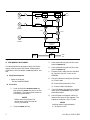
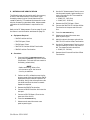
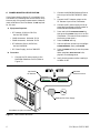
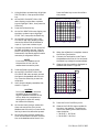
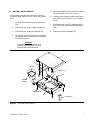
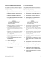
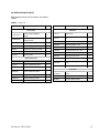
1
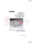
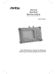
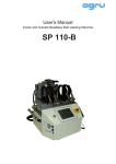
MAINTENANCE MANUAL
Site Master™ S820A
st
t
Te or
P
ry
e g
tt in
C
a rg
D ) B a
V A Ch
l
5 m
a
1
rn
2 C
e V
1 45
xt 2
(
E 1
l
a e
ri c
e fa
S er
t
In
Antenna and Coax/Waveguide Analyzer
F
R et
D
82
0A
1
AU
SCTO
AL
E
2
ST
CAART
L
3
CA
L
5
ES
C
CL AP
EA E
R
4
SA
SEVE
TU
P
RE
SE CAL
TU L
P
6
LIM
IT
7
MA
RK
ER
8
SA
DISVE
PL
AY
9
ON
OF
F
RE
DISCA
PLLL
AY
0
PR
IN
EN
TE
R
RU
HO N
LD
T
Figure 1.
Site Master S820A
1. INTRODUCTION
3. PERFORMANCE VERIFICATION
This manual provides maintenance instructions for
the Site Master S820A Antenna and Coax/ Waveguide Analyzer. It describes the product and provides
performance verification procedures, parts replacement procedures, and a replaceable parts list.
Paragraphs 4 through 7 contain tests that can be
used to verify the performance of the Site Master
model S820A having any version of firmware.
2. DESCRIPTION
The Site Master (Figure 1) is a hand held SWR/RL
(standing wave ratio/return loss) and Distance-ToFault measurement instrument. It combines a synthesized source, VSWR Bridge, and receiver on a
single printed circuit board (PCB). An optional
power monitor is also available. A block diagram is
shown in Figure 2.
490 JARVIS DRIVE ¨ MORGAN HILL, CA 95037-2809
3.1. Initial Setup for Testing
1.
Press and hold the ESCAPE/CLEAR key,
then press the ON/OFF key to turn on the
Site Master. (This sets the instrument to
the factory preset state.)
2.
Release the ESCAPE/CLEAR key and use
the Up/Down Arrow key to adjust the
contrast to give a readable display.
P/N: 10580-00031
REVISION D
PRINTED: FEBRUARY 2003
COPYRIGHT 1999-2003 ANRITSU CO.
Coupler
Multiplier
RF
Source
Coupler
Test
Port
Wave
Module
Multiplier
Local
Oscillator
Incident
Reflected
Local
Oscillator
Synchronous
Detector
A/D Converter
Display
Figure 2.
CPU
Serial
Port
Site Master Block Diagram
4. FREQUENCY ACCURACY
The following test can be used to verify the CW frequency accuracy of the Site Master. Measurement
calibration of the Site Master is not required for this
test.
3.
Press the F1 soft key, set to 9 GHz, then
press the ENTER key.
4.
Press the F2 soft key, set to 9 GHz, then
press the ENTER key.
5.
Connect the RF cable from the Site Master Test Port to the RF Input on the
MS2602A.
6.
Set up the Spectrum Analyzer as follows:
a. Equipment Required:
· Spectrum Analyzer
Anritsu Model MS2602A
(a) Press Preset.
(b) Press Center and enter 1 GHz.
b. Procedure:
(c) Press the Max Hold button.
1.
Press and hold the ESCAPE/CLEAR key,
then press the ON/OFF key to turn on the
Site Master. (This sets the instrument to
the factory preset state.)
NOTE
Before continuing, allow a five
minute warm up for the internal
circuitry to stabilize.
2.
2
Press the FREQ soft key.
7.
If the Site Master has gone into the hold
mode, press the RUN/HOLD key to make
the measurement.
8.
Use the Spectrum Analyzer marker to
measure the center of the response. The
frequency should be 1 GHz ±75 kHz.
NOTE
Nominal power is approximately
0 - 10 dBm at 1 GHz.
Site Master S820A MM
5. RETURN LOSS VERIFICATION
The following test can be used to verify the accuracy
of return loss measurements. Verification is performed by measuring the Source Match and Corrected Directivity. This method eliminates the uncertainties of measuring standard offset. Measurement
calibration of the Site Master is required for this
test.
Refer to the RF Measurement Chart on page 12, and
the Return Loss Verification worksheet on page 13.
a. Equipment Required:
· 19K50 Precision Airline
8.
Use the RF Measurement Chart to correlate the peak-to-peak ripple reading to a
return loss value in dB. The measured
value should be:
£ –18 dB (3.3 - 10.5 GHz)
£ –14 dB (10.5 - 20 GHz).
9.
Remove the 22KF50 Open / Short.
10.
Connect the 29KF50-15 Precision Offset
Termination to the open end of the airline.
11.
Press the AUTOSCALE key.
12.
Measure and record the worst case
peak-to-peak ripple.
13.
Add this value to the mean value of the
29KF50-15 Precision Offset Termination.
14.
Use the RF Measurement Chart to correlate the reading to a return loss value in
dB. The measured value should be:
£ –29 dB (3.3 - 20 GHz).
15.
Remove the airline and Precision Offset
Termination.
· 22KF50 Open / Short
· 22K50 Open / Short
· 29KF50-15 Precision Offset Termination
· 28K50 Precision Termination
b. Procedure:
1.
Press and hold the ESCAPE/CLEAR key,
then press the ON/OFF key to turn on the
Site Master. (This sets the instrument to
the factory preset state.)
NOTE
Before continuing, allow a five
minute warm up for the internal
circuitry to stabilize.
2.
Perform an OSL calibration over the frequency range of the unit using the 22K50
Open/Short and the 28K50 Precision Termination. Verify that noise spikes are below 44 dB and that the trace is smooth.
Repeat as required.
3.
Remove the 28K50 Termination.
4.
Connect a 19K50 Precision Airline to the
test port.
5.
Connect a 22KF50 Open / Short to the
open end of the airline.
6.
Press the AUTOSCALE key.
7.
Measure and record the worst case
peak-to-peak ripple.
Site Master S820A MM
3
2.
Connect the MA2418A Reference Source
to the input of the 560-7N50B RF detector.
3.
Connect the RF Detector output to the
RF Detector input of the Site Master.
4.
Connect the DC power supply to the appropriate line voltage to supply power to
the MA2418A Reference Source.
5.
Press and hold the ESCAPE/CLEAR key,
then press the ON/OFF key to turn on the
Site Master. (This sets the instrument to
the factory preset state.)
· 30 dB Attenuator, Weinshel 1R-30
6.
Press the MODE soft key.
· RF Reference Source, 0.050 GHz,
Anritsu MA2418A
7.
Use the Up/Down Arrow key to highlight
POWER MONITOR, then press ENTER.
· DC Power Supply, Anritsu 2000-933
8.
Press the ZERO soft key to zero the power
monitor.
When complete, ZERO ADJ:ON is displayed in the message area.
9.
Verify that the power monitor reading is
0.0 dBm ±1 dB.
6. POWER MONITOR VERIFICATION
If the Power Monitor (Option 5) is installed in the
Site Master, the following test can be used to verify
the accuracy of the power measurements. Measurement calibration of the Site Master is not required
for this test.
a. Equipment Required:
· RF Detector, 10 MHz to 20 GHz,
Anritsu 560-7N50B
· 10 dB Attenuator, Weinshel 1R-10
b. Procedure
1.
Connect the DC power supply to the
MA2418A Reference Source. (Refer to
Figure 3.)
Attenuators
MA2418A
Reference Source
ry
e g
tt in
C
a rg
D ) B a
V A Ch
l
5 m
a
rn
2 C
e V
1 45
xt 2
(
E 1
st
t
Te or
P
-1
l
a e
ri c
e fa
S er
t
In
MA2418A Reference Source
50 MHz, 50 W
0dBm
15-24V DC
20 mA
560-7N50B
RF Detector
1
AU
SCTO
AL
E
2
STA
CA RT
L
3
CA
L
ES
C
CL AP
EA E
R
4
SA
SEVE
TU
P
5
F
R et
D
82
0A
RE
SE CAL
TU L
P
6
LIM
IT
7
RK
ER
8
SA
DISVE
PL
AY
9
ON
OF
F
2000-933 DC Power Supply
MA
RE
DISCA
PLLL
AY
0
PR
IN
EN
TE
R
RU
HO N
LD
T
Site Master w/ Option 5 Installed
Figure 3.
4
Power Monitor Verification
Site Master S820A MM
10.
11.
12.
Connect the output of the MA2418A Reference Source to the two attenuators so
as to add 40 dB of attenuation (Figure 3).
b. Procedure
Connect the MA2418A Reference Source
and the attenuators to the input of the
560-7N50B RF detector.
Verify that the power monitor reading is
now –40.0 dBm ±2 dB.
1.
Connect the test equipment as shown in
Figure 3.
2.
Press the Power key on the 541XXA to
On.
3.
Press the System Menu key.
4.
Using the Menu up-down keys: Highlight
RESET, then press the Select key.
5.
At the RESET MENU display, use the
Menu up-down keys to highlight
RESET TO FACTORY DEFAULTS, then
press the Select key.
6.
Set the signal source for the frequency
range as follows:
7. TERMINATION VERIFICATION
This test can be used to verify the accuracy of terminations used with the Site Master. The test uses the
precision return loss mode of the 541XXA Scalar
Measurement System. Measurements of terminations using this mode provide results that are traceable to the NIST (National Institute of Standards
and Technology) standards for the precision airline.
(a) Press the Frequency key.
(b) Using the Data Entry Keypad or
Data Entry Knob, set the START frequency to 0.01 GHz. Press the Enter
key.
a. Equipment Required:
· Scalar Measurement System,
Anritsu 54161A/69A
(c) Using the Data Entry Keypad or
Data Entry Knob, set the STOP frequency to 20.0 GHz. Press the Enter
key.
· Offset SWR Autotester,
Anritsu 560-98KF50-15
· Precision Airline, Anritsu 19KF50
· Open/Short, Anritsu 22K50
7.
Press the Channel 2 Display On/Off key
to Off.
8.
Press the Channel 1 Menu key.
· 50 Ohm Termination, Anritsu 28K50
· Source Adapter, Anritsu K220B
Open/Short
50 Ohm
Termination
Termination
under Test
541XXA Scalar Measurement System
Beadless
End
Precision
Air Line
Connect Dashed Line Connections
When Directed By Procedure
A
B
Source
Adapter
Figure 4.
Offset SWR
Autotester
541XXA Precision Return Loss Test Setup
Site Master S820A MM
5
9.
10.
Using the Menu up-down keys: Highlight
PRECISION RL, then press the Select
key.
At the PRECISION RETURN LOSS
menu display, use the Menu up-down
keys to highlight FINAL, then press the
Select key.
11.
Press the Calibration key.
12.
At the CALIBRATION menu display, use
the Menu up-down keys to highlight
START CAL, then press the Select key.
13.
At the PRECISION RETURN LOSS
CALIBRATION menu display prompt,
connect the Offset SWR Autotester to
Input A, if you have not done so yet.
14.
Connect the precision air line to the Offset SWR Autotester test port. Position
the air line pointing vertically upward.
Downward or horizontal positions make
connector pin alignment difficult.
NOTE
Ensure that the beadless end of
the precision airline is at the
measurement connection point.
15.
Press the Select key when ready.
16.
At the PRECISION RETURN LOSS
CALIBRATION menu prompt, connect
the Open to the beadless end of the airline. Press the Select key to start the
calibration.
17.
1: PRECSN RL (A)
2: OFF
18.
At the next menu prompt, remove the
Open and connect the Short to the
beadless end of the airline. Press the Select key to start the calibration process.
19.
At the next menu prompt, remove the
Short and connect the 50 Ohm Termination to the beadless end of the air line.
10.0 dB/DIV OFFSET
+0.0dB
54147A
PRECISION
RETURN LOSS
CALIBRATION
1
CONNECT OPEN
TO AIRLINE
PRESS SELECT
WHEN READY
START: 0.0100 GHz
STOP: 20.0000 GHz
2 GHz/DIV
401 pts
Figure 5.
LEVEL +7.0 dBm
Example of a Good Connection
20.
When the calibration is complete, remove
the 50 Ohm Termination.
21.
Connect the Termination under Test to
the beadless end of the air line and press
the Select key to begin the measurement.
22.
Observe that the waveform displayed resembles that shown in Figure 6.
1: PRECSN RL (A)
2: OFF
10.0 dB/DIV OFFSET
+0.0dB
54147A
CURSOR
1: -46.02 dB
10.0050 GHz
Verify that the display resembles that
shown in Figure 5.
CAUTION
During both calibration and measurement, be sure to properly
align the beadless connector of the
airline. When the connectors are
mis-aligned, a spike will usually
be visible on the display.
6
Press the Select key to start the calibration process.
1
PRESS SELECT
FOR
CURSOR MENU
START: 0.0100 GHz
STOP: 20.0000 GHz
2 GHz/DIV
401 pts
Figure 6.
LEVEL +7.0 dBm
Direct Readout of the Precision Return Loss
23.
Press the Cursor On/Off key to On.
24.
Observe the CURSOR menu readout for
the return loss reading. The minimum
return loss reading for the 28K50 terminator should be:
£ –34 dB (3.3 - 18.5 GHz)
£ –29 dB (18.5 - 20 GHz).
Site Master S820A MM
8. BATTERY PACK REMOVAL
5.
Remove the bottom half (5) and fold it over to
lay upside down on the work surface.
This procedure provides instructions for removing
the battery pack. Refer to Figure 7 during this procedure.
6.
Disconnect the red/black cable of the battery
pack from J6 (6) of the Main RF PCB assembly (3).
7.
Remove the four screws (7) holding the battery bracket (8) in place and lift the bracket
clear.
8.
Remove the battery assembly (9).
1.
Place the Site Master face up on a work surface.
2.
Remove the four corner rubber bumpers (1).
3.
Remove the four screws (PN 900-811) (2).
4.
While holding the two halves of the Site Master together, turn it over and set it face down
on the work surface.
CAUTION
In the next step, the Main RF PCB
assembly (3) and test port panel (4)
must stay with the front panel.
5
9
Detail A
7 (4 Places)
6
8
10
N2
Raised
Wedge
3
74
Ext
er
Pownal
er
S
Inteerial
rfa
ce
Bat
Cha tery
rgin
g
Te
Po st
rts
.5-1
(8505V
D
mA C
)
12
2 (4 Places)
RF
De
t
4
1 (4 Places)
Figure 7.
Site Master Battery Removal
Site Master S820A MM
7
9. BATTERY PACK REPLACEMENT
10. BATTERY DISPOSAL
This procedure provides instructions for replacing
the battery pack. Refer to Figure 7 during the procedure.
The battery used in the Site Master is a rechargeable nickel-cadmium (NiCd) battery and is covered
by the Battery Directive (91/157/EEC). As such, the
battery is marked as follows to indicate controlled
disposal.
8
1.
Install the new battery assembly (9).
2.
Replace the battery bracket (8) and insert
the four screws (7) to hold the battery
bracket in place.
This marking indicates that
the battery is a recyclable
product.
3.
Reconnect the red/black cable of the battery
pack battery to J6 (6) on the main RF PCB
assembly (3).
4.
Set the bottom half in place.
This marking indicates that
the battery requires separate
collection and shows the
chemical system (Nickel/
Cadmium).
5.
While holding the two halves together, turn
the Site Master over and lay it face up on the
work surface.
6.
Reinstall the four screws (2).
7.
Install the rubber bumpers (1) on all four
corners of the instrument.
Component
% of Cell
Weight
Nickel
19 to 26%
Cadmium
17 to 22%
This marking indicates the
heavy-metal component
concentration as a percentage
of battery cell weight.
Spent nickel-cadmium batteries are valuable resources. Because they are reusable, do not throw
them away. Arrange for proper return for recycling
in your locality. If you do not have access to proper
disposal methods, return the battery pack to your
Anritsu service center. Service centers will dispose of
the unit at no charge. Anritsu Service Centers are
listed on page 14 of this manual.
Site Master S820A MM
11. KEY PAD MEMBRANE REPLACEMENT
12. LCD REPLACEMENT
This procedure provides instructions for replacing
the key pad membrane. Refer to Figure 7 (page 7)
during this procedure.
This procedure provides instructions for replacing
the Liquid Crystal Display (LCD). Refer to Figure 7
(page 7) during this procedure.
1.
Place the Site Master face up on a work surface.
1.
Place the Site Master face up on a work surface.
2.
Remove the four corner rubber bumpers (1).
2.
Remove the four corner rubber bumpers (1).
3.
Remove the four screws (PN 900-811) (2).
3.
Remove the four screws (PN 900-811) (2).
4.
While holding the two halves of the Site Master together, turn it over and set it face down
on the work surface.
4.
While holding the two halves of the Site
Master together, turn it over and set it face
down on the work surface.
CAUTION
In the next step, the PCB Assy (3)
and test port panel (4) must stay
with the front panel.
CAUTION
In the next step, the PCB Assy (3)
and test port panel (4) must stay
with the front panel.
5.
Remove the bottom half (5) and fold it over to
lay upside down on the work surface.
5.
Remove the bottom half (5) and fold it over to
lay upside down on the work surface.
6.
Disconnect the red/black cable of the battery
pack from the main PCB assembly connector
J6 (6).
6.
Disconnect the red/black cable of the battery
pack from the main PCB assembly connector
J6 (6).
7.
Remove the screw (10) located on the bottom
side of the main PCB assembly next to the
RF Bridge assembly .
7.
Remove the screw (10) located on the bottom
side of the main PCB assembly next to the
RF Bridge assembly .
8.
Pull the PCB assemblies clear from the top
half of the case.
8.
Pull the PCB assemblies clear from the top
half of the case.
9.
Lift the keypad membrane clear from the
keypad assembly.
9.
Remove the grey/brown cable of the LCD assembly from the main PCB assembly connector J8.
10.
Install a new membrane.
NOTE
Carefully use pliers to pull the rubber tabs tight to ensure that the
membrane is flush with the PCB.
11.
Reverse the above procedure to re-assemble
the Site Master.
Site Master S820A MM
10.
Remove the four screws from the LCD PCB
assembly.
11.
Carefully remove the 20-way ribbon cable
from the connector on the keypad PCB assembly.
12.
Install the new LCD PCB assembly. Use
thread locker on the LCD mounting screws.
13.
Reverse the above procedure to re-assemble
the Site Master.
9
13. MAIN PCB AND RF MODULE ASSEMBLY
REPLACEMENT
12.
This procedure provides instructions for replacing
the main PCB and RF module assembly. Refer to
Figure 7 (page 7) during this procedure.
NOTE
If the Power Monitor (Option 5) is installed, remove the two screws holding the Option 5 PCB assembly to
the test port panel and unsolder the
wires from pins 1 through 4 of the RF
Detector connector on the test port
panel.
NOTE
The test port panel is replaced as
part of the main PCB assembly.
1.
Place the Site Master face up on a work surface.
2.
Remove the four corner rubber bumpers (1).
3.
Remove the four screws (PN 900-811) (2).
4.
While holding the two halves of the Site
Master together, turn it over and set it face
down on the work surface.
Remove the four standoffs and the EMI
shield cloth.
13.
Carefully remove the serial number from the
test port panel.
14.
Install the serial number on the replacement
test port panel.
15.
Reverse the above procedure to re-assemble
the Site Master.
CAUTION
In the next step, the PCB Assy (3)
and test port panel (4) must stay
with the front panel.
5.
Remove the bottom half (5) and fold it over to
lay upside down on the work surface.
6.
Disconnect the red/black cable of the battery
pack from the main PCB assembly connector
J6 (6).
7.
Remove the screw (10) located on the bottom
side of the main PCB assembly next to the
RF Bridge assembly.
8.
Pull the PCB assemblies clear from the top
half of the case.
9.
Disconnect the grey/brown cable of the LCD
assembly from the main PCB assembly connector J8.
10.
Remove the four screws holding the LCD assembly, but do not disconnect the 20-way
connector from the keypad PCB assembly.
11.
Use pliers to gently squeeze the nine plastic
spacer heads to release them from the Keypad PCB assembly and carefully pull the
Keypad PCB with the LCD assembly from
the main PCB assembly.
10
Site Master S820A MM
14. REPLACEABLE PARTS
Replaceable parts for the Site Master are listed in
Table 1.
Table 1.
Parts List
Part Number
Description
Qty
Part Number
Description
Accessories
Hardware
10580-00030
User's Guide, Site Master
S820A
10580-00007
Battery Replacement and
Disposal Guide
1
2300-347
Software Tools, Site Master
1
40-115
Power Supply
1
806-62
Cable Assy, Cig Plug, Female
1
800-441
Serial Interface Cable Assy
1
D41955
Carrying Case
1
1
Replaceable Parts
B42893
EMI Shield
1
C41761
Liquid Crystal Display Assy
1
ND45417
Battery Pack Kit
1
ND52636
Main PCB Assy, S820A with
mwave module and cables
1
D41766-3
Keypad PCB Assy
1
D40864-2
Membrane Keypad, Main
1
C41767
Membrane, Soft Keys
1
Site Master S820A MM
Qty
790-171
Silicon Pad
1
761-10
Cap Vinyl, Black, round, 0.625
ID
1
790-52
Washer, #4, Shoulder, Nylon
1
900-257
Pan Head Screw, 0.312
4
790-445
Spacer PCB, 0.625, Self Mount
9
900-800
Pan Head Screw, #4, 0.312
1
900-811
Pan Head Screw, #4
4
900-326
Nut, Kep, 4-40, 0.312
4
900-697
Pan Head Screw, 4-40, 0.312
3
900-138
Screw, Pan, 2-56/patchlock,
0.18
4
B41753
Gasket, LCD
1
Case Parts
D40861-3
Case
1
C40863
Bumper
4
B48182
ID Label, Model S820A
1
11
Table 2.
RF Measurement Chart
Conversion tables for Return Loss, Reflection Coefficient, and SWR with tabular values for interaction of a small phaser x with a large phaser (unity reference) expressed in dB related to reference.
Relative to Unity Reference
(1 + X)
X
(1 - X)
(REF)
PHASOR
INTERACTION
12
SWR
Reflection
Coefficient
Return
Loss
(dB)
X
dB
Below
Reference
REF + X
dB
REF – X
dB
REF ± X
Peak to
Peak
Ripple
dB
17.3910
8.7242
5.8480
4.4194
3.5698
0.8913
0.7943
0.7079
0.6310
0.5623
1
2
3
4
5
1
2
3
4
5
5.5350
5.0780
4.6495
4.2489
3.8755
–19.2715
–13.7365
–10.6907
–8.6585
–7.1773
24.8065
18.8145
15.3402
12.9073
11.0528
3.0095
2.6146
2.3229
2.0999
1.9250
0.5012
0.4467
0.3981
0.3548
0.3162
6
7
8
9
10
6
7
8
9
10
3.5287
3.2075
2.9108
2.6376
2.3866
–6.0412
–5.1405
–4.4096
–3.8063
–3.3018
9.5699
8.3480
7.3204
6.4439
5.6884
1.7849
1.6709
1.5769
1.4935
1.4326
0.2818
0.2512
0.2239
0.1995
0.1778
11
12
13
14
15
11
12
13
14
15
2.1567
1.9465
1.7547
1.5802
1.4216
–2.8756
–2.5126
–2.2013
–1.9331
–1.7007
5.0322
4.4590
3.9561
3.5133
3.1224
1.3767
1.3290
1.2880
1.2528
1.2222
0.1585
0.1413
0.1259
0.1122
0.1000
16
17
18
19
20
16
17
18
19
20
1.2778
1.1476
1.0299
0.9237
0.8279
–1.4988
–1.3227
–1.1687
–1.0337
–0.9151
2.7766
2.4703
2.1986
1.9574
1.7430
1.1957
1.1726
1.1524
1.1347
1.1192
0.0891
0.0794
0.0708
0.0631
0.0562
21
22
23
24
25
21
22
23
24
25
0.7416
0.6639
0.5941
0.5314
0.4752
–0.8108
–0.7189
–0.6378
–0.5661
–0.5027
1.5524
1.3828
1.2319
1.0975
0.9779
1.1055
1.0935
1.0829
1.0736
1.0653
0.0501
0.0447
0.0398
0.0355
0.0316
26
27
28
29
30
26
27
28
29
30
0.4248
0.3796
0.3391
0.3028
0.2704
–0.4466
–0.3969
–0.3529
–0.3138
–0.2791
0.8714
0.7765
0.6919
0.6166
0.5495
1.0580
1.0515
1.0458
1.0407
1.0362
0.0282
0.0251
0.0224
0.0200
0.0178
31
32
33
34
35
31
32
33
34
35
0.2414
0.2155
0.1923
0.1716
0.1531
–0.2483
–0.2210
–0.1967
–0.1751
–0.1558
0.4897
0.4365
0.3890
0.3467
0.3090
1.0322
1.0287
1.0255
1.0227
1.0202
0.0158
0.0141
0.0126
0.0112
0.0100
36
37
38
39
40
36
37
38
39
40
0.1366
0.1218
0.1087
0.0969
0.0864
–0.1388
–0.1236
–0.1100
–0.0980
–0.0873
0.2753
0.2454
0.2187
0.1949
0.1737
1.0180
1.0160
1.0143
1.0127
1.0113
0.0089
0.0079
0.0071
0.0063
0.0056
41
42
43
44
45
41
42
43
44
45
0.0771
0.0687
0.0613
0.0546
0.0487
–0.0778
–0.0693
–0.0617
–0.0550
–0.0490
0.1548
0.1380
0.1230
0.1096
0.0977
1.0101
1.0090
1.0080
1.0071
1.0063
0.0050
0.0045
0.0040
0.0035
0.0032
46
47
48
49
50
46
47
48
49
50
0.0434
0.0387
0.0345
0.0308
0.0274
–0.0436
–0.0389
–0.0346
–0.0309
–0.0275
0.0871
0.0776
0.0692
0.0616
0.0549
1.0057
1.0050
1.0045
1.0040
1.0036
0.0028
0.0025
0.0022
0.0020
0.0018
51
52
53
54
55
51
52
53
54
55
0.0244
0.0218
0.0194
0.0173
0.0154
–0.0245
–0.0218
–0.0195
–0.0173
–0.0155
0.0490
0.0436
0.0389
0.0347
0.0309
1.0032
1.0028
1.0025
1.0022
1.0020
0.0016
0.0014
0.0013
0.0011
0.0010
56
57
58
59
60
56
57
58
59
60
0.0138
0.0123
0.0109
0.0097
0.0087
–0.0138
–0.0123
–0.0109
–0.0098
–0.0087
0.0275
0.0245
0.0219
0.0195
0.0174
Site Master S820A MM
RETURN LOSS VERIFICATION WORKSHEET
Source Match
Peak-to-Peak Ripple:
Return Loss Value:
Corrected Directivity
Peak-to-Peak Ripple:
Return Loss Value:
Sum of RLV and mean
(should be £ 32 dB):
Site Master S820A MM
13
Table 3.
Anritsu Service Centers
UNITED STATES
GERMANY
SOUTH AFRICA
ANRITSU COMPANY
685 Jarvis Drive
Morgan Hill, CA 95037-2809
Telephone: (408) 776-8300
FAX: 408-776-1744
ANRITSU GmbH
Grafenberger Allee 54-56
D-40237 Dusseldorf
Germany
Telephone: 0211-968550
FAX: 0211-9685555
ETESCSA
12 Surrey Square Office Park
330 Surrey Avenue
Ferndale, Randburt, 2194
South Africa
Telephone: 011-27-11-787-7200
Fax: 011-27-11-787-0446
ANRITSU COMPANY
10 NewMaple Ave., Suite 305
Pine Brook, NJ 07058
Telephone: 973-227-8999
FAX: 973-575-0092
ANRITSU COMPANY
1155 E. Collins Blvd
Richardson, TX 75081
Telephone: 1-800-ANRITSU
FAX: 972-671-1877
AUSTRALIA
ANRITSU PTY. LTD.
Unit 3, 170 Foster Road
Mt Waverley, VIC 3149
Australia
Telephone: 03-9558-8177
FAX: 03-9558-8255
BRAZIL
ANRITSU ELECTRONICA LTDA.
Praia de Botafogo 440. Sala 2401
CEP22250-040,Rio de Janeiro,RJ, Brasil
Telephone: 021-527-6922
FAX: 021-53-71-456
CANADA
ANRITSU INSTRUMENTS LTD.
700 Silver Seven Road, Suite 120
Kanata, Ontario K2V 1C3
Telephone: (613) 591-2003
FAX: (613) 591-1006
CHINA (SHANGHAI)
ANRITSU ELECTRONICS CO LTD
2F,Rm.B, 52 Section Factory Bldg.
NO 516 Fu Te Road (N)
Waigaoqiao Free Trade Zone
Pudong, Shanghai 200131
PR CHINA
Telephone: 86-21-58680226
FAX: 86-21-58680588
FRANCE
ANRITSU S.A
9 Avenue du Quebec
Zone de Courtaboeuf
91951 Les Ulis Cedex
Telephone: 016-09-21-550
FAX: 016-44-61-065
14
INDIA
MEERA AGENCIES (P) LTD
A-23 Hauz Khas
New Delhi, India 110 016
Telephone: 011-685-3959
FAX: 011-686-6720
ISRAEL
TECH-CENT, LTD
4 Raul Valenberg St.
Tel-Aviv, Israel 69719
Telephone: 972-36-478563
FAX: 972-36-478334
ITALY
ANRITSU Sp.A
Rome Office
Via E. Vittorini, 129
00144 Roma EUR
Telephone: (06) 50-2299-711
FAX: 06-50-22-4252
JAPAN
ANRITSU CUSTOMER SERVICE LTD.
1800 Onna Atsugi—shi
Kanagawa-Prf. 243 Japan
Telephone: 0462-96-6688
FAX: 0462-25-8379
SWEDEN
ANRITSU AB
Botvid Center
Fittja Backe 13A
145 84
Stockholm, Sweden
Telephone: (08) 534-707-00
FAX: (08)534-707-30
TAIWAN
ANRITSU COMPANY
7F, NO.316, Sec.1,
Nei Hu Road
Taipei, Taiwan, R.O.C.
Telephone: 886-2-8751-2126
FAX: 886-2-8751-1817
UNITED KINGDOM
ANRITSU LTD.
200 Capability Green
Luton, Bedfordshire
LU1 3LU, England
Telephone: 015-82-43-3200
FAX: 015-82-73-1303
KOREA
ANRITSU SERVICE CENTER
8F Hyunjuk-Bldg, 832-41
Yeoksam-Dong
Kangnam-Gu
Seoul, 135-080, Korea
Telephone: 82-2-553-6603
FAX: 82-2-553-6605
SINGAPORE
ANRITSU (SINGAPORE) PTE LTD
10, Hoe Chiang Road
#07-01/02
Keppel Towers
Singapore 089315
Telephone:65-282-2400
FAX:65-282-2533
Site Master S820A MM
NOTES