1
INSTALLATION GUIDE FOR
GREEN TEA™
5' x 36"
MODEL 3571
GREEN TEA™
5-1/2' x 36"
MODEL 3572
GREEN TEA™
6' x 36"
MODEL 3573
GREEN TEA™
5' x 42"
MODEL 3574
GREEN TEA™
6' x 42"
MODEL 3575
TOWN SQUARE®
5' x 42"
MODEL 2748
TOWN SQUARE®
6' x 42"
MODEL 2742
ELLISSE
OVAL
MODEL 2709
COMBINATION WHIRLPOOL AND
AIR BATH SYSTEMS WITH
CHROMATHERAPY LIGHTS
THANK YOU...
for selecting an American Standard bath. Your new bath is shipped to you after careful inspection. The Air
Massage System is completely assembled with air pump, motor, lights, and system piping. All you need to
finish the installation are your selected fittings and electrical connections for an Air Massage System.
To insure maximum performance and pleasure from this product, please follow the instructions and cautions.
FOR AFTER-SALES SERVICE CALL 1 (800) 442-1902 WEEKDAYS.
© AS America, Inc. 2009
All product names listed herein are trademarks of AS America, Inc. unless otherwise noted.
1
754323-100 Rev A
TABLE OF CONTENTS:
Cover................................................................................................Page 1
Table of Contents..............................................................................Page 2
Safety Instructions Notice.................................................................Page 3
Roughing-in Reference.....................................................................Page 4 - 12
Installation and Framing Instructions................................................Page 13 - 16
Supplied Drain Assembly and Installation Instructions.....................Page 16 - 20
Post Installation Instructions.............................................................Page 21
Remote Blower Location Option.......................................................Page 22
Warranty...........................................................................................Page 23
754323-100 Rev A
2
IMPORTANT SAFETY INSTRUCTIONS
READ AND FOLLOW ALL INSTRUCTIONS!
!
WARNING: Risk of personal injury. Do not permit children to use this bathtub without adult supervision.
!
WARNING: Risk of electric shock. Do not permit electrical appliances near any bathtub when bathtub contains water.
!
WARNING: Risk of hyperthermia and possible drowning. People using medications and/or having adverse medical
history should consult a physician before using this product.
!
WARNING: Risk of personal injury. Do not overfill bathtub before entering. Entering tub when filled more than 2/3 can
cause overflow and slippery conditions. Exercise caution when entering and exiting.
!
WARNING: No Food or Alcoholic Beverages. Use of your bathtub immediately after meals is not recommended. Avoid
alcohol consumption before or during bathing. Alcoholic beverages can cause drowsiness or hyperthermia resulting in loss of
consciousness or even drowning.
!
WARNING: Pregnancy. If you are or think you may be pregnant, consult your physician before using the bathtub.
Use this unit only for its intended use as described in this manual. Do not use any attachments not recommended by American
Standard.
The unit must be connected only to a supply circuit that is properly protected by a ground-fault circuit-interrupter (GFCI). Such a
GFCI should be provided by the installer and should be tested on a routine basis. To test the GFCI, push the test button. The
GFCI should interrupt power. Push the reset button. Power should be restored. If the GFCI fails to operate in this manner, the
GFCI is defective. If the GFCI interrupts power to the bathtub without the test button being pushed, a ground current is flowing,
indicating the possibility of an electric shock. Do not use this air bath. Disconnect the air bath and have the problem corrected by a
licensed electrician before using.
SAVE THESE INSTRUCTIONS
3
754323-100 Rev A
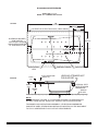
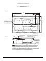
ROUGHING-IN REFERENCES
GREEN TEA™ 5' x 36"
MODEL 3571 COMBINATION SYSTEM
60
(1524mm)
TOP VIEW
OUTLINE OF CUTOUT 58.5 x 34.5 (1486 x 876mm)
14-3/4
(375mm)
11-1/2
(292mm)
36
(914mm)
ACCESS AIR BLOWER,
PUMP MOTOR,
WHIRLPOOL HEATER
AND LIGHTING SYSTEM
AT THIS END OF TUB
9
(229mm)
CL
CUTOUT IN FLOOR FOR DRAIN
CONTROL PANELS
8 WHIRLPOOL
JETS
END VIEW
51mm
(2")
CL TO OVERFLOW
102mm (4")
559mm
(22")
20 AIR JETS
LEVELING STRINGER NOT
FOR SUPPORT
INTEGRAL FEET
WITH ATTACHED
BASEBOARD
ROUGH
FLOOR
508mm
(20")
NOTE:
INSTALLER MUST PROVIDE 12 X 24 ACCESS OPENING FOR SERVICING AIR
BLOWER, PUMP MOTOR, WHIRLPOOL HEATER, AND LIGHTING SYSTEM.
THIS MODEL INCLUDES A DRAIN ASSEMBLY. OTHER DRAIN ASSEMBLIES
CANNOT BE USED. REVIEW DRAIN INSTALLATION DETAILS IN THE DOCUMENT
TO FULLY UNDERSTAND FLOOR CUTOUT REQUIREMENTS.
754323-100 Rev A
4
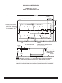
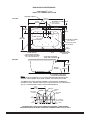
ROUGHING-IN REFERENCES
GREEN TEA™ 5-1/2' x 36"
MODEL 3572 COMBINATION SYSTEM
66
(1676mm)
TOP VIEW
OUTLINE OF CUTOUT 64.5 x 34.5 (1638 x 876mm)
14-3/4
(292mm)
11-1/2
(292mm)
ACCESS AIR BLOWER,
PUMP MOTOR,
WHIRLPOOL HEATER
AND LIGHTING SYSTEM
AT THIS END OF TUB
36
(914mm)
9
(229mm)
CL
CUTOUT IN FLOOR FOR DRAIN
8 WHIRLPOOL
JETS
51mm
(2")
END VIEW
CONTROL
PANELS
CL TO OVERFLOW
102mm (4")
559mm
(22")
22 AIR JETS
LEVELING STRINGER NOT
FOR SUPPORT
INTEGRAL FEET
WITH ATTACHED
BASEBOARD
ROUGH
FLOOR
508mm
(20")
NOTE:
INSTALLER MUST PROVIDE 12 X 24 ACCESS OPENING FOR SERVICING AIR
BLOWER, PUMP MOTOR, WHIRLPOOL HEATER, AND LIGHTING SYSTEM.
THIS MODEL INCLUDES A DRAIN ASSEMBLY. OTHER DRAIN ASSEMBLIES
CANNOT BE USED. REVIEW DRAIN INSTALLATION DETAILS IN THE DOCUMENT
TO FULLY UNDERSTAND FLOOR CUTOUT REQUIREMENTS.
5
754323-100 Rev A
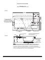
ROUGHING-IN REFERENCES
GREEN TEA™ 6' x 36"
MODEL 3573 COMBINATION SYSTEM
TOP VIEW
72
(1829mm)
14-3/4
(375mm)
11-1/2
(292mm)
OUTLINE OF CUTOUT 70.5 x 34.5 (1780 x 876mm)
ACCESS AIR BLOWER,
PUMP MOTOR,
WHIRLPOOL HEATER
AND LIGHTING SYSTEM
AT THIS END OF TUB
36
(914mm)
9
(229mm)
CL
CUTOUT IN FLOOR
FOR DRAIN
10 WHIRLPOOL
JETS
51mm
(2")
CL TO OVERFLOW
102mm (4")
CONTROL
PANELS
23 AIR JETS
LEVELING STRINGER NOT
FOR SUPPORT
END VIEW
559mm
(22")
INTEGRAL FEET
WITH ATTACHED
BASEBOARD
ROUGH
FLOOR
508mm
(20")
NOTE:
INSTALLER MUST PROVIDE 12 X 24 ACCESS OPENING FOR SERVICING AIR
BLOWER, PUMP MOTOR, WHIRLPOOL HEATER, AND LIGHTING SYSTEM.
THIS MODEL INCLUDES A DRAIN ASSEMBLY. OTHER DRAIN ASSEMBLIES
CANNOT BE USED. REVIEW DRAIN INSTALLATION DETAILS IN THE DOCUMENT
TO FULLY UNDERSTAND FLOOR CUTOUT REQUIREMENTS.
754323-100 Rev A
6
ROUGHING-IN REFERENCES
GREEN TEA™ 5' x 42"
MODEL 3574 COMBINATION SYSTEM
60
(1524mm)
TOP VIEW
OUTLINE OF CUTOUT 58.5 x 40.5 (1486 x 1029mm)
14-3/4
(375mm)
11-1/2
(292mm)
42
(1067mm)
ACCESS AIR BLOWER,
PUMP MOTOR,
WHIRLPOOL HEATER
AND LIGHTING SYSTEM
AT THIS END OF TUB
9
(229mm)
CL
CUTOUT IN FLOOR FOR DRAIN
CONTROL
PANELS
8 WHIRLPOOL
JETS
END VIEW
51mm
(2")
CL TO OVERFLOW
102mm (4")
559mm
(22")
23 AIR JETS
LEVELING STRINGER NOT
FOR SUPPORT
INTEGRAL FEET
WITH ATTACHED
BASEBOARD
ROUGH
FLOOR
508mm
(20")
NOTE:
INSTALLER MUST PROVIDE 12 X 24 ACCESS OPENING FOR SERVICING AIR
BLOWER, PUMP MOTOR, WHIRLPOOL HEATER, AND LIGHTING SYSTEM.
THIS MODEL INCLUDES A DRAIN ASSEMBLY. OTHER DRAIN ASSEMBLIES
CANNOT BE USED. REVIEW DRAIN INSTALLATION DETAILS IN THE DOCUMENT
TO FULLY UNDERSTAND FLOOR CUTOUT REQUIREMENTS.
7
754323-100 Rev A
ROUGHING-IN REFERENCES
GREEN TEA™ 6' x 42"
MODEL 3575 COMBINATION SYSTEM
TOP VIEW
72
(1829mm)
OUTLINE OF CUTOUT 70.5 x 40.5 (1780 x 1029mm)
14-3/4
(375mm)
11-1/2
(292mm)
42
(1067mm)
ACCESS AIR BLOWER,
PUMP MOTOR,
WHIRLPOOL HEATER
AND LIGHTING SYSTEM
AT THIS END OF TUB
9
(229mm)
CL
CUTOUT IN FLOOR FOR DRAIN
10 WHIRLPOOL
JETS
END VIEW
51mm
(2")
CL TO OVERFLOW
102mm (4")
559mm
(22")
CONTROL PANELS
27 AIR JETS
LEVELING STRINGER NOT
FOR SUPPORT
INTEGRAL FEET
WITH ATTACHED
BASEBOARD
ROUGH
FLOOR
508mm
(20")
NOTE:
INSTALLER MUST PROVIDE 12 X 24 ACCESS OPENING FOR SERVICING AIR
BLOWER, PUMP MOTOR, WHIRLPOOL HEATER, AND LIGHTING SYSTEM.
THIS MODEL INCLUDES A DRAIN ASSEMBLY. OTHER DRAIN ASSEMBLIES
CANNOT BE USED. REVIEW DRAIN INSTALLATION DETAILS IN THE DOCUMENT
TO FULLY UNDERSTAND FLOOR CUTOUT REQUIREMENTS.
754323-100 Rev A
8
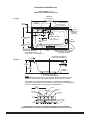
ROUGHING-IN REFERENCES
TOWN SQUARE® 5' x 42"
MODEL 2748 COMBINATION SYSTEM
CONTROL PANELS
59-1/2"
(1511mm)
TOP VIEW
INTEGRAL FITTING DECK
2-1/2" X 14"
(64 X 356mm)
29-3/4"
(755mm)
14-1/2"
(368mm)
3"
(76mm)
7-3/4" TYPICAL
(197mm)
41-5/8"
(1057mm)
FLOOR CUTOUT
9" X 18"
(229 X 458mm)
OUTLINE OF CUTOUT
58" X 40-1/8"
(1473 X 1019mm)
20 AIR JETS
3/4"
(19mm)
OUTLINE OF
SKID RESISTANT
SURFACE
6 WHIRLPOOL
JETS
ACCESS AIR BLOWER,
PUMP MOTOR,
WHIRLPOOL HEATER
AND LIGHTING SYSTEM
AT THIS END OF TUB
LEVELING STRINGER
(NOT FOR SUPPORT)
END VIEW
23"
(584mm)
21"
(533mm)
ROUGH
FLOOR
INTEGRAL FEET WITH
ATTACHED BASEBOARD
NOTE:
INSTALLER MUST PROVIDE 12 X 24 ACCESS OPENING FOR SERVICING AIR
BLOWER, PUMP MOTOR, WHIRLPOOL HEATER, AND LIGHTING SYSTEM.
THIS MODEL INCLUDES A DRAIN ASSEMBLY. OTHER DRAIN ASSEMBLIES
CANNOT BE USED. REVIEW DRAIN INSTALLATION DETAILS IN THE DOCUMENT
TO FULLY UNDERSTAND FLOOR CUTOUT REQUIREMENTS.
29-3/4
(755mm)
TO END OF TUB
C/L
DRAIN
FITTINGS
DECK
FOR SPOUT
& VALVES
FOR HAND
SPRAY
1-1/2
(38mm)
1-1/2
(38mm)
2-1/2
(64mm)
4-1/2
4-1/2
5
(114mm) (114mm) (127mm)
EDGE OF
FITTINGS
1-1/2
(38mm) DECK
HOLE DRILLING LOCATION FOR AMERICAN STANDARD "TOWN SQUARE"
DECK MOUNT BATH FILLER WITH PERSONAL SHOWER, MODEL #2555.901 ONLY
9
754323-100 Rev A
ROUGHING-IN REFERENCES
TOWN SQUARE® 6' x 42"
MODEL 2742 COMBINATION SYSTEM
CONTROL
PANELS
71-1/2"
(1816mm)
TOP VIEW
35-3/4"
(908mm)
13-1/4"
(337mm)
INTEGRAL
FITTING DECK
2-1/4" X 14"
(57 X 356mm)
3"
(76mm)
EDGE OF
FLOOR
CUTOUT
10-1/4”
(260mm)
26-3/4
(679mm)
8 WHIRLPOOL
JETS
7-3/4” TYPICAL
(197mm)
FLOOR CUTOUT
9" X 19"
(229 X 459mm)
AIR
BLOWER
3/4"
41-3/4" (19mm)
(1060mm)
OUTLINE OF SKID
RESISTANT SURFACE
ACCESS AIR BLOWER, PUMP
MOTOR, WHIRLPOOL HEATER
AND LIGHTING SYSTEM AT
THIS END OF TUB
20 AIR
JETS
OUTLINE OF CUTOUT
70" X 40-1/4" (1778 X 1022mm)
LEVELING STRINGER
(NOT FOR SUPPORT)
2"
(51mm)
END VIEW
22"
(559mm)
3-1/4"
(83mm)
20"
(508mm)
ROUGH
FLOOR
INTEGRAL FEET WITH
ATTACHED BASEBOARD
NOTE:
INSTALLER MUST PROVIDE 12 X 24 ACCESS OPENING FOR SERVICING AIR
BLOWER, PUMP MOTOR, WHIRLPOOL HEATER, AND LIGHTING SYSTEM.
THIS MODEL INCLUDES A DRAIN ASSEMBLY. OTHER DRAIN ASSEMBLIES
CANNOT BE USED. REVIEW DRAIN INSTALLATION DETAILS IN THE DOCUMENT
TO FULLY UNDERSTAND FLOOR CUTOUT REQUIREMENTS.
35-3/4
(908mm)
TO END OF TUB
C/L
DRAIN
FITTINGS
DECK
FOR SPOUT
& VALVES
FOR HAND
SPRAY
1-1/2
(38mm)
1-1/2
(38mm)
2-1/2
(64mm)
4-1/2
4-1/2
5
(114mm) (114mm) (127mm)
EDGE OF
FITTINGS
1-1/2
(38mm) DECK
HOLE DRILLING LOCATION FOR AMERICAN STANDARD "TOWN SQUARE"
DECK MOUNT BATH FILLER WITH PERSONAL SHOWER, MODEL #2555.901 ONLY
754323-100 Rev A
10
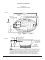
ROUGHING-IN REFERENCES
ELLISSE OVAL
MODEL 2709 COMBINATION SYSTEM
TOP VIEW
OUTLINE OF
CUTOUT
240 mm
(9-7/16")
978 mm
(38-1/2")
1759 mm
(69-1/4")
ACCESS AIR BLOWER, PUMP MOTOR,
WHIRLPOOL HEATER AND LIGHTING
SYSTEM AT THIS END OF TUB
7-3/4" TYPICAL
(197mm)
FLOOR CUTOUT
229 X 459mm
(9" X 19")
489mm
(19-1/4")
CONTROL
PANELS
16 AIR
JETS
END VIEW
38mm
(1-1/2")
6 WHIRLPOOL
JETS
C
L TO OVERFLOW
86mm (3-3/8")
INTEGRAL FEET
WITH ATTACHED
BASEBOARD
533mm
(21")
495mm
(19-1/2")
ROUGH
FLOOR
NOTE:
INSTALLER MUST PROVIDE 12 X 24 ACCESS OPENING FOR SERVICING AIR
BLOWER, PUMP MOTOR, WHIRLPOOL HEATER, AND LIGHTING SYSTEM.
THIS MODEL INCLUDES A DRAIN ASSEMBLY. OTHER DRAIN ASSEMBLIES
CANNOT BE USED. REVIEW DRAIN INSTALLATION DETAILS IN THE
DOCUMENT TO FULLY UNDERSTAND FLOOR CUTOUT REQUIREMENTS.
11
754323-100 Rev A
ROUGHING-IN REFERENCES
GREEN TEA™ 5-1/2' x 36"
MODEL 3572 COMBINATION SYSTEM
GREEN TEA™ 5' x 36"
MODEL 3571 COMBINATION SYSTEM
GENERAL SPECIFICATIONS FOR 3571
COMBINATION SYSTEM
INSTALLED SIZE
WEIGHT
WEIGHT w/WATER
GAL. TO OVERFLOW
MIN. OPERATING GAL.
BATHING WELL AT SUMP
BATHING WELL AT RIM
WATER DEPTH TO OVERFLOW
FLOOR LOADING
(PROJECTED AREA)
PTS.
CUBE (FT 3 )
GENERAL SPECIFICATIONS FOR 3572
COMBINATION SYSTEM
60 x 36 x 22 In. (1524 x 914 x 559mm)
117 Lbs. (53 Kg.)
550 Lbs. (250 Kg.)
52 Gal. (197 L.)
38 Gal. (144 L.)
19 x 43 In. (483mm x 1092mm)
48-1/2 x 27 In. (1232mm x 686mm)
14 In. (356mm)
37 Lbs./Sq. Ft. (179 Kgs/Sq. m.)
INSTALLED SIZE
WEIGHT
WEIGHT w/WATER
GAL. TO OVERFLOW
MIN. OPERATING GAL.
BATHING WELL AT SUMP
BATHING WELL AT RIM
WATER DEPTH TO OVERFLOW
FLOOR LOADING
(PROJECTED AREA)
PTS.
CUBE (FT 3 )
23.8
44.5
ELECTRICAL SPECIFICATIONS
•
GREEN TEA™ 5' x 42"
MODEL 3574 COMBINATION SYSTEM
GENERAL SPECIFICATIONS FOR 3574
COMBINATION SYSTEM
GENERAL SPECIFICATIONS FOR 3573
COMBINATION SYSTEM
INSTALLED SIZE
59-3/4 x 42 x 22 In. (1518 x 1060 x 559mm)
WEIGHT
141 Lbs. (64 Kg.)
682 Lbs. (310 Kg.)
WEIGHT w/WATER
65 Gal. (246 L.)
GAL. TO OVERFLOW
47 Gal. (178 L.)
MIN. OPERATING GAL.
24-1/2 x 42 In. (622mm x 1067mm)
BATHING WELL AT SUMP
48 x 33 In. (1219mm x 838mm)
BATHING WELL AT RIM
14 In. (356mm)
WATER DEPTH TO OVERFLOW
39 Lbs./Sq. Ft. (192 Kgs/Sq. m.)
FLOOR LOADING
(PROJECTED AREA)
27.8
PTS.
CUBE (FT 3 )
47.4
72 x 36 x 22 In. (1829 x 914 x 559mm)
143 Lbs. (65 Kg.)
693 Lbs. (314 Kg.)
66 Gal. (250 L.)
49 Gal. (185 L.)
19 x 55 In. (483mm x 1397mm)
60-1/2 x 27 In. (1537mm x 686mm)
14 In. (356mm)
38 Lbs./Sq. Ft. (188 Kgs/Sq. m.)
23.8
44.5
ELECTRICAL SPECIFICATIONS
•
TOWN SQUARE® 5' x 42"
MODEL 2748 COMBINATION SYSTEM
GREEN TEA™ 6' x 42"
MODEL 3575 COMBINATION SYSTEM
GENERAL SPECIFICATIONS FOR 3575
COMBINATION SYSTEM
GENERAL SPECIFICATIONS FOR 2748
COMBINATION SYSTEM
INSTALLED SIZE
59-1/2 x 41-5/8 x 23 In. (1511 x 1057 x 584mm)
WEIGHT
110 Lbs. (50 Kg.)
WEIGHT w/WATER
611 Lbs. (278 Kg.)
GAL. TO OVERFLOW
60 Gal. (227 L)
BATHING WELL AT SUMP
34 x 24 In. (864 x 610mm)
BATHING WELL AT RIM
52 x 31 In. (1321 x 1321mm)
WATER DEPTH TO OVERFLOW
12-1/2 In. (318mm)
FLOOR LOADING
29 Lbs./Sq.Ft. (144 Kgs./Sq.m)
(PROJECTED AREA)
PTS.
27.8
CUBE (FT 3 )
45.4
72 x 42 x 22 In. (1829 x 1067 x 559mm)
172 Lbs. (78 Kg.)
830 Lbs. (377 Kg.)
79 Gal. (299 L.)
58 Gal. (219 L.)
22-1/2 x 54 In. (572mm x 1372mm)
60 x 33 In. (1524mm x 838mm)
14 In. (356mm)
40 Lbs./Sq. Ft. (193 Kgs/Sq. m.)
ELECTRICAL SPECIFICATIONS
25.6
49.4
ELECTRICAL SPECIFICATIONS •
•
• REFER TO ELECTRICAL INSTALLATION DIAGRAM ON PAGE 14
• REFER TO ELECTRICAL INSTALLATION DIAGRAM ON PAGE 14
TOWN SQUARE® 6' x 42"
MODEL 2742 COMBINATION SYSTEM
ELLISSE OVAL
MODEL 2709 COMBINATION SYSTEM
GENERAL SPECIFICATIONS FOR 2742
COMBINATION SYSTEM
GENERAL SPECIFICATIONS FOR 2709
COMBINATION SYSTEM
INSTALLED SIZE
71-1/2 x 41-3/4 x 22 In. (1816 x 1060 x 559mm)
WEIGHT
174 Lbs. (79 Kg.)
WEIGHT w/WATER
830 Lbs. (313 Kg.)
GAL. TO OVERFLOW
69 Gal. (261 L)
BATHING WELL AT SUMP
41 x 21-1/2 In. (1041 x 546mm)
BATHING WELL AT RIM
62 x 31-1/2 In. (1574 x 800mm)
WATER DEPTH TO OVERFLOW
14-1/4 In. (362mm)
FLOOR LOADING
36 Lbs./Sq.Ft. (176 Kgs./Sq.m)
(PROJECTED AREA)
PTS.
27.8
CUBE (FT 3 )
55.7
ELECTRICAL SPECIFICATIONS
INSTALLED SIZE
69-1/4 x 38-1/2 x 19-3/4 In.(1759 x 978 x 502mm)
WEIGHT
119 Lbs. (54 Kg.)
WEIGHT w/WATER
652 Lbs. (296 Kg.)
GAL. TO OVERFLOW
64 Gal. (243 L)
BATHING WELL AT SUMP
45 x 23 In. (1143 x 584mm)
BATHING WELL AT RIM
63 x 32 In. (1600 x 813mm)
WATER DEPTH TO OVERFLOW
13 In. (330mm)
FLOOR LOADING
35 Lbs./Sq.Ft. (172 Kgs./Sq.m)
(PROJECTED AREA)
PTS.
25.6
CUBE (FT 3 )
49.4
•
ELECTRICAL SPECIFICATIONS
•
• REFER TO ELECTRICAL INSTALLATION DIAGRAM ON PAGE 14
• REFER TO ELECTRICAL INSTALLATION DIAGRAM ON PAGE 14
754323-100 Rev A
•
• REFER TO ELECTRICAL INSTALLATION DIAGRAM ON PAGE 14
• REFER TO ELECTRICAL INSTALLATION DIAGRAM ON PAGE 14
INSTALLED SIZE
WEIGHT
WEIGHT w/WATER
GAL. TO OVERFLOW
MIN. OPERATING GAL.
BATHING WELL AT SUMP
BATHING WELL AT RIM
WATER DEPTH TO OVERFLOW
FLOOR LOADING
(PROJECTED AREA)
PTS.
CUBE (FT 3 )
•
• REFER TO ELECTRICAL INSTALLATION DIAGRAM ON PAGE 14
GREEN TEA™ 6' x 36"
MODEL 3573 COMBINATION SYSTEM
ELECTRICAL SPECIFICATIONS
25.6
45.1
ELECTRICAL SPECIFICATIONS
• REFER TO ELECTRICAL INSTALLATION DIAGRAM ON PAGE 14
INSTALLED SIZE
WEIGHT
WEIGHT w/WATER
GAL. TO OVERFLOW
MIN. OPERATING GAL.
BATHING WELL AT SUMP
BATHING WELL AT RIM
WATER DEPTH TO OVERFLOW
FLOOR LOADING
(PROJECTED AREA)
PTS.
CUBE (FT 3 )
66 x 36 x 22 In. (1676 x 914 x 559mm)
128 Lbs. (58 Kg.)
619 Lbs. (281 Kg.)
59 Gal. (223 L.)
44 Gal. (167 L.)
19 x 49 In. (483mm x 1245mm)
54-1/2 x 27 In. (1384mm x 686mm)
14 In. (356mm)
38 Lbs./Sq. Ft. (188 Kgs/Sq. m.)
12
FIGURE 1
INSTALLATION AND FRAMING INSTRUCTIONS:
TYPICAL
INSTALLATION
The variety of installations possible for this combination system may require framing procedures
other than those shown. Locate studs as required. Ensure roughing-in dimensions are proper,
plumb and square. Provisions must be made in all installations for an access opening for servicing
the air blower and controls. It is strongly recommended that an additional opening be provided for
access to the drain components. The apron should not be used as the primary access opening.
1. Position the combination system into the installation opening and level the deck in both
directions, shimming the integral feet with attached baseboard as necessary. Refer to the
Combination Installation Table for nominal installation dimensions. Mark the final position of
the underside of the deck by tracing a line on to the studs (see Figure 1).
D
2. Remove the air massage system and attach a 1 x 4 stringer to the studs, with the top of the
stringer touching the traced line.
!
The rim of the bath must not support weight.
TILE
3. Install supplied cable drain components to the combination system according to the enclosed drain installation
instructions. Before replacing your bath for final installation, be certain that an opening has been provided in the
sub-floor for the drain. See the roughing-in drawing for suggested opening size (shadowed) and location
dimensions. The drain/overflow of the bath extends below the bottom of the bath. Note that this requires a cutout
in the floor.
WALLBOARD
SEALANT
TILE
BEAD
STRIP
BATH
ADHESIVE
4. Replace combination system and re-shim the integral support feet with attached baseboard, shimming the entire
length of the baseboard as needed. Secure the shims using construction adhesive, silicone or equivalent
materials.
!
LEVELING STRINGER
1 x 4 (not for support)
The rim of the bath must not support weight. Any finish material such as tile or wall board must be
self-supporting if it contacts the deck of the bath.
NOTE: Tile bead kit not included
and must be purchased separately.
DIM.
COMBINATION INSTALLATION TABLE
COMBINATION MODEL NUMBER
DESCRIPTION
2709 **
2748
2742
A Nominal tub length recess opening 59-3/4" 1518mm 71-3/4" 1823mm
3571
3572
3573
3574
60-1/4" 1530mm 66-1/4" 1683mm 72-1/4" 1835mm
3575
60" 1524mm 72-1/4" 1835mm
B Nominal tub apron support opening 39-3/4" 1511mm 39-3/4" 1511mm
35"
889mm
35"
889mm
35"
889mm 40-3/4" 1035mm
41" 1041mm
C Nominal tub width recess opening
36"
914mm
36"
914mm
36"
914mm 41-3/4" 1060mm
42" 1067mm
19"
483mm
19"
483mm
19"
483mm
19"
41-3/4" 1060mm 41-3/4" 1060mm
D Nominal tub height opening
21"
533mm
20"
E Nominal tub length cutout
58"
1473mm
70" 1778mm
F Nominal tub width cutout
508mm 19-1/2" 495mm
19"
483mm
483mm
67" 1702mm 58-1/2" 1486mm 64-1/2" 1638mm 70-1/2" 1791mm 58-1/4" 1480mm 70-1/2" 1791mm
40-1/8" 1019mm 40-1/4" 1022mm 36-1/2" 927mm 34-1/2" 876mm 34-1/2" 876mm 34-1/2" 876mm 40-1/4" 1022mm 40-1/2" 1029mm
** USE CUTOUT TEMPLATE PROVIDED FOR 2709 MODEL
NOTICE:
DO NOT BUILD THE SURROUNDING STRUCTURE BEFORE RECEIVING YOUR AIR BATH.
STRUCTURE MEASUREMENTS SHOULD BE VERIFIED AGAINST THE ACTUAL AIR BATH
RECEIVED TO ENSURE PROPER FIT.
TYPICAL PIER TYPE INSTALLATION
TYPICAL RECESS INSTALLATION
AS DESIRED
F
CUTOUT
E
CUTOUT
D
D
B
12
(305 mm)
C
12
(305 mm)
AS DESIRED
A
NOTE:
FRONT EDGE
OF BATH MUST
BE SUPPORTED
BY STUD WALL OR
AMERICAN STANDARD
APRON KIT
LEVELING
STRINGERS
MOUNTING
SURFACE
WATERPROOF
SEALANT
24
(610 mm)
ACCESS PANEL MUST BE LOCATED
ON THE SAME SIDE AS THE BLOWER.
ALLOW OPEN FRAMING ON
BLOWER END FOR SERVICE.
BATH
UNLESS AN ACCESS OPENING OF AT LEAST 12" X 24" (305 X 610mm)
IS PROVIDED, WARRANTY SERVICE WILL NOT BE PERFORMED.
24
(610 mm)
ACCESS PANEL MUST BE LOCATED
ON THE SAME SIDE AS THE MOTOR.
ALLOW OPEN FRAMING ON PUMP/MOTOR
END FOR SERVICE.
UNLESS AN ACCESS OPENING OF AT LEAST 12" X 24" (305 X 610mm)
IS PROVIDED, WARRANTY SERVICE WILL NOT BE PERFORMED.
13
754323-100 Rev A
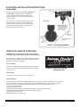
ELECTRICAL INSTALLATION INSTRUCTIONS
All wiring must be performed by a licensed electrician in accordance with the national electrical code and all other applicable codes.
! WARNING: When using electrical products, basic precautions should always be observed, including the following:
1. DANGER: RISK OF ELECTRIC SHOCK! Connect only to a circuit protected by a ground-fault circuit interrupter.
2. Grounding is required. The unit should be installed by a licensed electrician and grounded.
3. Permit access for servicing motor as noted.
4. All building materials and wiring should be routed away from the pump body and heater (if equipped).
“WHIRLPOOL WITH 2 LIGHTS”
CONFIGURATION
“AIR BATH”
CONFIGURATION
WHIRLPOOL TEE HEATER
W H IR L P OO L HE AT E R
1 2 0 V @ 1 3 A M AX
A IR B L O W E R
120V @ 10A MAX
2 LIGHTS
120V @ 1A
W HIRLP OOL P UM P
120V @ 15A MAX
P OW E R
D IS T R IB U T ION
BOX
GND.
20A GFCI OUTLET
20A GFCI OUTLET
BLACK
WHITE
WHITE
G ND.
120 VAC
BLACK
120 VAC
BLACK
WHITE
1 2 0 V AC
GND.
15A GFCI OUTLET
FIGURE 2: ELECTRICAL INSTALLATION DIAGRAM
This installation requires 3 separate 120VAC dedicated circuits with GFCI (Ground Fault Circuit Interrupter) protection as
shown in Figure 2. Two of the three GFCI outlets MUST be 20AMP service.
At initial start-up with the power ON, push the GFCI test button. The reset button should pop out. Push this button in to reset.
If the GFCI fails to operate in the manner, there is a ground fault or malfunction, indicating the possibility of electrical shock.
Turn off the power and do not use until the source of the problem has been identified and corrected.
754323-100 Rev A
14
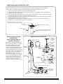
ELECTRICAL INSTALLATION INSTRUCTIONS
(continued)
(HEATER)
Ensure the heater and pump are properly GROUNDED
and BONDED as required. Attach the 8 AWG solid
copper conductor supplied with the heater from the
heater bonding lug to the motor frame bonding lug as
shown in Figure 3.
HEATER ON
E-Z INSTALL™
The conductor is secured to the lugs using set screws.
The motor frame shall have a second 8 AWG solid
copper conductor connected from the frame bonding
lug to the home’s electrical panel or approved local
bonding point as shown in Figure 3.
WHIRLPOOL
HEATER
(PUMP/MOTOR)
RUN 8 AWG SOLID COPPER
CONDUCTORS FROM
HEATER BONDING LUG TO
PUMP/MOTOR FRAME LUG
AND FROM PUMP/MOTOR
LUG TO APPROVED
GROUND AS SHOWN
FIRST COPPER
CONDUCTOR
SECOND
COPPER
CONDUCTOR
PUMP/MOTOR FRAME WITH
BONDING LUGS
TO GROUND
FIGURE 3: GROUNDING DIAGRAM
WHIRLPOOL HEATER OPERATION
WARNING: Prior to operation, review the Important Safety
Instructions listed at the beginning of this instruction manual.
Once the heater is installed and the whirlpool pump is operating,
the heater is totally automatic. The heater will help maintain the
temperature of the water in the bath.
WHIRLPOOL
E-Z INSTALL™ HEATER
HEATER “ON” LIGHT
Pressure Switch
FACTORY INSTALLED - NOT FOR RESALE
HEATER P/N: 753174-100
The heater is equipped with a preset pressure switch. The pump
must be running with water flowing in the whirlpool to allow the
heater to turn on.
Bonding Lug on
Heater Housing
FIGURE 4: WHIRLPOOL HEATER
INDICATOR LIGHT
Indicator Light
This light turns on whenever the heater is operating.
High-Limit Switch
The heater includes an exclusive "Intelligent High-Limit". This safety circuit will not "false trip" from hot tap water.
It will only turn the heater off if the thermostat fails. If the high-limit trips frequently, call a service technician.
To manually reset the circuit in the event that the “High-Limit” switch has been activated, simply
(1) Turn off the whirlpool pump.
(2) Drain water from the tub.
(3) Remove power from heater by unplugging at receptacle or turning off circuit breaker.
(4) The heater circuit will automatically reset in less than 15 minutes.
(5) Restore power to the heater.
(6) Whirlpool bath is now ready to use.
15
754323-100 Rev A
UNDER DECK MOUNTING INSTRUCTIONS
Please note that care must be taken to protect the surface of the tub during all aspects of the installation.
Do not drill or cut the bath deck with the tub directly beneath it as damage to the tub may result.
1.
2.
3.
4.
5.
6.
7.
8.
Install the tub per the installation instructions provided with the unit.
Prepare the bath deck support structure per the local codes. Note - the bath deck must be self supporting.
Cut bath deck to your specifications.
Place the bath deck in position and trace the opening on the tub with a soft pencil. Do not drill or cut the bath
deck with the tub directly beneath it as damage to the tub may result.
Remove the bath deck and apply a generous bead of waterproof sealant on the outer edge of the traced line.
Replace the bath deck and secure it into place.
Apply additional sealant along the tub and bath deck interface as necessary to ensure a watertight seal.
Remove excess sealant per the manufacturer's instructions.
Finished bath deck surface material must be
self-supporting and secured per local codes
Waterproof
Sealant
Bath deck support material
Bathtub
Tub support structure per installation
instructions provided with the tub
AIR BATH DRAIN ILLUSTRATION
DRAIN CONNECTION AND
SYSTEM TEST
(before installing bath into
framed out structure)
With supplied cable drain assembled to
bath, connect drain outlet to waste line in
accordance with the drain assembly
instructions. Tighten all drain joints
securely. Check the couplings and make
sure they are hand-tight. Clean the air
bath and fill with water to a point 2" below
the overflow. Recheck the couplings and
make certain that they are not leaking.
(Although the couplings are factory
tightened and inspected, some loosening
may have occurred during transit.) Make
sure the air bath is connected to the
electrical supply and turn the air bath on.
Check for leaks around all piping
connections while the air bath is running.
DRAIN STOPPER
WITH
ADJUSTABLE
BOLT
METAL STRAINER
BOLT
METAL
STRAINER
OVERFLOW
ASSEMBLY
CLOSE
FLAT RUBBER
GASKET
OPEN
DRAIN WASTE
FLANGE
PLASTIC DRAIN BASE
WEDGE
GASKET
VERTICAL
DRAIN PIPE
OVERFLOW
ESCUTCHEON
OVERFLOW
ASSEMBLY
SET
SCREW
DRAIN ACTUATOR SHAFT
OVERFLOW
RETAINER
OVERFLOW NUT WITH O-RING
AIR BATH NUT
WITH WASHER
AND GASKET
90˚ ELBOW
754323-100 Rev A
HORIZONTAL
DRAIN PIPE
16
PLASTIC
DRAIN BASE
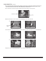
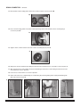
%3"*/$0//&$5*0/
3FNPWFBOEJEFOUJGZBMMESBJODPNQPOFOUTBTEFGJOFEJOBJSCBUIESBJOJMMVTUSBUJPO
'JOETDIFEVMF17$QJQFMFOHUI)03*;0/5"-%3"*/1*1&
$VUQJQFUPOPNJOBMMFOHUIBOENBSLBTiIPSJ[POUBMQJQFuESBJOUPFMCPXTFDUJPO
'JOEEJBNFUFS7&35*$"-'-&91*1&.BSLBTiWFSUJDBMQJQFu
ESBJOUPFMCPXTFDUJPO
*OTUBMMESBJOGSPNCFMPXVOJUUISPVHIPQFOJOHBTTIPXOJOQIPUP"
"
"QQMZPSQFBTJ[FEEBCTPGTJMJDPOFTFBMBOUUPCPUUPNXBTUFESBJOGMBOHFBOEQSFTTGMBUSVCCFSHBTLFUJOUPQMBDF
BTTIPXOJOQIPUPT#BOE$
#
$
"QQMZDPOUJOVPVTCFBEPGTJMJDPOFTFBMBOUUPGMBUSVCCFSHBTLFUBTTIPXOJOQIPUP%4FUBTJEFBOECFTVSFOPUUP
EJTUVSCTJMJDPOFCFBE
%
"QQMZDPOUJOVPVTCFBEPGTJMJDPOFTFBMBOUUPCBDLTJEFUPNFUBMTUSBJOFSBTTIPXOJOQIPUP&1SFTT
4USBJOFSSFUBJOJOHCPMUJOUPNFUBMTUSBJOFSBOEJOTFSUJOUPESBJOIPMFPGBDSZMJDCBUI
&
17
754323-100 Rev A
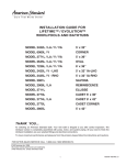
%3"*/$0//&$5*0/DPOUJOVFE
)BWFBTTJTUBOUUBLFESBJOBTTFNCMZGSPNTUFQBOEQMBDFPWFSCBDLTVSGBDFPGESBJOIPMFUPFOHBHFUIFNFUBMTUSBJOFSCPMU
4FDVSFQMBTUJDESBJOCBTFUPNFUBMTUSBJOFSJOESBJOPQFOJOHVTJOHOVUESJWFSTIBGU%0/0507&35*()5&/$BSFGVMMZ
SFNPWFFYDFTTTJMJDPOFGSPNBDSZMJDTVSGBDFBTEJSFDUFECZTJMJDPOFTFBMBOUEJSFDUJPOT
'SPNVOJUCBDLTJEFPWFSGMPXOVUTIPVMECFJOBMJHONFOUXJUIPWFSGMPXPQFOJOHBTTIPXOJOQIPUP'
'
0WFSGMPXOVU
0SJOH
4MJEFBJSCBUIGJUUJOHOVUXBTIFSBOEHBTLFUPOUPBJSCBUIGJUUJOHBTTIPXOJOQIPUPT(BOE)
(
)
"JSCBUI
GJUUJOH
"TTFNCMFBJSCBUIGJUUJOHUPQMBTUJDESBJOCBTFBTTIPXOJOQIPUPT*+,BOE-)BOEUJHIUFOOVUUPDSFBUFXBUFSUJHIUKPJOU
*
+
,
-
"QQMZ17$DFNFOUUP)PSJ[POUBM%SBJO1JQF17$BOEBTTFNCMFUPEFHSFFFMCPX
754323-100 Rev A
18
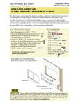
%3"*/$0//&$5*0/DPOUJOVFE
%JTBTTFNCMFPWFSGMPXXFEHFHBTLFUBOEDISPNFPWFSGMPXSFUBJOFSBTTIPXOJOQIPUP.
.
1MBDFPWFSGMPXXFEHFHBTLFUPOUPQMBTUJDPWFSGMPXQJQFGMBOHFXJUISPVOESBJTFESJCTVSGBDFDPOUBDUJOHGMBOHF
BTTIPXOJOQIPUP/
/
5JHIUFODISPNFPWFSGMPXSFUBJOFSPOUPESBJOPWFSGMPXBTTFNCMZQJQFQFSQIPUP0
0
"QQMZ17$DFNFOUUPCBSCFEFOEPGEFHSFFFMCPXBOEJOTFSUWFSUJDBMGMFYIPTFPWFSCBSCTBTTIPXOJOQIPUP1
"MJHOWFSUJDBMGMFYIPTFFOEPGQJQJOHXJUIUPQPGCBSCFEGJUUJOHMPDBUFEPOUIFPWFSGMPXGJUUJOHBOENBSLUIFGMFYIPTF
UPCFUSJNNFEBTTIPXOJOQIPUP2
$VUPGGFYDFTTWFSUJDBMGMFYIPTFBTTIPXOJOQIPUP3
"UUBDIWFSUJDBMGMFYIPTFUPCBSCFEGJUUJOHPOPWFSGMPXGJUUJOHCZQSFIFBUJOHUVCJOHBOEPSTPBQJOHCBSCFEGJUUJOHXJUI
EJTITPBQBTTIPXOJOQIPUP4
1
2
3
19
4
754323-100 Rev A
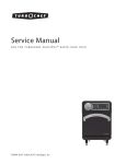
%3"*/$0//&$5*0/DPOUJOVFE
"MJHOGMBUPOESBJOBDUVBUPSTIBGUXJUIDPSSFTQPOEJOHGMBUJODISPNFNFUBMPWFSGMPXFTDVUDIFPOBOEUJHIUFOTFUTDSFXUPGJY
PWFSGMPXFTDVUDIFPOJOQMBDFQFSQIPUPT5BOE6
5
6
3PUBUFMFGUBOESJHIUMJHIUMZUPGFFMTUPQTJOESBJODBCMFDPOUSPM5IJTPQFOTBOEDMPTFTESBJO
1MBDFESBJOTUPQQFSJOUPESBJOXBTUFIPMFBTTIPXOJOQIPUP7
7
5IFESBJOTUPQQFSTIPVMEQSFWFOUXBUFSGSPNESBJOJOHPVUPGUVCXIFOUIFFTDVUDIFPOJTJOUIFGVMMZDPVOUFSDMPDLXJTF QPTJUJPOBTTIPXOJOQIPUP8"EKVTUUIFESBJOTUPQQFSCPMUUPPCUBJOUIFCFTUXBUFSTFBMJOUIFUVC
8
3PUBUF%SBJO&TDVUDIFPOUPDMPDLXJTFTUPQ5IJTTIPVMEPQFOESBJOCFUXFFOBOEUPBMMPXXBUFSUPFYJUCBUI
*GOPUBEKVTUNFUBMCPMUJOESBJOTUPQQFSUPBMMPXESBJOJOHGVODUJPOCVUOPUTPIJHIUIBUESBJOXJMMOPUTFBMXIFODMPTFEUP
IPMEXBUFSEVSJOHVTF4FFQIPUP9
9
754323-100 Rev A
20
1045*/45"--"5*0/$-&"/61
3FNPWFBMMDPOTUSVDUJPOEFCSJTGSPNCBUI5JMFHSPVUDBOCFSFNPWFEXJUIBXPPEFOQPQTJDMFTUJDLPSUPOHVFEFQSFTTPS
%POPUVTFXJSFCSVTIFTPSBOZPUIFSNFUBMJNQMFNFOUPOCBUITVSGBDF
1PTUJOTUBMMBUJPODMFBOVQHFOFSBMMZDBOCFDPNQMFUFEVTJOHXBSNXBUFSBOEMJRVJEEJTIXBTIJOHEFUFSHFOU
4UVCCPSOEJSUPSTUBJOTNBZCFSFNPWFEVTJOHHSBOVMBS4QJDBOE4QBO¡NJYFEXJUIXBUFS
1BJOUFShTOBQIUIBDBOCFVTFEUPSFNPWFFYDFTTBEIFTJWFTBOEPSXFUPJMCBTFQBJOU
"'5&3$"3&BOE$-&"/*/(
r5IFIJHIHMPTTTVSGBDFJTSFTJTUBOUUPJNQBDUBOEDIFNJDBMTBOEXJMMSFUBJOJUTMBTUJOHMVTUFSXJUIQSPQFSDBSFBOENBJOUFOBODF
r"MXBZTGJMMUIFUVCXJUIUFNQFSBUFXBUFS&YDFTTJWFMZIPUXBUFSNBZDBVTFTVSGBDFEBNBHF
r$MFBOBGUFSVTFXJUIBNJMEMJRVJEIPVTFIPMEEFUFSHFOUDMFBOFS%POPUVTF-FTUPJM-ZTPM%JTJOGFDUBOUTQSBZPSDPODFOUSBUF
PS-ZTPM#BTJO5VCBOE5JMF$MFBOFS8JOEFY.S$MFBO%PX%JTJOGFDUBOU#BUISPPN$MFBOFSPSDMFBOJOHQSPEVDUTJO BFSPTPMDBOT
)"34)$)&.*$"-44)06-%/&7&3#&64&%0/"$3:-*$463'"$&4
r%POPUVTFXJSFCSVTIFTLOJWFTPSTIBSQPCKFDUTUPSFNPWFTUBJOTDJHBSFUUFUBSEFQPTJUTPSPUIFSTVSGBDFCMFNJTIFT
r"CSBTJWFDMFBOFSTPSQPXEFSTNVTUOPUCFVTFETJODFUIFZXJMMEVMMUIFTVSGBDF*GUIFHMPTTZTVSGBDFMPPTFTJUTTIFFOEVMMFE
BSFBTDBOCFSFTUPSFECZSVCCJOHXJUIBXIJUFiBVUPNPUJWFUZQFuQPMJTIJOHDPNQPVOEBOEXBYJOHXJUIBiMJRVJEXBYu
r%POPUXBYBSFBTXIFSFZPVXBMLPSTUBOE
r%POPUBMMPXOBJMQPMJTISFNPWFSBDFUPOFESZDMFBOJOHGMVJEQBJOUSFNPWFSPSPUIFSTPMWFOUTUPDPNFJOUPDPOUBDUXJUI
UIFTVSGBDF
r$MFBOUIFTVSSPVOEJOHTVSGBDFJNNFEJBUFMZBGUFSVTJOHDBVTUJDESBJODMFBOFST
r#VSOJOHDJHBSFUUFTXJMMEBNBHFUIFTVSGBDF
r4IPVMEEBNBHFUPUIFGJYUVSFPDDVSSFQBJSTDBOCFNBEFRVJDLMZBOEFBTJMZ
:PVSEJTUSJCVUPSPSCVJMEFSDBOQSPWJEFEFUBJMT
r%POPUQFSNJUESBJODMFBOFSUPFOUFSUIFDJSDVMBUJPOTZTUFN
21
754323-100 Rev A
3&.05&#-08&3-0$"5*0/015*0/
*.1035"/5*UJTOPUOFDFTTBSZUIBUUIFCMPXFSNPUPSCFSFMPDBUFE5IJTPQUJPOJTQSPWJEFEGPSUIFDBTFUIBUBQBSUJDVMBS
JOTUBMMBUJPONBLFTUIJTFGGPSUQSBDUJDBM
/05&3FMPDBUJOHCMPXFSNPUPSGSPNGBDUPSZJOTUBMMFEMPDBUJPOTFFQIPUPXJMMSFRVJSFEJTBTTFNCMZPGBJSCMPXFSGSPNNPVOUJOH
CPBSE,FFQBMMIBSEXBSFGPSSFBUUBDINFOUBUOFXMPDBUJPO"EEJUJPOBMIBSEXBSFXJMMCFSFRVJSFEEFQFOEJOHVQPOGJOBMEFTJSFE
QPTJUJPOPGBJSCMPXFS'PMMPXBMMJOTUSVDUJPOTMJTUFECFMPX
5:1*$"-7*&8
/05&*OTUBMMJOHUIFCMPXFSJOBSFNPUFMPDBUJPOXJMMSFEVDFUIFTZTUFNFGGJDJFODZ
/05&3FMPDBUJOHBCMPXFSNPUPSTUJMMSFRVJSFTBTFSWJDFBDDFTTGPSUIFCMPXFS
/05&"MMNBUFSJBMTOFFEFEGPSUIFSFMPDBUJPONVTUCFTVQQMJFECZUIFJOTUBMMFS5IJTJODMVEFTPSEFSJOHBMPOHFSDPOUSPMQBOFMDBCMF
1/"
"TFQBSBUFDJSDVJUXIJDINVTUCFQSPUFDUFECZUIF(SPVOE'BVMU$JSDVJU*OUFSSVQUFS('$*
JTSFRVJSFEJOUIFSFNPUFMPDBUJPO
&MFDUSJDBMDPOOFDUJPOTTIPVMECFQFSGPSNFECZBMJDFOTFEFMFDUSJDJBO
$IPPTFBTQBDFBTDMPTFUPUIFCBUIBTQPTTJCMFTPUIFTZTUFNXPSLTBTFGGJDJFOUMZBTQPTTJCMF5IFTQBDFNVTUCFBUMFBTUDVCJD
GFFUBOEUIFCMPXFSNVTUCFNPVOUFEBUMFBTUJODIFTBCPWFUIFGMPPSBOEJODIFTNJOJNVNBXBZGSPNBOZXBMM5IFCMPXFSNVTU
/05CFJOTUBMMFEJOBOBUUJDBSFB
5IFCMPXFSNPUPSNVTUCFMPDBUFEXJUIJOGFFUPGSJHJEQJQJOHGSPNUIFCBUIBJSNBOJGPME5IJTMJNJUBUJPOJTGPSUIFUPUBMQJQFMFOHUI
BOEBQQMJFTUPBOZEJSFDUJPODIBOHFTBOEFMCPXT5IFSFDBOCFOPNPSFUIBOTJYDIBOHFTPGEJSFDUJPO5IFSFTIPVMECFBTGFX
EJSFDUJPODIBOHFTBTQPTTJCMFBOEUIFQJQJOHJOTUBMMBUJPONVTUNFFUBMMSFRVJSFNFOUTPGMPDBMQMVNCJOHBOECVJMEJOHDPEFT
%JTDPOOFDUUIFCMPXFSGSPNUIFGMFYJCMFIPTFBTTIPXOJOQIPUP%P/05SFNPWFUIFDIFDLWBMWFNBOJGPMEUIBUJTNPVOUFEUPUIF
VOEFSTJEFPGUIFBJSCBUI5IFNBOJGPME.645SFNBJONPVOUFEBCPWFUIFUVCPWFSGMPXMFWFMBTTIPXOJO
%P/05NPWFDIFDL
WBMWFNBOJGPME
5:1*$"-7*&8
6TFu17$SJHJEQJQJOHBOEDPVQMJOHTUPFYUFOEUIFCMPXFSNPUPSMPDBUJPOBTTIPXOJOQIPUPTBOE%FUBDIUIFGMFYJCMFIPTF
TFDUJPOGSPNUIFCMPXFSFOEBOEFYUFOEUIFBJSMJOFCZBEEJOHUIFBQQSPQSJBUFMFOHUIPG17$QJQJOH.PVOUUIFCMPXFSJOBIPSJ[POUBM
EJSFDUJPOVTJOHUIFNPVOUJOHTDSFXTQSPWJEFEXJUIUIFBJSCBUITZTUFN%P/05HMVFQJQJOHUPFJUIFSUIFNBOJGPMEPSCMPXFS5IFTF
DPVQMJOHT.645CFBUUBDIFEUPUIFQJQJOHXJUITDSFXTBTTIPXOJOQIPUPTBOE(MVFPOMZUIF17$QJQJOHBOEDPVQMJOHTOFFEFE
UPFYUFOEUIFBJSMJOF-FUUIFHMVFEDPVQMJOHTTFUPWFSOJHIUCFGPSFBUUBDIJOHUIFCMPXFSBOENBOJGPMEDPVQMJOHTXJUITDSFXT
$"65*0/*UJTJNQFSBUJWFUPMFUUIFHMVFEQJQJOHTFUPWFSOJHIUBTUIFSFNBZCFGVNFTGSPNUIFHMVFUIBUDPVMECFJHOJUFEJGOPU
BMMPXFEUPEJTTJQBUF
754323-100 Rev A
22
AS AMERICA, INC. LIMITED LIFETIME WARRANTY FOR LUXURY ACRYLIC WHIRLPOOLS
AS America, Inc. (“American Standard”) warrants to the original consumer purchaser that it will, at its option, repair or replace
this whirlpool or any of its parts that are found by American Standard, in its sole judgment, to be defective under normal
residential use and maintenance so long as it is owned by the original consumer purchaser.
This warranty shall only become effective upon receipt by American Standard of a Warranty Registration evidencing proof
of purchase.
This limited warranty does not apply to commercial installations. The warranty for commercial installations is three (3) years.
THIS WARRANTY SHALL BE VOID IF THE ACCESS PANEL TO THE WHIRLPOOL IS COVERED IN ANY MANNER
CONTRARY TO THE INSTALLATION INSTRUCTIONS. In no event will American Standard be liable for the cost of repair or
replacement of any installation materials including but not limited to tiles, marble etc.
This limited warranty DOES NOT COVER the following:
1. Defects or damages arising from shipping, installation, alterations, accidents, abuse, misuse, lack of proper maintenance and
cleaning as directed in the owner’s manual and use of other than genuine American Standard replacement parts, in all cases
whether caused by a plumbing contractor, service company, the owner or any other person.
2. Deterioration through normal wear and tear and the expense of normal maintenance.
3. Commercial application.
4. Options and accessories. American Standard’s limited warranty on these items is one year for parts only and excludes labor.
This one year limited warranty covers accessories manufactured by American Standard (e.g. aprons, drains, grab bars,
heaters, trim kits) against defects of material or workmanship. Warranty coverage begins on the date the accessory was
originally purchased by the owner.
5. Postage or shipping costs for returning products for repairs or replacement under this limited warranty and labor or other costs
incurred in connection with product removal or installation under this limited warranty.
6. ANY LIABILITY FOR CONSEQUENTIAL OR INCIDENTAL DAMAGES, ALL OF WHICH ARE HEREBY EXPRESSLY
DISCLAIMED, OR THE EXTENSION BEYOND THE DURATION OF THIS LIMITED WARRANTY OF ANY IMPLIED
WARRANTIES, INCLUDING THOSE OF MERCHANTABILITY OR FITNESS FOR AN INTENDED PURPOSE. (Some
jurisdictions do not allow limitations on how long an implied warranty lasts, or the exclusion or limitation of incidental or
consequential damages, so these limitations and exclusions may not apply to you.)
7. Responsibility for compliance with local code requirements. (Since local code requirements vary greatly distributors, retailers,
dealers, installation contractors and users of plumbing products should determine whether there are any code restrictions on
the installation or use of a specific product.)
This limited warranty gives you specific legal rights. You may have other statutory rights that vary from state to state or from
province to province, in which case this limited warranty does not affect such statutory rights.
For service under this warranty, you should contact the following:
In the United States:
American Standard Brands
P.O. Box 659
West Caldwell, NJ 07007
Attention: Whirlpool Customer Care Center
For residents of the United States, warranty
information may be obtained by calling the
following toll free number: (800) 442-1902
In Canada:
AS Canada ULC
2480 Stanfield Road
Missassauga, Ontario
Canada L4Y 1S2
Toll free: (800) 387-0369
www.americanstandard.ca
In Mexico:
Customer Service Manager
AS Maquila, S.A. de C.V.
Via Morelos #330
Col. Santa Clara
Ecatepec 55540 Edo. Mexico
www.americanstandard.com.mx
www.americanstandard-us.com
To register your product on-line, visit http://www.americanstandard-us.com/warranty
If you do not have access to a computer, please call us at 1-800-442-1902 and we’ll
register you on-line.
23
754323-100 Rev A