1
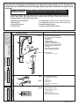
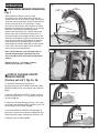
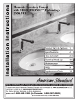
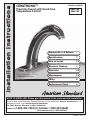
Installation Instructions
CERATRONIC™
PRODUCT NUMBERS
Proximity Faucet with Touch-Free
Temperature Control
Certified to comply with ASME A112.18.1M
© 2006 American Standard
M 9 6 8 8 5 7 R E V. 1. 2
6058.105
6058.102
Product No.'s & Options
1
Specifications
2
How to Install
2-3
Electrical Hook-up
4
Operation
5-6
Maintenance
6-8
FAQ,s
8
Replacement Parts
9
NOTE TO INSTALLER: Please give this manual to the customer after installation.
To learn more about American Standard Faucets visit our website at: www.us.amstd.com or U.S.
customer's e-mail us at: [email protected]
For Parts, Service, Warranty or other Assistance,
please call 1-800-442-1902 (In Canada: 1-800-387-0369)
(In Toronto Area only: 1-905-3061093)
M 9 6 8 8 5 7 R E V. 1. 2
Thank you for selecting American-Standard...the benchmark of fine quality for over 100 years. To
ensure that your installation proceeds smoothly--please read these instructions carefully before
you begin.
UNPACKING
All American Standard Faucets Are Water Tested At Our Factory.
Some Residual Water May Remain In The Faucet During Shipping.
1. Remove the fitting and loose items from the carton. The illustration below shows the fitting
and all loose items after they have been removed from the carton. Some items may be
packaged partially assembled to other items.
1.Ceratronic Spout Assembly
2. Mounting Kit
3. Electrical Enclosure
4. Supply Hoses
5. 4" Deck plate ( optional must be ordered separately)
6. 8" Deck plate ( optional must be ordered separately)
7. Optional Remote Control
8. Key for vandal resistant aerator
Part Number
6058.105
8
1
Description
Ceratronic Proximity Faucets
• Colored LED's signal temperature
change mode
• Cast spout
• Vandal resistant
• 0.5/gpm, 1.9L/min Spray
• Fully enclosed, water-resistant
• AC Plug-in Power supply included
• 3/8" SS compression flex hoses,
15" length
• Order deck plate and remote
control separately (optional)
B
a
s
e
6058.102
Same as above
• 2.2 gpm/8.3L/min. aerator
605P400
4" Deck plate, cast brass
• 1/4" fixation bolts at 4" centers;
Spin nuts
605P800
8" Deck plate
• Cast brass
• 1/4" fixation bolts at 8" centers;
Spin nuts
605XRCN
Optional Remote Control
2
d
u
3
c
Base Product
t
• Single Hole Sink
• Hot and Cold Inlets
P r o
How to order the Selectronic Product
1. Choose Power Supply
2. Choose Desired Spout
Ceratronic
Lavatory Faucets
4
Deck Plate
Deck Plate (optional)
• 1 and 3 Hole Sinks
• Hot and Cold Inletst
5
6
Remote Control
Remote Control
7
• Change functions or adjust
setup parameters
• Battery Powered
• Can be used to operate all
Selectronic™ fittings and fixtures
Val
Can
1
M 9 6 8 8 5 7 R E V. 1. 2
Roughing-in Dimensions
183mm
(7-3/16)
190mm
(7-7/16)
GENERAL DESCRIPTION:
Electronic faucet with proximity operation. Colored
LED's signal temperature change mode. Vandal
resistant solid brass construction single post mounting.
Operates on AC permanent power. Water pressure
range from 20 to 80 psi. In-line strainer for solenoid is
integral. Single inlet 3/8 compression, built-in checks,
and flexible stainless steel 15" reach inlet hose for
spout connection.
143mm
(5-5/8)
132mm
(5-3/16)
55mm D.
(2-3/16)
25mm MAX.
(1)
381mm
(15)
270mm MAX.
(10-5/8)
3/8"
COMP.
175mm MAX.
(6-7/8)
CODES AND STANDARDS:
These products meet or exceed the following coded
standards:
ANSI A117.1
ADA Compliant
ASME A112.18.1
CSA B 125
NSF 61/Section 9
114mm
(4-1/2)
3/8"
COMP.
81mm
(3-3/16)
125mm
(4-7/8)
1524mm
(60)
3/8" COMP.
508mm
(20)
TOOLS REQUIRED
1 Channel Locks
2 Adjustable Wrench
3 Plumbers' Putty or
Caulking
4 Phillips Screwdriver
1
5 Flat Blade Screwdriver
6 Electric Drill & 1/4" Drill Bit
7 Tape Measure
2
4
3
5
10'
6
7
INSTALLATION
Fig. 1
1 INSTALL SPOUT ASSEMBLY;
4
3
Fig. 1
CAUTION
Turn off hot and cold water
supplies before beginning
1. (Optional) Assemble DECK PLATE (1) and PUTTY
PLATE (2) to FAUCET BODY (3) with SCREW (4). Fig.
1.
2
1
2. Insert WIRES (5), FLEX HOSE (6) and SPOUT
SHANK (7) through center hole of mounting surface.
Fig. 1a.
Fig. 1b
Fig. 1a
3. Assemble "C" WASHER (8) and LOCKNUT (9)
onto threads of SPOUT SHANK (7) from underside of
mounting surface. Fig. 1b.
9
7
10
5
6
4. Align FAUCET (3) and tighten LOCKNUT (9). If using
DECK PLATE (1) hand tighten DECK PLATE SPIN
NUTS (10) to secure FAUCET (3) to mounting surface.
Fig. 1b.
7
8
2
M 9 6 8 8 5 7 R E V. 1. 2
2 MOUNT ENCLOSURE; Fig. 2
Fig. 2
1. Determine location of ENCLOSURE (1). It must be
located with-in the 14" (356mm) by 21" (533mm)
shaded area shown in Fig. 2 in order for electrical
connections from the spout assembly to be made.
NOTE: ENCLOSURE SUPPLY HOSE is 20". Distance
between wall supply and ENCLOSURE (1) must be
taken into consideration.
LAVATORY RIM OR
MOUNTING SURFACE
14"
(356mm)
SUPPLIES
ENCLOSURE
MOUNTING
HOLES
1
2-3/4"
(71mm)
2. Remove 4 screws from COVER (2) and pull off
COVER (2). Hold the ENCLOSURE (1) in desired
location and mark the four mounting hole locations as
shown. Fig. 2.
WASTE
1524mm
(60)
20"
(500mm)
21"
(mm)
3"
(76mm)
3-3/4"
(96mm)
MOUNTING HOLES
3. The ENCLOSURE (1) works best if secured to a wall
stud or cross brace within the wall, using the SCREWS
(3) supplied. If the ENCLOSURE (1) is to be installed on
a tile or plaster wall the ANCHORS (4) and SCREWS
(3) should be used.
3
1
2
4
1
4. For installations on drywall or tiled walls; use
ANCHORS (4) and SCREWS (3) for securing
ENCLOSURE (1) to finished wall. Drill four 1/4" dia.
holes a minimum of 1-3/4" deep. Insert the four
ANCHORS (4) flush with face of the finished wall.
Align the ENCLOSURE (1) and Install the MOUNTING
SCREWS (3). Tighten to secure ENCLOSURE (1) to
mounting surface.
Fig. 3
1
2
3 CONNECT SPOUT HOSE TO
ENCLOSURE; Fig. 3
1. Connect SUPPLY NUT (1) from spout assembly to
nipple on top of ENCLOSURE (2). Tighten with
adjustable wrench to make a water tight connection.
Fig. 3.
Fig. 4
4 CONNECT HOSES TO WALL
Fig. 4a
RED
DOT
SUPPLY; Fig. 4
1. Insert FIBER WASHERS (4) into SUPPLY NUTS (1)
on ENCLOSURE (2). Fig. 4.
BLUE
DOT
2
1
4
2. Connect SUPPLY NUT (1) on ENCLOSURE (2) to
FLEXIBLE SUPPLY HOSE (3). Tighten to make a
water tight connection. Use two wrenches if necessary.
Fig. 4a.
2
3
1
Fig. 4b
3. Connect FLEXIBLE SUPPLIES (3) corresponing to the
red dot on ENCLOSURE (2) to the hot water supply,
and the FLEXIBLE HOSE (3) corresponding to the blue
dot to cold water supply. Connection on FLEXIBLE
SUPPLIES (3) are 3/8" compression. Use adjustable
wrench to tighten connection. Do not over tighten.
FIG. 4b.
HOT
Note: FLEXIBLE SUPPLY (3) measures 20" from the
bottom of the ENCLOSURE (2) base. If additional
supply length is required, installer must purchase
parts separately.
Important: If FLEXIBLE SUPPLIES (3) are too long, loop
to avoid kinking.
3
3
COLD
3
2
HOT
COLD
M 9 6 8 8 5 7 R E V. 1. 2
Fig. 1
ELECTRICAL INSTALLATION
3
1 ELECTRICAL
1
2
1. Remove ENCLOSURE COVER (1). Fig. 1.
2. Remove CIRCUIT BOARD (2) from ENCLOSURE
(3). (May have to pull cord of power supply through).
Fig. 1.
3. Feed the WIRE CONNECTORS (4) through the top
of ENCLOSURE (3). Fig. 1b.
4. Remove SPLIT PLUG (5) from GROMMET (6).
Insert the gray SENSOR WIRE (7) and YELLOW and
GREEN CONNECTOR WIRES (8) into SPLIT PLUG
(5). Leave 4” of wire from end of SPLIT PLUG (5). Fig.
1c. Feed WIRES (7 & 8) through GROMMET (6). Push
SPLIT PLUG (5) into GROMMET (6) to seal. Fig. 1d.
Fig. 1c
Fig. 1b
6
3
5
7
8
5. Reinstall CIRCUIT BOARD (2) into ENCLOSURE (3)
with WIRES (7 & 8) under CIRCUIT BOARD (2). Insert
two WIRE CONNECTORS (9) into any of the three
CIRCUIT BOARD RECEPTORS (10). Fig. 1e.
4
6. Connect WIRE PLUGS (11) to SOLENIOD VALVE
(12). (Red to +, Blue to -). Fig. 1f.
3
Fig. 1d
Fig. 1e
2
7. Connect SENSOR WIRE CONNECTIONS (13) to
WIRE PLUGS (11). Red to +, Black to -). Fig. 1g.
7
9
5
6
8. Connect WHITE PLASTIC CONNECTOR (14) from
the faucet to the MOTOR CONNECTOR (15). Fig. 1h.
10
9. Replace ENCLOSURE COVER (1). Tighten cover
screws firmly. Fig. 1k.
8
Fig. 1f
Fig. 1g
13
11
11
12
Fig. 1h
Fig. 1k
15
1
14
4
M 9 6 8 8 5 7 R E V. 1. 2
OPERATION
Fig. 1
1 HAND WASH SENSOR OPERATION;
BLUE
SENSOR
RED
SENSOR
Fig. 1
When the Sensor detects a user, the water
immediately starts to flow. Water flow will stop Two
seconds after user is out of sensor range. The off delay
allows the user to comfortably move his hands without
the flow cycling on to off. As a precaution, a safety
timer will turn off the water, after the sensor has been
blocked for 59 seconds. The water will stay off until the
blockage is removed from the detection zone.
Output water temperature has a default setting. See
Section 3 for “How to Set Default Temperature.” To
change the output water temperature place one hand
within the On/Off Sensor range to activate faucet, then
place other hand within the Blue Sensor to decrease
water temperature, or the Red Sensor to increase
water temperature. Blue or Red LED will light up when
hand is within the sensor range. The Blue and Red
sensor ranges cannot be adjusted.
TION
DETEC E
ZON 50mm)
(50mm-2
2" -10"
ON/OFF SENSOR
Fig.
Fig. 22
Note: If On/Off Sensor is not activated within 15
seconds of temperature adjustment, then the
faucet will adjust back to the default temperature
settings.
1
Detection Zone: 2" - 10" (50mm - 250mm)
Default: Set at Factory 6" (150mm)
2 HOW TO CHANGE ON/OFF
SENSOR RANGE;
(Factory set at 6") Fig. 2a, 2b
1. Setting the Detection Zone (Distance):
Remove cover from ENCLOSURE. Disconnect GRAY
SENSOR WIRE (1) from circuit board, then reconnect.
Fig. 2.
Fig. 2a
1" - 2" (30mm - 50mm)
2. While the SENSOR CONTROL LED (2) is blinking
slowly, place your hand 1 - 2 in. (30-50mm) in front of
the sensor. Fig. 2a.
3. When the LED stops blinking and stays "ON", move
your hand to the desired position and hold in place until
the LED begins to blink again. Fig. 2b.
2
BLINKING LED
Fig. 2b
4. Once the SENSOR CONTROL LED (2) begins to
blink again, remove your hand from the detection zone.
When the flashing stops, the detection distance is set.
UP TO 10" (250mm)
5. Replace cover on ENCLOSURE.
2
5
BLINKING LED
M 9 6 8 8 5 7 R E V. 1. 2
3 HOW TO SET DEFAULT
Fig. 23
Fig.
Fig. 3a
ADJUST
COLD
TEMPERATURE Fig. 3
BLUE
SENSOR
Note: The factory setting of the Default Temperature is
at a position of even amounts of hot and cold water
flows. This setting can only be changed within the first
15 minutes of switching on the power.
ADJUST HOT
RED SENSOR
1. Remove the power to the faucet by unplugging the
Power Supply from the wall outlet. Wait 60 seconds, and
then plug the Power Supply Back into the wall outlet.
2 . Place hand in front of Blue (Cold) Sensor until the
Blue LED lights up. Fig. 3.
3. Within the next 5 seconds, start the faucet water flow
by placing hand within the On/Off Sensor range. Fig. 3.
Fig. 1
4. Adjust the output faucet temperature by using the
Red (Hot) Sensor to increase, or Blue (Cold) Sensor to
decrease. During this process always keep your hand
within The On/Off Sensor range in order to feel the
change water temperature. Fig. 3, Fig. 3a.
Fig. 1a
3
5. Once desired temperature has been set, remove
hands away from the range of sensors. Water flow will
stop and both Red and Blue sensors will light-up for 2
seconds indicating the default temperature has been set.
2
4
5
6. The Default Temperature has been set. This will
remain the default setting untill the setting is changed
again. If power is lost, this will remain the default
setting.
6
1
6
Fig. 1b
Note: The Default Setting is actually a mechanical
positioning of a mixing valve. Changes in the
supply temperatures will create changes to the
Default Temperature.
MAINTENANCE
7
1 HOW TO REMOVE MIXING
Fig. 1c
VALVE Fig. 1
1. Remove four screws and pull off ENCLOUSURE
COVER (1). Fig. 1.
INSTALL
2. Remove MOTOR GEAR COVER (2) by pulling off or
pry off with a flat-blade screw driver. Fig. 1a.
REMOVE
3. Remove SCREW (3) from the center of the LARGE
GEAR (4) and two SCREWS (5) from the MOTOR
HOUSING (6). Fig. 1a.
8
9
Fig. 1d
4. Pull of MOTOR HOUSING (6) with LARGE GEAR
(4) from the MIXING VALVE STEM (7). Fig. 1b.
5. Remove LOCKNUT (8) from the MIXING VALVE
HOUSING (9) using adjustable wrench. Fig. 1c.
10
6. Pull out MIXING VALVE (10). Use pliers if necessary.
Fig. 1d.
7. Reverse above steps for assembly.
6
M 9 6 8 8 5 7 R E V. 1. 2
2 HOW TO CLEAN FILTER; Fig. 2
CAUTION
Fig. 2
Before opening ENCLOSURE
disconnect AC power supply.
1. Remove ENCLOSURE COVER.
2. Close SUPPLY STOPS.
Note: Keep water flowing out of faucet while shutting off.
1
CLEAN
SCREENS
4. Unthread STRAINER (1) using a 7/16" socket.
1
5. Pull out the STRAINER (1) and clean with an old
toothbrush. Rinse thoroughly with water.
INSTALL
6. Install the STRAINER (1) back in its place and
tighten with a 7/16" socket.
Caution: do not over tighten strainer.
Note: It is recommended to clean strainer every 6
months.
REMOVE
7. Replace ENCLOSURE COVER. Tighten cover
screws firmly.
3 HOW TO CLEAN AND REMOVE
Fig. 3
Fig.5
THE AERATOR; Fig. 3
1. Remove AERATOR HOUSING (1) with KEY (2)
supplied with faucet.
3. Remove AERATOR (3) from HOUSING (1). Fig. 3a.
1
2. Clean the AERATOR SCREENS (4) with a old tooth
brush to remove dirt.
REMOVE
4. Rinse Clean with water. Reassemble and install into
spout end. Be sure the black seal washer is in place.
2
Fig. 3a
4
3
7
M 9 6 8 8 5 7 R E V. 1. 2
4 GENERAL CLEANING; Fig. 4
Fig. 4
1. For general cleaning use a damp, soft cloth to clean
the spout and the sensor.
2. For cleaning dirt use a soft cloth with diluted dish
washing detergent. Wipe the area using a wet cloth
and dry using a soft cloth.
CAUTION
Do not scratch the sensor when cleaning.
Avoid using anything that may scratch the spout
surface. Never use polishing power, detergent or a
nylon scrub brush. They will damage the surface of the
spout or Sensor.
FAQ'S
Q: Why has the flow rate of the faucet reduced
significantly?
A: Check and clean aerator and strainer.
Q: Why does the faucet operate the opposite of
expected-Turns On when not in sensor range, but turns
off when in sensor range?
A: Sensor wires to solenoid are reversed. Black to & Red to + is correct.
Q: Why do I here humming noise from under the deck
after faucet is turned off?
A: The humming noise is the temperture control motor.
The faucet has a default termperature setting, which is
controlled by the motor which rotates a cycling cartridge.
If you have adjusted the temperature during faucet use,
then after 15 second delay, the motor will rotate the
cartridge back to the default temperature setting.
Q: What is the operating pressure range?
A: Faucet will operate with supply pressures ranging
from 20-80 psi.
Q: There is no flow out of faucet when I’m in sensor
range?
A: Open enclousure cover and verify that all electrical
connections are tight, specifically the Red & Black
sensor wire connectors to the wire plugs.
8
M 9 6 8 8 5 7 R E V. 1. 2
CERATRONIC
LAVATORY FAUCETS
A960215-0070A
SENSOR COVER
(BLUE)
PRODUCT NUMBERS
6058.105
6058.102
A960217-0070A
TEMPERATURE
SENSOR KIT
A960216-0070A
SENSOR COVER
(RED)
Replace the "YYY" with
appropriate finish code
M923827-YYYOA
2.2 GPM AERATOR
066508-YYYOA
0.5 GPM AERATOR
CHROME
002
A960218-0070A
SCREW KIT
605P400
A963103-0070A
SCREW
A960219-0070A
SENSOR KIT
M962411-0070A
MOUNTING KIT
605P800
044912-0070A
MOUNTING NUT
A923672-0070A
FAUCET SUPPLY
HOSE
M962387-0070A
MOUNTING
SCREW KIT
A960221-0070A
WIRE COVER
M950169-0070A
POWER SUPPLY
A913202-0070A
WASHER
A951590-0070A
MOTOR ASSEMBLY
A963410-0070A
CHECK VALVE
A922251-0070A
SOLID GROMMET
A923237-0070A
PLUG
A924162-0070A
SUPPLY HOSE
A950489-0070A
CIRCUIT BOARD
A922290-0070A
POWER SUPPLY
GROMMET
M962389-0070A
SOLENOID & SCREWS
A918462-0070A
SOLENOID SCREWS
A922267-0070A
ROUND GROMMET
A950507-0070A
FILTER
A922272-0070A
U-GROMMET
M961798-0070A
SEAL
A960212-0070A
MIXING VALVE
A961337-0070A
SCREW
A960211-0070A
MOTOR ASSEMBLY
HOT LINE FOR HELP
For toll-free information and answers to your questions, call:
1 (800) 442-1902
Weekdays 8:00 a.m. to 8:00 p.m. EST
IN MEXICO 01-800-839-12-00
A963591-0070A
GEAR
IN CANADA 1-800-387-0369 (TORONTO 1-905-306-1093)
Weekdays 8:00 a.m. to 7:00 p.m. EST
Product names listed herein are trademarks of American Standard Inc.
© American Standard Inc. 2006
9
M 9 6 8 8 5 7 R E V. 1. 2
M 9 6 8 8 5 7 R E V. 1. 2