1
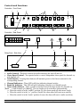
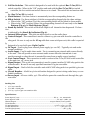
American DJ
®
User Instructions
Introduction:
Congratulations and thank you for purchasing the American DJ Light Copilot®. The Light Copilot is an eight channel controller with two separate chase zones. Each zone is switchable from an audio or a timed chase sequence. Chase intervals
vary from 0.1 seconds to 10 minutes. The controller has a built in microphone for easy audio chase sequences. Chases can
be made to run to sound via an internal microphone or and external RCA audio line input. Audio chase sensitivity is
adjustable by a rotary knob on the front panel. A “Latch” switch can override the chase function, to remain an individual
channel on while the other maintain their chase sequence. You can daisy chain up to three power packs per a controller
for easy installation and enhanced flexibility. The power pack uses high quality triacs for increased reliability. This unique
controller allows for a single power source i.e. the controller unit receives it’s power from the relay pack via the 9 pin com
cable.
Operating Instructions
Set-Up:
1. Connect the supplied 9 pin com cable from the out put of the controller unit to the input of the power pack.
2. Plug in the power pack to a standard AC outlet. Note: The controller unit does not come with an external power
supply, an external power supply is only needed if you are running two or three power packs.
3. If desired, plug in the Bar-T-Cue/FS remote foot switch control using the 1/4” stereo jack connection on the rear of
the controller unit (Bar-T-Cue/FS switch may be purchased as a separate option)
Basic Operation:
1.
2.
3.
4.
5.
6.
7.
After you have completed the set-up procedure, be sure main power is off and connect your desired lighting effects
to the power relay pack. Note: There are two sockets per a channel on the relay pack you can plug an effect into
either socket, or use both sockets to control two different lights to turn on at the same time.
Once you have connect your desired effects to the relay pack you can use the the “Latch buttons” to turn the fixtures
on and off, or use the “Flash Buttons” to momentarily turn fixture on and off.
The controller unit controls to separate 4 channel zones: Each zone may be controlled independently of each
other. The zones may chased through a build in timer or through an audio source (internal or external).
To run the fixtures to the chase sequence; Turn the on/off (Fig 10) switches to the on position for the fixture you
want to include in the chase sequence. Use the speed knobs (Fig. 3) in conjunction with the chase time switches
(Fig. 7) to adjust the chase speed to your ideal settings. See page 2 Chase/Audio Selector.
To run the fixtures to audio; Turn the on/off (Fig 10) switches to the on position for the fixture you want to chase to
audio. Use the audio knob (Fig. 2) to adjust the audio sensitivity to your ideal settings.
During the chase sequence or audio mode you can use the Latch or Flash Buttons, to manually override either the
chase sequence or the audio mode, and leave a fixture running.
You may use the Stand-By button to black out all controller functions and output
American DJ Supply®
Los Angeles Ca. Light Copilot Page 1
Controls and Functions:
Controller - Front Panel
2
1
3
AUDIO
4
SPEED
SPEED
CH1-4
CH5-8
5
6
POWER
1
American DJ®
STAND BY
8
7
12
11
10
9
Controller - Rear Panel
PIN
1
2
CH
VCC
4
3
3
4
5
6
7
8
9
2
1
8
7
6
5
CONTROL OUTPUT
13
17
18
DC IN
+9V~+12V
200MA MIN.
AUDIO IN
FOOT CONTROL
14
15
16
19
20
Relay Pack - Side View
AC 120~60Hz,15A
OUTPUT
INPUT
CIRCUIT BREAKER
AC POWER
1. Power Switch - Applies main power to the unit
2. Audio Control - This knob controls the audio sensitivity the unit will react to.
3. Chase Speed Control - Two sperate knobs to control independent chase speed for channels 1-4
and channels 5-8.
4. Latch Buttons - Pressing these buttons will maintain power to the fixture connected to the
corresponding channel.
5. Channel Indicators - These LED’s will glow indicating channel activity.
6. Stand-By Indicator - This LED will glow indicating controller is in Stand-By mode.
7. Chase Audio Selector - These 3 position switches control the chase modes for channels 1-4
(Bank
1) and channels 5-8 (Bank 2). The two banks can be controllers independently.
a. When the switch is in the “10MIN” position (Up) the chase speed will react more slowly.
b. When the switch is in the “x 1” position (Center) the chase speed will react more quickly.
c. When the switch is in the “Audio” position (Lower) the chase will react to audio sensitivity.
American DJ Supply® Los Angeles Ca. Light Copilot Page 2
8. Full On Switches - This switch is designed to be used with the optional Bar-T-Cue/FS foot
switch controller. When in the “ON” position and used with the Bar-T-Cue/FS foot switch
controller, the foot switch can turn all fixture on in a bank. This switch has no function without
the Bar-T-Cue/FS foot switch.
9. Flash Buttons - Use these button to momentarily turn the corresponding fixture on.
10. Effect Switch - Use these switches to link the corresponding channels the the chase settings.
a. When in the “ON” position (Top) the corresponding fixture will be linked to chase modes.
b. When in the “OFF” position (Lower) the corresponding channel will react only to the Latch
Buttons (Fig.4) and Flash Buttons (Fig.9).
11. Stand-By Switch - This switch will hold all output to all channels when depressed. It’s function
is indicated by the Stand-By Indicator (Fig.6).
12. Internal Microphone - This picks an audio signal to run the audio chase.
13. Control Output - This connection is used to connect a 9 pin com cable from the controller to
the
relay pack. Be sure to only use the LC-25 cable that comes with your unit, this cable is especially
designed to be used with your Light Copilot.
14. DC Input - Used to plug in an external power supply (9v~12v DC) - Typically not used under
normal conditions.
15. Audio Input - Used in audio chase mode - Use to connecting an external audio source directly
to the unit. This will provide a more accurate audio source when the internal mic is not
sensitive enough or when the unit is mounted far away from an audio source (speaker).
16. Foot Control Input - This connection is used to connect a Bar-T-Cue/FS foot switch controller
to the unit via a 1/4” stereo jack.
17. Signal Output - This 9 pin com connection is used to connect another LC-8SP relay pack to the
controller unit. Be sure to use only specified American DJ 9 pin com cables.
18. Signal Input - Used to link the controller unit with LC-8SP relay pack via a specified 9 pin com
cable.
19. Circuit Breaker - A built in 15A circuit breaker designed to protect wiring under heavy or overloaded conditions.
20.Power Input - AC 120v~60Hz, 15A - This will also power the controller unit through the 9 pin
com cable.
Packing List:
1. 1) LC-100 controller
2. 1) LC-8SP - Switch pack
3. 1) LC-25 - 25 foot 9 pin com extension cable
Specifications:
Power Input LC -100........................................................................................DC +9 ~ 12v, 200mA min.
Power Input LC -8SP................................................................................................AC 120v ~ 60Hz, 15A
Channel Output......................................................................................10A per channel, Total 15A max.
Circuit Breaker.......................................................................................................................................15A
LC-100 Dimensions..........................................................................................1 3/16”h x 19”w x 2 7/16”d
LC-8SP Dimensions..........................................................................................................4”h x 19”w x 4”d
Total Weight (System).............................................................................................................7lbs / 3.5Kg
American DJ Supply® Los Angeles Ca. Light Copilot Page 3