1
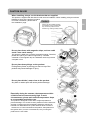
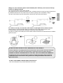
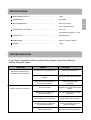
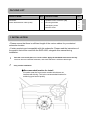
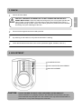
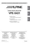
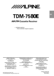
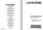
Owners Manual
a
SWD-1600
Class D Amplifier Active Subwoofer
Please follow these instructions for your safety
• Introduction:
Please read this owners manual thoroughly to familiarise yourself with each control and function. We at
Alpine hope that your new SWD-1600 will give you many years of listening enjoyment.
In case of problems when installing your SWD-1600, please contact your authorised Alpine dealer.
CAUTION
This symbol means important instructions.
Failure to heed them can result in serious injury or death.
DO NOT DISASSEMBLE OR ALTER. Doing so may result in an accident, fire or electric shock.
KEEP SMALL OBJECTS SUCH AS BOLTS OR SCREWS OUT OF THE REACH OF
CHILDREN. Swallowing them may result in serious injury. If swallowed, consult a doctor
immediately.
USE THE CORRECT AMPERE RATING WHEN REPLACING FUSES. Failure to do to may result
in fire or electric shock.
USE ONLY IN CARS WITH A 12 VOLT NEGATIVE GROUND. (Check with your dealer if you are
not sure.) Failure to do so may result in fire, etc.
BEFORE WIRING, DISCONNECT THE CABLE FROM THE NEGATIVE BATTERY TERMINAL.
Failure to do so may result in electric shock or injury due to electrical shorts.
DO NOT SPLICE INTO ELECTRICAL CABLES. Never cut away cable insulation to supply power
to other equipment. Doing so will exceed the current carrying capacity of the wire and result in fire
or electric shock.
DO NOT ALLOW CABLES TO BECOME ENTANGLED IN SURROUNDING OBJECTS. Arrange
the wiring and cables in compliance with the manual to prevent obstructions when driving. Cables
or wiring that obstruct or hang up on places such as the steering wheel, gear lever, brake pedals,
etc. can be extremely hazardous.
DO NOT DAMAGE PIPES OR WIRING WHEN DRILLING HOLES. When drilling holes in
the chassis for installation, take precautions so as not to contact, damage or obstruct pipes,
fuel lines, tanks or electrical wiring. Failure to take such precautions may result in fire.
EN
DO NOT USE BOLTS OR NUTS IN THE BRAKE OR STEERING SYSTEMS TO MAKE
GROUND CONNECTIONS. Bolts or nuts used for the brake, steering systems (or any other safety
related system), or any storage tanks should NEVER be used for installations or ground
connections. Using such parts could disable control of the vehicle and/or cause fire, etc.
HALT USE IMMEDIATLEY IF A PROBLEM APPEARS. Failure to do so may cause personal
injury or damage to the product. Return it to your Authorised Alpine Dealer or the nearest Alpine
Service Centre for repairing.
DO NOT OPERATE ANY FUNCTION THAT TAKES YOUR ATTENTION AWAY FROM SAFELY
DRIVING YOUR VEHICLE. Any function that requires your prolonged attention should only be
performed after coming to a complete stop. Always stop the vehicle in a safe location before
performing these functions, Failure to do so may result in an accident.
CAUTION
This symbol means important instructions.
Failure to heed them can result in injury or property damage
MAKE THE CORRECT CONNECTIONS. Failure to make the proper connections may result in fire
or product damage.
ROUTE THE WIRING TO ENSURE IT IS NOT CRIMPED OR PINCHED BY A SHARP METAL
EDGE. Route the cables and wiring away from moving parts (like the seat rails) or sharp or pointed
edges. This will prevent crimping and damage to the wiring. If wiring passes through a hole in
metal, use a rubber grommet to prevent the wires insulation from being cut by the metal edge of
the hole.
DO NOT BLOCK VENTS OR RADIATOR PANELS. Doing so may cause heat to build up inside
and may result in fire.
USE SPECIFIED ACCESSORY PARTS AND INSTALL THEM SECURLEY. Be sure to use only
the specified accessory parts. Use of other than designated parts may damage this unit internally
or may not securely install the unit in place. This may cause parts to become loose resulting in
hazards or product failure.
DO NOT INSTALL IN LOCATIONS WITH HIGH MOISTURE OR DUST. Avoid installing the unit in
locations with high incidence of moisture or dust. Moisture or dust that penetrates into this unit may
result in product failure.
HAVE THE WIRING AND INSTALLATION DONE BY AN EXPERT. The wiring and installation of
this unit requires special technical skill and experience. To ensure safety, always contact the
dealer where you purchased this product to have the work done.
KEEP THE VOLUME AT A LEVEL WHERE YOU CAN STILL HEAR OUTSIDE NOISE WHILE
DRIVING. Failure to do so may result in an accident.
USE THIS PRODUCT FOR MOBILE 12V APPLICATIONS. Use for other than its designed
application may result in fire, electric shock or injury.
EN
CAUTION IN USE
When installing, always use the brackets that are supplied.
This product is supplied with brackets for safe use and installation. When installing, always use these
brackets to firmly fix the product into place.
For further information, please refer to
Caution!
the “installation” page.
Always use the brackets supplied
for installation. Using anything else
may cause the product to move
while driving, creating a safety hazard.
Do not place items with magnetic strips, such as credit
cards / store cards nearby.
This product is fitted with a contains a powerful magnet. Therefore,
please don’t place your wallet or bags near by. The data
contained on the magnetic strip of credit/store cards may become
corrupted or lost.
Do not place heavy things on the product.
Putting heavy items or placing your feet on top of the
product may cause damage or injury.
Do not place drinks / water close to the product.
Any drink or water spills will cause product damage.
Especially during the summer, the temperature within
a vehicle can become extremely high. In such
circumstances, please wait until the temperature drops
to a reasonable level before use.
This product is designed to shut down at high temperature to
prevent damage. If no sound is heard, please turn off the head unit
and then on again once the temperature inside the vehicle has
lowered to a reasonable level. (If the head unit does not have a
“remote turn on” lead connected to the product, then please turn
the ignition off/on.) In such circumstances, carry on using the
product as it is not a fault.
EN
Always use the extension power lead included (with 12A fuse), and connect directly
to the +ve battery terminal.
Only use the extension power cable included.
Also, please ensure to connect this directly to the +ve battery terminal. Should you feed off power from
the standard vehicle loom, the product may not function properly due to insufficient voltage.
The high current draw may also overheat the vehicle loom and create a fire hazard.
EN
It is vital to securely connect the earth lead to a metal part of the vehicle chassis.
Please ensure to connect the earth lead to a metal part of the vehicle chassis with a screw.
If the grounding of the earth lead is insufficient, the product may malfunction.
Any paint or coating on the earth point of the vehicle chassis should be removed with a file to enable a
good connection.
DO NOT EXCEED THE INPUT LEVEL SPECIFIED FOR THIS PRODUCT.
If there is distortion or a popping noise from the subwoofer, the input level is too high. Prolonged
use in this condition will result in the deterioration of performance and may lead to damage..
DAMGE CAUSED BY EXCESSIVE INPUT LEVEL WILL NOT BE COVERED BY WARRANTY.
If reducing the gain to prevent distortion leads to insufficient output, please install the
subwoofer closer to the listener. As a general rule, halving the distance will result in 4
times the volume.
DO NOT USE A MOBILE PHONE NEAR THIS PRODUCT.
Use of a mobile phone may cause interference and noise.
SPECIFICATIONS
MAX POWER OUTPUT……………………………………………
150W
CROSSOVER………………………………………………………
60~160Hz
INPUT IMPEDANCE……………………..…………………………
22k Ω (Line Input)
36k Ω (Speaker Input)
OPERATIONAL VOLTAGE……………………..…………………
DC 14.4V
(Operational between: 11~16V)
EARTH TYPE……………………..………………...………………
Negative Earth
DIMENSIONS……...……………………..…………………………
282mm x 195mm x 92mm
WEIGHT……...……………………..………………………………
4.0kg
TROUBLESHOOTING
If you have a problem with the product then please check the following
before taking for repair.
SYMPTOMS
Unit does not operate. (For
example if the fuse is blown)
There is power but no sound.
REASON
SOLUTION
The head unit is not powered up.
Power up the head unit.
Earth lead is not connected
properly.
Check the earth lead connection
The power lead to the battery is
not connected properly.
Check the battery lead
connection
The fuse is blown.
Replace with a fuse of the correct
rating.
Remote turn on lead is not
connected properly.
Check the remote turn on lead
connection
RCA leads are not connected.
Connect RCA leads correctly.
Speaker level input cables are
not connected properly
Check the speaker level input
cable connections.
The gain is not at the correct
level for the system.
Adjust the gain setting to an
appropriate level for the system.
EN
PACKING LIST
PRODUCT NAME
QTY
PRODUCT NAME
QTY
Connector
1
Speaker to RCA connector (3M)
2
Power lead extension cable (2.5M)
1
Mounting brackets
3
Self tapping screw
6
Machine screw
3
1. INSTALLATION
• Please ensure that there is sufficient length of the various cables for your desired
subwoofer location.
• Certain products are incompatible with this subwoofer. Please read the instructions of
the product that will be used with the SWD-1600, alongside this manual during
installation.
1
Park the car at a safe place, on a level surface. Apply the handbrake and remove the key.
Work out where to install the subwoofer, and check that there is sufficient cable length.
2
Carry out the Installation.
● Recommended location for install
A location near the front centre console which does not
interfere with driving. This is the recommended location for
achieving good sound quality.
EN
1
Carefully consider all installation possibilities and locations.
2
Decide where to install the subwoofer.
Attach the brackets with the supplied machine screws.
• The brackets can be attached for horizontal or vertical mounting.
Please attach the brackets accordingly.
EN
3
Mark the self tapping screw locations in your car.
4
Drill a hole 3mm or less in diameter.
5
Secure the subwoofer to the car with the self tapping screws.
6
Connect the ground lead securely and safely to a bare metal spot (remove any paint or
coating if necessary) of the car chassis.
Horizontal mounting
Select the appropriate
insert depending on
the position of the
install location.
Vertical mounting
Machine Screw
Insert
Brackets
Machine Screw
WARNING - DO NOT DAMAGE PIPE OR WIRING WHEN DRILLING HOLES. When drilling
holes in the chassis for installation, take precautions so as not to contact, damage or obstruct pipes,
fuel lines, tanks or electrical wiring. Failure to take such precautions may result in fire.
Self tapping screw
EN
Machine Screw
Brackets
Floor mat
on the vehicle
2. CONNECTION
1
Disconnect the cable from the negative terminal of the car battery.
2
Connect
EN
• CONNECTIONS FOR RCA INPUT
RCA lead
(sold separately)
Pre-out
Head Unit
Blue/White
Remote turn on
Remote turn on
Connect to the ACC line if the
head unit has no remote on lead.
Black
Ground connection
Yellow
Yellow
FUSE
Battery extension lead
Connect the ground lead securely
and safely to a metal part of the
vehicle chassis.
●Always use the extension
cable supplied for connection
to the +ve battery terminal.
●DO NOT connect this lead to
the head unit.
●DO NOT modify this cable.
It may cause malfunction and
damage to the product.
Memo
• This product cannot be used with cars fitted with a common negative speaker system.
•To prevent external noise from entering the audio system:
• Locate the unit and route the leads at least 10 cm away from the car harness.
• Keep the battery power leads as far away from other leads as possible.
• Connect the ground lead securely and safely to a bare metal spot (remove the coating if
necessary) of the car chassis.
• If you add an optional noise suppressor, connect it as far away from the unit as possible. Your
Alpine Dealer carries various Alpine noise suppressors, contact them for further information.
• Your Alpine Dealer knows best about noise prevention measures so consult your dealer for
further information.
• Make all connections securely.
• Any unused connections should be insulated with electrical insulation tape.
• On cars fitted with computers and other such devices (e.g. head units with
security code), you may loose the memory when disconnecting the negative lead.
EN
• CONNECTIONS FOR SPEAKER LEVEL INPUT
If your head unit does not have this lead,
then please connect to the the ACC lead of the vehicle.
The lead that supplies power when the key is
at the ACC position.
Head Unit
Connect the ground lead
securely and safely to a
metal part of the vehicle
chassis.
Battery extension lead
Remote turn on
- +
Black
Ground connection
Yellow Yellow
- +
Left Speaker Output
Left Speaker Output
Right Speaker Output
Right Speaker Output
FUSE(12A)
Blue/White
Please connect to either the
rear or front speaker output leads.
-Caution
The output of the subwoofer will be
affected by the head unit fader settings.
●Always use the extension
EN
cable supplied for
connection to the +ve
battery terminal.
●DO NOT connect this lead
to the head unit.
●DO NOT modify this cable.
It may cause malfunction and
damage to the product.
Speaker to RCA input lead
White
Green
Left Speaker
Green/Black
Speaker to RCA input lead
Red
Violet
Right Speaker
Violet/Black
CAUTION
– PLEASE FOLLOW THE INSTRUCTIONS CAREFULLY.
Failure to do so may result in fire, accident or electrical shock.
WARNING
- DO NOT USE BOLTS OR NUTS IN THE BRAKE OR STEERING SYSTEMS TO MAKE GROUND CONNECTIONS.
Bolts or nuts used for the brake or steering systems (or any other safety related system), or tanks should NEVER be used for
installations or ground connections. Using such parts could disable control of the vehicle and cause fire, etc.
Type of Lead
Additional Information
Remote turn on lead
Connect to the remote turn on lead of the head unit.
• If your head unit does not have this lead, then please connect to the the ACC lead of the vehicle. The lead that
supplies power when the key is at the ACC position.
Ground lead
Battery power lead
Attach securely and safely to a bare metal spot of the car’s chassis.
Connect directly to the positive terminal of the car’s battery.
3. CHECK
1
Secure all loose cables.
CAUTION - ARRANGE THE WIRING SO IT IS NOT CRIMPED OR PINCHED BY A
SHARP METAL EDGE. Route the cables and wiring away from moving parts (like the seat
rails) or sharp or pointed edges. This will prevent crimping and damage to the wiring. If
wiring passes through a hole in metal, use a rubber grommet to prevent the wires insulation
from being cut by the metal edge of the hole.
2
Reconnect the negative lead to the battery terminal
3
By switching on the head unit, verify that the subwoofer is working.
4
Check that all electrical functions of the car are operational. (lights, indicators, horn etc.)
4. ADJUSTMENT
PHASE SELECTOR
LOW PASS FILTER ADJUSTMENT
GAIN ADJUSTMENT
CAUTION
DO NOT EXCEED THE INPUT LEVEL SPECIFIED FOR THIS PRODUCT.
If there is distortion or a popping noise from the subwoofer the input level is too high.
If the subwoofer has prolonged use in this condition, this may result in deterioration of
performance or may cause damage to the subwoofer.
EN
4. ADJUSTMENT
1.
Set the gain to MIN, Phase to NORM, LPF to CENTER before switching on the system.
2.
Set the Bass/Treble adjustment to zero on the head unit. Set the volume to your average
listening level. It may help to use a music source that is familiar.
3.
Next, gradually increase the gain level. Increase the level to the point where the sound of
your system, as a whole, is balanced. If the gain level is set too high, the subwoofer may
begin to distort. Distortion may also occur if the volume is set too high on the head unit.
Check that the other speakers have not begun to distort, before proceeding with the
adjustment. If the entire speaker system in the car is distorting, reduce the volume of the
head unit.
4.
Once the gain has been set, adjust the L.P.F (Low Pass Filter) at a frequency which
compliments your speaker system. (We recommend using CENTER as a starting point.)
5.
Adjusting the L.P.F will change the output volume of the subwoofer. Repeat procedures 3
and 4 until the ideal setting is found.
The final adjustment is the PHASE of the subwoofer. While sitting in the driver’s seat and with
music playing, switch between NORM and REV. Select the setting which sounds better – The
ideal PHASE setting varies from car to car, depending on the location of the subwoofer and
the acoustic characteristics of the vehicle interior.
6.
ALPINE ELECTRONICS MARKETING, INC.
1-1-8 Nishi Gotanda,
Shinagawa-ku,
Tokyo 141-0031, Japan
Phone 03-5496-8231
ALPINE ELECTRONICS OF AMERICA, INC.
19145 Gramercy Place, Torrance,
California 90501, U.S.A.
Phone 1-800-ALPINE-1 (1-800-257-4631)
ALPINE ELECTRONICS OF CANADA, INC.
7300 Warden Ave., Suite 203, Markham,
Ontario L3R 9Z6, Canada
Phone 1-800-ALPINE-1 (1-800-257-4631)
ALPINE ELECTRONICS OF AUSTRALIA PTY. LTD.
6-8 Fiveways Boulevarde Keysborough,
Victoria 3173, Australia
Phone 03-9769-0000
ALPINE ELECTRONICS GmbH
Frankfurter Ring 117,
80807 München, Germany
Phone 089-3242640
ALPINE ELECTRONICS OF U.K. LTD.
Alpine House
Fletchamstead Highway, Coventry CV4 9TW, U.K.
Phone 0870-33 33 763
ALPINE ELECTRONICS FRANCE S.A.R.L.
(RCS PONTOISE B 338 101 280)
98, Rue de la Belle Etoile, Z.I. Paris Nord Il,
B.P. 50016, 95945 Roissy Charles de Gaulle
Cedex, France
Phone 01-48638989
ALPINE ITALIA S.p.A.
Viale C. Colombo 8, 20090 Trezzano Sul
Naviglio (MI), Italy
Phone 02-484781
ALPINE ELECTRONICS DE ESPAÑA, S.A.
Portal de Gamarra 36, Pabellón, 32
01013 Vitoria (Alava)-APDO 133, Spain
Phone 945-283588
EN