1
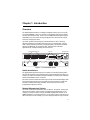
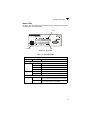
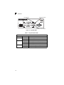
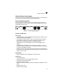
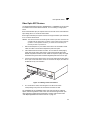
Part No. 060190-10, Rev. A
December 2003
OmniStack® 6300-24
Getting Started Guide
An Alcatel service agreement brings your company the assurance of 7x24 no-excuses
technical support. You’ll also receive regular software updates to maintain and
maximize your Alcatel product’s features and functionality and on-site hardware
replacement through our global network of highly qualified service delivery partners.
Additionally, with 24-hour-a-day access to Alcatel’s Service and Support web page,
you’ll be able to view and update any case (open or closed) that you have reported to
Alcatel’s technical support, open a new case or access helpful release notes, technical
bulletins, and manuals. For more information on Alcatel’s Service Programs, see our
web page at www.ind.alcatel.com, call us at 1-800-995-2696, or email us at
[email protected].
This Manual documents OmniStack 6300-24 hardware and software.
The functionality described in this Manual is subject to change without notice.
Copyright© 2003 by Alcatel Internetworking, Inc. All rights reserved. This document may not be
reproduced in whole or in part without the express written permission of Alcatel Internetworking,
Inc.
Alcatel®and the Alcatel logo are registered trademarks of Compagnie Financiére Alcatel, Paris,
France. OmniSwitch® and OmniStack® are registered trademarks of Alcatel Internetworking, Inc.
Omni Switch/Router™, SwitchExpertSM, the Xylan logo are trademarks of Alcatel Internetworking,
Inc. All other brand and product names are trademarks of their respective companies.
26801 West Agoura Road
Calabasas, CA 91301
(818) 880-3500 FAX (818) 880-3505
[email protected]
US Customer Support-(800) 995-2696
International Customer Support-(818) 878-4507
Internet-http://eservice.ind.alcatel.com
Warning
This equipment has been tested and found to comply with the limits for Class B digital
device pursuant to Part 15 of the FCC Rules. These limits are designed to provide
reasonable protection against harmful interference when the equipment is operated in a
commercial environment. This equipment generates, uses, and can radiate radio
frequency energy and, if not installed and used in accordance with the instructions in
this guide, may cause interference to radio communications. Operation of this equipment
in a residential area is likely to cause interference, in which case the user will be required
to correct the interference at his own expense.
The user is cautioned that changes and modifications made to the equipment without
approval of the manufacturer could void the user’s authority to operate this equipment.
It is suggested that the user use only shielded and grounded cables to ensure compliance
with FCC Rules.
This digital apparatus does not exceed the Class B limits for radio noise emissions from
digital apparatus set out in the radio interference regulations of the Canadian
department of communications.
Le present appareil numerique níemet pas de bruits radioelectriques depassant les
limites applicables aux appareils numeriques de la Class B prescrites dans le reglement
sur le brouillage radioelectrique edicte par le ministere des communications du Canada.
Compliances and Safety Warnings
FCC - Class B
This equipment has been tested and found to comply with the limits for a Class B digital device,
pursuant to Part 15 of the FCC Rules. These limits are designed to provide reasonable protection
against harmful interference in a residential installation. This equipment generates, uses and can
radiate radio frequency energy and, if not installed and used in accordance with instructions, may
cause harmful interference to radio communications. However, there is no guarantee that the interference will not occur in a particular installation. If this equipment does cause harmful interference
to radio or television reception, which can be determined by turning the equipment off and on, the
user is encouraged to try to correct the interference by one or more of the following measures:
• Reorient the receiving antenna
• Increase the separation between the equipment and receiver
• Connect the equipment into an outlet on a circuit different from that to which the receiver is
connected
• Consult the dealer or an experienced radio/TV technician for help
EC Conformance Declaration - Class B
SMC contact for these products in Europe is:
SMC Networks Europe,
Edificio Conata II,
Calle Fructuós Gelabert 6-8, 2o, 4a,
08970 - Sant Joan Despí,
Barcelona, Spain.
This information technology equipment complies with the requirements of the Council
Directive 89/336/EEC on the Approximation of the laws of the Member States relating to
Electromagnetic Compatibility and 73/23/EEC for electrical equipment used within certain
voltage limits and the Amendment Directive 93/68/EEC. For the evaluation of the
compliance with these Directives, the following standards were applied:
RFI Emission:
• Limit class B according to EN 55022:1998, IEC 60601-1-2 (EMC,
medical)
• Limit class A for harmonic current emission according to
EN 61000-3-2/1995
• Limitation of voltage fluctuation and flicker in low-voltage supply system
according to EN 61000-3-3/1995
Immunity:
• Product family standard according to EN 55024:1998
• Electrostatic Discharge according to EN 61000-4-2:1995
(Contact Discharge: ±4 kV, Air Discharge: ±8 kV)
• Radio-frequency electromagnetic field according to EN 61000-4-3:1996
(80 - 1000 MHz with 1 kHz AM 80% Modulation: 3 V/m)
• Electrical fast transient/burst according to EN 61000-4-4:1995 (AC/DC
power supply: ±1 kV, Data/Signal lines: ±0.5 kV)
• Surge immunity test according to EN 61000-4-5:1995
(AC/DC Line to Line: ±1 kV, AC/DC Line to Earth: ±2 kV)
v
• Immunity to conducted disturbances, Induced by radio-frequency fields:
EN 61000-4-6:1996 (0.15 - 80 MHz with
1 kHz AM 80% Modulation: 3 V/m)
• Power frequency magnetic field immunity test according to
EN 61000-4-8:1993 (1 A/m at frequency 50 Hz)
• Voltage dips, short interruptions and voltage variations immunity test
according to EN 61000-4-11:1994 (>95% Reduction @10 ms, 30%
Reduction @500 ms, >95% Reduction @5000 ms)
LVD:
• EN 60950 (A1/1992; A2/1993; A3/1993; A4/1995; A11/1997)
MDD:
• IEC 60601-1
Industry Canada - Class B
This digital apparatus does not exceed the Class B limits for radio noise emissions from digital
apparatus as set out in the interference-causing equipment standard entitled “Digital Apparatus,”
ICES-003 of the Department of Communications.
Cet appareil numérique respecte les limites de bruits radioélectriques applicables aux appareils
numériques de Classe B prescrites dans la norme sur le matériel brouilleur: “Appareils
Numériques,” NMB-003 édictée par le ministère des Communications.
Japan VCCI Class B
vi
Safety Compliance
Warning: Fiber Optic Port Safety
CLASS I
LASER DEVICE
When using a fiber optic port, never look at the transmit laser while it is
powered on. Also, never look directly at the fiber TX port and fiber cable
ends when they are powered on.
Avertissment: Ports pour fibres optiques - sécurité sur le plan optique
DISPOSITIF LASER
DE CLASSE I
Ne regardez jamais le laser tant qu'il est sous tension. Ne regardez
jamais directement le port TX (Transmission) à fibres optiques et les
embouts de câbles à fibres optiques tant qu'ils sont sous tension.
Warnhinweis: Faseroptikanschlüsse - Optische Sicherheit
Niemals ein Übertragungslaser betrachten, während dieses
eingeschaltet ist. Niemals direkt auf den Faser-TX-Anschluß
und auf die Faserkabelenden schauen, während diese
eingeschaltet sind.
LASERGERÄT
DER KLASSE I
Underwriters Laboratories Compliance Statement
Important! Before making connections, make sure you have the correct cord set. Check
it (read the label on the cable) against the following:
Operating Voltage Electrical Cord Requirements
Operating Voltage
120 Volts
Cord Set Specifications
UL Listed/CSA Certified Cord Set
Minimum 18 AWG
Type SVT or SJT three conductor cord
Maximum length of 15 feet
Parallel blade, grounding type attachment plug rated 15A, 125V
240 Volts (Europe only)
Cord Set with H05VV-F cord having three conductors with
minimum diameter of 0.75 mm2
IEC-320 receptacle
Male plug rated 10A, 250V
The unit automatically matches the connected input voltage. Therefore, no additional
adjustments are necessary when connecting it to any input voltage within the range
marked on the rear panel.
vii
Wichtige Sicherheitshinweise (Germany)
1.
Bitte lesen Sie diese Hinweise sorgfältig durch.
2.
Heben Sie diese Anleitung für den späteren Gebrauch auf.
3.
Vor jedem Reinigen ist das Gerät vom Stromnetz zu trennen. Verwenden Sie keine
Flüssigoder Aerosolreiniger. Am besten eignet sich ein angefeuchtetes Tuch zur
Reinigung.
4.
Die Netzanschlu ßsteckdose soll nahe dem Gerät angebracht und leicht zugänglich sein.
5.
Das Gerät ist vor Feuchtigkeit zu schützen.
6.
Bei der Aufstellung des Gerätes ist auf sicheren Stand zu achten. Ein Kippen oder Fallen
könnte Beschädigungen hervorrufen.
7.
Die Belüftungsöffnungen dienen der Luftzirkulation, die das Gerät vor Überhitzung schützt.
Sorgen Sie dafür, daß diese Öffnungen nicht abgedeckt werden.
8.
Beachten Sie beim Anschluß an das Stromnetz die Anschlußwerte.
9.
Verlegen Sie die Netzanschlußleitung so, daß niemand darüber fallen kann. Es sollte auch
nichts auf der Leitung abgestellt werden.
10. Alle Hinweise und Warnungen, die sich am Gerät befinden, sind zu beachten.
11. Wird das Gerät über einen längeren Zeitraum nicht benutzt, sollten Sie es vom Stromnetz
trennen. Somit wird im Falle einer Überspannung eine Beschädigung vermieden.
12. Durch die Lüftungsöffnungen dürfen niemals Gegenstände oder Flüssigkeiten in das Gerät
gelangen. Dies könnte einen Brand bzw. elektrischen Schlag auslösen.
13. Öffnen sie niemals das Gerät. Das Gerät darf aus Gründen der elektrischen Sicherheit nur
von authorisiertem Servicepersonal geöffnet werden.
14. Wenn folgende Situationen auftreten ist das Gerät vom Stromnetz zu trennen und von einer
qualifizierten Servicestelle zu überprüfen:
a.
b.
c.
d.
Netzkabel oder Netzstecker sind beschädigt.
Flüssigkeit ist in das Gerät eingedrungen.
Das Gerät war Feuchtigkeit ausgesetzt.
Wenn das Gerät nicht der Bedienungsanleitung entsprechend funktioniert oder Sie mit
Hilfe dieser Anleitung keine Verbesserung erzielen.
e. Das Gerät ist gefallen und/oder das Gehäuse ist beschädigt.
f. Wenn das Gerät deutliche Anzeichen eines Defektes aufweist.
15. Zum Netzanschluß dieses Gerätes ist eine geprüfte Leitung zu verwenden. Für einen
Nennstrom bis 6A und einem Gerätegewicht größer 3kg ist eine Leitung nicht leichter als
H05VV-F, 3G, 0.75mm2 einzusetzen.
Der arbeitsplatzbezogene Schalldruckpegel nach DIN 45 635 Teil 1000 beträgt 70dB(A) oder
weniger.
viii
Warnings and Cautionary Messages
Warning:
This product does not contain any servicable user parts.
Warning:
When connecting this device to a power outlet, connect the field ground lead
on the tri-pole power plug to a valid earth ground line to prevent electrical
hazards.
Warning:
This switch uses lasers to transmit signals over fiber optic cable. The lasers
are compliant with the requirements of a Class 1 Laser Product and are
inherently eye safe in normal operation. However, you should never look
directly at a transmit port when it is powered on.
Caution:
Wear an anti-static wrist strap or take other suitable measures to prevent
electrostatic discharge when handling this equipment.
Caution:
Do not plug a phone jack connector in the RJ-45 port. This may damage this
device. Les raccordeurs ne sont pas utilisé pour le système téléphonique!
Caution:
Use only twisted-pair cables with RJ-45 connectors that conform to FCC
standards.
Environmental Statement
The manufacturer of this product endeavours to sustain an environmentally-friendly policy
throughout the entire production process. This is achieved though the following means:
• Adherence to national legislation and regulations on environmental production
standards.
• Conservation of operational resources.
• Waste reduction and safe disposal of all harmful un-recyclable by-products.
• Recycling of all reusable waste content.
• Design of products to maximize recyclables at the end of the product’s life span.
• Continual monitoring of safety standards.
End of Product Life Span
This product is manufactured in such a way as to allow for the recovery and disposal of all
included electrical components once the product has reached the end of its life.
Manufacturing Materials
There are no hazardous nor ozone-depleting materials in this product.
Documentation
All printed documentation for this product uses biodegradable paper that originates from
sustained and managed forests. The inks used in the printing process are non-toxic.
ix
Purpose
This guide details the hardware features of the OmniStack 6300 switch, including Its
physical and performance-related characteristics, and how to install the switch.
Related Publications
The following publication gives specific information on how to operate and use the
management functions of the switch:
The OmniStack 6300 User Guide
Also, as part of the switch’s firmware, there is an online web-based help that describes all
management related features.
x
Contents
Chapter 1: Introduction
Overview
Switch Architecture
Network Management Options
Description of Hardware
10/100/1000BASE-T Ports
SFP Slots
Status LEDs
Optional Backup Power Supply
Power Supply Receptacles
Features and Benefits
Connectivity
Expandability
Performance
Management
1-1
1-1
1-1
1-1
1-2
1-2
1-2
1-3
1-5
1-5
1-5
1-5
1-5
1-5
1-6
Chapter 2: Network Planning
Introduction to Switching
Application Examples
Collapsed Backbone
Network Aggregation Plan
Remote Connection with Fiber Cable
Making VLAN Connections
Application Notes
2-1
2-1
2-2
2-2
2-3
2-4
2-5
2-6
Chapter 3: Installing the Switch
Selecting a Site
Ethernet Cabling
Equipment Checklist
Package Contents
Optional Rack-Mounting Equipment
Mounting
Rack Mounting
Desktop or Shelf Mounting
Installing an Optional SFP Transceiver into the Switch
Connecting to a Power Source
Connecting to the Console Port
Wiring Map for Serial Cable
3-1
3-1
3-1
3-2
3-2
3-2
3-3
3-3
3-4
3-5
3-5
3-6
3-7
Chapter 4: Making Network Connections
Connecting Network Devices
4-1
4-1
xi
Contents
Twisted-Pair Devices
Cabling Guidelines
Connecting to PCs, Servers, Hubs and Switches
Network Wiring Connections
Fiber Optic SFP Devices
Connectivity Rules
1000BASE-T Cable Requirements
1000 Mbps Gigabit Ethernet Collision Domain
100 Mbps Fast Ethernet Collision Domain
10 Mbps Ethernet Collision Domain
Cable Labeling and Connection Records
4-1
4-1
4-1
4-2
4-3
4-4
4-4
4-4
4-5
4-5
4-6
Appendix A: Troubleshooting
Diagnosing Switch Indicators
Power and Cooling Problems
Installation
In-Band Access
A-1
A-1
A-1
A-1
A-1
Appendix B: Cables
Twisted-Pair Cable and Pin Assignments
10BASE-T/100BASE-TX Pin Assignments
1000BASE-T Pin Assignments
Fiber Standards
B-1
B-1
B-1
B-2
B-3
Appendix C: Specifications
Compliances
C-1
C-2
Glossary
Index
xii
Tables
Table 1-1.
Table 1-2.
Table 3-1.
Table 4-1.
Table 4-2.
Table 4-3.
Table 4-4.
Table 4-5.
Table A-1.
Table B-1.
Table B-2.
Port Status LEDs
System Status LEDs
Serial Cable Wiring
Maximum 1000BASE-T Gigabit Ethernet Cable Length
Maximum 1000BASE-SX Gigabit Ethernet Cable Lengths
Maximum 1000BASE-LX Gigabit Ethernet Cable Length
Maximum Fast Ethernet Cable Lengths
Maximum Ethernet Cable Length
Troubleshooting Chart
10/100BASE-TX MDI and MDI-X Port Pinouts
1000BASE-T MDI and MDI-X Port Pinouts
1-3
1-4
3-7
4-4
4-4
4-4
4-5
4-5
A-1
B-2
B-2
xi
Tables
xii
Figures
Figure 1-1.
Figure 1-2.
Figure 1-3.
Figure 1-4.
Figure 2-1.
Figure 2-2.
Figure 2-3.
Figure 2-4.
Figure 3-1.
Figure 3-2.
Figure 3-3.
Figure 3-4.
Figure 3-5.
Figure 3-6.
Figure 3-7.
Figure 4-1.
Figure 4-2.
Figure 4-3.
Figure B-1.
Front and Rear Panels
Port LEDs
System LEDs
Power Supply Receptacle
Collapsed Backbone
Network Aggregation Plan
Remote Connection with Fiber Cable
Making VLAN Connections
RJ-45 Connections
Attaching the Brackets
Installing the Switch in a Rack
Attaching the Adhesive Feet
Inserting an SFP Transceiver into a Slot
Power Receptacle
Serial Port (DB-9 DTE) Pin-Out
Making Twisted-Pair Connections
Network Wiring Connections
Making SC Port Connections
RJ-45 Connector Pin Numbers
1-1
1-3
1-4
1-5
2-2
2-3
2-4
2-5
3-2
3-3
3-4
3-4
3-4
3-6
3-6
4-1
4-2
4-3
B-1
xiii
Figures
xiv
Chapter 1: Introduction
Overview
The Gigabit Ethernet Switch is an intelligent multilayer switch (Layer 2 and 4) with
24 10/100/1000BASE-T ports, four of which are combination ports that are shared
with four SFP transceiver slots. There is also an SNMP-based management agent
embedded on the main board. This agent supports both in-band and out-of-band
access for managing the switch.
This switch provides a broad range of powerful features for Layer 2 switching,
delivering reliability and consistent performance for your network traffic. It brings
order to poorly performing networks by segregating them into separate broadcast
domains with IEEE 802.1Q compliant VLANs, and empowers multimedia
applications with multicast switching and CoS services.
10/100/1000 Mbps RJ-45 Ports
System Indicators
SFP Slots
1
3
5
7
9
11
13
15
17
19
21
OmniStack
6300-24
23
1000=Green 10/100=Yellow
21
22
23
24
1
2
3
4
5
6
7
8
9
10
11
12
13
14
15
16
17
18
19
20
21
22
Link/
Power
FDX
Diag
Link/
BPS
23 Act
24 Act
Console
FDX
2
4
6
8
10
12
14
16
18
20
22
24
Port Status Indicators
Redundant Power socket
Power Socket
Console Port
100-240V~, 50-60Hz 2A
BPS
DC IN
12V 8.5A
Figure 1-1. Front and Rear Panels
Switch Architecture
The Gigabit Ethernet Switch employs a wire-speed, non-blocking switching fabric.
This permits simultaneous wire-speed transport of multiple packets at low latency on
all ports. This switch also features full-duplex capability on all ports, which effectively
doubles the bandwidth of each connection.
The switch uses store-and-forward switching to ensure maximum data integrity. With
store-and-forward switching, the entire packet must be received into a buffer and
checked for validity before being forwarded. This prevents errors from being
propagated throughout the network.
Network Management Options
This switch contains a comprehensive array of LEDs for “at-a-glance” monitoring of
network and port status. It also includes a management agent that allows you to
configure or monitor the switch using its embedded management software, or via
SNMP applications. To manage the switch, you can make a direct connection to the
RS-232 console port (out-of-band), or you can manage the switch through a network
1-1
1
Introduction
connection (in-band) using Telnet, the on-board Web agent, or Windows-based
network management software.
For a detailed description of the switch’s advanced features, refer to the User Guide.
Description of Hardware
10/100/1000BASE-T Ports
These ports are RJ-45 ports that operate at 10 Mbps or 100 Mbps, half or full duplex,
or at 1000 Mbps, full duplex. Because all ports on this switch support automatic MDI/
MDI-X operation, you can use straight-through cables for all network connections to
PCs or servers, or to other switches or hubs. (See “1000BASE-T Pin Assignments”
on page B-2.)
Each of these ports support auto-negotiation, so the optimum transmission mode
(half or full duplex), and data rate (10, 100, or 1000 Mbps) can be selected
automatically. If a device connected to one of these ports does not support
auto-negotiation, the communication mode of that port can be configured manually.
Each port also supports auto-negotiation of flow control, so the switch can
automatically prevent port buffers from becoming saturated.
SFP Slots
The Small Form Factor Pluggable (SFP) transceiver slots are shared with four of the
RJ-45 ports (Ports 21~24). In its default configuration, if an SFP transceiver
(purchased separately) is installed in a slot and has a valid link on its port, the
associated RJ-45 port is disabled and cannot be used. The switch can also be
configured to force the use of an RJ-45 port or SFP slot, as required.
1-2
Description of Hardware
1
Status LEDs
The LEDs, which are located on the front panel for easy viewing, are shown below
and described in the following table.
Link/Act
BPS
FDX
SFP LEDs
Figure 1-2. Port LEDs
Table 1-1. Port Status LEDs
Port Status LEDs
LED
Condition
Status
On Green
Communications have been set to 1000 Mbps.
On Yellow
Communications have been set to 10/100 Mbps.
RJ-45 Ports
Link/Act.
FDX
Flashing Green
Traffic is passing through the port at 1000 Mbps.
Flashing Yellow
Traffic is passing through the port at 10/100 Mbps.
Green
Communications have been set to full duplex.
Off
Communications have been set to half duplex.
SFP Transceiver Slots
(Ports 21-24)
On Green
An SFP transceiver port has established a valid 1000 Mbps
network connection. The associated RJ-45 port is disabled.
Off
An SFP transceiver port has no valid link, or the link has
failed. The associated RJ-45 port is enabled.
1-3
1
Introduction
Power Indicator
Diagnostic Indicator
BPS
Redundant Power Indicator
Figure 1-3. System LEDs
Table 1-2. System Status LEDs
System Status LEDs
LED
Condition
Power
On Green
Switch is receiving power.
Off
Power off or failure.
Flashing Green
System self-diagnostic test in progress.
Diag
BPS
1-4
Status
On Green
System self-diagnostic test successfully completed.
On Red
System self-diagnostic test has failed.
On Green
The Backup Power Supply is receiving power.
Off
The Backup Power Supply is off.
Features and Benefits
1
Optional Backup Power Supply
The switch supports an optional Backup Power Supply (BPS), that can supply power
to the switch in the event of failure of the internal power supply.
Power Supply Receptacles
There are two power receptacles on the rear panel of the switch. The standard
power receptacle is for the AC power cord. The receptacle labeled “BPS” is for the
optional Backup Power Supply.
100-240V~, 50-60Hz 2A
BPS
DC IN
12V 8.5A
Figure 1-4. Power Supply Receptacle
Features and Benefits
Connectivity
• 24 dual-speed ports for easy Gigabit Ethernet integration and for protection of your
investment in legacy LAN equipment.
• Auto-negotiation enables each RJ-45 port to automatically select the optimum
communication mode (half or full duplex) if this feature is supported by the
attached device; otherwise the port can be configured manually.
• Independent RJ-45 10/100/1000BASE-T ports with auto MDI/MDI-X pinout
selection.
• Unshielded (UTP) cable supported on all RJ-45 ports: Category 3, 4 or 5 for
10 Mbps connections, Category 5 or 5e for 100 Mbps connections, and Category
5 or better for 1000 Mbps connections.
• IEEE 802.3 Ethernet, 802.3u Fast Ethernet, 802.3z and 802.3ab Gigabit Ethernet
compliance ensures compatibility with standards-based hubs, network cards and
switches from any vendor.
Expandability
• Supports 1000BASE-SX and 1000BASE-LX SFP transceivers.
Performance
•
•
•
•
•
Transparent bridging
Switching table with a total of 16K MAC address entries
Provides store-and-forward switching
Supports wire-speed switching
Supports flow control, using back pressure for half duplex and IEEE 802.3x for full
duplex
• Broadcast storm control
• Desktop or rack-mountable
1-5
1
Introduction
Management
• “At-a-glance” LEDs for easy troubleshooting
• Network management agent:
• Manages switch in-band or out-of-band
• Supports Telnet, SNMP/RMON and Web-based interface
1-6
Chapter 2: Network Planning
Introduction to Switching
A network switch allows simultaneous transmission of multiple packets via
non-crossbar switching. This means that it can partition a network more efficiently
than bridges or routers. The switch has, therefore, been recognized as one of the
most important building blocks for today’s networking technology.
When performance bottlenecks are caused by congestion at the network access
point (such as the network card for a high-volume file server), the device
experiencing congestion (server, power user or hub) can be attached directly to a
switched port. And, by using full-duplex mode, the bandwidth of the dedicated
segment can be doubled to maximize throughput.
When networks are based on repeater (hub) technology, the maximum distance
between end stations is limited. For Ethernet, there may be up to four hubs between
any pair of stations; for Fast Ethernet, the maximum is two. This is known as the hop
count. However, a switch turns the hop count back to zero. So subdividing the
network into smaller and more manageable segments, and linking them to the larger
network by means of a switch, removes this limitation.
A switch can be easily configured in any Ethernet or Fast Ethernet network to
significantly boost bandwidth while using conventional cabling and network cards.
2-1
2
Network Planning
Application Examples
This Gigabit Ethernet Switch is not only designed to segment your network, but also
to provide a wide range of options in setting up network connections and linking
VLANs. Some typical applications are described below.
Collapsed Backbone
The Gigabit Ethernet Switch is an excellent choice for mixed Ethernet, Fast
Ethernet, and Gigabit Ethernet installations where significant growth is expected in
the near future. You can easily build on this basic configuration, adding direct
full-duplex connections to workstations or servers. When the time comes for further
expansion, just connect to another hub or switch using one of the Gigabit Ethernet
ports built into the front panel or a Gigabit Ethernet port on a plug-in SFP
transceiver.
In the figure below, this switch is operating as a collapsed backbone for a small LAN.
It is providing dedicated 10 Mbps full-duplex connections to workstations and
100 Mbps full-duplex connections to power users and 1 Gbps connections to
servers.
1
3
5
7
9
11
13
15
17
19
21
OmniStack
6300-24
23
1000=Green 10/100=Yellow
Link/
21
22
23
24
1
3
5
7
9
11
13
15
17
19
21
23 Act
2
4
6
8
10
12
14
16
18
20
22
24 Act
Power
FDX
Diag
Link/
BPS
Console
FDX
2
4
...
Servers
1 Gbps
Full Duplex
6
8
10
12
14
16
18
20
22
24
...
Workstations
100 Mbps
Full Duplex
Figure 2-1. Collapsed Backbone
2-2
...
Workstations
10 Mbps
Full Duplex
Application Examples
2
Network Aggregation Plan
With 24 parallel bridging ports (i.e., 24 distinct collision domains), the Gigabit
Ethernet Switch can collapse a complex network down into a single efficient bridged
node, increasing overall bandwidth and throughput.
In the figure below, the 10/100/1000BASE-T ports on the Gigabit Ethernet Switch
are providing 1000 Mbps connectivity for up to 24 segments through stackable
switches. In addition, the switch is also connecting several servers at 1000 Mbps.
1
3
5
7
9
11
13
15
17
19
21
23
2
4
6
8
10
12
14
16
18
20
22
24
OmniStack
6300-24
1000=Green 10/100=Yellow
21
22
23
24
Link/
Power
FDX
Diag
Link/
BPS
1
3
5
7
9
11
13
15
17
19
21
23 Act
2
4
6
8
10
12
14
16
18
20
22
24 Act
Console
FDX
Server Farm
..
.
1
1
..
.
ES3526F
1
1
ES3526F
ES3526F
ES3526F
10/100/1000 Mbps Segments
...
...
Figure 2-2. Network Aggregation Plan
2-3
2
Network Planning
Remote Connection with Fiber Cable
Fiber optic technology allows for longer cabling than any other media type. A
1000BASE-SX (MMF) link can connect to a site up to 550 meters away, and a
1000BASE-LX (SMF) link can run up to 5 km. This allows the Gigabit Ethernet
Switch to serve as a collapsed backbone, providing direct connectivity for a
widespread LAN.
A 1000BASE-SX SFP can be used for a high-speed connection between floors in
the same building, and a 1000BASE-LX SFP can be used to connect to other
buildings in a campus setting.
The figure below illustrates this switch connecting multiple segments with fiber
cable.
Headquarters
1
3
5
7
9
11
13
15
17
19
21
OmniStack
6300-24
23
1000=Green 10/100=Yellow
21
23
22
24
Link/
Power
FDX
Diag
Link/
BPS
1
3
5
7
9
11
13
15
17
19
21
23 Act
2
4
6
8
10
12
14
16
18
20
22
24 Act
FDX
2
Remote Switch
26
1
2
7
8
3
4
9
10
6
8
10
12
14
16
18
20
22
24
1000BASE-SX MMF
(500 meters)
Server Farm
25
4
5
6
13
14 15
19
20
Remote Switch
16 17 18
Link
25
1000BASE-LX SMF
(5 kilometers)
1
2
3
4
5
6
13
14
15
16
17
18
7
8
9
10
11
12
19
20
21
22
23
24
26
Act
Console
Link
Act
Power
Fault
Reset
Clear
Self
Test
11 12
25
21 22 23 24
26
1
2
7
8
3
4
9
10
5
6
13
14 15
19
20
16 17 18
Link
25
1
2
3
4
5
6
13
14
15
16
17
18
7
8
9
10
11
12
19
20
21
22
23
24
26
Act
Fan
Status
Console
Link
Act
Power
Fault
Reset
Clear
Self
Test
11 12
21 22 23 24
Fan
Status
10/100/1000 Mbps Segments
...
...
Figure 2-3. Remote Connection with Fiber Cable
2-4
Console
2
Application Examples
Making VLAN Connections
VLANs can be based on port groups, or each data frame can be explicitly tagged to
identify the VLAN group to which it belongs. When using port-based VLANs, ports
can either be assigned to one specific group or to all groups. Port-based VLANs are
suitable for small networks. A single switch can be easily configured to support
several VLAN groups for various organizational entities (such as Finance and
Marketing).
When you expand port-based VLANs across several switches, you need to make a
separate connection for each VLAN group. This approach is, however, inconsistent
with the Spanning Tree Protocol, which can easily segregate ports that belong to the
same VLAN. When VLANs cross separate switches, you need to use VLAN tagging.
This allows you to assign multiple VLAN groups to the “trunk” ports (that is, tagged
ports) connecting different switches.
R&D
1
3
5
7
9
11
13
15
17
19
21
OmniStack
6300-24
23
1000=Green 10/100=Yellow
VLAN 1
21
22
23
24
Link/
Power
FDX
Diag
Link/
BPS
1
3
5
7
9
11
13
15
17
19
21
23 Act
2
4
6
8
10
12
14
16
18
20
22
24 Act
Console
FDX
Tagged
Ports
2
4
6
8
10
12
14
16
18
20
22
24
Tagged Port
Untagged Ports
Finance
VLAN 2
Testing
VLAN
aware
switch
VLAN
unaware
switch
R&D
Marketing
Finance
Testing
VLAN 3
VLAN 1
VLAN 2
VLAN 4
VLAN 3
Figure 2-4. Making VLAN Connections
Note: When connecting to a switch that does not support IEEE 802.1Q VLAN tags, use
untagged ports.
2-5
2
Network Planning
Application Notes
1.
Full-duplex operation only applies to point-to-point access (such as when a
switch is attached to a workstation, server or another switch). When the switch
is connected to a hub, both devices must operate in half-duplex mode.
2.
Avoid using flow control on a port connected to a hub unless it is actually
required to solve a problem. Otherwise back pressure jamming signals may
degrade overall performance for the segment attached to the hub.
3.
As a general rule the length of fiber optic cable for a single switched link should
not exceed 550 m (1805 ft) for multimode fiber or 5 km (16404 ft) for
single-mode fiber.
However, power budget constraints must also be considered when calculating
the maximum cable length for your specific environment.
2-6
Chapter 3: Installing the Switch
Selecting a Site
Switches can be mounted in a standard 19-inch equipment rack or on a flat surface.
Be sure to follow the guidelines below when choosing a location.
• The site should:
• be at the center of all the devices you want to link and near a power outlet.
• be able to maintain its temperature within 0 to 50 °C (32 to 122 °F) and its
humidity within 5% to 95%, non-condensing
• provide adequate space (approximately two inches) on all sides for proper air
flow
• be accessible for installing, cabling and maintaining the devices
• allow the status LEDs to be clearly visible
• Make sure twisted-pair cable is always routed away from power lines, fluorescent
lighting fixtures and other sources of electrical interference, such as radios and
transmitters.
• Make sure that the unit is connected to a separate grounded power outlet that
provides 100 to 240 VAC, 50 to 60 Hz, is within 2.44 m (8 feet) of each device and
is powered from an independent circuit breaker. As with any equipment, using a
filter or surge suppressor is recommended.
Ethernet Cabling
To ensure proper operation when installing the switch into a network, make sure that
the current cables are suitable for 10BASE-T, 100BASE-TX or 1000BASE-T
operation. Check the following criteria against the current installation of your
network:
• Cable type: Unshielded twisted pair (UTP) or shielded twisted pair (STP) cables
with RJ-45 connectors; Category 3 or better for 10BASE-T, Category 5 or better
for 100BASE-TX, and Category 5e or better for 1000BASE-T.
• Protection from radio frequency interference emissions
• Electrical surge suppression
• Separation of electrical wires (switch related or other) and electromagnetic fields
from data based network wiring
• Safe connections with no damaged cables, connectors or shields
3-1
3
Installing the Switch
RJ-45 Connector
Figure 3-1. RJ-45 Connections
Equipment Checklist
After unpacking the switch, check the contents to be sure you have received all the
components. Then, before beginning the installation, be sure you have all other
necessary installation equipment.
Package Contents
• Gigabit Ethernet Switch
• Four adhesive foot pads
• Bracket Mounting Kit containing two brackets and eight screws for attaching the
brackets to the switch
• Power Cord—either US, Continental Europe or UK
• RS-232 console cable
• This Getting Started Guide
• User Guide
Optional Rack-Mounting Equipment
If you plan to rack-mount the switch, be sure to have the following equipment
available:
• Four mounting screws for each device you plan to install in a rack—these are not
included
• A screwdriver (Phillips or flathead, depending on the type of screws used)
3-2
Mounting
3
Mounting
A switch unit can be mounted in a standard 19-inch equipment rack or on a desktop
or shelf. Mounting instructions for each type of site follow.
Rack Mounting
Before rack mounting the switch, pay particular attention to the following factors:
• Temperature: Since the temperature within a rack assembly may be higher than
the ambient room temperature, check that the rack-environment temperature is
within the specified operating temperature range. (See page C-1.)
• Mechanical Loading: Do not place any equipment on top of a rack-mounted unit.
• Circuit Overloading: Be sure that the supply circuit to the rack assembly is not
overloaded.
• Grounding: Rack-mounted equipment should be properly grounded. Particular
attention should be given to supply connections other than direct connections to
the mains.
To rack-mount devices:
1.
Attach the brackets to the device using the screws provided in the Bracket
Mounting Kit.
1
3
5
7
1000
=Gree
n 10
/100=
Yello
w
9
11
2
4
6
8
10
12
13
14
15
16
17
18
19
21
Lin k/
23 Ac t
FD X
20
22
Lin k/
24 Ac t
FD X
Omni
St
630 ack
0-2
4
Powe
r
Diag
BPS
Cons
ole
Figure 3-2. Attaching the Brackets
3-3
3
2.
Installing the Switch
Mount the device in the rack, using four rack-mounting screws (not provided).
1
2
3
4
1000
5
6
7
8
=Gree
n
9
10
10/10
11
12
0=Ye
13
14
llow
15
16
17
18
19
21
Lin k/
23 Ac t
FD X
20
22
Lin k/
24 Ac t
FD X
Omni
St
630 ack
0-24
Powe
r
Diag
Conso
BPS
le
Figure 3-3. Installing the Switch in a Rack
3.
If installing a single switch only, turn to “Connecting to a Power Source” at the
end of this chapter.
4.
If installing multiple switches, mount them in the rack, one below the other, in
any order.
Desktop or Shelf Mounting
Attach the four adhesive feet to the bottom of the first switch.
FDX
14
1000
16
=Gre
en 10/1
00=Y
ellow
2
1
4
3
6
5
8
7
10
9
18
20
11
13
15
17
22
24 Act
Link
/
19
21
23 Act
Link
BPS
Cons
ole
Diag
FDX
12
/
1.
Pow
er
Om
Om
niS
niS
tac
tackk
6363
00
00
-2
-24
4
1000
=Gre
en 10/1
00=Y
ellow
24
23
22
24
22
21
20
18
16
14
23
12
21
10
19
17
8
6
15
4
13
2
11
9
7
5
3
1
Figure 3-4. Attaching the Adhesive Feet
2.
3-4
Set the device on a flat surface near an AC power source, making sure there
are at least two inches of space on all sides for proper air flow.
Connecting to a Power Source
3
3.
If installing a single switch only, go to “Connecting to a Power Source” at the
end of this chapter.
4.
If installing multiple switches, attach four adhesive feet to each one. Place each
device squarely on top of the one below, in any order.
Installing an Optional SFP Transceiver into the Switch
1000=Y10100
00 0=
ree
1 1
ellow=G
Gre
3 3
100=nen1010/
1
0= =Y
100
Gree/10
5 5
3
llow
ellow
n 10Ye
7 7
5
=Flas
9 9
7
hing Gr
1111
9
een
11 1313
13 1515
15 1717
17 1919
19
8 8
1010
8
10 1212
12 1414
14 1616
100
1000
16 1818
=Yello 0=Green
18
w 10
2020
0=Gr 10/100=Y
20
een 10 ellow
=Flas
hing Gr
een
2 2
2
4 4
4
6 6
6
2121
21
2222
22
Lin
Link/k/
2323 Ac
Lin
Actkt
23
FD
FD
Ac tXX
Link/k/
Lin
Lin
Act kt
2424Ac
24
FD
FD
Ac tXX
Om
mni
niSt
Stac
ackk
6300
63
00-2
-244
Po
Powe
we
Powerr
r
Dia
Dia
Diaggg
RP
BP
RPSUU
Conso
Console
le
Figure 3-5. Inserting an SFP Transceiver into a Slot
To install an SFP transceiver, do the following:
1.
Consider network and cabling requirements to select an appropriate SFP
transceiver type.
2.
Insert the transceiver with the optical connector facing outward and the slot
connector facing down. Note that SFP transceivers are keyed so they can only
be installed in one orientation.
3.
Slide the SFP transceiver into the slot until it clicks into place.
Note: SFP transceivers are hot-swappable. The switch does not need to be powered off
before installing or removing a transceiver. However, always first disconnect the
network cable before removing a transceiver.
Connecting to a Power Source
To connect a device to a power source:
1.
Insert the power cable plug directly into the receptacle located at the back of
the device.
3-5
3
Installing the Switch
Figure 3-6. Power Receptacle
2.
Plug the other end of the cable into a grounded, 3-pin socket.
Note: For International use, you may need to change the AC line cord. You must use a
line cord set that has been approved for the receptacle type in your country.
3.
Check the front-panel LEDs as the device is powered on to be sure the Power
LED is lit. If not, check that the power cable is correctly plugged in.
4.
If you have purchased a Backup Power Supply, connect it to the switch and to
an AC power source now, following the instructions included with the package.
Connecting to the Console Port
The DB-9 serial port on the switch’s front panel is used to connect to the switch for
out-of-band console configuration. The on-board configuration program can be
accessed from a terminal or a PC running a terminal emulation program. The pin
assignments used to connect to the serial port are provided in the following tables.
1
6
5
9
Figure 3-7. Serial Port (DB-9 DTE) Pin-Out
3-6
Connecting to the Console Port
3
Wiring Map for Serial Cable
Table 3-1. Serial Cable Wiring
Switch’s 9-Pin
Serial Port
Null Modem
PC’s 9-Pin
DTE Port
2 RXD (receive data)
<----------------------------
3 TXD (transmit data)
-----------------------------> 2 RXD (receive data)
3 TXD (transmit data)
5 SGND (signal ground) ------------------------------ 5 SGND (signal ground)
No other pins are used.
The serial port’s configuration requirements are as follows:
•
•
•
•
•
Default Baud rate—9,600 bps
Character Size—8 Characters
Parity—None
Stop bit—One
Data bits—8
3-7
3
3-8
Installing the Switch
Chapter 4: Making Network Connections
Connecting Network Devices
This switch is designed to interconnect multiple segments (or collision domains). It
can be connected to network cards in PCs and servers, as well as to hubs, switches
or routers. It may also be connected to devices using optional SFP transceivers.
Twisted-Pair Devices
Each device requires an unshielded twisted-pair (UTP) cable with RJ-45 connectors
at both ends. Use Category 5, 5e or 6 cable for 1000BASE-T connections, Category
5 for 100BASE-TX connections, and Category 3, 4 or 5 for 10BASE-T connections.
Cabling Guidelines
The RJ-45 ports on the switch support automatic MDI/MDI-X pinout configuration, so
you can use standard straight-through twisted-pair cables to connect to any other
network device (PCs, servers, switches, routers, or hubs).
See Appendix B for further information on cabling.
Caution: Do not plug a phone jack connector into an RJ-45 port. This will damage the
switch. Use only twisted-pair cables with RJ-45 connectors that conform to
FCC standards.
Connecting to PCs, Servers, Hubs and Switches
1.
Attach one end of a twisted-pair cable segment to the device’s RJ-45
connector.
Figure 4-1. Making Twisted-Pair Connections
4-1
4
Making Network Connections
2.
If the device is a PC card and the switch is in the wiring closet, attach the other
end of the cable segment to a modular wall outlet that is connected to the wiring
closet. (See “Wiring Closet Connections” on the next page.) Otherwise, attach
the other end to an available port on the switch.
3.
Make sure each twisted pair cable does not exceed 100 meters (328 ft) in
length.
Note: Avoid using flow control on a port connected to a hub unless it is actually required
to solve a problem. Otherwise back pressure jamming signals may degrade
overall performance for the segment attached to the hub.
4.
As each connection is made, the green Link LED (on the switch) corresponding
to each port will light to indicate that the connection is valid.
Network Wiring Connections
Today, the punch-down block is an integral part of many of the newer equipment
racks. It is actually part of the patch panel. Instructions for making connections in the
wiring closet with this type of equipment follows.
1.
Attach one end of a patch cable to an available port on the switch, and the other
end to the patch panel.
2.
If not already in place, attach one end of a cable segment to the back of the
patch panel where the punch-down block is located, and the other end to a
modular wall outlet.
3.
Label the cables to simplify future troubleshooting.
Equipment Rack
(side view)
Network Switch
w it ch 10 /1 0 0
6724L 3
ES4524C
Punch-Down Block
Patch Panel
Wall
Figure 4-2. Network Wiring Connections
4-2
Fiber Optic SFP Devices
4
Fiber Optic SFP Devices
An optional Gigabit SFP transceiver (1000BASE-SX, or 1000BASE-LX) can be used
for a backbone connection between switches, or for connecting to a high-speed
server.
Each multimode fiber optic port requires 50/125 or 62.5/125 micron multimode fiber
optic cabling with an LC connector at both ends.
Each single-mode fiber port requires 9/125 micron single-mode fiber optic cable with
an LC connector at both ends.
Caution: This switch uses lasers to transmit signals over fiber optic cable. The lasers are
compliant with the requirements of a Class 1 Laser Product and are inherently
eye safe in normal operation. However, you should never look directly at a
transmit port when it is powered on.
1.
Remove and keep the LC port’s rubber cover. When not connected to a fiber
cable, the rubber cover should be replaced to protect the optics.
2.
Check that the fiber terminators are clean. You can clean the cable plugs by
wiping them gently with a clean tissue or cotton ball moistened with a little
ethanol. Dirty fiber terminators on fiber cables will impair the quality of the light
transmitted through the cable and lead to degraded performance on the port.
3.
Connect one end of the cable to the LC port on the switch and the other end to
the LC port on the other device. Since LC connectors are keyed, the cable can
be attached in only one orientation.
1
11
222
3
33
444
1000=Y
10ello
w 10
00=G
10
=G
00
ree0=
Gr
ree
ee 10
10/10
nn 10
/10n0=
0=Yel=Flas
Yellow
low hin
77
555
g Gree
99 9 1111
n
11
13 13
13
15 15
15
17 17
17
19 19
19
21 21
21
23
23
1010
10
12
12
12
14 14
14
1000=Y
16 16
10ello
16
00=G
18 18
w ree
18
100=
n 10
20 20
20
Gr/10
22
ee0=
n Ye
22 2224
10llow
=Flas
24
hin
666
7
88 8
g Gree
n
Lin
Link/
k/Lin k
Ac
23tt
Po
Ac
Powe
rr wer
wePo
FD
FDXXAc t
Dia
Diagg Diag
Lin
Link/
k/Lin k
Ac
RP
Ac
24tt
BPU
S RPU
FD
FDXXAc t
O
Om
mni
niStac
663300Stackk
00-2
-244
Co
Conso
Cons
nsolele
ole
Figure 4-3. Making LC Port Connections
4.
As a connection is made, check the green Link LED on the switch
corresponding to the port to be sure that the connection is valid.
The 1000BASE-SX and 1000BASE-LX fiber optic ports operate at 1 Gbps full
duplex, with auto-negotiation of flow control. The maximum length for fiber optic
cable operating at Gigabit speed will depend on the fiber type as listed under
“1000 Mbps Gigabit Ethernet Collision Domain” on page 4-4.
4-3
4
Making Network Connections
Connectivity Rules
When adding hubs (repeaters) to your network, please follow the connectivity rules
listed in the manuals for these products. However, note that because switches break
up the path for connected devices into separate collision domains, you should not
include the switch or connected cabling in your calculations for cascade length
involving other devices.
1000BASE-T Cable Requirements
All Category 5 UTP cables that are used for 100BASE-TX connections should also
work for 1000BASE-T, providing that all four wire pairs are connected. However, it is
recommended that for all critical connections, or any new cable installations,
Category 5e (enhanced Category 5) or Category 6 cable should be used. The
Category 5e specification includes test parameters that are only recommendations
for Category 5. Therefore, the first step in preparing existing Category 5 cabling for
running 1000BASE-T is a simple test of the cable installation to be sure that it
complies with the IEEE 802.3ab standards.
1000 Mbps Gigabit Ethernet Collision Domain
Table 4-1. Maximum 1000BASE-T Gigabit Ethernet Cable Length
Cable Type
Maximum Cable Length
Connector
Category 5, 5e, 6 100-ohm UTP or STP
100 m (328 ft)
RJ-45
Table 4-2. Maximum 1000BASE-SX Gigabit Ethernet Cable Length
Fiber Size
Fiber Bandwidth
Maximum Cable Length
Connector
62.5/125 micron
multimode fiber
160 MHz/km
2-220 m (7-722 ft)
LC
200 MHz/km
2-275 m (7-902 ft)
LC
50/125 micron multimode
fiber
400 MHz/km
2-500 m (7-1641 ft)
LC
500 MHz/km
2-550 m (7-1805 ft)
LC
Table 4-3. Maximum 1000BASE-LX Gigabit Ethernet Cable Length
4-4
Fiber Size
Fiber Bandwidth
Maximum Cable Length
Connector
9/125 micron
single-mode fiber
N/A
2 m - 5 km (7 ft - 3.2 miles)
LC
Connectivity Rules
4
100 Mbps Fast Ethernet Collision Domain
Table 4-4. Maximum Fast Ethernet Cable Distance
Type
Cable Type
Max. Cable Length
100BASE-TX Category 5 or better 100-ohm UTP or STP 100 m (328 ft)
Connector
RJ-45
10 Mbps Ethernet Collision Domain
Table 4-5. Maximum Ethernet Cable Distance
Cable Type
Maximum Length
Connector
Twisted Pair, Categories 3, 4, 5 or better
100-ohm UTP
100 m (328 ft)
RJ-45
4-5
4
Making Network Connections
Cable Labeling and Connection Records
When planning a network installation, it is essential to label the opposing ends of
cables and to record where each cable is connected. Doing so will enable you to
easily locate inter-connected devices, isolate faults and change your topology
without need for unnecessary time consumption.
To best manage the physical implementations of your network, follow these
guidelines:
• Clearly label the opposing ends of each cable.
• Using your building’s floor plans, draw a map of the location of all
network-connected equipment. For each piece of equipment, identify the devices
to which it is connected.
• Note the length of each cable and the maximum cable length supported by the
switch ports.
• For ease of understanding, use a location-based key when assigning prefixes to
your cable labeling.
• Use sequential numbers for cables that originate from the same equipment.
• Differentiate between racks by naming accordingly.
• Label each separate piece of equipment.
• Display a copy of your equipment map, including keys to all abbreviations at each
equipment rack.
4-6
Appendix A: Troubleshooting
Diagnosing Switch Indicators
Table A-1. Troubleshooting Chart
Troubleshooting Chart
Symptom
Action
Power LED is Off
• Check connections between the switch, the power cord, and the wall
outlet.
• Contact your dealer for assistance.
Link LED is Off
• Verify that the switch and attached device are powered on.
• Be sure the cable is plugged into both the switch and corresponding
device.
• Verify that the proper cable type is used and its length does not exceed
specified limits.
• Check the adapter on the attached device and cable connections for
possible defects. Replace the defective adapter or cable if necessary.
Diag LED is Red
• Try power cycling the switch to clear the condition.
• If the condition does not clear, contact your dealer for assistance.
Power and Cooling Problems
If the power indicator does not turn on when the power cord is plugged in, you may
have a problem with the power outlet, power cord, or internal power supply.
However, if the unit powers off after running for a while, check for loose power
connections, power losses or surges at the power outlet, and verify that the fans on
the unit are unobstructed and running prior to shutdown. If you still cannot isolate the
problem, then the internal power supply may be defective.
Installation
Verify that all system components have been properly installed. If one or more
components appear to be malfunctioning (such as the power cord or network
cabling), test them in an alternate environment where you are sure that all the other
components are functioning properly.
In-Band Access
You can access the management agent in the switch from anywhere within the
attached network using Telnet, a Web browser, or other network management
software tools. However, you must first configure the switch with a valid IP address,
A-1
A
Troubleshooting
subnet mask, and default gateway. If you have trouble establishing a link to the
management agent, check to see if you have a valid network connection. Then
verify that you entered the correct IP address. Also, be sure the port through which
you are connecting to the switch has not been disabled. If it has not been disabled,
then check the network cabling that runs between your remote location and the
switch.
Caution: The management agent can accept up to four simultaneous Telnet sessions. If
the maximum number of sessions already exists, an additional Telnet
connection will not be able to log into the system.
A-2
Appendix B: Cables
Twisted-Pair Cable and Pin Assignments
Caution: DO NOT plug a phone jack connector into any RJ-45 port. Use only
twisted-pair cables with RJ-45 connectors that conform with FCC standards.
For 10BASE-T/100BASE-TX connections, a twisted-pair cable must have two pairs
of wires. Each wire pair is identified by two different colors. For example, one wire
might be green and the other, green with white stripes. Also, an RJ-45 connector
must be attached to both ends of the cable.
Caution: Each wire pair must be attached to the RJ-45 connectors in a specific
orientation. (See “Cabling Guidelines” on page 4-1 for an explanation.)
The figure below illustrates how the pins on the RJ-45 connector are numbered. Be
sure to hold the connectors in the same orientation when attaching the wires to the
pins.
8
1
8
1
Figure B-1. RJ-45 Connector Pin Numbers
10BASE-T/100BASE-TX Pin Assignments
Use unshielded twisted-pair (UTP) or shielded twisted-pair (STP) cable for RJ-45
connections: 100-ohm Category 3, 4 or 5 cable for 10 Mbps connections or 100-ohm
Category 5 cable for 100 Mbps connections. Also be sure that the length of any
twisted-pair connection does not exceed 100 meters (328 feet).
The RJ-45 ports on the switch base unit support automatic MDI/MDI-X operation,
you can use straight-through cables for all network connections to PCs or servers, or
to other switches or hubs. In straight-through cable, pins 1, 2, 3, and 6, at one end of
the cable, are connected straight through to pins 1, 2, 3, and 6 at the other end of
the cable. When using any RJ-45 port on this switch, you can use either
straight-through or crossover cable.
B-1
B
Cables
Table B-1. 10/100BASE-TX MDI and MDI-X Port Pinouts
Pin
MDI-X Signal Name
MDI Signal Name
1
Receive Data plus (RD+)
Transmit Data plus (TD+)
2
Receive Data minus (RD-)
Transmit Data minus (TD-)
3
Transmit Data plus (TD+)
Receive Data plus (RD+)
6
Transmit Data minus (TD-)
Receive Data minus (RD-)
4,5,7,8
Not used
Not used
Note: The “+” and “-” signs represent the polarity of the wires that make
up each wire pair.
1000BASE-T Pin Assignments
All 1000BASE-T ports support automatic MDI/MDI-X operation, so you can use
straight-through cables for all network connections to PCs or servers, or to other
switches or hubs.
The table below shows the 1000BASE-T MDI and MDI-X port pinouts. These ports
require that all four pairs of wires be connected. Note that for 1000BASE-T
operation, all four pairs of wires are used for both transmit and receive.
Use 100-ohm Category 5, 5e or 6 unshielded twisted-pair (UTP) or shielded
twisted-pair (STP) cable for 1000BASE-T connections. Also be sure that the length
of any twisted-pair connection does not exceed 100 meters (328 feet).
Table B-2. 1000BASE-T MDI and MDI-X Port Pinouts
1000BASE-T MDI and MDI-X Port Pinouts
Pin
MDI Signal Name
MDI-X Signal Name
1
Bi-directional Data One Plus (BI_D1+)
Bi-directional Data Two Plus (BI_D2+)
2
Bi-directional Data One Minus (BI_D1-)
Bi-directional Data Two Minus (BI_D2-)
3
Bi-directional Data Two Plus (BI_D2+)
Bi-directional Data One Plus (BI_D1+)
4
Bi-directional Data Three Plus (BI_D3+)
Bi-directional Data Four Plus (BI_D4+)
5
Bi-directional Data Three Minus (BI_D3-)
Bi-directional Data Four Minus (BI_D4-)
6
Bi-directional Data Two Minus (BI_D2-)
Bi-directional Data One Minus (BI_D1-)
7
Bi-directional Data One Plus (BI_D4+)
Bi-directional Data One Plus (BI_D3+)
8
Bi-directional Data Four Minus (BI_D4-)
Bi-directional Data Three Minus (BI_D3-)
Cable Testing for Existing Category 5 Cable
Installed Category 5 cabling must pass tests for Attenuation, Near-End Crosstalk
(NEXT), and Far-End Crosstalk (FEXT). This cable testing information is specified in
the ANSI/TIA/EIA-TSB-67 standard. Additionally, cables must also pass test
parameters for Return Loss and Equal-Level Far-End Crosstalk (ELFEXT). These
B-2
Fiber Standards
B
tests are specified in the ANSI/TIA/EIA-TSB-95 Bulletin, “The Additional
Transmission Performance Guidelines for 100 Ohm 4-Pair Category 5 Cabling.”
Note that when testing your cable installation, be sure to include all patch cables
between switches and end devices.
Adjusting Existing Category 5 Cabling to Run 1000BASE-T
If your existing Category 5 installation does not meet one of the test parameters for
1000BASE-T, there are basically three measures that can be applied to try and
correct the problem:
1.
Replace any Category 5 patch cables with high-performance Category 5e or
Category 6 cables.
2.
Reduce the number of connectors used in the link.
3.
Reconnect some of the connectors in the link.
Fiber Standards
The current TIA (Telecommunications Industry Association) 568-A specification on
optical fiber cabling consists of one recognized cable type for horizontal subsytems
and two cable types for backbone subsystems.
Horizontal 62.5/125 micron multimode (two fibers per outlet).
Backbone 62.5/125 micron multimode or singlemode.
TIA 568-B will allow the use of 50/125 micron multimode optical fiber in both the
horizontal and backbone in addition to the types listed above. All optical fiber
components and installation practices must meet applicable building and safety
codes.
B-3
B
B-4
Cables
Appendix C: Specifications
Physical Characteristics
Ports
24 10/100/1000BASE-T, with auto-negotiation
4 SFP (Small Form-factor Pluggable), 1000 Mbps only
Network Interface
Ports 1-24: RJ-45 connector, auto MDI/X
10BASE-T: RJ-45 (100-ohm, UTP cable; Categories 3, 4, 5)
Maximum Cable Length - 100 m (328 ft)
100BASE-TX: RJ-45 (100-ohm, UTP cable; Category 5)
Maximum Cable Length - 100 m (328 ft)
1000BASE-T: RJ-45 (100-ohm, UTP or STP cable; Category 5, 5e, or 6)
Maximum Cable Length - 100 m (328 ft)
Buffer Architecture
2 Mbytes
Aggregate Bandwidth
48 Gbps
Switching Database
16K MAC address entries
LEDs
System: Power (Power Supply), Diag (Diagnostics), BPS (Backup Power Supply)
Port: Link/Act (Activity), FDX (Duplex/half duplex)
Weight
4.3 kg (9.46 lbs)
Size
44.0 x 41.0 x 4.4 cm (17.4 x 17.3 x 1.7 in.)
Temperature
Operating: 0 to 40 °C (32 to 122 °F)
Storage: -40 to 70 °C (-40 to 158 °F)
Humidity
Operating: 5% to 95% (non-condensing)
AC Input
100 to 240 V, 50-60 Hz
Power Supply
Internal, auto-ranging transformer: 90 to 240 VAC, 47 to 63 Hz
External, supports connection for backup power supply
C-1
C
Specifications
Power Consumption
70 Watts maximum
Maximum Current
1.2 A @ 110 VAC
0.6 A @ 240 VAC
Compliances
CE Mark
Emissions
FCC Class B
Industry Canada Class B
EN55022 (CISPR 22) Class B
EN 61000-3-2/3
VCCI Class B
C-Tick - AS/NZS 3548 (1995) Class B
Immunity
EN 61000-4-2/3/4/5/6/8/11
Safety
CSA/NRTL (CSA 22.2.950 & UL 1950)
EN60950 (TÜV/GS)
C-2
Glossary
10BASE-T
IEEE 802.3 specification for 10 Mbps Ethernet over two pairs of Category 3, 4, or 5
UTP cable.
1000BASE-LX
IEEE 802.3z specification for Gigabit Ethernet over two strands of 50/125, 62.5/125
or 9/125 micron core fiber cable.
1000BASE-SX
IEEE 802.3z specification for Gigabit Ethernet over two strands of 50/125 or 62.5/125
micron core fiber cable.
1000BASE-T
IEEE 802.3ab specification for Gigabit Ethernet over 100-ohm Category 5, 5e or 6
twisted-pair cable (using all four wire pairs).
Auto-Negotiation
Signalling method allowing each node to select its optimum operational mode (e.g.,
speed and duplex mode) based on the capabilities of the node to which it is
connected.
Bandwidth
The difference between the highest and lowest frequencies available for network
signals. Also synonymous with wire speed, the actual speed of the data
transmission along the cable.
Collision
A condition in which packets transmitted over the cable interfere with each other.
Their interference makes both signals unintelligible.
Collision Domain
Single CSMA/CD LAN segment.
CSMA/CD
CSMA/CD (Carrier Sense Multiple Access/Collision Detect) is the communication
method employed by Ethernet, Fast Ethernet, or Gigabit Ethernet.
End Station
A workstation, server, or other device that does not forward traffic.
Glossary-1
Glossary
Ethernet
A network communication system developed and standardized by DEC, Intel, and
Xerox, using baseband transmission, CSMA/CD access, logical bus topology, and
coaxial cable. The successor IEEE 802.3 standard provides for integration into the
OSI model and extends the physical layer and media with repeaters and
implementations that operate on fiber, thin coax and twisted-pair cable.
Fast Ethernet
A 100 Mbps network communication system based on Ethernet and the CSMA/CD
access method.
Gigabit Ethernet
A 1000 Mbps network communication system based on Ethernet and the CSMA/CD
access method.
Full Duplex
Transmission method that allows two network devices to transmit and receive
concurrently, effectively doubling the bandwidth of that link.
IEEE
Institute of Electrical and Electronic Engineers.
IEEE 802.3
Defines carrier sense multiple access with collision detection (CSMA/CD) access
method and physical layer specifications.
IEEE 802.3ab
Defines CSMA/CD access method and physical layer specifications for
1000BASE-T Gigabit Ethernet.
IEEE 802.3u
Defines CSMA/CD access method and physical layer specifications for
100BASE-TX Fast Ethernet.
IEEE 802.3x
Defines Ethernet frame start/stop requests and timers used for flow control on
full-duplex links.
IEEE 802.3z
Defines CSMA/CD access method and physical layer specifications for 1000BASE
Gigabit Ethernet.
LAN Segment
Separate LAN or collision domain.
Glossary-2
Glossary
LED
Light emitting diode used for monitoring a device or network condition.
Local Area Network (LAN)
A group of interconnected computer and support devices.
Media Access Control (MAC)
A portion of the networking protocol that governs access to the transmission
medium, facilitating the exchange of data between network nodes.
MIB
An acronym for Management Information Base. It is a set of database objects that
contains information about the device.
Network Diameter
Wire distance between two end stations in the same collision domain.
RJ-45 Connector
A connector for twisted-pair wiring.
Switched Ports
Ports that are on separate collision domains or LAN segments.
TIA
Telecommunications Industry Association
Transmission Control Protocol/Internet Protocol (TCP/IP)
Protocol suite that includes TCP as the primary transport protocol, and IP as the
network layer protocol.
UTP
Unshielded twisted-pair cable.
Virtual LAN (VLAN)
A Virtual LAN is a collection of network nodes that share the same collision domain
regardless of their physical location or connection point in the network. A VLAN
serves as a logical workgroup with no physical barriers, allowing users to share
information and resources as though located on the same LAN.
Glossary-3
Glossary
Glossary-4
Index
Numerics
10 Mbps connectivity rules 4-5
100 Mbps connectivity rules 4-4, 4-5
1000 Mbps connectivity rules 4-4
1000BASE-T pin Assignments B-2
1000BASE-T ports 1-2
100BASE-TX ports 1-2
10BASE-T ports 1-2
10BASE-T/100BASE-TX pin
Assignments B-1
A
adhesive feet, attaching 3-4
air flow requirements 3-1
application example 2-2
B
backup power supply 1-5
BPS
optional backup power supply 1-5
brackets, attaching 3-3
buffer size C-1
D
DC input 1-5
desktop mounting 3-4
device connections 4-1
E
EC conformance 1-v
electrical interference, avoiding 3-1
EMC/safety compliance 1-v
equipment checklist 3-2
Ethernet connectivity rules 4-5
F
Fast Ethernet connectivity rules 4-4, 4-5
FCC compliance 1-v
features
management 1-6
switch 1-5
fiber cables 4-3
full-duplex connectivity 2-1
G
C
cable
Ethernet cable compatibility 3-1
labeling and connection records 4-6
CE Mark 1-v
cleaning fiber terminators 4-3
compliances 1-v
EMC C-2
connectivity rules
10 Mbps 4-5
100 Mbps 4-4, 4-5
1000 Mbps 4-4
console port
pin assignments 3-6
contents of package 3-2
cooling problems A-1
cord sets, international 3-6
Gigabit Ethernet cable lengths 4-4
grounding for racks 3-3
I
IEEE 802.3 Ethernet 1-5
IEEE 802.3u Fast Ethernet 1-5
IEEE 802.3z Gigabit Ethernet 1-5
indicators, LED 1-3
installation
connecting devices to the switch 4-1
desktop or shelf mounting 3-4
port connections 4-1
power requirements 3-1
problems A-1
rack mounting 3-3
site requirements 3-1
wiring closet connections 4-2
Introduction 2-1
Index-1
Index
L
laser safety 4-3
LED indicators
BPS 1-4
Diag 1-4
FDX 1-3
Link 1-3
Power 1-4
location requirements 3-1
R
rack mounting 3-3
rear panel receptacles 1-5
RJ-45 port 1-2
connections 4-1
pinouts B-2
rubber foot pads, attaching 3-4
S
M
management
agent 1-1
features 1-6, C-2
out-of-band 1-1
SNMP 1-1
Web-based 1-2
mounting the switch
in a rack 3-3
on a desktop or shelf 3-4
multimode fiber optic cables 4-3
N
network
connections 4-1
examples 2-2
O
optional backup power supply 1-5
out-of-band management 1-1
safety compliance 1-vi
screws for rack mounting 3-2
site selelction 3-1
SNMP agent 1-1
Spanning Tree Protocol 2-5
specifications
compliances C-2
environmental C-1
physical C-1
power C-1
standards compliance 1-v
standards, compliance C-2
status LEDs 1-3
surge suppressor, using 3-1
switch architecture 1-1
T
tags, VLAN 2-5
Telnet A-2
temperature within a rack 3-3
troubleshooting
in-band access A-1
power and cooling problems A-1
twisted-pair connections 4-1
P
package contents 3-2
pin assignments B-1
console port 3-6
DB-9 3-6
port-based VLANs 2-5
ports, connecting to 4-1
power, connecting to 3-6
V
VCCI compliance 1-vi
VLANs 2-5
tagging 2-5
W
Web-based management 1-2
Index-2
060190-10