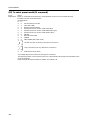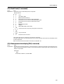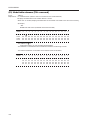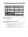
1
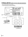
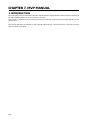
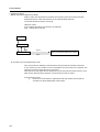
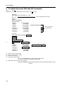
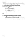
MVP MANUAL
CHAPTER
7. MVP MANUAL
1. INTRODUCTION
The multi video processor (hereafter referred to as MVP below) is equipped with a serial interface conforming to
RS-232C standards which can be connected to computers.
This manual is required when connecting the MVP to the external computer and controlling adjustments and
performance.
This manual describes the methods of using the RS-232C interface, command protocols, and basic functions
and commands of the MVP.
140
MVP MANUAL
2. CONNECTION WITH MVP EXTERNAL COMPUTER
• Refer to Chapter 4.(P.105) “External Control by MPJ RS-232C” for how to adjust the MPJ.
¶ Use a RS-232C straight cable.
¶ Refer to the following diagram for connections.
¶ MVP RS-232C Settings
Baud rate
Bit number
Parity
Stop bit
:
:
:
:
:
2400, 4800 , 9600, 19200
7, 8
NON , ODD, EVEN
1 ,2
Setting at shipment
This setting can be changed using the DIP switches on the panel.
Refer to “Chapter 2.(P.19) MVP panel 7 Baud rate switch”.
<MVP RS-232C Pin Layout>
Signal name
1
14
13
FG
Tx
Rx
RTS
CTS
DSR
SG
Frame Ground
Trandmitted Data
Received Data
Requenst to Send
Clear to Send
Data Set Ready
Signal Ground
25
Connection with External Computer
<External Computer Side>
<Video Processor Side>
Straight
RS-232C IN
FG
1
1
FG
TxD 2
2
RxD
RxD 3
3
TxD
RTS 4
4
CTSl
CTS 5
5
RTSl *
DSR 6
6
DSRl
SG
7
7
SG
* Pins 4, 5 and 6 are short-circuited inside.
Pins not shown in the diagram are NC.
141
MVP MANUAL
3. INSTRUCTIONS FOR USING A COMPUTER AS A TERMINAL
<When the IBM-PC/AT is used>
¶ Use commercially available communications software.
¶ Use PC-DOS internal commands (TYPE, COPY, etc.)
Pay attention to use because only one-way transmission of data is possible in this case.
<With the PC-9800 series>
¶ Use commercially available communications software (CCT 98, etc.)
¶ Use the MS-DOS commands (TYPE, COPY, etc.)
Pay attention to use because only one-way transmission of data is possible in this case.
<Example of a program GW-BASIC>
100
110
120
130
140
150
160
170
180
190
OPEN ”COM1:9600, N, 7, 1” AS#1
RCV
ON COM1 GOSUB
COM1 ON
LOOP
LOOP
A$=INKEY$:IF A$=”” THEN
PRINT#1,A$;
LOOP
GOTO
RCV
IF LOC(1)<>0 THEN PRINT INPUT$(LOC(1),#1);
RETURN
<Communication mode settings in use of CCT98>
Set the CCT98 communication mode before executing the MVP commands.
After starting up CCT98,
F6 ...................... Enter the parameter setting mode.
Set the following items as follows.
Communication speed
2400 4800 9600 19200
Character length
7 bits 8 bits
Stop bit
1 bit 2 bits
Parity bit
None ODD EVEN
Character code
NEC
Transmission carriage return code CR
Reception carriage return code
CR
SI/SO control
None
X control
None
................................ MVP setting at shipment
Selectable
Fixed
* Problems may occur in signal transfer at 2400 bps when adjusting the optional variable scan board.
* Refer to the CCT98 manual for how to use the CCT98.
142
MVP MANUAL
4. OPERATING MODES
1. Normal mode
: This mode is set when the power and reset switches are pressed.
This makes the panel switch effective and sets the performance mode according to the
switch settings.
2. Operation mode : Mode which enables MVP from the external computer.
This mode is set when the ! command is transmitted after connecting the computer.
The normal mode can be set according to the command used.
!
Power ON
Normal mode
Operation mode
@8 (OPTION input 4-screen enlarged)
@9 (V IN input 4-screen enlarged)
3. Manual mode
: Mode in which the panel switches are effective.
Both the 1 and 2 modes are set to this mode normally.
4. Remote mode
: Mode in which the panel switch functions can be controlled from the computer in the
optional mode.
During this time, the panel switch state will be ignored.
Take note that switch settings and operations will not correspond in this mode.
This mode can be changed to the manual mode according to the commands.
For details, refer to the RMT and MNL commands.
143
MVP MANUAL
5. Adjustment Mode
¶ NTSC Input Board Adjustment Mode:
Mode in which the adjustment commands of the NTSC input board can be executed.
(Adjustment items of the output board can be executed when desired)
To end the adjustment mode, input AJN.
Operation mode
AJYC Enables the NTSC input board to be adjusted.
AJN Adjustment mode end
Power ON
Normal mode
!
@h
AJYC
NTSC input board adjustment mode
Operation mode
AJN
¶ Variable scan board adjustment mode:
This is the mode for enabling communications with the optional variable scan board.
In this mode only the variable scan board adjustment commands are accepted. The
switches on the front panel will also not function.
Note that the image output will be disturbed in particular when the Mode switch is operated. Set the switch properly after the communications mode is exited.
In the operation mode:
:A
Mode for communications (adjustment) with the variable scan board set.
:
Variable scan board adjustment mode exited.
144
MVP MANUAL
5. MVP VIDEO OUTPUT MODES
¶ The video output formats set by the mode switches are as shown in the following table.
(At shipment, the mode switch value is set to “8”.)
Mode switch No. Bus format
0
1
2
3
4
5
6
7
8
9
A
B
C
D
E
F
Output format
VBS, Y/C
NTSC
RGB
Sync signal frequency
Standard speed
Dropout reduction function
OFF
Double speed
Reserved
VBS, Y/C
NTSC
RGB
Standard speed
ON
Double speed
Reserved
¶ Bus format
¶ Output format
: NTSC .......................... NTSC digital signal transmission method.
: VBS (VIDEO signal), Can be switched between Y/C and RGB.
However, VBS and Y/C can only be used for the standard speeds.
¶ Sync signal frequency
: Standard speed ......... Horizontal 15.734 kHz, vertical 59.94 Hz interlace
: Double speed ............. Horizontal speed 31.469 kHz, vertical 59.94 Hz non-interlace
¶ Dropout reduction function: Function for alleviating dropout due to the scanning line structure particular to
multi vision systems
NOTE:
With the RMD-V2550U, only standard speed input is possible. Double speed signals can not be displayed.
145
MVP MANUAL
6. ADJUSTMENT FUNCTIONS
MVP enables the input and output boards to be adjusted and set by connecting the external computer. The
following are items which can be set.
(1) MVP settings
• For adjusting the picture frame (output image position) (Coarse adjustments:Refer to &P, &Q command,
fine adjustment:&G command), and correcting the joinings of the magnified screen.
(2) NTSC input board setting
• Bright adjustment (Refer to BRT command)
• Color correction (Refer to COL command)
• Tint adjustment (Refer to TNT command)
(3) Variable scan board settings
• For adjusting the screen display position (Refer to HPS, VPS, HWN, VWN, HWD, VWD commands)
Sets the variable scan board position to the correct position on the screen.
• Tracking adjustment (Refer to TRK command)
For correcting lateral vibration of displayed characters, shaking, and tracking noises.
• Full dot number adjustment (Refer to HFD command)
For correcting vertical bit lines of displayed characters and pictures with high resolution.
(Normally, the full dot number need not be changed.)
• Blanking frame bright adjustment (Refer to BKL command)
For setting the luminance level of the blanking frame for decreasing burning when there are blanking
frames in the surrounding area.
Take note that of the effective display range of the PC screen and blanking frame position are not accurate,
this adjustment will on the contrary have negative effects.
• Vertical filter conversion rate setting (Refer to LCV command)
For correcting the aspect ratio, etc.
However, the vertical resolution deteriorates according to the compensation rate.
• RGB gain adjustment (Refer to RGN, GGN, and BGN commands)
• R–Y, B–Y clamp level adjustment (Refer to RLV, BLV commands)
• Contrast adjustment (Refer to CNT command)
• Bright adjustment (Refer to BRT command)
146
MVP MANUAL
7. PICTURE FRAME ADJUSTMENT PROCEDURES
Adjust the MVP picture frame as follows.
(1) Connect the RS-232C cable to the MVP panel.
(Refer to (P.141) “Connection with MVP external computer”.)
(2) Initialize the picture frame data in RAM.
ex. &L0
(Refer to &L command.)
(3) Set to the magnified screen to be adjusted.
ex. M11C22
)
(@9
(Refer to the M command, @ command.)
(4) Perform coarse adjustment of the picture frame.
ex. &P21
++––
(Refer to the &P command.)
(5) Perform fine adjustment of the picture frame.
ex. &G0
LLRU
(Refer to the &G command.)
(6) Repeat steps (4) and (5) for every position on the screen.
(7) Save the adjustment data in the EEPROM.
ex. &W1 (Refer to the &W command.)
1. Command reference
(1) To shift to the operation mode [! command]
Input:
!
Explanation: By executing this command when the power is on, various commands can be executed.
(2) To set different screens for adjusting convergence [DFFC command]
Input:
DFFC
Explanation: • By executing this command, the V IN input image will be displayed on a single 1x1 display.
• Use the crosshatch, etc. for V IN input images.
• For convergence adjustment, refer to the MPJ’s adjustment items.
(Returning to 4-screen enlarged display)
• The V IN input image is set to 4-screen enlarged display by @9
page 148.)
. (For the @ commands, refer to
147
MVP MANUAL
(3) To set the system back to 4-screen magnification [@ command]
Input:
@h
(h=8 or 9)
Explanation: • For setting the system back to 4-screen magnification after convergence adjustment, etc.
• Used also when the normal 4-screen magnification output cannot be obtained due to incorrect
operations, etc.
@8
................... (Sets 4-screen magnification of the OPTION input)
................... (Sets the 4-screen magnification of the V IN input)
@9
NOTE) An input board must be added in order to display the image of the OPTION input. (Option)
2. Adjusting the picture frame
(1) To perform fine adjustment of the picture frame [&G command]
Input:
&Gh
Explanation: • Performs fine adjustments of the picture frame of the screen specified by the parameter h value.
h : VOUT output No. (0 to 3)
The parameter h value is as shown in the following figure when viewed from the front.
0
1
2
3
• Picture frame fine adjustment command. If the picture frame moves considerable, first perform
coarse adjustments of the picture frame using the &P2 command and &Q2 command. (Refer to
page 149.)
When &Gh is executed, the following is shown on the computer display.
&G3
(Bottom right screen of 4-screen)
+F –F: The horizontal and vertical adjustment values are output at the +F and –F positions.
: Input the following commands after
.
0 : To reset the picture frame fine adjustment data
L : To move the screen to the left
R : To move the screen to the right
U : To move the screen up
D : To move the screen down
: Ends the adjustment mode
• Note: For details of the picture frame adjustment procedure, refer to “Picture Frame Adjustment Procedure”.
• Note: To end the adjustment, be sure to input
.
is not input, commands input thereafter may not be executed.
If
• Note: If the power is cut in this state, the new screen start position data will not be saved. To save the data,
execute &W1
. (Refer to the &W command.)
148
MVP MANUAL
(2) To perform coarse adjustments of the picture frame [&P2, &Q2 commands]
Input:
Explanation:
&P2d2h1h2h3, &Q2d2h1h2h3
&P2 command: Horizontal direction
&Q2 command: Vertical direction
d2 : Screen position (1 to 2)
h1h2h3 : crew start position data (&P2:000 to 1C5, &Q2:000 to 20A)
Although the data is an absolute value, the relative value with the current data can also be specified.
• Input:
&P2d2
&Q2d2
d2
+
–
&P2d2
***
+–+–
+
+
, &P2d2
, &Q2d2
–
–
: Screen position (1 to 2)
: Left direction (horizontal), and up direction (vertical) looking at the screen.
: Right direction (horizontal), and down direction (vertical) looking at the screen.
: Adjustment mode end
: Input the current value at ***
&P2d2
***
RES
: RES is the initial value
&P2d2
***
100
: Input the value after checking the current value
• The screen start position is the position of the screen actually displayed in respect to the magnified image.
Position displayed on the screen
Magnified image
• This command is used for the coarse adjustment of the picture frame when the adjustment range
is exceeded with the &G command.
• The data shift amount is greater than the &G command.
• Execute &W0
to initialize. (Refer to &W command.)
• Note: For details of the picture frame adjustment procedure, refer to ''Picture Frame Adjustment Procedure".
.
• Note: To end the adjustment, be sure to input
is not input, commands input thereafter may not be executed.
If
• Note: If the power is cut in this state, the new screen start position data will not be saved. To save the data,
execute &W1
. (Refer to the &W command.)
149
MVP MANUAL
(3) To store the picture frame data [&W command]
Input :
&W0, &W1
Explanation : &W0 : Sets the saved values to the settings at shipment.
(Load data using the &L command.)
&W1 : Saves the value adjusted.
• The parameters saved by the &W command are as follows.
• Picture frame data (Data changed by the &G command.)
• Screen start position data (Data changed by the &P2 command and &Q2 command.)
• Note : When this command is executed, the setting will be saved even if the power is turned off.
Therefore, all precious settings will be erased.
(4) To load the picture frame data [&L command]
Input :
&L0, &L1
Explanation : &L0 : Loads the picture frame data set at shipment on the RAM.
&L1 : Loads the picture frame data saved at the end on the RAM. (Data when power is turned on)
• The parameters loaded by the &L command are as follows.
• Picture frame data (Data changed by the &G command.)
• Screen start position data (Data changed by the &P2 command and &Q2 command.)
• Use this command to reference the adjustment data temporarily.
150
MVP MANUAL
3. To switch the image input [IFF command]
Input:
IFFa
Explanation: Switches between the V IN input 4-screen enlarged display and the OPTION input 4-screen enlarged display.
a: Image input (A or C)
A: OPTION input image display
C: V IN input image display
Example)
Parsonal computer
OPTION input
MVP
LD
V IN input
IFFC
IFFA
1 2 3 45 6 7 8 9
A B C DE F G H I
RGB
Personal
computer
LD
* Refer to the @ command (page 148) if the normal 4-screen magnification cannnot be set due to incorrect
operations.
* An input board must be added in order to display the image of the OPTION input. (Option)
151
MVP MANUAL
4. To indicate the current MVP state [SYS command]
Input:
SYS
Explanation: The current MVP state is shown when SYS
is input.
(Example)
RMD-V3000 Series PROGRAM Ver. 1.00A
ID
0
This is displayed continuously.
MODE 8
DEMO 8
GEN LOCK INTERNAL
MANUAL MODE
L2 INPUT
:
V.SCAN BOARD
L3 INPUT
:
NO BOARD
L4 INPUT
:
NTSC BOARD
STANDARD MODE VBS
L5 INPUT
:
NO BOARD
This is displayed
L6 OUTPUT
:
4 OUT BOARD
countinuously.
L7 OUTPUT
:
NO BOARD
L8 OUTPUT
:
NO BOARD
L9 OUTPUT
:
NO BOARD
(Contents)
RMD-V3000 Series PROGRAM Ver. 1.00A *1
ID
0 *2
MODE 8 *3
DEMO 8 *4
GEN LOCK INTERNAL *5
MANUAL MODE *6
L2 INPUT
:
V.SCAN BOARD *8
L3 INPUT
:
NO BOARD
*9
L4 INPUT
:
NTSC BOARD
STANDARD MODE
L5 INPUT
:
NO BOARD
L6 OUTPUT
:
4 OUT BOARD *11
L7 OUTPUT
:
NO BOARD
L8 OUTPUT
:
NO BOARD
L9 OUTPUT
:
NO BOARD
*7
*1
*2
*3
*4
:
:
:
:
*10
VBS
Program version information
ID No. selection switch setting
Mode switch setting
Input video switch setting
(8 : 4-screen magnification by optional RGB input board)
(9 : 4-screen magnification by NTSC input board)
*5 : GEN LOCK internal and external displays
GEN LOCK INTERNAL: Internal synchronization (normally fixed at internal synchronization)
152
MVP MANUAL
*6 : Display of remote and manual states
REMOTE MODE
: Remote state
MANUAL MODE
: Manual state
*7 : Slot number
*8 : Type of input board
NTSC BOARD
: NTSC input board
V.SCAN BOARD
: Variable scan board (option)
NO BOARD
: No input board is incorporated
*9 : NTSC input board state
STANDARD MODE
: When standard NTSC signal is input
NO STANDARD MODE : When non-standard NTSC signal is input
*10: Display of VBS/ Y/C select switch state
VBS : Composite video signal input (Indicates V FIL.ON for the V.SCAN BOARD)
Y/C
: Y/C separation signal input (Indicates V FIL.OFF for the V.SCAN BOARD)
*11: Type of output board
4 OUT BOARD
: 4 output board
NO BOARD
: No output board is incorporated
5. To perform NTSC input board picture quality adjustment
(1) To set the adjustment mode [AJYC command]
(2) To exit the adjustment mode [AJN command]
Input:
Explanation:
AJYC
, AJN
AJYC command : Sets the NTSC input board to the adjustment mode.
AJN command : Exists the adjustment mode.
• When adjusting the NTSC input board, the adjustment command will be ignored if AJYC is not
executed.
* To set the optional variable scan board to the adjustment mode:
: Use the :A command. (Refer to page 156 and on.)
153
MVP MANUAL
(3) Bright compensation [BRT command]
Input:
Explanation:
BRTd
Corrects the brightness of the NTSC input board.
d
: Compensation value 0 to F
*
: Displays the current value and moves to the sub command mode
BRTd
• To execute this command, it is necessary to set the adjustment mode by AJYC. (Refer to the
AJYC command.)
• The changed value will be memorized the last.
(Example) BRT3
Sets the bright level to 3.
*Sub command mode of BRT command
.
The sub command mode is set by BRT
(Example) BRT3
*
* indicates the current value.
Input + and – at the
cursor position.
(CR) to end.
Always input
(4) Color compensation [COL command]
Input:
Explanation:
COLd1d2d3
Corrects the color of the NTSC input board.
: Compensation value 0 to 255
d1d2d3
: Help display
COL?
: Displays the current value and moves to the sub command mode
COL
• To execute this command, it is necessary to set the adjustment mode by AJYC. (Refer to the
AJYC command.)
• If data input is skipped, the sub command input mode is set after the data is displayed.
COL sub command mode
The COL sub command mode is set by COL
.
(Example) COL
***
*** indicates the current value.
Input the following sub command at the
cursor position.
Always input
(CR) to end.
0 to 255
: Ends the sub command mode after a number has been input.
+, – : Increases/decreases the data by one step.
UP1 to 9, 0 : Increases the current data by 1 to 10 steps.
DW1 to 9, 0 : Decreases the current data by 1 to 10 steps.
RES : Defaults the adjustment value (factory setting).
: Ends the sub command input mode.
• The changed value will be memorized the last.
(Example) COL
UP0
: Increases the color compensation value by 10 steps.
154
MVP MANUAL
(5) Tint adjustment [TNT command]
Input :
TNTd1d2d3
Explanation: Corrects the tint of the NTSC input board.
: Compensation value 0 to 255
d1d2d3
TNT?
: Help display
: Displays the current value and moves to the sub command mode
TNT
• To execute this command, it is necessary to set the adjustment mode by AJYC. (Refer to the
AJYC command.)
• If data input is skipped, the sub command input mode is set after the data is displayed.
The sub command mode is the same as with the COL command.
• The changed value is memorized the last.
(Example) TNT
Indicates the current tint value.
128
6. Controls the panel switch function
(1) To set the manual mode [MNL command]
(2) To set the remote mode [RMT command]
Input :
MNL
, RMT
Explanation : • Manual mode
• Remote mode
: Makes the following switch functions effective.
1 Variable scan board filter on/off switch
2 VBS/ Y/C select switch
3 MODE switch (The RESET button is required.)
The manual mode is set at POWER ON (or RESET button).
: Mode in which the above switching setting are selected via the RS-232C line.
In this case, the above switch states are ignored.
The settings which can be switched by the remote mode are as follows.
• Optional RGB board FILTER ON/OFF switching
Refer to the DSY and DSN commands (RMD-V3020)
• V IN (Composite video/YC separate) switching
Refer to the CIC and YIC commands.
• V OUT output format (MODE) switching
Refer to NT, NTR, NTD commands.
(3) To select composite video input [CIC command]
Input :
CIC
Explanation : • Select the composite video input of NTSC input board.
• This command is executed in the remote mode.
It is ignored in the manual mode. (Refer to the RMT command.)
(4) To select YC separation input [YIC command]
Input :
YIC
Explanation : • Selects the Y/C separation input of the NTSC input board.
• This command is executed in the remote mode.
It is ignored in the manual mode. (Refer to the RMT command.)
155
MVP MANUAL
(5) To set the output to the NTSC mode [NT command]
(6) To set the output to standard RGB mode [NTR command]
(7) To set the output to the double-speed RGB mode [NTD command]
Input :
NT , NTR , NTD
Explanation : • NT : Sets the NTSC input mode.
H : 15.734 kHz
V : 59.94 Hz
Composite video, Y/C output
• NTR : Sets the standard speed RGB mode.
H : 15.734 kHz
V : 59.94 Hz
• NTD : Sets the double-speed RGB mode.
H : 31.469 kHz
V : 59.94 Hz
• This command is executed in the remote mode.
It is ignored in the manual mode. (Refer to the RMT command.)
(NOTE)
With the RMD-V2550U, only standard speed input is possible.
(8) Optional variable scan board adjustment mode settings [:A command]
Input :
:A
Explanation: • Used when adjusting the optional variable scan board (RMD-V3020).
• To exit the adjustment mode, omit the parameters and input : .
• For details on adjustments, refer to “VS Board Command Reference” on the following pages.
156
MVP MANUAL
8. DEMO PATTERN SETTINGS AND CAUTIONS
The MVP does not have an RMD-V3216 type DEMO switch, but 2x2 enlarged screen automatic display is possible by reading the input selector switch (OPTION/V IN) when the power is turned on and executing the command corresponding to that setting.
Because of this, upon shipment from the factory command examples for displaying the MVP 2x2 enlarged
screens have been written into the demonstration switch No. 8 and No. 9 areas, which were user program areas
on the RMD-V3216.
Switch No. 8 contains the command example for displaying 2x2 enlarged screens for the OPTION input picture
(A input).
Switch No. 9 contains the command example for displaying 2x2 enlarged screens for the V IN input picture (C
input).
2x2 enlarged screens may not be displayed if the contents of demo No. 8 and demo No. 9 are replaced. If this
happens, reset the factory defaults.
The commands written into the set upon shipment from the factory and the procedure for writing the commands are described below.
!
&NO011
&NO121
&NO212
&NO322
[8
W3
M11A22
]
[9
W3
M11C12
]
: Start the command interpreter and input the following commands.
: Matrix screen number setting ........ Set VOUT1 matrix coordinate to 11.
: Matrix screen number setting ........ Set VOUT2 matrix coordinate to 21.
: Matrix screen number setting ........ Set VOUT3 matrix coordinate to 12.
: Matrix screen number setting ........ Set VOUT4 matrix coordinate to 22.
: Write in the command example for 2x2 enlargement of the A input to demonstration switch No.
8.
: Write in the command example for 2x2 enlargement of the C input to demonstration switch No. 9.
End.
The RM-V1000NU’s internal MVP assembly (AWU1014-) uses slots A and B, but this set uses slots A and C.
Note that because of this the M command setting is different.
157
MVP MANUAL
9. INSTALLING AND REMOVING BOARDS
<Removal procedure>
For your safety
¶ Be sure to turn the power off before installing
and removing boards.
<Installation procedure>
1 Remove the front panel.
2 Remove the screws fastening the board to the
removed. (Fig. C)
3 Lift the ejectors indicated with white arrows. (Fig.
B)
4 Gently draw out the board along the rails.
5 Set the front panel back in place.
1 Remove the screws from the front panel, then
open the front panel. (Fig. A)
2 Insert the board gently along the rails.
Refer to the board layout for the positions for inserting the boards.
12345
3 Press the12345part of the white plastic part
strongly with a finger and insert the board fully
to the back. (Fig. C)
* The board may not go fully to the back if pressed
on the metal part.
4 Fasten with the flanged screws (3x6). (Fig. C)
5 Set the front panel back in place.
(Fig. B)
(Fig. A)
Screw (3x6)x6
(Fig. C)
158
MVP MANUAL
<Board layout>
Lane exclusively for control boards =
L1 + Insertion lane
Lane exclusively for option boards =
L2 + Insertion lane
Lane exclusively for input boards =
L3 + Insertion lane
Lane exclusively for output boards =
L4 + Insertion lane
Power unit
Only service personnel should touch
this.
<Relationship between board insertion lanes and rear panel connectors>
Board insertion lane Rear panel connector (refer to the diagram of the rear panel on page 18)
L2 Ô OPTION
L3 Ô V IN
L4 Ô V OUT
The board insertion lanes and rear panel connectors are paired as shown above.
159
MVP MANUAL
10. RMD-V3020 COMMAND REFERENCE
(1) Outline of the RMD-V3020
• Introduction
The RMD-V3020 is an input board (hereafter referred to as VS board) which supports variable scanning for
inputting images of computer (hereafter referred to as PC) to the MVP.
Horizontal frequency
: 24 kHz to 35 kHz
Vertical frequency
: 55 Hz to 72 Hz
Dot clock
: Up to 35 MHz
Signal
: Non-interlace signal
(The HDTV, 15 kHz RGB signal will not be displayed because it is interlaced.)
• Basic functions
With the VS board, standard PC signal information is preset in the memory. When the PC signal is input to the
MVP, the images are automatically output in the best state through this board after the model has been
discriminated. (For details of the preset models, refer to the M commands of the VS board described later.)
Although non-preset models must also be adjusted using general data, images can be output temporarily
and these models are compatible with recent PCs, accelerator boards with various resolutions. (Refer to
Mode 99 described later.)
Automatic detection cannot be performed but a user-presetable area for 31 models is provided. This enables
the data of unknown models to be registered and used in the same way as preset model data.
• Precautions in use
In some cases, problems may occur when communication is carried out with the MVP at 2400 bps in the
adjustment of the VS board, etc.
• VS board adjustment mode
In the communication state with the MVP, the VS board adjustment mode can be set by inputting :A.
160
MVP MANUAL
(2) VS board command rules
0.
Symbols
aaa
ddd
xxx
hh
1.
: Command consisting of 3 alphabet letters
: Basic commands : Decimals between 0 to 255 consisting of 1 to 3 digits. Can start with 0.
Exceptional commands : Depends on each command.
: Special data. UP0 to UP9, UPF, DW0 to DW9, DWF, RES.
: 2-character hexadecimals between 00 and FF.
Basic commands
• Executed commands
aaa : Executes and ends.
ARS, DSN, DSX, DSY, FZN, FZY
• Displayed commands
aaa : Displays and ends.
FRQ, TBL, STS, VER
• Numerical commands
aaa
: Displays and sets sub command state.
aaaddd : Performs immediate settings, displays, and sets sub command state.
aaaxxx : Performs special settings, displays, and sets sub command state.
TRK, RGN, GGN, BGN, CNT, RLV, BLV, BRT, BKL, HPS, VPS, HWN, VWN, HWD, VWD, HFD
• Sub commands
ddd : Performs immediate settings, and displays.
xxx : Performs special settings, and displays.
+
: Performs UP1 special settings and updates display.
–
: Performs DW1 special settings and updates display.
: Ends sub command state.
Other commands can be input even if the sub command state has not been ended. In this time, the sub
command input mode will be canceled automatically.
• Errors
When aaa contains an error, the “COMMAND ERROR” state is set and the current value is displayed. When
ddd contains characters other than 0 to 9, or is outside the 0 to 255 range, the “DATA ERROR” state is set and
the current value is displayed. When xxx contains an error, the “DATA ERROR” state is set and the current
value is displayed.
When an error occurs in the sub command state, the “SUB COMMAND ERROR” state is set and the current
value is displayed.
161
MVP MANUAL
2.
Exceptional commands
• Model data commands
TBL
: Displays the current model data table.
TBLhh
: Displays the hh model data table.
M
: Displays the current model number.
Mhh
: Sets the hh model number.
Fhh
: Sets the hh model number data to the initial value.
When the hh model data does not exist, “**NO DATA**” is displayed. When hh contains characters other
than 0 to 9, a to f, and A to F, “DATA ERROR” is set.
• Frequency commands
HFQ
: Displays the current model determination H frequency.
HFQRES
: Sets the current model determination H frequency to the initial value, and displays it.
HFQddd.ddd : Changes and displays the current model determination H frequency. (Take note of the
decimal point.)
VFQ
: Displays the current model determination V frequency.
VFQRES
: Sets the current model determination V frequency to the initial value, and displays it.
VFQddd.ddd : Changes and displays the current model determination V frequency. (Take note of the
decimal point.)
In the case of frequency commands, both the integer and decimal of ddd.ddd must be decimal 3 digit numbers. Numbers between 000.000 to 999.999 can be input.
When d is a character other than 09, when the number of digits is wrong, or the decimal point is at the wrong
place, “DATA ERROR” is set, and the current model determination frequency is displayed.
• Line conversion command
LCV
: Displays the current model line conversion rate.
LCVRES
: Sets the current model line conversion rate to the initial value, and displays it.
LCVdddd : Changes and displays the current model line conversion rate
In the case of line conversion commands, dddd must be a decimal 4 digit number, and the first two digits
must be 0015 and the last two must be above 00 and below the first two digits. If d is a character other than 09,
or the number of digits is wrong, “DATA ERROR” is set, and the current line number conversion rate is
displayed.
Both 0000 and 0101 are not convertible.
• Line number command
VLN
: Displays the current model determination line number.
VLNRES
: Initializes and displays the current model determination line number.
VLNddd
: Changes and displays the current model determination line number.
In the case of the line number command, ddd must be a decimal 3 digit number. Numbers between 000 and
999 can be input.
When d is a character other than 09, or when the number of digits is wrong, ‘’DATA ERROR” is set, and the
current line number is displayed.
162
MVP MANUAL
(3) Tracking adjustment [TRK command]
Input :
TRKd1d2d3
Explanation: • d1d2d3 : Compensation data 0 to 254
• Eliminates lateral vibration of displayed characters, shaking, and noises.
TRK adjustment
• A vertical line pattern in which the black and white lines change every dot as shown below is the
ideal for adjustments.
(4) Contrast adjustment [CNT command]
Input :
CNTd1d2d3
Explanation: • d1d2d3 : Compensation data 0 to 254
• Use this command to adjust the contrast.
• Use this command to adjust so that the contrast of the images produced by the MVP matches the
contrast of the actual images of the computer.
• Tracking may deviate in some cases when CNT adjustment is performed after TRK adjustment.
After adjusting CNT, adjust TRK.
(5) R, G, B gain adjustment [RGN, GGN, BGN commands]
Input :
RGNd1d2d3, GGNd1d2d3, BGNd1d2d3
Explanation: • d1d2d3 : Compensation data 0 to 254
• GGN : Green gain adjustment
RGN : Red gain adjustment
BGN : Blue gain adjustment
• Use this command to adjust so that the white balance of the images produced by the MVP
matches the white balance of the actual images of the computer.
• Tracking may deviate in some cases when gain adjustment is performed after TRK adjustment.
After adjusting gain, adjust TRK.
(6) Brightness adjustment [BRT command]
Input :
BRTd1d2d3
Explanation : • d1d2d3 : Compensation data 0 to 254
• Use this command to adjust the brightness.
• Use this command to adjust so that the brightness of the images produced by the MVP matches
the brightness of the actual images of the computer.
• Tracking may deviate in some cases when brightness adjustment is performed after TRK adjustment. After adjusting brightness, adjust TRK.
163
MVP MANUAL
(7) B, R clamp adjustment [BLV, RLV commands]
Input :
BLVd1d2d3, RLVd1d2d3
Explanation : • d1d2d3 : Compensation data 0 to 254
• BLV : Adjusts the B clamp level.
RLV : Adjusts the R clamp level.
• Use this command to adjust so that the white balance of the low light side of the images produced by the MVP matches that of the actual images of the computer.
• Tracking may deviate in some cases when clamp level adjustment is performed after TRK adjustment. After adjusting the clamp level, adjust TRK.
(8) Blanking window level adjustment [BLK command]
Input :
BLKd1d2d3
Explanation : • d1d2d3 : Compensation data 0 to 254
• Adjusts the bright level of the blanking window.
• Use to adjust the VS board picture frame and prevent burning.
• Adjust the blanking window position and width using HWN, HWD, VWN, and VWD.
(9) Horizontal, vertical direction screen display position adjustment
[HPS, VPS commands]
Input :
HPSd1d2d3, VPSd1d2d3
Explanation : • d1d2d3 : Compensation data 0 to 254
• HPS : Moves the screen horizontally.
VPS : Moves the screen vertically.
However, the blanking window does not move and only the screen inside the window moves.
The moving range of the screen is not limited to the blanking window.
Monitor frame
Blanking window (Does not move)
A
A
PC image
Figure: Example of HPS Command Execution
(Note)
HPS, HWN, and HWD are commands to change reading and writing timings of the image memory,
and are mutually correlated. For this reason, Each of these three commands has a limited value
without varying the 0 to 255 range.
VPS, VWN, and VWD are also the same.
When the above command become the limited values, the image blinks three times.
164
MVP MANUAL
(10) Horizontal, vertical blanking window position adjustment
[HWN, VWN commands]
Input :
HWNd1d2d3, VWNd1d2d3
Explanation : • d1d2d3 :Compensation data 0 to 254
• HWN :Adjusts the H blanking window position.
VWN :Adjusts the V blanking window position.
However, the picture inside the blanking window also moves.
HWN, VWN adjustments
Figure: Example of HWN, VWN Command Adjustment
(Note)
HPS, HWN, and HWD are commands to change reading and writing timings of the image memory,
and are mutually correlated. For this reason, Each of these three commands has a limited value
without varying the 0 to 255 range.
VPS, VWN, and VWD are also the same.
When the above command become the limited values, the image blinks three times.
(11) Horizontal, vertical blanking window width adjustment
[HWD, VWD commands]
Input :
HWDd1d2d3, VWDd1d2d3
Explanation : • d1d2d3 : Compensation data 0 to 254
• The pedestal of the video signal is masked by blanking which can adjust the bright level.
• HWD : Adjusts the H blanking window width.
VWD : Adjusts the V blanking window width.
PC image
AAA
AAA
HWD adjustment
Figure: Example of HWD Execution
(Note)
HPS, HWN, and HWD are commands to change reading and writing timings of the image memory,
and are mutually correlated. For this reason, Each of these three commands has a limited value
without varying the 0 to 255 range.
VPS, VWN, and VWD are also the same.
When the above command become the limited values, the image blinks three times.
165
MVP MANUAL
(12) Full dot number compensation [HFD command]
Input :
HFDddd
Explanation : • d1d2d3:Compensation data 0 to 254
• Corrects the preset sampling clock.
• Vertical bit lines can be erased by executing the HFD command.
• The HFD and HPS data are correlated and have limited values.
Bit lines
Figure: Bit Lines which can be Erased by HFD Execution
(13) Freeze frame Y:ON N:OFF [FZY, FZN commands]
Input :
FZY, FZN
Explanation : • Continuously outputs the image the moment the FZY is executed. This is canceled by FZN.
• Whether the state is FZY or FZN can be determined by executing the STS command.
• Do not perform position adjustments in the FZY state.
(14) Vertical filter ON/OFF [DSY, DSN, DSX commands]
Input :
DSY, DSN, DSX
Explanation : • Converts the vertical line number so that the computer images can be displayed fully on the
monitor.
• The conversion rate preset by the LCV command can be changed. (Refer to LCV command.)
• Whether the state is DSY or DSN can be determined by executing the STS command.
DSY
480 vertical lines
400 vertical lines
DSN
Figure: Example of DSY and DSN Executions (MAC 6-5 Conversion Example)
• The DSX is a command which makes the V.FIL switch on the rear of the MVP effective.
166
MVP MANUAL
(15) Vertical compression filter conversion rate input [LCV command]
Input :
LCVd1d2d3d4
Explanation : • d1d2=00 to 15 (Add 0 before all numbers below 9) Vertical direction rate before conversion
• d3d4=00 to 15 (Add 0 before all numbers below 9) Vertical direction rate after conversion
Due to the use of a compression filter, the condition=is d1d2 > d3d4.
Both LCV0000 and LCV0101 are not convertible.
• Directly changes the vertical filter conversion rate of the data table of the model using the VS
board currently.
• When the conversion rate is changed for DSY, the image compressed by the new conversion rate
will be output.
(Example)
: LCV0605
Set 6–>5 conversion
(16) Program ROM version display [VER command]
Input :
VER
Explanation : • Indicates the version of the program ROM mounted in the current VS board.
(Example)
: VER
PROGRAM VERSION=BXY1004-X VX.XX 199X.XX.XX
(17) To indicate the current function setting [STS command]
Input :
STS
Explanation : • Displays the model data No., selected state (auto or forced), vertical filter ON, OFF, and freeze
ON, OFF selected by the VS board currently.
(Example)
: STS
STATUS=DSY, FZN
MODEL NO.=09 AUTO
: STS
STATUS=DSY, FZN
MODEL NO.=03 FIXED
Autolocks to PC9801 with the left display, indicates vertical
filter ON, freeze OFF.
Forcible locks the Macintosh with the left display, indicates
vertical filter ON, freeze OFF.
167
MVP MANUAL
(18) To select preset model [M command]
Input :
Mh1h2
Explanation : • Refer to “VS Board Model Selection” described later for the VS board model selection.
• Forcible locks the model data preset.
Model data No.
h1 h2
0
0
Discriminates the model.
0
1
VGA (640 x 480)
0
2
IBM-PC (EGA emulation)
0
3
Macintosh 13-inch monitor mode (Standard)
0
4
Macintosh 13-inch monitor mode (RasterOps type)
0
5
Macintosh 13-inch monitor mode (Power Mac)
0
6
FM-R50
0
7
IBM Think Pad 230C
0
8
X68000
0
9
NEC PC9801 (640 x 400 mode)
1
0
Unused area (Do not specify using the M command.)
2
7
2
8
User preset area (Use only with the M command.)
5
8
9
9
Models other than above.
This model data can be locked only using the M command.
The data range which can be preset by the user is 28 to 58. 28 to 58 contains the VGA data (same
as 01) at shipment.
Refer to Mode 99 mentioned later for details of model No. 99.
168
MVP MANUAL
(19) Model fresh [F command]
Input :
Fh1h2
Explanation : • Sets back to the model data preset at shipment.
Model data No.
h1 h2
0
0
Auto
0
1
VGA (640 x 480)
0
2
IBM-PC (EGA emulation)
0
3
Macintosh 13-inch monitor mode (Standard)
0
4
Macintosh 13-inch monitor mode (RasterOps type)
0
5
Macintosh 13-inch monitor mode (Power Mac)
0
6
FM-R50
0
7
IBM Think Pad 230C
0
8
X68000
0
9
NEC PC9801 (640 x 400 mode)
1
0
Unused area (Do not specify using the M command.)
2
7
2
8
User preset area
5
8
9
9
Models other than above.
This model data can be locked only using the M command.
The data range which can be preset by the user is 28 to 58. 28 to 58 contains the VGA data (same
as 01) at shipment.
Refer to Mode 99 mentioned later for details of model No. 99.
(20) Measurement data display [FRQ command]
Input :
FRQ
Explanation : • Displays the horizontal frequency, vertical frequency, and full line number of the personal computer connected to the MVP currently. Use as reference when inputting the data of models whose
details are unknown.
(Example)
: FRQ
fH=24 kHz, fV=56.4 Hz, 1V=440 LINE.
169
MVP MANUAL
(21) Model table reference [TBL command]
Input :
TBLh1h2
Explanation : hh model data No. (Refer to the M command for the model data No.)
• Displays the data table of the model data h1h2 model.
When h1h2 is omitted, displays the data table of the model connected to the VS board currently.
(Example)
: TBL
MODEL NO.=09 AUTO (Indicated autolocked to PC98.)
ADDR
0
1
2
3
4
5
6
7
8
9
A
B
C
D
E
F
C140
C150
C160
C170
09
FF
FF
FF
05
FF
FF
48
64
FF
FF
30
32
FF
FF
08
04
FF
FF
48
40
FF
FF
01
00
FF
FF
45
30
FF
FF
06
04
FF
FF
40
00
FF
FF
38
11
FF
FF
20
FF
FF
FF
FF
FF
FF
FF
FF
FF
FF
FF
FF
FF
FF
FF
FF
FF
FF
FF
The address of is:
C140 (Left number) +1 (Top number)=C141 address.
This address is considered as the hexadecimal address conforming to C140.
The relative addresses on the table are as follows. (Not model data.)
ADDR
170
0
1
2
3
4
5
6
7
8
9
A
B
C
D
E
F
00
10
20
30
01
11
21
31
02
12
22
32
03
13
23
33
04
14
24
34
05
15
25
35
06
16
26
36
07
17
27
37
08
18
28
38
09
19
29
39
0A
1A
2A
3A
0B
1B
2B
3B
0C
1C
2C
3C
0D
1D
2D
3D
0E
1E
2E
3E
0F
1F
2F
3F
MVP MANUAL
The relative address and data are as follows.
However, relative addresses 20 to 3F are the system reservation range.
Relative
ADDR
00
01
02
03
04
05
06
07
08
09
0A
0B
0C
0D
0E
0F
Data Contents
Model data No.
Horizontal frequency
NNN.NNN kHz
(BCD 6 digits) Note 1
Total horizontal dots
(BCD 4 digits)
Horizontal effective start position
(BCD 4 digits)
Horizontal effective dot number
(BCD 4 digits)
Clamp head
Clamp period
Gain upper limit
Clamp upper limit
Note 2
Sync method
Sync polarity
Note 3
Relative
ADDR
10
11
12
13
14
15
16
17
18
19
1A
1B
1C
1D
1E
1F
Data Contents
Reservation
Vertical frequency
NNN.NNN kHz
(BCD 6 digits)
Total vertical line number
(BCD 4 digits)
Vertical effective start position
(BCD 4 digits)
Vertical effective line number
(BCD 4 digits)
Line conversion rate Note 4
Reservation
PLL gain
Reservation
Note 1 : For example, taking the PC98 table on the previous page as an example, as the relative addresses 01,
02, and 03 contain data 02, 48, and 30, the PC98 horizontal frequency setting value is 24.83 kHz.
Note 2 : FF when the method is not limited.
Note 3 : FF when the polarity is not limited.
Note 4 : If the relative address data is:
65 : Indicates 6-5 conversion
A7 : Indicates 10-7 conversion.
(22) Horizontal frequency input [HFQ command]
Input :
HFQd1d2d3.d4d5d6
Explanation : • Directly changes the horizontal frequency of the model data table used for the VS board currently.
• Input the frequency using 6-digit decimal numbers. When data input is omitted, the horizontal
frequency on the current model data table is displayed.
• Refer to “Using Methods of HFQ, VFQ, VLN” described later on the using methods.
(Example)
HFQ035.123
Input 35.123 kHz
(Take note to input 0 at first.)
Although numbers outside the horizontal frequency specification range (24.0 kHz to 35.0 kHz)
range of this board can be input, they cannot be used as preset data.
171
MVP MANUAL
(23) Vertical frequency input [VFQ command]
Input :
VFQd1d2d3.d4d5d6
Explanation : • Directly changes the horizontal frequency of the model data table used for the VS board currently.
• Input the frequency using 6-digit decimal numbers. When data input is omitted, the vertical frequency on the current model data table is displayed.
Although numbers outside the vertical specification range (55.0 kHz to 72.0 kHz) range of this
board can be input, they cannot be used as preset data.
• Refer to “Using Methods of HFQ, VFQ, VLN” described later on the using methods.
(Example)
VFQ060.123
Input 60.123 kHz
(Take note to input 0 at first.)
(24) Vertical full-line input [VLN command]
Input :
VLNd1d2d3
Explanation : • 3-digit decimal numbers between 000 to 999 can be input for ddd.
• Directly changes the vertical full line number of the model data table used for the VS board
currently.
• Refer to “Using Methods of HFQ, VFQ, VLN” described later on the using methods.
(25) All reset [ARS command]
Input :
ARS
Explanation : • Sets back the adjustment data, etc. memorized by the VS board to the shipment values.
• As all the data registered by the user are set back to the initial values, use this command carefully.
172
MVP MANUAL
11. MODE 99
The VS board contains preset data for autolocking 9 computer main models at shipment.
However, looking at the recent PC market is taken into consideration, it is not possible to incorporate preset data
in all models due to the diversification of manufacturers, models, and graphic mode, etc.
For this reason, the variable scan board has been forcibly locked to the mode called model data 99 for personal
computers without preset data in order to output the personal computer screen to the monitor.
Consequently, it can deal with many of the 24 kHz to 35 kHz personal computers (the upper limit for the dot clock
is 35 MHz).
However, this model No. 99 has several restrictions in order to deal with numerous personal computers.
• When the HFD command to change the sampling clock exceeds 35 MHz, the image may become blur.
Use 99 without moving HFD as much as possible.
• At the point the personal computer locked to model No. 99, dusts may appear at the top and bottom as shown
in the figure.
Dusts appearing at the top and bottom.
In such cases, use the VWM, VPS and VWD commands
to mask the dirt.
• The RGB board is the upper limit at which the dot clock 35 MHz ensures performance.
The following is a simple calculation method of the dot clock.
Dot clock (Hz)=Effective dot number x Horizontal frequency (Hz) x 1.35
• Use Mode 99 to output images temporarily. When used, it is recommended that the user preset area (No. 28
to 58) be changed and used after checking the frequency, etc. using FRQ command.
• The G on Sync model is not locked in the Mode 99.
173
MVP MANUAL
12. VS BOARD MODEL SELECTION
PC signal input
Preset PC?
(01 to 09)
YES
NO
Locked in Mode 99?
NO
YES
Output in Mode 99
The model may be outside
the application range.
Auto locked
Check frequency,
line number using
FRQ command
Frame, color
adjustment
Lock preset model data
using M command.
When using the Mode
99 data as it is.
Description
With the VS board, first the input PC frequency and full line number are measured. Next, if there are preset
models which have three matching measuring data, it is determined that these models are connected and they
are set into the autolock state.
In the autolock state, 01 AUTO is displayed by the STS command.
If there exists no preset model data corresponding to the measuring data, all models are autolocked to Mode 99.
(Refer to “MODE 99”.)
Take note that there are DOS/V personal computers which have 640 effective dot number and 480 effective line
number but a different full line number (526 or 524) from the standard VGA 525. In this case, their models are
autolocked to Mode 99.
As the frequency is close to the VGA, when the VS board is forcible locked to the VGA by M01 and data is output,
the image frame, etc. will be optimum. In this way, the M command is used when using the preset data as
substitute data.
13. USING METHODS OF HFQ, VFQ, VLN
There is a need to autolock unpreset models without using the Mode 99 accoridng to the state in which the VS
board is used.
The procedure is as follows.
1.
2.
3.
4.
5.
6.
Input a PC without the preset data.
Autolock to 99.
Check the frequency and full line number using the FRQ command.
Forcible lock using the M command to the model with a similar frequency.
Input the checked data using HFQ, VFQ, and VLN.
Execute M00 and check that it has been auto locked.
Unpreset models can also be autolocked using the above procedure. To set back the original state, use the F
command.
174
MVP MANUAL
14. SELECTING THE SYNC SIGNAL
When adjusting the VS board, care must be taken regarding the relation of the priority order of the sync
signal.
Order of selecting the sync signal
The priority order for selecting the sync signal of the VS board is
Separate sync > composite sync > Green on sync.
However, if the sync signal of a certain method is selected once according to the connection and power ON/
OFF order, even if sync signals with a higher priority order than that sync signal are connected later, sync
selection will not be switched.
In this case, however, the priority order will be selected again when the power of the converter is turned on
again.
Frame for Sync Signal
The horizontal frame values are saved according to the sync signal currently selected.
For this reason, the horizontal frame may deviate according to the type of sync signal even with the same
computer.
(Example)
When models with both the composite sync and green on sync are connected (Frequently with Macintosh)
1 Connect cables G, B, R, and CS in this order with the power of the input personal computer and converter on.
The green on sync is selected.
2 After connecting the cable with the power of the input personal computer on, turn on the power of the
converter.
The composite sync will be selected.
When frame adjustment is carried out in the 1 state, 2 state is set when the power is turned on the next
time, meaning that the frame deviates.
It is necessary to set state 2 at all times so that the same sync signal is selected during both adjustments and
use.
175