1
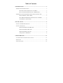
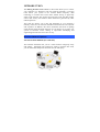
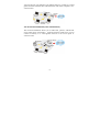
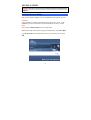
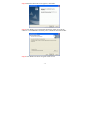
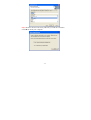
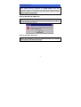
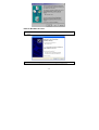
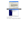
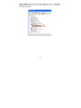
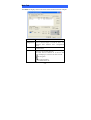
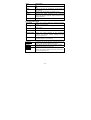
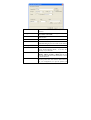
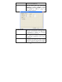
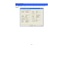
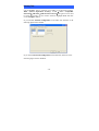
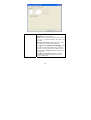
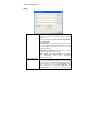
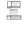
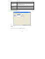
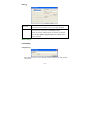
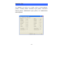
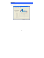
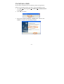
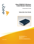
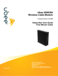
Model # AWLH3025
User’s Manual
Ver. 1A
REGULATORY STATEMENTS
FCC Certification
The United States Federal Communication Commission (FCC) and the
Canadian Department of Communications have established certain rules
governing the use of electronic equipment.
Part15, Class B
This device complies with Part 15 of FCC rules. Operation is subject to the
following two conditions:
1) This device may not cause harmful interface, and
2) This device must accept any interface received, including interface that may
cause undesired operation. This equipment has been tested and found to
comply with the limits for a Class B digital device, pursuant to Part 15 of the
FCC Rules. These limits are designed to provide reasonable protection
against harmful interference in a residential installation. This equipment
generates, uses and can radiate radio frequency energy, and if not installed
and used in accordance with the instructions, may cause harmful interference
to radio communications. However, there is no guarantee that interference
will not occur in a particular installation. If this equipment does cause
harmful interference to radio or television reception, which can be
determined by turning off and on, the user is encouraged to try to correct the
interference by one or more of the following measures:
◗Reorient or relocate the receiving antenna.
◗Increase the distance between the equipment and receiver.
◗ Connect the equipment into an outlet on a circuit different from that to
which the receiver is connected.
CAUTION:
1) To comply with FCC RF exposure compliance requirements, a separation
distance of at least 20 cm must be maintained between the antenna of this
device and all persons.
2)
This transmitter must not be co-located or operating in conjunction with
any other antenna or transmitter.
Table of Contents
INTRODUCTION...................................................................................... 1
WIRELESS NETWORK OPTIONS ................................................................. 1
The Peer-to-Peer Network (a.k.a. Ad-Hoc).................................. 1
The Access Point Network (a.k.a. Infrastructure) ........................ 2
LED INDICATORS FOR WIRELESS NETWORK ADAPTER CARD ................. 3
Power Indicator: (Green LED) ..................................................... 3
This LED will illuminate when the driver is installed.................. 3
Act Indicator: (Green LED) ......................................................... 3
INSTALLATION ....................................................................................... 4
INSTALL THE DRIVER & UTILITY .............................................................. 4
INSTALL THE DEVICE................................................................................. 7
Note for Windows 98 & ME users:.............................................. 7
Note for Windows 2000 users:..................................................... 7
Note for Windows XP users:........................................................ 8
Verify Device Installation ............................................................ 9
CONFIGURATION................................................................................. 11
ACCESSING THE CONFIGURATION UTILITY ............................................. 11
MAIN TAB ............................................................................................... 12
ADVANCED TAB ..................................................................................... 17
PRIVACY TAB ......................................................................................... 18
WEP Configuration.................................................................... 20
CCX Configuration .................................................................... 22
WPA settings.............................................................................. 23
STATISTICS TAB ...................................................................................... 25
ABOUT TAB ............................................................................................ 26
UN-INSTALLATION .............................................................................. 27
APPENDIX ............................................................................................... 29
INTRODUCTION
The 802.11g Wireless LAN Card is a device that allows you to connect
your computer to a Wireless Local Area Network (WLAN). A wireless
LAN allows your system to use wireless Radio Frequency (RF)
technology to transmit and receive data without having to physically
attach to the network. The wireless protocols that come with this product
ensure data security and isolation from interference generated by other
radio frequencies.
This card also allows you to take full advantage of your computer’s
mobility with access to real-time information and online services anytime
and anywhere. In addition, this device eliminates the hassle of pulling
cable through walls and under furniture. It even allows you to place your
system in locations where cabling is impossible. Modifying and
augmenting networks has never been so easy.
Wireless Network Options
The Peer-to-Peer Network (a.k.a. Ad-Hoc)
This network installation lets you set a small wireless workgroup easily
and quickly. Equipped with wireless PC Cards or wireless PCI cards,
you can share files and printers between each PC and laptop.
-1-
You can also use one computer as an Internet Server to connect to a wired
global network and share files and information with other computers via a
wireless LAN.
The Access Point Network (a.k.a. Infrastructure)
The network installation allows you to share files, printers, and Internet
access much more conveniently. With the Wireless LAN Card, you can
connect wirelessly to a wired global network via an access point or
wireless router.
-2-
LED Indicators For Wireless Network Adapter Card
Power Indicator: (Green LED)
This LED will illuminate when the driver is installed.
Act Indicator: (Green LED)
This LED flickers when
transmitting/receiving data.
the
Wireless
-3-
Network
Adapter
is
INSTALLATION
Caution: Be sure to power off your computer before inserting the PCI
adapter.
Install the Driver & Utility
Step 1 Insert the PCI adapter into an available PCI slot and turn on your
computer.
Step 2 Windows will detect the adapter and request for a driver. Click
Cancel to quit the wizard and insert the Installation CD into your CD
drive.
Step 3 Select Install Utility from the setup menu.
Note: If the setup menu does not appear automatically, click Start, Run,
type D:\autorun.exe (where D is the letter of your CD drive) and click
OK.
-4-
Step 4 When the Welcome screen appears, click Next .
Step 5 Click Next to accept the default destination folder to install the
software or click Browse to manually select a different destination folder.
Step 6 Click Next at the Select Program Folder screen.
-5-
Step 7 Remove the Driver & Utility CD from your CD drive and then
click OK to restart your computer.
-6-
Install the device
Note: Make sure the procedures in “Install Utility” have been
performed. In most cases, Windows will automatically install the driver
after the computer is restarted, if the Found New Hardware Wizard
appears, follow the steps below.
Note for Windows 98 & ME users:
Before installing the device, make sure you have your Windows 98 or
ME CD at hand. You may be asked to insert the Windows 98 or ME CD
in order to install specific files.
Note for Windows 2000 users:
During the installation, when the “Digital Signature Not Found”
screen appears, click “Yes” to continue.
-7-
Note for Windows XP users:
1. Select Install the software automatically (Recommended) and click
Next.
3. Click Continue Anyway at the Windows Logo testing screen.
-8-
4. Click Finish to complete the installation.
Verify Device Installation
To verify that the driver has been properly installed in your computer, go
to Start Æ Settings Æ Control Panel Æ System (Æ Hardware) Æ
-9-
Device Manager. Expand the Network adapters item. If the 802.11g
Wireless PCI Card is listed, it means that your device is properly
installed and enabled.
- 10 -
CONFIGURATION
After successfully installing the driver and utility, a Utility Icon will
appear on the desktop.
If the Utility Icon doesn’t appear automatically, go to Start Æ (All)
Programs Æ Airlink101 Æ Wireless LAN Utility.
Accessing the Configuration Utility
The Configuration Utility is accessed by double-clicking on the Wireless
LAN Utility Icon on the Desktop.
All settings are categorized into 5 Tabs:
Main Tab
Advanced Tab
Privacy Tab
Statistics Tab
About Tab
- 11 -
Main Tab
The Main tab displays the current status of the Wireless Network Adapter.
Item
Description
External
Uncheck the box to use this utility to configure the
Configuration wireless network adapter. Or check the box to use
Windows XP’s Wireless Zero Configuration
Utility.
Status
Displays the information about the status of the
communication.
SSID
The SSID is the Network ID shared among all
devices in your wireless network.
The name must be identical for all devices and
points attempting to connect to the same network.
No encryption
Encryption enabled
For TI-Based WLAN
- 12 -
Item
Description
For TI-Based WLAN with encryption
Mode
Ch
Signal
BBS ID
Displays the type of connection: Access Point or
Peer-to-Peer.
Displays the channel that is currently in use.
Displays the signal strength of the connection
between the Wireless Network Adapter and the Access
Point it connects to.
Displays the MAC address of the target device.
Current Configuration
Pref. SSID
Shows the current SSID the wireless network
adapter is connected to.
BSS Type
Shows the current connection type: Access Point or
Peer to Peer.
Channel
Shows the current channel.
Tx Rate
Shows the current transfer rate.
Signal Quality
Shows the signal strength of the connection
between the wireless network adapter and the
device it connects to.
The MAC address of the device that the wireless
network adapter is connected to.
BSSID
Connect
Modify
Rescan
Highlight one of the devices from the device list
and press the Connect button to access it.
There will be two tabs for you to modify, see the
detailed information on next page.
Searches all available networks. Clicking on this
button, the wireless adapter will start to rescan and
list all available devices.
- 13 -
Preferred SSID
BSS Type
Tx Rate
Channel
Power Mode
Type in the SSID name of the device you want to
connect to.
You can select the connection type: Peer-to-Peer,
Access Point or Auto Mode.
You can select the data rate or set to auto mode from the
pull-down menu.
Select the channel you want to use.
No Power Save:the adapter will be in full active mode.
Max Power Save:the power save mode will be enabled.
4x Config
Packet Burst Enable
Mode
Profile
Select to disable or enable the TI-Based 4x function.
Enable this function(if the device you connect
supports Packet Bursting Mode) to increase the
efficiency of your network.
Select from IEEE 802.11b(B-Only), 802.11b
+(B-Plus) , 802.11g (G-Only) or B&G Mode (If you
choose this option the device will automatically convert
the suitable standard ).
Enter the profile name and click the Save button to
save your configuration, To open the profiles you
- 14 -
saved, select the profile from the pull-down menu
and then click the Load button.
Tx Power Level
Fragment Threshold
RTS Threshold
Preamble
Select the transmit power level: Low Power,
Medium-Low
Power,
Medium
Power,
Medium-High Power, High Power. The power
level function is used to extend the
communication distance.
You can fragment the MSDU or MMPDU into
smaller sizes to increasing the reliability of frame
transmission. (The maximum value of 4096 means
no fragmentation is needed). The throughput
performance will decrease however.
This value should remain at its default setting of
4096. Should you encounter inconsistent data
flow, only minor modification of this value is
recommended.
A preamble is a signal used in wireless environment
to synchronize the transmission timing, including
Synchronization and Start frame delimiter. (Note: If
you want to change the Preamble type to Long or
- 15 -
Short, please check the settings of your access point
or wireless router.
Retry limits
You can set the number of retries if no
acknowledgement appears from the receiving
station.
- 16 -
Advanced Tab
The Advanced tab displays the current status of the Wireless Network
Adapter.
- 17 -
Privacy Tab
Use the Privacy Tab to configure your WEP, CCX and WPA settings.
WEP (Wired Equivalent Privacy), CCX ( Cisco Compatible
Extension)and WPA(WiFi Protected Access)encryption can be used
to ensure the security of your wireless network. Highlight WEP and click
on the Configure button.
If you uncheck External Configuration in the Main tab, functions in the
following figure will be enabled.
If you checked External Configuration in the Main tab, functions in the
following figure will be disabled.
- 18 -
Privacy Mode
Configure WEP, CCX, 802.1x and WPA settings.
NONE:No security defined.
WEP is a data security mechanism based on a 40
Bit (a.k.a. 64 Bit)/128 Bit/256 Bit shared key
algorithm.
WPA(WiFi Protected Access)is more secure
than WEP, and should be used if possible.
CCX(Cisco Compatible Extension)provides
user-based, centralized authentication, as well as
per-user wired equivalent privacy (WEP) session
keys. Press the Configure button to change CCX
configuration.
The 802.1x Configuration window is used to
configure WEP, CCX and WPA security with
802.1x authentication.
- 19 -
WEP Configuration
None:
Authentication
Encryption 1-4
The authentication type defines ID verification and
access privileges of roaming wireless network
cards.
You may choose from Open System, Shared Key,
or Auto Switch.
Open System: If your access point/wireless router
is using "Open System" authentication, then the
wireless adapter will need to be set to the same
authentication type.
Shared Key: Shared Key is when both the sender
and the recipient share a secret key.
Auto Switch: Select Auto Switch for the adapter
to
automatically
select
the
appropriate
authentication mode.
WEP (Wired Equivalent Privacy) encryption can
be used to ensure the security of your wireless
network. Select one Key and Key Size then enter
the appropriate key value in the Encryption field.
Note: You must use the same Key #, Key Size, and
Encryption Key on both the host and destination
- 20 -
Key size
devices in order to establish a connection.
KEY1 ~ KEY 4:You can specify up to 4 different
keys, but only one can be used at a time.
Encryption:Enter the key value in this field.
A key of 10 hexadecimal characters (0-9, A-F) is
required if a 40-bit (a.k.a. 64-bit) Key Size is
selected.
A key of 26 hexadecimal characters (0-9, A-F) is
required if a 128-bit Key Size is selected.
A key of 58 hexadecimal characters (0-9, A-F) is
required if a 256-bit Key Size is selected.
Select from 40-bit (a.k.a. 64-bit), 128-bit or
256-bit.
802.1x Configuration
The 802.1x Configuration window is used to configure WEP, CCX and
WPA security with 802.1x authentication.
Protocol
This panel enables you to select an authentication
protocol.
Password
This panel is available when EAP-TLS is not selected
(either MSCHAP V2 over PEAP is selected with WEP
or LEAP is selected for CCX). This panel enables you
to enter a login name and password or request that the
driver prompt for them when you connect to a
- 21 -
network.
Personal
Certificate
This panel is available when EAP-TLS protocol is
selected and enables you to select a certificate for
authenticating the station.
User Name
Type in the user name assigned to the certificate.
Browse
Select a certificate by clicking Browse.
Server Certificate You can select to enable or disable server certificate.
CCX Configuration
None:
Refer to the previous section for WEP Configuration.
- 22 -
802.1x:
EAP-TLS
EAP-TLS is a mutual authentication method, which means
that both the client and the server prove their identities.
LEAP
Network administers have been taking advantage of the simplified
user and security administration that LEAP provides.
Before the security authentication is started, you should
enter the user name and password or the authentication
process will fail.
WPA settings
Preshared Key
Passphrase:
Enter the key that you are sharing with the network for the WLAN
connection.
- 23 -
802.1x:
Refer to the previous section for 802.1x Configuration.
- 24 -
Statistics Tab
The Statistics Tab displays any available statistics including Receive
packets, Transmit packets, Association reject packets, Association
timeout packets, Authentication reject packets, and Authentication
timeout packets.
- 25 -
About Tab
Click on the About tab to view basic version information about the OS Version,
Utility Version, Driver Version, Firmware Version and EEPROM Version.
- 26 -
UN-INSTALLATION
If you need to uninstall the driver and utility, follow the steps below.
(When you uninstall the utility, the driver will be uninstalled as well.)
1. Go to Start Æ (All) Programs Æ Airlink101Æ Uninstall Wireless
LAN Utility.
2. Click OK to continue.
3. Select Yes, I want to restart my computer now, and then click
Finish to complete the uninstalled procedure.
- 27 -
- 28 -
Appendix
Technical Support
E-mail: [email protected]
Toll Free: 1-888-746-3238
Web Site: www.airlink101.com
- 29 -