1
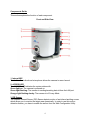
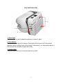
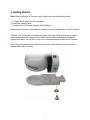
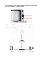
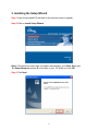
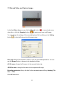
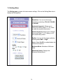
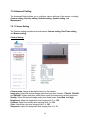
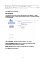
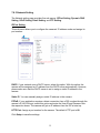
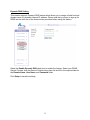
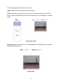
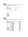
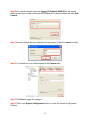
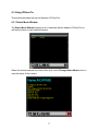
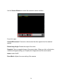
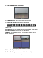
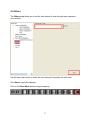
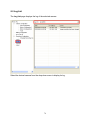
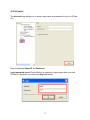
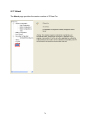
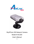
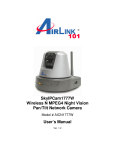
SkyIPCam 650
Model # AICAP650
User’s Manual
Ver. 1.0
Table of Contents
1. Introduction................................................................................................................................. 3
2. Getting Started ............................................................................................................................ 7
3. Installing the Setup Wizard......................................................................................................... 9
4. Using the Setup Wizard ............................................................................................................ 11
5. Viewing Images ........................................................................................................................ 14
6. Enabling and Installing ActiveX............................................................................................... 16
7. Web Configuration Utility ........................................................................................................ 19
7.1 Main Menu.......................................................................................................................... 20
7.2 Preset Menu ........................................................................................................................ 22
7.3 Record Video and Capture Image....................................................................................... 23
7.4 Setting Menu....................................................................................................................... 24
7.5 Multiview Mode.................................................................................................................. 25
7.6 Advanced Setting ................................................................................................................ 26
7.6.1 Camera Setting............................................................................................................. 26
7.6.2 Security Setting............................................................................................................ 29
7.6.3 Network Setting ........................................................................................................... 32
7.6.4 System Setting ............................................................................................................. 37
7.6.5 Maintenance................................................................................................................. 40
8. Viewing Videos from External Network .................................................................................. 45
9. IPView Pro................................................................................................................................ 48
9.1 Installing IPView Pro.......................................................................................................... 48
9.2 Starting IPView Pro ............................................................................................................ 50
9.2.1 Adding Camera using the Search Method ................................................................... 51
9.2.2 Adding Camera using the Input IP Method ................................................................. 55
9.3 Using IPView Pro ............................................................................................................... 57
9.3.1 Status Mode Window................................................................................................... 57
9.3.2 View Window and View Mode Buttons...................................................................... 59
9.3.3 Control Panel ............................................................................................................... 60
9.4 System Configuration ......................................................................................................... 62
9.4.1 Web Configuration....................................................................................................... 63
9.4.2 Motion Configuration-1 ............................................................................................... 64
9.4.3 Motion Configuration-2 ............................................................................................... 66
9.4.4 Tools ............................................................................................................................ 67
9.5 Mail Configuration.............................................................................................................. 68
9.6 Proxy Server........................................................................................................................ 69
9.7 Recording Configuration .................................................................................................... 70
9.7.1 Schedule-Recording Configuration ............................................................................. 71
9.8 Others.................................................................................................................................. 73
9.9 Log List............................................................................................................................... 74
9.10 Account ............................................................................................................................. 75
9.11 About................................................................................................................................. 76
Frequently Asked Questions ......................................................................................................... 77
Specification ................................................................................................................................. 79
Technical Support ......................................................................................................................... 81
2
1. Introduction
Congratulations on your purchase of this SkyIPCam 650. The IP Camera allows you to
view images and live videos from internal and external networks. With a built-in CPU
and Web Configuration Utility, the IP Camera is a standalone network device that
delivers high quality videos at a low cost of ownership. The built-in Web Configuration
Utility allows any computer that’s connected to the network to remotely manage the IP
Camera. Combined with the bundled Setup Wizard and IPView Pro software, managing
and viewing multiple IP Cameras is simple and efficient.
Instructions for installing and configuring this product can be found in this manual.
Before you install and use this product, please read this manual carefully for proper
operation of the product.
Package Contents
Before you begin the installation, please check the items of your package:
•
•
•
•
•
•
SkyIPCam 650
Camera Stand
RJ-45 Ethernet Cable
AC Power Adapter
Quick Installation Guide
Installation CD
If any item contained is damaged or missing, please contact your local dealer
immediately. Also, keep the box and packaging materials in case you need to ship the
unit in the future.
System Requirement
Please review the following system requirement.
•
•
•
•
•
OS: Windows® 98SE/ME/2000/XP and other OS supporting TCP/IP
CPU: 650MHz or above (2.4 GHz recommended when monitoring multiple
cameras simultaneously)
Memory Size: 256MB
Resolution: 1024x768 or above
Web Browser: Internet Explorer 5.0 or above
3
Components Guide
This section explains the function of each component.
Front and Side View
1. Internal MIC
The built-in Omni-directional microphone allows the camera to record sound.
2. ACCESS LED
The ACCESS LED indicates the system status with:
Green light on: The camera is powered on.
Green light flashing: The camera is sending/receiving data to/from the LAN port.
Orange light flashing slowly: The camera is in Privacy Mode.
3. PIR Sensor
The Passive Infrared Sensor (PIR) Sensor detects motion of an infrared emitting source
which allows you to monitor the target area dynamically. In order to use this motion
detection feature, you have to enable the sensor from the Web Configuration Utility.
4
4. Camera Lens
To adjust the focus of the lens, turn the lens slowly in either clockwise or counterclockwise direction until the image is in focus. DO NOT overturn the lens in either
direction.
5. Flash LED
The Flash LED allows you to capture video images even in dark environments. You can
turn on the flash light from the Web Configuration Utility.
6. USB Port
The USB port allows you to expand the storage medium by connecting a USB storage
device via the USB port. Please refer to Section 7.6.2 Security Setting for information
about storing image files to the USB device via motion sensor triggers and/or via
scheduled settings. You can click on the Log Display sub-menu to monitor any activity
for the USB port. The Camera will stop the storage and activate the buzzer when the
USB storage device has less than 5% of remaining free space.
7. STATUS LED
The STATUS LED indicates the configuration status with:
Green light flashing: The camera is powered on and functions in normal mode.
Orange-Red light flashing: Indicates the camera cannot access DHCP within the
network.
8. Privacy Mode Button
Press this button to enter into Privacy Mode. The camera stops monitoring in this mode.
Also, you can safely remove the USB storage device from the USB port by pressing and
holding this button for 5 seconds until the camera activates the buzzer.
9. LAN Port
This RJ-45 connector is used to connect the 10Base-T Ethernet or 100Base-TX Fast
Ethernet network cable (which should be Category 5 twisted-pair cable). The port
supports the NWay protocol, allowing the camera to automatically detect or negotiate
the transmission speed of the network.
10. DC Power Connector
The DC power input is labeled DC 5V with a single jack socket to supply power to the
camera. Power will be generated when the power supply is connected to a wall outlet.
11. Camera Stand
The camera stand allows you to place the camera on a flat surface instead of hanging
on the wall or installing on a tripod.
5
Rear and Bottom View
1. Screw Hole
The screw hole is used to attach the camera to a stand or tripod.
2. Reset Button
Press the button to reboot the camera. Press and hold the button for 5 seconds will
reset the camera’ settings to the factory default. Alternatively, you can perform reboot or
factory reset from the Web Configuration Utility.
3. Hanging Hole
These two holes allow you to hang the camera on a wall.
6
2. Getting Started
Note: Before using the IP Camera, you’ll need to perform the following tasks:
1. Connect the IP Camera to your network.
2. Install the Setup Wizard.
3. Configure the IP Camera using the Setup Wizard.
Please follow the steps in this Manual carefully to ensure proper setup of the IP Camera.
Caution: The IP Camera is designed for indoor use only. Direct exposure to sunlight
may cause permanent damage to the CMOS sensor. When operating in extremely
bright environment, an iris lens or sun visor is recommended to protect the IP Camera.
Step 1 Align the camera stand with the bottom part of the camera. Then, secure the
camera stand with the screw.
7
Step 2 Connect one end of the network cable to the IP Camera and connect the other
end to one of the LAN ports of the router or switch.
Step 3 Power on the IP Camera by connecting one end of the supplied power adapter
to the power jack of the Camera and connecting the other end to an electrical outlet.
Step 4 Verify that the LED lights on the Camera are lit. If not, verify that all the
connections are secure and try again.
8
3. Installing the Setup Wizard
Step 1 Insert the provided CD and wait for the autorun screen to appear.
Step 2 Click on Install Setup Wizard.
Note: If the autorun screen does not appear automatically, go to Start, Run, type
D:\ Setup\Setup.exe (where D is the letter of your CD drive) and click OK.
Step 3 Click Next.
9
Step 4 Click Yes to accept the License Agreement.
Step 5 Click Next to accept the default Destination Folder.
Step 6 Click Finish to complete the installation.
10
4. Using the Setup Wizard
Step 1 Go to Start > (All) Programs > AirLink101 IP Camera Setup Wizard >
AirLink101 IP Camera Setup Wizard.
Step 2 Select the IP Camera you want to configure from the list and click on the Wizard
button.
11
Step 3 If the Camera’s default IP address is on a different subnet, the following
message will appear. Click Yes to continue. If you do not receive this message, skip to
Step 6.
Step 4 Enter admin for both the Admin ID and Password and click OK.
Step 5 The Wizard will automatically generate an IP address for the camera, if this
address is not in use by any other device in your local network, click OK. Otherwise,
enter an available IP address (ex. 192.168.x.240) and click OK.
12
Step 6 Enter admin for both the Admin ID and Password field and click Next.
Optionally, you can change the password by checking on the Change box and entering
the new password.
Step 7 If you need to change the Camera’s IP address because another network device
is already using the same address, you can assign a new address here and click Next.
Step 8 Verify that all the fields are correct and click Restart to save the settings and
reboot the camera.
13
5. Viewing Images
Note: The following steps describe how to view images from within the same local area
network as the IP Camera. To view images from an external network such as the
Internet, please refer to Section 8 of this manual for further instructions.
Step 1 At the Setup Wizard, select the desired camera from the list and click on the
Web Config button.
Step 2 Enter the password for the camera (Default is admin) and click OK.
14
Step 3 The welcome page appears. If you did not change the default password, you will
be prompted to do so before accessing the camera.
Step 4 The Main menu along with the live video appears on screen. The IP camera is
ready for use now.
Note: ActiveX must be installed and enabled on your Web Browser (Internet Explorer)
before you can view the live videos. For more information, please refer to the next
section.
15
6. Enabling and Installing ActiveX
If no image appears on the web browser (Internet Explorer), follow the steps below to
enable and install ActiveX
Step 1 Open Internet Explorer and go to Tools > Internet Options.
Step 2 Select the Security tab and click on Custom Level.
16
Step 3 Verify the following settings are selected. Click OK when done:
•
•
•
Automatic prompting for ActiveX controls: Enable
Download signed ActiveX controls: Prompt
Run ActiveX controls and plug-ins: Enable
Step 4 Close Internet Explorer and re-launch the Web Config screen.
17
Step 5 Click on the ActiveX Control prompt.
Step 6 Select Install ActiveX Control.
Step 7 Click on Install to install the ActiveX Control.
Step 8 After the ActiveX Control is installed you should see the live video on Internet
Explorer.
18
7. Web Configuration Utility
The built-in Web Configuration Utility allows you to remotely manage the IP Camera
with the ease and convenience of your Web Browser (Internet Explorer). If you are not
using Internet Explorer, you can use the bundled IPView Pro software to manage the
camera. See Section 8 for detail.
Step 1 Open your Web Browser (Internet Explorer), enter the default IP Address of the
Camera 192.168.1.240 in the Address Bar and press Enter.
Note: If you have changed the IP Address of the Camera as described in Section 5,
enter the Camera’s new IP Address instead of the default.
Step 2 Enter the password for the camera (Default is admin) and click OK.
19
The index page displays the menu bar, information bar, and the live video.
7.1 Main Menu
Digital Zoom In/Out
In the Main menu, click the Digital Zoom Bar to zoom in and out of the displayed image
by 1X, 2X, or 4X.
20
Adjust the Camera Lens Position
You can control the camera lens position by clicking the Up/Down/Left/Right arrow
buttons in the Main menu. Clicking the Home button will move the lens to the original
home position. Additionally, you can click directly in the area of the live video to change
the position of the lens.
Flash LED On/Off
The camera is equipped with a powerful Flash LED that allows you to capture clear
images in a dark environment. In low light environment, click the Flash LED button (
) to
turn on the flash light of the camera.
Buzzer On/Off
You can use the Buzzer button (
) to test the internal buzzer of the camera. The
camera will sound a Bi-Bi, Bi, Alarm, Bi-Bo-Bi-Bo, or Robot according to the selected
sound in Buzzer setting of the Web Configuration Utility.
PIR Sensor On/Off
) turns on/off the camera’s motion detection feature which allows
The Sensor button (
you to monitor the target area dynamically.
Privacy Mode On/Off
Click on the Privacy mode button (
) to enter into privacy mode. This stops the
camera from monitoring until it exits the Privacy mode.
21
7.2 Preset Menu
You can preset up to 8 positions for the camera from the Preset menu. This enables
you to move the camera lens to the desired position quickly.
To set up the position, move the camera lens to the desired position first and select the
number (1~8) from the pull-down list, then click the Register button. To identify the
assigned position easily, you can name the position by entering a descriptive name in
the Register name box.
When you have assigned the position for the camera, simply click the Number button
(1~8) and the camera lens will move to the pre-defined position immediately.
22
7.3 Record Video and Capture Image
In the Live Video Area, you can click the Record button (
video clip, or click the Snapshot button (
) to record and save a
) to capture and save a still image.
You can change the settings of the recorded/captured file by clicking on the Setting
button (
), which will bring up the following window:
Save path: Assign the destination folder to save the recorded/captured file. You can
use the Browse button to browse to the destination folder.
AVI file name: Assign the file name for the recorded video clip.
JPEG file name: Assign the file name for the captured still image.
Recording restriction: Set up the limit for the recorded/captured file by Nothing, File
size, or Time.
Click OK when done.
23
7.4 Setting Menu
The Setting menu contains the basic camera settings. Click on the Setting Menu bar to
display the Setting Menu.
Resolution: You can set the image
resolution by selecting 176x144, 320x240,
or 640x480.
Horizontal degree(s): Allows you to
change the moving range (1°~10°) when
you pan the camera lens position.
Vertical degree(s): Allows you to change
the moving range (1°~10°) when you tilt
the camera lens position.
Quality: You can set the image quality by
selecting Low, Med, or High.
Voice: Select On/Off to enable/disable the
camera’s microphone.
Multiview Mode: Switches to Multiview
Mode.
Advanced Setting: Displays the
Advanced Setting menu.
24
7.5 Multiview Mode
If you have multiple cameras connected to your network, you can monitor the videos of
these cameras simultaneously by switching to Multiview Mode. Click the Multiview
Mode button in the Setting menu to change to the following multiview screen.
To add an additional camera, enter the new camera’s IP address and click Register.
You can select the refresh interval from the Refresh interval drop-down list.
To return to the Home page, click Back.
25
7.6 Advanced Setting
The Advanced Setting allows you to configure various settings of the camera, including
Camera setting, Security setting, Network setting, System setting, and
Maintenance.
7.6.1 Camera Setting
The Camera setting provides three sub-menus: Camera setting, Date/Time setting,
and Buzzer setting.
Camera Setting
Camera name: Assign a descriptive name for the camera.
Image size: Select the desired image resolution from three formats: 176x144, 320x240,
and 640x480. Higher resolution yields better quality but uses more network resources.
Quality: Select the desired image quality from three levels: Low, Med, and High.
Brightness: Adjust the brightness level ranging from 1 to 128.
Contrast: Adjust the contrast level ranging from 1 to 128.
Color: Adjust the color level ranging from 1 to 128.
Sharpness: Adjust the sharpness level ranging from 1 to 12.
26
Frequency: To eliminate flicker image, select the proper frequency according to the
camera’s location. The options include: 50Hz, 60Hz, or Outdoor.
Flip Image: Select Horizontal to display the image in a horizontal mirror mode. Select
Vertical to display the image in a vertical mirror mode.
Click Setup to save the settings.
Date/Time Setting
This sub-menu allows you to setup the date and time for the camera. For system
management purposes, a correct date/time setting is critical for accurate time stamps
on the system logs.
Time Zone setting: Select a time zone according to your location.
Synchronize with NTP Server: Select this option and the date/time will be
synchronized with the NTP server you selected.
Manual setting: Select this option to set up the date and time manually.
Click Setup to save the settings.
27
Buzzer Setting
If you enabled the camera’s buzzer feature, you can setup the buzzer type for the
following action: System start, Motion detected, Scheduled operation, and Buzzer
button pressed.
The available buzzer sound include: Bi-Bi, Bi, Alarm, Bi-Bo-Bi-Bo, and Robot.
Click Setup to save the settings.
28
7.6.2 Security Setting
The Security Setting page provides three sub-menus: Sensor setting, Schedule setting,
and Access time setting.
Sensor Setting
This sub-menu allows you to assign the time period for the camera to take the selected
action(s) when motion is detected.
Sensor setting: Select Enable/Disable to enable/disable the camera’s sensor feature.
When you enable this feature, the Use below operation times check box must be
selected so that the settings in Operation time 1/2 can be applied. Otherwise, the
camera will keep detecting motion.
Operation time 1/2: If the camera’s motion sensor is enabled, these two options allow
you to assign the operational time frame for the sensor. If you want to have the camera
constantly detect motion, leave these two options blank.
Action: Select the camera’s response when motion is detected: Buzzer, Email, FTP,
Flash the light, and Save image to USB disk.
Click Setup to save the settings.
29
Schedule Setting
This sub-menu allows you to assign scheduled time period(s) for the camera to perform
the pre-selected actions.
Schedule setup: Select Enable/Disable to enable/disable the camera’s schedule
feature.
Timer 1/2: If the camera’s schedule feature is enabled, these two options allow you to
assign the specific time frame for the camera’s action(s).
You can setup the interval time (by minutes) for the camera’s action in the Interval box.
For example, if you set up 10 minutes, the camera will act every 10 minutes during the
assigned time period.
Action: Select the camera’s action when it reaches the scheduled time: Buzzer, Email,
FTP, Flash the light, and Save image to USB disk.
Click Setup to save the settings.
30
Access Time Setting
This sub-menu allows you to assign the time period for the users to view the live video.
When this feature is enabled, the users can only access the camera to view the live
video during the specified time period. During other times, the message “Access
restricted. Image can not be viewed” will be displayed on the Live Video Area.
Access time setting: Select Enable/Disable to enable/disable the camera’s access
time feature. If you disable the feature, the users are always allowed to view the video.
Access time 1/2: If the camera’s access time feature is enabled, these two options
allow you to assign the specific time frame when users are allowed to view the video.
Click Setup to save the settings.
31
7.6.3 Network Setting
The Network setting page provides five sub-menus: IP/Port Setting, Dynamic DNS
Setting, UPnP Setting, Email Setting, and FTP Setting.
IP/Port Setting
This sub-menu allows you to configure the camera’s IP address mode and assign its
port number.
DHCP: If your network uses a DHCP server, select this option. With this option, the
camera will be assigned an IP address from the DHCP server automatically. However,
please make sure that the DHCP server is set to assign a static IP address to the
camera.
Static IP: You can manually assign a static IP address to the camera.
PPPoE: If your application requires a direct connection from a DSL modem through the
camera’s RJ-45 LAN port, select this option and enter the User ID and Password into
the respective boxes. The camera will get an IP address from the ISP at start up.
HTTP Port: Assign a port number for the camera. The default HTTP port is 80.
Click Setup to save the settings.
32
Dynamic DNS Setting
This camera supports Dynamic DNS feature which allows you to assign a fixed host and
domain name to a dynamic Internet IP address. Please note that you have to sign up for
DDNS service with one of the listed service providers before using this feature.
Select the Enable Dynamic DNS check box to enable the feature. Select your DDNS
Service Provider from the Service Provider drop-down list and fill in the required data for
the Domain Name, User Name, and Password fields.
Click Setup to save the settings.
33
UPnP Setting
UPnP allows peer-to-peer connectivity between various network devices seamlessly.
Select Enable/Disable in the UPnP setting option to enable/disable this function.
Click Setup to save the settings.
34
Email Setting
This sub-menu allows you to configure the Email setting.
If one of the selected actions in the Security setting is Email, you have to specify the
appropriate Email properties.
SMTP/POP server: Enter the mail server in SMTP server or POP server field
according to your network configuration. POP server will be used when the
Authentication mode is set to POP before SMTP.
User name: Enter the user name to log into the mail server.
Authentication mode: Select the correct authentication mode according to the setting
of the mail server.
Password: Enter the password to log into the mail server.
Sender: Enter the e-mail address of the user who will send the e-mail.
To: Enter the e-mail address of the user who will receive the e-mail.
CC: Enter the e-mail address of the user who will receive a copy the e-mail.
BCC: Enter the e-mail address of the user who will receive a secret copy the e-mail.
Click Setup to save the settings.
35
FTP Setting
This sub-menu allows you to configure the FTP Setting.
If one of the selected actions in the Security setting is FTP, you have to specify the
appropriate FTP properties.
FTP server name: Enter the IP address of the target FTP site.
User name: Enter the user name to log into the FTP server.
Password: Enter the password to log into the FTP server.
Directory: Enter the directory for uploading the images.
Fixed filename: Select this box to enable fixed filename and enter the filename.
Passive mode: Select this box to enable passive mode. The default setting is active
mode.
Click Setup to save the settings.
36
7.6.4 System Setting
The System setting page provides two sub-menus that allow you to manage users of
the camera: Administrator password and User setting.
Administrator Password
This sub-menu allows you to change the administrator’s login password.
Enter the new password twice in the New password and New password (confirm)
field to setup the new password for the administrator.
Click Setup to save the settings.
37
User Setting
This sub-menu allows you to configure user-level access to the camera.
User authentication: When this feature is enabled, you have to enter the username
and password in the login window to access the camera. When the option is disabled,
you can directly access the camera as a Power user without entering the username and
password; however, once you try to access the setup page, you will be asked to enter
the administrator’s username and password.
User add/update: To add or modify a user, complete the required settings in the enter
the User Name, Password, and Password (confirm) fields and select whether the
new user will be a Power or Guest user and click Add Update button. The newly added
user will appear under the User list.
38
The following explains the various user levels:
Admin: Have full control and access to the camera
Power: Allowed to use some basic functions of the camera such as Zoom In/Out,
Buzzer, Flash LED, camera’s lens position, Preset menu, and switching to multiview
mode.
Power User View
Guest: Allowed to view live video, and record/capture the video/image by using the
Record/Snapshot buttons.
Guest View
39
7.6.5 Maintenance
The Maintenance page provides six sub-menus: USB Removal, Reboot, Factory
Reset, Firmware Update, Information, and Log Display.
USB Removal
To remove the connected USB storage device safely, click the USB remove button in
this sub-menu before removing the USB device. Alternatively, you can press and hold
the Privacy Mode button for 5 seconds until the camera activates the buzzer indicating
that you can remove the USB storage device from the USB port safely.
40
Reboot
Click Reboot to restart the camera while retaining all the settings.
Factory Reset
Click Yes to return all the settings to factory default.
41
Backup Setting
You can save the camera’s settings to the local hard drive by using the Backup Setting
feature. Click Backup to save the settings.
Follow the on-screen instructions to save the settings. The default filename is Config.cfg
Restore Setting
You can restore previously saved settings by using the Restore Setting feature. Click
Browse to browse for the saved file (Config.cfg), then click Restore to restore the
saved settings.
42
Firmware Update
This sub-menu allows you to update the Camera to the latest firmware.
You can check our website at www.airlink101.com to see if there is a newer firmware
available for download.
Step 1 Download the new firmware from our web site at www.airlink101.com
Step 2 Unzip the new firmware.
Step 3 Click on the Browse button and locate the new firmware.
Step 4 Click on the Upgrade button to begin the upgrade.
43
Information
This sub-menu provides general information of the camera including the firmware
version, networking configuration, and security settings.
Log Display
This sub-menu provides a list that contains the events and actions of the camera.
44
8. Viewing Videos from External Network
If you want to access the Camera from an external network such as the Internet, please
read the following example carefully and follow the steps.
Before you begin, you’ll need to know your Internet IP Address (WAN IP) assigned by
your Internet Service Provider (ISP) and at least one of your ISP’s DNS IP Address.
You can usually find these information on the Status page of your router’s web
configuration utility. If not, you’ll need to contact your ISP for assistance.
Example:
Network A = Location of the Camera
Camera’s IP Address is 192.168.1.240 with HTTP Port 80 Enabled.
Network A’s router has an Internet IP Address (WAN IP) of 172.16.1.1 assigned by the
Internet Service Provider (ISP). The ISP’s DNS IP Address is 10.0.0.1 and 10.0.0.2
Network B = Location of the remote client trying to access the Camera.
Step 1 From one of the computers in Network A, open the web browser (Internet
Explorer or Netscape), enter the Camera’s IP Address 192.168.1.240 in the Address
Bar and press Enter.
Step 2 Enter the username and password for the camera.
45
Step 3 Go to Setting Menu > Advanced Setting > Network Setting > IP/Port Setting.
Step 5 Enter your ISP’s DNS IP Address at the Primary DNS and Secondary DNS
fields.
46
Step 6 Assign a port number for the camera to use. (Default is 80).
Important: You must assign a port number that’s not in use by any other application on
your network.
Step 7 Click Setup to apply the new settings.
Now the Camera with IP Address of 192.168.1.240 has port 80 Open.
Step 8 From one of the computers in Network A, login to the web configuration utility of
Network A’s router.
Step 9 Navigate to the router’s Virtual Server or Port Forwarding page.
Step 10 Enable Forwarding of port 80 to the Camera’s IP Address (192.168.1.240) and
save the new setting.
Step 11 From one of the computers in Network B, open the web browser (Internet
Explorer), enter the Internet IP Address (WAN IP) of Network A’s router
(http://172.16.1.1) followed by a colon : and the number of the open HTTP Port (80) in
the Address Bar and press Enter.
Ex. http://172.16.1.1:80
The remote client in Network B should be able to see the images from the Camera now.
47
9. IPView Pro
The bundled IPView Pro software features a user-friendly interface that allows you to
manage, view, and configure multiple IP Cameras on your network. If your web browser
doesn’t support ActiveX, you may use this software to view the live video instead.
Follow the steps below if you wish to install and use this software.
9.1 Installing IPView Pro
Step 1 Insert the provided CD and wait for the autorun screen to appear.
Step 2 Click on Install IPView Pro.
Note: If the autorun screen does not appear automatically, go to Start, Run, type
D:\IPViewPro\IPViewPro.exe (where D is the letter of your CD drive) and click OK.
Step 3 Click Next.
48
Step 4 Click Yes to accept the License Agreement.
Step 5 Click Next to accept the default Destination Folder.
Step 6 Click Finish to complete the installation.
49
9.2 Starting IPView Pro
To start IPView Pro, go to Start > (All) Programs > Airink101 IPView Pro > Airlink101
IPView Pro
The main screen will appear as below:
Note: Be sure to set your screen resolution to 1024 x 768 or higher.
50
9.2.1 Adding Camera using the Search Method
Before you can do anything, the camera must be added to the Camera List first. If you
have more than one camera, you’ll need to add the additional cameras to the list as well.
The Search Method is the easiest way to add your local cameras to the list.
Step 1 Click on the System Configuration button.
Step 2 The System Configuration Window will appear. This is where you configure all
of your cameras that have been added to the Camera List.
51
Step 3 Verify your camera is connected to your network and is powered on. Click on the
Search button.
Step 4 Select your camera from the Add Camera list and click on Add Camera.
52
Step 5 Enter the User Name and Password for the camera. (Default is admin for both).
Step 6 You should see your camera added to the Camera List.
Step 7 Click Save to apply the changes.
53
Step 8 Click on the System Configuration button to close the System Configuration
Window. You should now see live images from the camera.
Note: If you want to add a camera located on a remote network (through the Internet),
you must add the camera using the Input IP method described below.
54
9.2.2 Adding Camera using the Input IP Method
An alternative way to add your local camera to the Camera List is to use the Input
Method. If you want to add a camera located on a remote network (through the Internet),
you must use this method.
Step 1 Select the Input IP tab.
Step 2a For local camera, enter the local IP Address of your camera and click Add
Camera. Skip to Step 3.
55
Step 2b For remote camera, enter the Internet IP Address (WAN IP) of the remote
router and the port number of the open HTTP Port of the remote camera and click Add
Camera.
Step 3 Enter the User Name and Password for the camera. (Default is admin for both).
Step 4 You should see your camera added to the Camera List.
Step 5 Click Save to apply the changes.
Step 6 Click on the System Configuration button to close the System Configuration
Window.
56
9.3 Using IPView Pro
This section describes the various features of IPView Pro.
9.3.1 Status Mode Window
The Status Mode Window displays a list of cameras that are added to IPView Pro as
well as the status of each selected camera.
Select the desired camera from the list then click on the Change Status Mode button to
view the status of the camera.
57
Use the Camera Buttons to control the camera’s various functions.
From left to right:
Connect/Disconnect: Connects or disconnects the video signals from the selected
camera.
Rotate Image Angle: Rotates the angle of the video.
Snapshot: Takes a snapshot image of the current video. When you click on this button,
a window will appear asking you to specify the image name and the save location.
Audio: Audio On/Off.
Zoom Mode: Adjusts the zoom setting of the camera.
58
9.3.2 View Window and View Mode Buttons
The View Window displays video from the currently selected camera.
Use the View Mode Buttons to select the desired viewing mode.
From left to right:
Up/Down Arrows: If you have more than one camera in your network, you can use the
Up/Down Arrow Buttons to view the videos from each camera.
View Modes: Select the desired view mode. The view window can display up to 16
cameras simultaneously.
Full-Screen Mode: Displays the video in full-screen.
Scan Mode: Scans through each camera at a set interval (in seconds).
59
9.3.3 Control Panel
The Control Panel contains essential buttons for operating IPView Pro.
Key Lock: The Key Lock button locks all the buttons on the
IPView Pro for security purposes. If you have enabled a password
login for IPView Pro, you’ll need to input the same password to
unlock the key lock.
Power: Click on the Power button and select to Exit or
Minimize IPView Pro.
Record: Click on the Record button and select
Manual Record to record the video immediately
to your hard drive. If you select Schedule Record
or Motion Record, the camera will record the
videos according to the corresponding settings in
System Configuration. To stop recording, click
on the Record button and select Manual Record
again.
60
Play: Click on the Play button to playback the recorded videos from
your hard drive.
A window will appear asking you for the location of the recorded video. Select the
desired video and click OK to begin playback.
System Configuration: Click on the System Configuration
Button to open the System Configuration Window.
Arrow Buttons: Click on the arrow buttons to
change the position of the camera lens. The home
button returns the lens to the home position.
61
9.4 System Configuration
The System Configuration Window is where you configure the settings of IPView Pro
and all the cameras that are added to the Camera List.
The Camera Configuration page allows you to add the cameras in your network to
IPView Pro’s Camera List. For instructions on how to do add your cameras, please
refer to Section 9.2.1 Adding Camera Using the Search Method.
62
9.4.1 Web Configuration
The Web Configuration page allows you to access the Web Configuration Utility of
the selected camera.
If you have more than one camera, you can use the drop-down menu to select the
desired camera.
63
9.4.2 Motion Configuration-1
The Motion Configuration-1 page allows you to set the Motion Detection settings.
Select the desired camera from the drop-down menu.
Detect Region: When you select Full picture, the camera will monitor the entire screen.
Sensitivity Level: Adjust the slide bar to set the sensitivity level of the motion detection.
Once motion is detected, recording will begin if you have enabled Motion Record from
the Record Button.
64
Custom Region: Custom region sets the motion detection to focus on designated
areas of the screen. Click Add Region and then use the mouse to draw an area in the
viewing screen. When motion is detected within the specified area, the camera starts to
record automatically. You can set multiple areas in the viewing screen. Click Delete
Region to remove the area selected. Click Clear All Region to remove all areas in the
viewing screen.
Click Save to apply the changes.
At the Record Button, select Motion Record.
Recording will begin when motion is detected.
65
9.4.3 Motion Configuration-2
The Motion Configuration-2 page allows you to set the desired action when motion is
detected.
Select the desired camera from the drop-down menu.
Motion Options:
Check on each box to enable the desired action when motion is detected.
Invoke Alarm: A notice will appear in the Status Mode Window when motion is
detected.
Send e-Mail: An e-mail will be sent to the recipient specified in the Mail Configuration
page.
Play music: A music file will be played. Click on the Browse music file button to select
the file.
Interval time: Select the time interval (in seconds) between each playback of the music.
Click Save to apply the changes.
66
9.4.4 Tools
The Tools page allows you to perform various administrative functions on the selected
camera.
Select the desired camera from the drop-down menu.
Reset: Click on the Reset button to reset the selected camera.
Factory Reset: Click on the Factory Reset button to reset the camera and return all of
the camera’s settings to factory default.
Update Firmware:
Click on Browse to locate the new firmware and click Update to update the camera’s
firmware.
67
9.5 Mail Configuration
The Mail Configuration page allows you to specify the recipient of the E-mail alert
when motion is detected and the Send e-Mail option is selected.
Mail Server: Enter the IP Address of the Mail Server that is used to send your e-mail.
Mail From: Enter the sender’s e-mail address.
Mail To: Enter the recipient’s e-mail address.
Subject: Enter the title of the e-mail.
User Name: Enter the user name for logging into the Mail Server.
Password: Enter the password for logging into the Mail Server.
Interval Time: Enter the time interval (in seconds) to send e-mail regularly.
Click Save to apply the changes.
68
9.6 Proxy Server
The Proxy Server page allows you to specify the use of a proxy server.
Proxy Server: Check on this box to enable the use of a proxy server.
Address: Enter the IP Address of the desired proxy server.
Port: Enter the port number for the proxy server.
Bypass proxy server for local network address: Check on this box to bypass the
proxy server for local network address.
Click Save to apply the changes.
69
9.7 Recording Configuration
The Recording Configuration page allows you to set the recording’s storage settings.
Reserved HDD Space for MS-Windows OS: Use this drop-down menu to select the
size of the hard drive space you want to reserve for your Windows operating system.
(500 MB – 1000 MB).
Each Recording File Size: Use this drop-down menu to select the maximum size
allowed for each recorded video. When a video reaches the maximum limit, a new file
will be created. (10 MB – 50 MB).
Storage List: Use the Add, Modify, Delete buttons to add, modify, and delete
individual storage paths. The storage path indicates where the recorded videos will be
saved.
Recycle: Check this box to clear the recorded files when the specified Reserved HDD
space for each camera is filled. (200 MB – 50000 MB).
Resume last time’s state of recording: Check this box to resume the same state of
recording as the previous time.
Click Save to apply the changes.
70
9.7.1 Schedule-Recording Configuration
The Schedule-Recording Configuration page allows you to setup automated recording
at the scheduled time.
Date Mode
Select the desired camera from the drop-down menu.
Specify the Start Date/Time and the Stop Date/Time and click Add.
Click Save to apply the changes.
At the Record Button, select Schedule Record.
Recording will begin at the scheduled time.
71
Week Mode
Select the desired camera from the drop-down menu.
Specify the Start and Stop time for each week and click on the Days of the week that
you want to record and click Add.
Click Save to apply the changes.
At the Record Button, select Schedule Record.
Recording will begin at the scheduled time.
72
9.8 Others
The Others page allows you to set the time interval to scan through each camera in
your network.
Use the drop-down menu to select the time interval (in seconds) for each scan.
Click Save to apply the changes.
Click on the Scan Mode button to begin scanning.
73
9.9 Log List
The Log List page displays the log of the selected camera.
Select the desired camera from the drop-down menu to display its log.
74
9.10 Account
The Account page allows you to setup a user name and password to log in to IPView
Pro.
Enter the desired Admin ID and Password.
Login password check: Check this box to enable the login prompt when you start
IPView Pro and when you unlock the Key Lock button.
75
9.11 About
The About page provides the version number of IPView Pro.
76
Frequently Asked Questions
Network Camera Features
Q: What is a Network Camera?
A network camera is a standalone camera connected directly to an Ethernet or Fast
Ethernet network. It differs from a conventional PC camera in that it is an all-in-one
system with built-in CPU and web-based configuration utility. It provides high-quality
video images for monitoring while maintaining as a low cost solution. The camera can
be managed remotely and is accessible from any PC/Notebook over the Intranet or
Internet via a web browser.
Q: What algorithm is used to compress the digital image?
The camera utilizes the JPEG image compression technology, providing high quality
images for users. JPEG is adopted since it is a standard for image compression and
can be applied to various web browser and application software without the need to
install extra software.
Network Camera Installation
Q: Can the Network Camera be used outdoors?
The camera is not weatherproof. It needs to be equipped with a weatherproof case to
be used outdoors and is not recommended.
Q: What network cabling is required for the camera?
The camera uses Category 5 UTP cable allowing 10 Base-T and 100 Base-T
networking.
Q: Can the camera be setup as a PC-cam on the computer?
No, the camera is an Network Camera used only on Ethernet and Fast Ethernet
network.
Q: Can the camera be connected on the network if it consists of only private IP
addresses?
The camera can be connected to LAN with private IP addresses.
77
Troubleshooting
Q: I cannot access the camera from a web browser.
A1: The possible cause might be the IP Address for the camera is already being used
by another device. Please verify that no other device is using the camera’s IP address.
If there is an IP address conflict, you’ll need to change one of the device’s IP address.
A2: Another possible reason is the camera’s IP Address is located on a different subnet.
To fix the problem, run the camera’s Setup Wizard and it will recommend a new IP
address for the camera that is on the same subnet as your current network.
A3: Another possible problem might be due to the network cable. Try a different
network cable.
Q: Why does the camera work locally but not externally?
A1: If the camera is behind a router, you’ll need to configure the router to open up the
appropriate port and port-forwarding settings. See Section 8 Viewing Videos from
External Network for details.
Q: Why does a series of broad vertical white lines appear throughout the image?
A: A likely issue is that the CMOS sensor is overloaded when the light source is too
bright, such as direct exposure to sunlight or halogen light. You need to reposition the
camera to a more shaded area immediately as this will damage the CMOS sensor.
Q: There is bad focus on the camera, what should be done?
A: You can adjust the camera’s focus manually by turning the lens clockwise or
counter-clockwise.
Q: How can I fix noisy images?
A: The video images might be noisy if the camera is in a very dim environment. To
solve this issue try using the flash LED.
Q: There is poor image quality, how can I improve the image?
A1: A probable cause might be the incorrect display settings for your monitor. You need
configure your desktop’s display property to show at least 65,000 colors and at least 16bit color quality. Applying only 16 or 256 colors on your computer will produce dithering
artifacts in the image.
78
A2: The configuration for the camera image display is incorrect. Through the Web
Configuration Utility, you can adjust the display parameters such as brightness, contrast,
hue, and light frequency.
Q: There are no images available through the web browser?
A: The ActiveX might be disabled. If you are viewing the images through Internet
Explorer, make sure ActiveX has been enabled in the Internet Options menu. See
Section 6 Enabling and Installing ActiveX for details. If your web browser does not
support ActiveX, you can use the bundled IPView Pro software instead.
Specification
Image Sensor
Sensor Type: Color CMOS sensor
Sensor Resolution: 640 x 480 pixels
Lens: f: 6.0 mm, F: 1.8
Video
Image Compression : MJPEG
Image Frame Rate: 30fps @ QCIF, 30fps @ CIF, 20fps @ VGA,
Quality Level: Low/Middle/High
Video Resolution: 176x144, 320x240, 640x480
Auto White Balance: Yes
Auto Exposure Control: Yes
Auto Gain Control: Yes
Digital Zoom: Yes
Vertical/Horizontal Reversal: Yes
Audio
Input: Built-in Omni-directional MIC; frequency @ 50~ 16000Hz;
Sensitivity @ -42dB +/- 3dB
Compression : PCM
Hardware
CPU: ADMtek 5120
RAM: 32MB
Flash ROM: 4MB
OS: Linux
PIR Sensor: Sensor distance @ 5 m (max.); Area @ X: +/- 15°, Y: +/- 15 °
Buzzer: Internal alarm buzzer
USB Port: Standard USB TypeA connector, USB 2.0/1.1 support
Pan/Tilt Function: Pan @ +120° ~ -180° (-120° ~ -180° area is for Privacy mode);
Tilt @ +45° ~ -5°
LED: One bi-color Access LED (green/orange); One bi-color Status LED (green/red)
79
Communication
LAN Port: RJ-45, 10/100M auto-sensed, Auto MDI-X
Communication Protocol: HTTP, FTP, TCP/IP, UDP, ARP, ICMP, DHCP, POP3, SMTP,
PPPoE, DDNS, UPnP
Power
Power Supply: DC 5V 2.5A, switching type
Power Consumption: 7.5W @ 1500mA/5V (max.)
Environment
Operating Temperature: 0°C ~ 40°C
Operating Humidity: 20% ~ 85%, non-condensing
Storage Temperature: -10°C ~ 60°C
Storage Humidity: 0% ~ 90%, non-condensing
EMI
FCC, CE Class B
80
Technical Support
E-mail: [email protected]
Toll Free: 1-888-746-3238
Web Site: www.airlink101.com
* Actual data throughput will vary. Network conditions and environmental factors lower actual data throughput rate. Specifications
are subject to change without notice. All products and trademarks are the property of their respective owners. Copyright ©2006
AirLink101™
81