1
Agilent E1439
VXI 70 MHz IF ADC
with filters and memory
User’s Guide
Agilent Technologies Part Number E1439-90005
Printed in U.S.A.
Print Date: December 2002, Third Edition
© Agilent Technologies, Inc. All rights reserved.
8600 Soper Hill Road, Everett, Washington 98205-1209 U.S.A.
Notices
The information contained in this manual is subject to change without notice.
Agilent Technologies makes no warranty of any kind with regard to this manual, including, but
not limited to, the implied warranties of merchantability and fitness for a particular purpose.
Agilent Technologies shall not be liable for errors contained herein or direct, indirect, special,
incidental, or consequential damages in connection with the furnishing, performance, or use of the
material.
TRADEMARKS
Windows®, MS Windows®, Windows NT® are U.S. registered trademarks of Microsoft
Corporation.
WARRANTY
A copy of the specific warranty terms applicable to your Agilent Technologies product and
replacement parts can be obtained from your local Sales and Service Office.
This document contains proprietary information which is protected by copyright. All rights are
reserved. No part of this document may be photocopied, reproduced or translated to another
language without the prior written consent of Agilent Technologies, Inc.. This information
contained in this document is subject to change without notice.
Use of this manual and CD-ROM supplied for this pack is restricted to this product only.
Additional copies of the programs can be made for security and back-up purposes only.
RESTRICTED RIGHTS LEGEND
Use, duplication or disclosure by the U.S. Government is subject restrictions as set forth in
subparagraph (c)(1)(ii) of the Rights in Technical Data and Computer Software clause in DFARS
252.227-7013
Agilent Technologies, Inc.
395 Page Mill Road
Palo Alto, CA
94303-0870 USA
Rights for non-DOD U.S. Government Departments and Agencies are set forth in FAR 52.22719(c)(1,2).
Copyright © 2000-2002 Agilent Technologies, Inc.
2
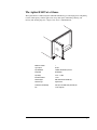
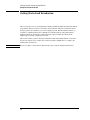
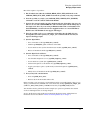
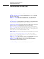
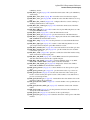
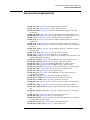
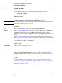
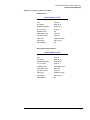
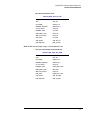
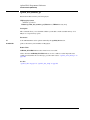
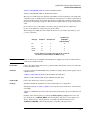
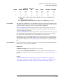
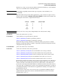
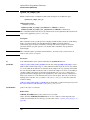
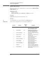
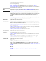
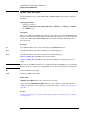
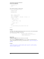
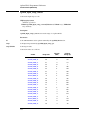
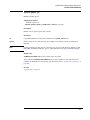
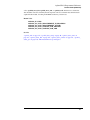
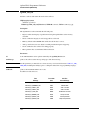
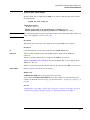
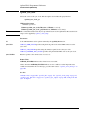
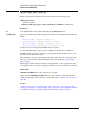
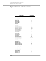
The Agilent E1439 at a Glance
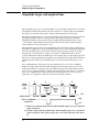
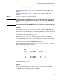
The Agilent E1439 95 MSa/s Digitizer with DSP and Memory provides high precision digitizing
for time and frequency domain applications along with signal conditioning, filtering, and
memory. The module plugs into a single C-size slot in a VXI mainframe.
E1
4
E1 38/
43
9
Number of Channels
1
Type of Inputs
50 ohm
Input Bandwidth
150 MHz, 36 MHz alias protected
Sample Rate
95 Msample/s
Input Range
−36 to +12 dBm
Raw ADC resolution
12 bits
VXI Bus Support
VME (and Local Bus E1439D only)
VXI Device Type
Register based
I/O Data Port (E1439D only)
Fiber optic serial FPDP (front panel data port)
Size
C-sized, single slot
3
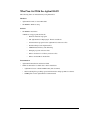
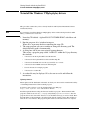
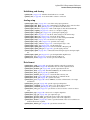
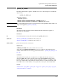
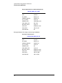
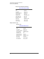
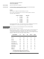
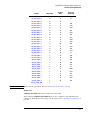
What You Get With the Agilent E1439
The following items are included with your Agilent E1439:
Hardware
•
Agilent E1439 ADC, C-size VXI module
•
CD-ROM for Windows setup
Software
•
CD-ROM for installation
A Windows setup program that installs:
•
Firmware installation program
•
The Agilent E1439 VXIplug&play libraries and drivers
•
Soft Front Panel program for the Agilent E1439 with source files
•
Web-based help for the Agilent E1439
•
AGDSP function library and online help
•
Example programs and source files
•
Microsoft Visual C++ C-library and source files
•
Microsoft Visual Basic header files
Documentation
•
Agilent E1439 Installation and Service Guide
•
Online documentation available after software installation:
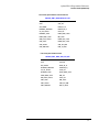
4
•
Agilent E1439 User’s Guide in PDF format (this document)
•
Web-based help files providing operational information and programmer’s reference
•
WinHelp files for the Agilent E1439 Soft Front Panel
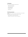
In This Book
This book documents the Agilent E1439 module. It provides:
•
hardware installation information
•
software installation information
•
getting started information
•
operational information
•
programmer’s reference
•
replaceable parts
Other Documentation
Installation and Service information is provided as a printed document as well as in this PDF
document.
After running the setup program the following documentation is available:
•
Web-based help files are available from the Start menu.
•
WinHelp for the Soft Front Panel is available from the application.
5
6
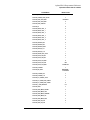
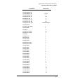
Contents
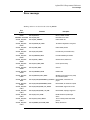
1
Installing the Agilent E1439
To inspect the Agilent E1439 . . . . . . . . . . . . . . . . . . . . . . . . . . . . . . . . . . .2
To install the Agilent E1439. . . . . . . . . . . . . . . . . . . . . . . . . . . . . . . . . . . .3
To clean fiber optic connectors . . . . . . . . . . . . . . . . . . . . . . . . . . . . . . . . .6
To store the module . . . . . . . . . . . . . . . . . . . . . . . . . . . . . . . . . . . . . . . . . .7
To transport the module . . . . . . . . . . . . . . . . . . . . . . . . . . . . . . . . . . . . . . .7
2
Getting Started with the Agilent E1439
Getting Started and Introduction . . . . . . . . . . . . . . . . . . . . . . . . . . . . . . .10
System Requirements . . . . . . . . . . . . . . . . . . . . . . . . . . . . . . . . . . . . . . . .11
To install the Windows VXIplug&play drivers . . . . . . . . . . . . . . . . . . . .12
To use the Resource Manager . . . . . . . . . . . . . . . . . . . . . . . . . . . . . . . . .13
To use the program group (Windows) . . . . . . . . . . . . . . . . . . . . . . . . . . .14
To use the VXIplug&play Soft Front Panel (SFP). . . . . . . . . . . . . . . . . .15
To use the example programs. . . . . . . . . . . . . . . . . . . . . . . . . . . . . . . . . .16
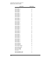
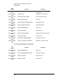
3
Using the Agilent E1439
Agilent E1439 overview. . . . . . . . . . . . . . . . . . . . . . . . . . . . . . . . . . . . . .20
Programming the Agilent E1439 . . . . . . . . . . . . . . . . . . . . . . . . . . . . . . .21
The measurement loop . . . . . . . . . . . . . . . . . . . . . . . . . . . . . . . . . . . . . . .23
Delay and phase in triggered measurements . . . . . . . . . . . . . . . . . . . . . .25
Magnitude trigger and magdwell time . . . . . . . . . . . . . . . . . . . . . . . . . . .28
Frequency and filtering. . . . . . . . . . . . . . . . . . . . . . . . . . . . . . . . . . . . . . .30
Using clock and sync . . . . . . . . . . . . . . . . . . . . . . . . . . . . . . . . . . . . . . . .31
Managing multiple modules . . . . . . . . . . . . . . . . . . . . . . . . . . . . . . . . . . .32
Transferring data . . . . . . . . . . . . . . . . . . . . . . . . . . . . . . . . . . . . . . . . . . .42
Fiber Optic Interface. . . . . . . . . . . . . . . . . . . . . . . . . . . . . . . . . . . . . . . . .43
4
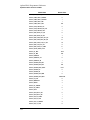
Agilent E1439 Programmer's Reference
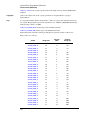
Introduction . . . . . . . . . . . . . . . . . . . . . . . . . . . . . . . . . . . . . . . . . . . . . . .54
Functions listed by class . . . . . . . . . . . . . . . . . . . . . . . . . . . . . . . . . . . . . .55
Functions listed by functional group . . . . . . . . . . . . . . . . . . . . . . . . . . . .60
Functions listed alphabetically . . . . . . . . . . . . . . . . . . . . . . . . . . . . . . . . .67
age1439_adc_clock . . . . . . . . . . . . . . . . . . . . . . . . . . . . . . . . . . . . . . . . .72
age1439_adc_divider . . . . . . . . . . . . . . . . . . . . . . . . . . . . . . . . . . . . . . . .73
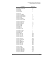
Contents
age1439_attrib_get . . . . . . . . . . . . . . . . . . . . . . . . . . . . . . . . . . . . . . . . . .74
age1439_cal_get . . . . . . . . . . . . . . . . . . . . . . . . . . . . . . . . . . . . . . . . . . . .75
age1439_clock_fs . . . . . . . . . . . . . . . . . . . . . . . . . . . . . . . . . . . . . . . . . . .76
age1439_clock_recover . . . . . . . . . . . . . . . . . . . . . . . . . . . . . . . . . . . . . .77
age1439_clock_setup . . . . . . . . . . . . . . . . . . . . . . . . . . . . . . . . . . . . . . . .78
age1439_close . . . . . . . . . . . . . . . . . . . . . . . . . . . . . . . . . . . . . . . . . . . . .86
age1439_combo_setup . . . . . . . . . . . . . . . . . . . . . . . . . . . . . . . . . . . . . . .87
age1439_data_memsize_get. . . . . . . . . . . . . . . . . . . . . . . . . . . . . . . . . . .88
age1439_data_scale_get . . . . . . . . . . . . . . . . . . . . . . . . . . . . . . . . . . . . . .89
age1439_data_setup . . . . . . . . . . . . . . . . . . . . . . . . . . . . . . . . . . . . . . . . .90
age1439_data_xfersize . . . . . . . . . . . . . . . . . . . . . . . . . . . . . . . . . . . . . . .96
age1439_driver_debug_level . . . . . . . . . . . . . . . . . . . . . . . . . . . . . . . . . .97
age1439_epoch_setup. . . . . . . . . . . . . . . . . . . . . . . . . . . . . . . . . . . . . . . .98
age1439_error_message . . . . . . . . . . . . . . . . . . . . . . . . . . . . . . . . . . . . .102
age1439_error_query . . . . . . . . . . . . . . . . . . . . . . . . . . . . . . . . . . . . . . .103
age1439_ext_sample_sync . . . . . . . . . . . . . . . . . . . . . . . . . . . . . . . . . . .104
age1439_fiber_clear . . . . . . . . . . . . . . . . . . . . . . . . . . . . . . . . . . . . . . . .106
age1439_fiber_error_clear . . . . . . . . . . . . . . . . . . . . . . . . . . . . . . . . . . .107
age1439_fiber_error_get . . . . . . . . . . . . . . . . . . . . . . . . . . . . . . . . . . . .108
age1439_fiber_LED_get . . . . . . . . . . . . . . . . . . . . . . . . . . . . . . . . . . . .110
age1439_fiber_rcv_signals_get . . . . . . . . . . . . . . . . . . . . . . . . . . . . . . .111
age1439_fiber_setup. . . . . . . . . . . . . . . . . . . . . . . . . . . . . . . . . . . . . . . .112
age1439_fiber_signal_get. . . . . . . . . . . . . . . . . . . . . . . . . . . . . . . . . . . .115
age1439_fiber_verify . . . . . . . . . . . . . . . . . . . . . . . . . . . . . . . . . . . . . . .116
age1439_fiber_xmt_BOF . . . . . . . . . . . . . . . . . . . . . . . . . . . . . . . . . . . .117
age1439_fiber_xmt_signals . . . . . . . . . . . . . . . . . . . . . . . . . . . . . . . . . .118
age1439_fiber_xmt_signals_get. . . . . . . . . . . . . . . . . . . . . . . . . . . . . . .119
age1439_filter_setup . . . . . . . . . . . . . . . . . . . . . . . . . . . . . . . . . . . . . . .120
age1439_filter_sync . . . . . . . . . . . . . . . . . . . . . . . . . . . . . . . . . . . . . . . .123
age1439_frequency_center_raw. . . . . . . . . . . . . . . . . . . . . . . . . . . . . . .125
age1439_frequency_center_raw_compute . . . . . . . . . . . . . . . . . . . . . . .127
age1439_frequency_setup . . . . . . . . . . . . . . . . . . . . . . . . . . . . . . . . . . .128
age1439_front_panel_clock_input . . . . . . . . . . . . . . . . . . . . . . . . . . . . .131
age1439_init . . . . . . . . . . . . . . . . . . . . . . . . . . . . . . . . . . . . . . . . . . . . . .132
age1439_input_autozero. . . . . . . . . . . . . . . . . . . . . . . . . . . . . . . . . . . . .134
age1439_input_offset . . . . . . . . . . . . . . . . . . . . . . . . . . . . . . . . . . . . . . .135
age1439_input_offset_save . . . . . . . . . . . . . . . . . . . . . . . . . . . . . . . . . .136
age1439_input_range_auto. . . . . . . . . . . . . . . . . . . . . . . . . . . . . . . . . . .137
age1439_input_range_convert . . . . . . . . . . . . . . . . . . . . . . . . . . . . . . . .138
age1439_input_setup . . . . . . . . . . . . . . . . . . . . . . . . . . . . . . . . . . . . . . .141
age1439_interrupt_restore . . . . . . . . . . . . . . . . . . . . . . . . . . . . . . . . . . .145
age1439_interrupt_setup . . . . . . . . . . . . . . . . . . . . . . . . . . . . . . . . . . . .146
age1439_lbus_mode . . . . . . . . . . . . . . . . . . . . . . . . . . . . . . . . . . . . . . . .148
age1439_lbus_reset . . . . . . . . . . . . . . . . . . . . . . . . . . . . . . . . . . . . . . . .150
age1439_meas_control . . . . . . . . . . . . . . . . . . . . . . . . . . . . . . . . . . . . . .151
age1439_meas_init . . . . . . . . . . . . . . . . . . . . . . . . . . . . . . . . . . . . . . . . .154
age1439_meas_start . . . . . . . . . . . . . . . . . . . . . . . . . . . . . . . . . . . . . . . .155
age1439_meas_status_get . . . . . . . . . . . . . . . . . . . . . . . . . . . . . . . . . . .156
8
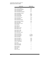
Contents
age1439_options_get . . . . . . . . . . . . . . . . . . . . . . . . . . . . . . . . . . . . . . .157
age1439_product_id_get . . . . . . . . . . . . . . . . . . . . . . . . . . . . . . . . . . . .158
age1439_read . . . . . . . . . . . . . . . . . . . . . . . . . . . . . . . . . . . . . . . . . . . . .159
age1439_read_raw . . . . . . . . . . . . . . . . . . . . . . . . . . . . . . . . . . . . . . . . .162
age1439_reference_clock . . . . . . . . . . . . . . . . . . . . . . . . . . . . . . . . . . . .165
age1439_reference_prescaler . . . . . . . . . . . . . . . . . . . . . . . . . . . . . . . . .166
age1439_reset . . . . . . . . . . . . . . . . . . . . . . . . . . . . . . . . . . . . . . . . . . . . .167
age1439_reset_hard . . . . . . . . . . . . . . . . . . . . . . . . . . . . . . . . . . . . . . . .168
age1439_revision_query. . . . . . . . . . . . . . . . . . . . . . . . . . . . . . . . . . . . .169
age1439_self_test . . . . . . . . . . . . . . . . . . . . . . . . . . . . . . . . . . . . . . . . . .170
age1439_serial_number . . . . . . . . . . . . . . . . . . . . . . . . . . . . . . . . . . . . .172
age1439_smb_clock_output . . . . . . . . . . . . . . . . . . . . . . . . . . . . . . . . . .173
age1439_state_recall . . . . . . . . . . . . . . . . . . . . . . . . . . . . . . . . . . . . . . .174
age1439_state_save . . . . . . . . . . . . . . . . . . . . . . . . . . . . . . . . . . . . . . . .175
age1439_status_get. . . . . . . . . . . . . . . . . . . . . . . . . . . . . . . . . . . . . . . . .176
age1439_sync_clock. . . . . . . . . . . . . . . . . . . . . . . . . . . . . . . . . . . . . . . .178
age1439_sync_direction . . . . . . . . . . . . . . . . . . . . . . . . . . . . . . . . . . . . .179
age1439_sync_output . . . . . . . . . . . . . . . . . . . . . . . . . . . . . . . . . . . . . . .180
age1439_trigger_delay_actual_get. . . . . . . . . . . . . . . . . . . . . . . . . . . . .181
age1439_trigger_phase_actual_get . . . . . . . . . . . . . . . . . . . . . . . . . . . .182
age1439_trigger_setup . . . . . . . . . . . . . . . . . . . . . . . . . . . . . . . . . . . . . .183
age1439_vcxo. . . . . . . . . . . . . . . . . . . . . . . . . . . . . . . . . . . . . . . . . . . . .187
age1439_vxi_clock_output. . . . . . . . . . . . . . . . . . . . . . . . . . . . . . . . . . .188
age1439_wait . . . . . . . . . . . . . . . . . . . . . . . . . . . . . . . . . . . . . . . . . . . . .189
Equivalent numeric values for variables . . . . . . . . . . . . . . . . . . . . . . . .190
Commands which halt active measurements . . . . . . . . . . . . . . . . . . . . .198
Error messages . . . . . . . . . . . . . . . . . . . . . . . . . . . . . . . . . . . . . . . . . . . .199
Default values . . . . . . . . . . . . . . . . . . . . . . . . . . . . . . . . . . . . . . . . . . . . .201
VXIplug&play Syntax Quick Reference . . . . . . . . . . . . . . . . . . . . . . . .203
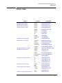
5
Module Description
Front Panel Description . . . . . . . . . . . . . . . . . . . . . . . . . . . . . . . . . . . . .208
VXI backplane connections . . . . . . . . . . . . . . . . . . . . . . . . . . . . . . . . . .209
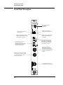
Block diagram and description. . . . . . . . . . . . . . . . . . . . . . . . . . . . . . . .211
6
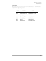
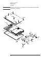
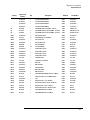
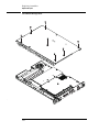
Replacing Assemblies
Replaceable parts . . . . . . . . . . . . . . . . . . . . . . . . . . . . . . . . . . . . . . . . . .220
Glossary . . . . . . . . . . . . . . . . . . . . . . . . . . . . . . . . . . . . . . . . . . . . . . . . .227
Index . . . . . . . . . . . . . . . . . . . . . . . . . . . . . . . . . . . . . . . . . . . . . . . . . . .229
Need Assistance?. . . . . . . . . . . . . . . . . . . . . . . . . . . . . . . . . . . . . . . . . .235
About this edition . . . . . . . . . . . . . . . . . . . . . . . . . . . . . . . . . . . . . . . . .236
9
Contents
10
1
1
Installing the Agilent E1439
Installing the Agilent E1439
To inspect the Agilent E1439
To inspect the Agilent E1439
The Agilent E1439 single channel VXI ADC Module was carefully inspected both mechanically
and electrically before shipment. It should be free of marks or scratches and it should meet its
published specifications upon receipt.
If the module was damaged in transit, do the following:
•
Save all packing materials.
•
File a claim with the carrier.
•
Call your Agilent Technologies sales and service office.
2
Installing the Agilent E1439
To install the Agilent E1439
To install the Agilent E1439
Caution
To protect circuits from static discharge, observe anti-static techniques whenever handling
the Agilent E1439 VXI ADC Module.
1. Set up your VXI mainframe. See the installation guide for your mainframe.
2. Select a slot in the VXI mainframe for the E1439 module.
The Agilent E1439D module’s local bus receives ECL-level data from the
module immediately to its left and outputs ECL-level data to the module
immediately to its right. Every module using the local bus is keyed to prevent
two modules from fitting next to each other unless they are compatible. If you
will be using the local bus, select adjacent slots immediately to the left of the
data-receiving module. If the VXI bus is used, maximum data rates will be
reduced but the module can be placed in any available slot.
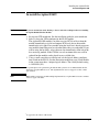
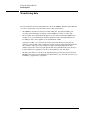
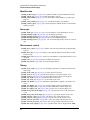
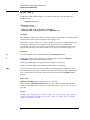
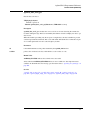
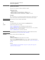
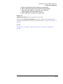
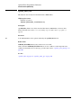
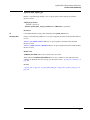
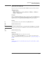
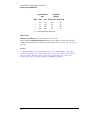
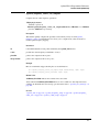
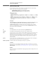
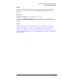
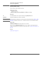
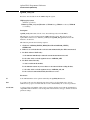
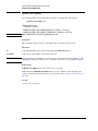
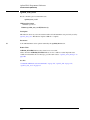
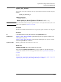
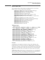
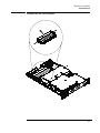
3. Using a small screwdriver or similar tool, set the logical address configuration switch on the E1439. (See the illustration on the next page.) Each module
in the system must have a unique logical address. The factory default setting
is 1100 0000 (192).
Note
For optimal phase noise performance in multi-module systems it is recommended that the first
channel be an Agilent E1439C or D1. The Agilent E1439C does not support local bus or fiber
optic transfers.
Note
Multi-module systems may include multiple Agilent E1438s or Agilent E1439s but not a mixture
of the two types of modules.
1
As opposed to the older A or B models.
3
Installing the Agilent E1439
To install the Agilent E1439
Logical Address
0
1
4. Set the mainframe’s power switch to off (0).
Caution
Installing or removing the module with power on may damage components in the module.
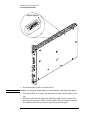
5. Place the module’s card edges (top and bottom) into the module guides in the
slot.
6. Slide the module into the mainframe until the module connects firmly with
the backplane connectors. Make sure the module slides in straight and that the
insertion/extraction levers are pressed parallel to the front panel.
4
Installing the Agilent E1439
To install the Agilent E1439
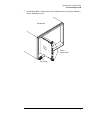
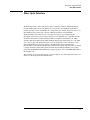
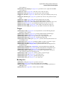
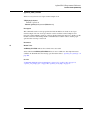
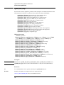
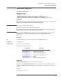
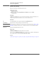
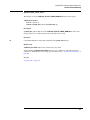
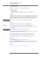
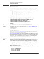
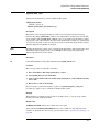
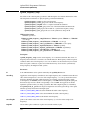
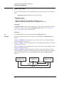
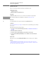
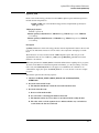
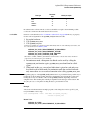
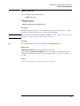
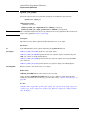
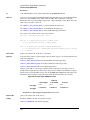
7. Attach the module’s front panel to the mainframe chassis using the module’s
captive mounting screws.
VXI Mainframe
E1
4
E1 38/
43
9
Slotted
Captive Screws
Power Switch
5
Installing the Agilent E1439
To clean fiber optic connectors
To clean fiber optic connectors
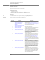
The Agilent E1439D has a fiber optic serial FPDP (front panel data port). Since the data transmits
via light, the fiber optic connections must be clean. The following procedure describes how to
clean fiber optic connectors.
Caution
Do not use any type of foam swab to clean optical fiber ends. Foam swabs can leave filmy
deposits on fiber ends.
1. Apply pure isopropyl alcohol to a clean lint-free cotton swab or lens paper.
Cotton swabs can be used as long as no cotton fibers remain on the fiber end after cleaning.
2. Clean the connector while avoiding the ends of the fiber.
3. Apply isopropyl alcohol to a new clean lint-free cotton swab or lens paper.
4. Clean the fiber end with the swab or lens paper.
Do not scrub during this initial cleaning because grit can be caught in the swab and become a
gouging element.
5. Immediately dry the fiber end with a clean, dry, lint-free cotton swab or lens paper.
6. Blow across the connector end face from a distance of 6 to 8 inches using filtered, dry,
compressed air. Aim the compressed air at a shallow angle to the fiber end face.
Nitrogen gas or compressed dust remover can also be used.
Caution
Do not shake, tip, or invert compressed air canisters because this releases particles in the
can into the air. Refer to instructions provided on the compressed air canister.
7. As soon as the connector is dry, connect or cover it for later use.
Note
To order multimode LC fiber optic cables, call Stratos Lightwave at (708) 867-9600
(http://www.stratoslightwave.com) or call Fiber Instrument at (800) 500-0347
(http://www.fisfiber.com).
6
Installing the Agilent E1439
To store the module
To store the module
Store the module in a clean, dry, and static free environment.
For other requirements, see storage and transport restriction in “Technical Specifications”.
To transport the module
•
•
Package the module using the original factory packaging or packaging identical to the factory packaging.
If returning the module to Agilent Technologies for service, attach a tag
describing the following:
•
Type of service required
•
Return address
•
Model number
•
Full serial number
In any correspondence, refer to the module by model number and full serial number.
Caution
•
Mark the container FRAGILE to ensure careful handling.
•
If necessary to package the module in a container other than original packaging, observe the
following (use of other packaging is not recommended):
•
Wrap the module in heavy paper or anti-static plastic.
•
Protect the front panel with cardboard.
•
Use a double-wall carton made of at least 200-pound test (32 ECT) material.
•
Cushion the module to prevent damage. For example, several layers of plastic bubble
wrap is usually sufficient.
Do not use styrene pellets in any shape as packing material for the module. The pellets do
not adequately cushion the module and do not prevent the module from shifting in the
carton. In addition, the pellets create static electricity that can damage electronic
components.
7
Installing the Agilent E1439
To transport the module
8
2
2
Getting Started with the Agilent E1439
Getting Started with the Agilent E1439
Getting Started and Introduction
Getting Started and Introduction
This section helps you get your Agilent E1439 running and making simple measurements without
programming. It shows you how to install the software libraries and how to run the Soft Front
Panel program. It also introduces you to the example programs. The Host Interface Library is
available as a Windows Library that communicates with the hardware using VISA (Virtual
Instrument Software Architecture). VISA is the input-output standard upon which all the
VXIplug&play software components are based..
This section assumes you have already installed the module in the VXI mainframe as shown in
the previous chapter. It also assumes that you have installed a VXI interface according to the
manufacturer’s instructions.
Note
Be sure to read the readme file for important up-to-date software installation information.
10
Getting Started with the Agilent E1439
System Requirements
System Requirements
System Requirements (Microsoft Windows)
•
A Pentium-class personal computer:
•
Microsoft Windows 2000, or NT.
•
One of the following interfaces:
•
HP/Agilent FireWire −E8491B IEEE-1394 PC Link to VXI
•
National Instruments PCI MXI-2
•
Other VISA compliant VXI interface
•
VISA (Virtual Instrument Software Architecture) library
•
The computer must have a CD ROM drive for the installation media
•
One of the following Web browsers:
•
Microsoft Internet Explorer 4.0 or greater
•
Netscape Navigator 4.08 or greater
11
Getting Started with the Agilent E1439
To install the Windows VXIplug&play drivers
To install the Windows VXIplug&play drivers
This procedure assumes that you have already installed a VISA (Virtual Instrument Software
Architecture) library.
Note
If you attempt to install the Windows VXIplug&play drivers without having installed a VISA
library you will receive a fatal error.
1. Insert the CD labeled: “Agilent E1439 VXI 70MHz IFADC with filters and
memory”
2. Run the program: drive:\windows\setup.exe
Where drive represents the drive containing the setup CD.
3. The setup program asks you to confirm or change the directory path. The
default directory path is recommended.
4. A dialog box asks if you want to install startup shortcuts
This creates a program group called “AGE1439” within the Vxipnp directory
that includes:
•
A shortcut to run the Agilent E1439 Soft Front Panel
•
A shortcut for the Agilent E1439 web-based online help file
•
A shortcut for the PDF version of the Agilent E1439 User’s Guide
•
A shortcut for the AGDSP web-based online help file
•
Several shortcuts for example programs
•
A shortcut for a readme file
5. A readme file may be displayed. If so, be sure to read it and follow the
instructions.
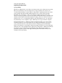
Updating firmware
Future updates will be distributed on the Web. To check your current revision run the Info Utility
or check Help/About in the Soft Front Panel program.
To check for new revisions access the Agilent Technologies Web page
http://www.agilent.com/ and search for "E1439".
Install the updated firmware using the firmware installation program—FirmwareInstall. This
program’s default location is drive:\vxipnp\win[95|NT]\age1439\firmware. Start the
program, then use the "Select File" button to locate the firmware image you want to install. Enter
the VXI address of the instrument to be updated and click the "Update" button. The installation
will take one or two minutes. This program requires VISA to be installed on the host computer.
12
Getting Started with the Agilent E1439
To use the Resource Manager
To use the Resource Manager
The Resource Manager is a program from your hardware interface manufacturer. It looks at the
VXI mainframe to determine what modules are installed. You need to run it every time you power
up. If you get the message: "VISUCCESS_DEVICE_NPRESENT" then run the Resource
Manager.
Before running the Agilent E1439 software make sure that your hardware is configured correctly
and that the Resource Manager runs successfully. Before using your measurement system, you
must set up all of its devices, including setting their addresses and local bus locations. No two
devices can have the same address. Usually addresses 0 and 1 are taken by the Resource Manager
and are not available.
For more information about the Resource Manager, see the documentation with your hardware
interface.
Note
Most Resource Managers will recognize the manufacturer and model number of the
Agilent E1439 but if your interface requires that you enter this information manually, use the
following:
Manufacturer number: 4095 (Hex FFF)
Model number: 699 (Hex 2BB)
13
Getting Started with the Agilent E1439
To use the program group (Windows)
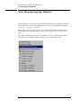
To use the program group (Windows)
If you installed the program group using the default method during the installation procedure, you
have a shortcut for a program group similar the one below. Access it through the Start button:
Programs \ Vxipnp \ age1439
This program group contains shortcuts that access the Soft Front Panel program, the User’s
Guide, online help, and example programs. The following pages provide an overview of these
items.
If you did not install the program group, executable files for each of the items represented by
group shortcuts are available in the drive:\vxipnp directory and its subdirectories.
14
Getting Started with the Agilent E1439
To use the VXIplug&play Soft Front Panel (SFP)
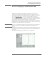
To use the VXIplug&play Soft Front Panel (SFP)
In a Windows environment, the Soft Front Panel is the best place to start to explore the
capabilities of the Agilent E1439. The Soft Front Panel is useful for checking your system to
make sure that it is installed correctly and that all of its parts are working. You can also use it to
make actual measurements, since it accesses most of the Agilent E1439’s functionality.
Select the
shortcut in your program group to start the program. This
assumes you have already installed all required hardware and drivers (including VISA) and have
run the configurator and Resource Manager required by your hardware interface.
If prompted for the resource descriptor, use the default "VXI::192" unless the logical address of
the Agilent E1439 has been changed from its default setting of 192. If it has been changed, type
the appropriate logical address instead of 192, then press OK.
Note
You can also run the Agilent E1439 Front Panel in a simulation mode without an Agilent E1439
module, a hardware interface, or VISA libraries by typing "sim" in place of the resource
descriptor.
The Agilent E1439 Front Panel Help, available from the Soft Front Panel Help menu, describes
the capability of the Soft Front Panel and has links to functions that control and define many of
the parameters.
The source files for this program are provided for you to use as sample code.
15
Getting Started with the Agilent E1439
To use the example programs
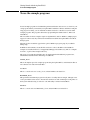
To use the example programs
Several example programs are included that perform useful tasks and can serve as a basis for your
own programs. When you installed your Agilent E1439 Windows libraries and drivers using the
setup program or utility, you also installed executable and source code files for several useful
example programs. The programs demonstrate programming the module with "C", Microsoft
Visual Basic,
The executables for these examples require an Agilent E1439 and, for Windows, VXIplug&play
support; in other words, they will not run in simulation mode like the Agilent E1439 Soft Front
Panel program.
Shortcuts for the executables appear in the age1439 Windows program group if you added it
during setup.
In Windows environments, executable files and source code for the Microsoft Visual Basic
examples are installed in the drive:\vxipnp\win[95|NT]\age1439\vb directory. The "C" examples
are in the ...\age1439\msc\examples directory.
The group of programs described here may be supplemented with additional programs later,
which will be described in the online help or readme file.
ACVolts_32.exe
This is the simplest practical complete program using the Agilent E1439, and it functions like an
AC voltmeter. It is written in Visual Basic.
acvolts.exe
This is a console version of acvolts_32.exe, written in Microsoft Visual C++.
Benchmark_32.exe
This performance benchmark program is really more of a utility than an example, although source
code is provided. It allows users to measure data transfer rates and command processing times on
their system without having to write new code. The utility is written in Visual Basic.
bench.exe
This is a console version of Benchmark_32.exe, written in Microsoft Visual C++.
16
Getting Started with the Agilent E1439
To use the example programs
multchan_32.exe
This example shows how to synchronize two modules to achieve simultaneous sampling, filter
decimation, and matched local oscillator phase. It is written in Visual Basic.
info.exe
This example shows how to retrieve option and revision information from an Agilent E1439, and
it doubles as a handy utility. It is written as a console program in Microsoft Visual C++.
interrupt.exe
This example shows how to set up and trap a VXI interrupt to indicate an error condition in the
Agilent E1439. It is written as a console program in Microsoft Visual C++.
17
Getting Started with the Agilent E1439
To use the example programs
18
3
3
Using the Agilent E1439
Using the Agilent E1439
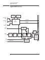
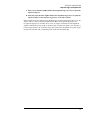
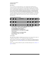
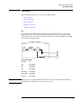
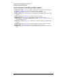
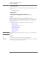
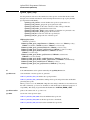
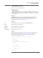
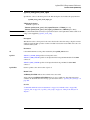
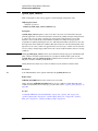
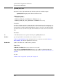
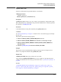
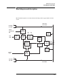
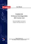
Agilent E1439 overview
Agilent E1439 overview
100 MHZ
VCXO
102.4 MHz
VCXO
Intermodule
clock
VXI CLOCK
Intermodule
sync
Clock
Generation
VXI SYNC
Ext
Trigger
VXI Backplane
Ext
Clock/Ref
Trigger
Detection
VXI bus
Interface
Analog
In
XMT
RCV
Attenuators
(E1439B/D only)
20
Anti-alias
Filter
Sampling
ADC
Zoom and
Decimation
Filtering
FIFO
Memory
Fiber Optic
FPDP Interface
(E1439B/D only)
Local bus
Interface
(not present
in the E1439C)
Using the Agilent E1439
Programming the Agilent E1439
Programming the Agilent E1439
The Agilent E1439 is shipped with software and documentation to support a broad set of choices
of controllers, I/O interfaces, programming languages, and operating systems. By virtue of its
compliance to the VXIplug&play standard, the E1439 is most easily controlled in an environment
conforming to one of the supported VXIplug&play frameworks. However, support is also
supplied for other common hardware and software environments. The relationship among the
various levels of programming is shown in the diagram below.
Windows & Visual Basic
C Programming
WIN
C-Function Library
Hardware Registers
Windows framework
The primary development environment supported by the E1439 is the VXIplug&play WINNT
framework specifications. It requires the following resources prior to the installation of the
E1439:
•
An embedded or a stand-alone Pentium-class PC
•
Microsoft Windows 2000, or NT
•
VISA interface library
•
VISA compatible hardware interface
•
Microsoft Visual C++ and/or Microsoft Visual Basic development system.
Additional details on the WIN framework can be found in the VXIplug&play VPP-2 System
Frameworks Specification, Revision 2.0.
In addition to the C source code files, the E1439 includes compiled libraries, example programs,
an interactive soft front panel program, online help files, and an installation program. The
interactive soft front panel program allows the E1439 to be turned on, verified, and used for
simple tasks without writing any user programs.
21
Using the Agilent E1439
Programming the Agilent E1439
C programming
The E1439 is shipped with a source library of C-functions that can be called from user programs.
This elevates the interface above the register level so the programmer does not have to be
concerned with such things as register addresses and packing or splitting parameters into 16-bit
register lengths. The library includes ANSI compliant source code files with all machine
dependent code constrained to a single source file. By re-writing selected portions of the
machine.h file, the programmer can create and compile an E1439 library that is compatible with
virtually any development environment using the C language. The most common reason for rewriting machine.h is to accommodate I/O libraries other than VISA. In some cases, the library
may need merely to be re-compiled to target a different processor type for the host computer.
Porting the E1439 library to a different computer environment is likely to be a fairly straight
forward task. However, some of the higher level tools shipped with the E1439 may not be as
easily ported. The interactive soft front panel and some example programs include human
interfaces that depend on certain display and keyboard support which may be system dependent.
Although source code is included for these applications, porting them to a different environment
may present a greater problem than porting the library itself. The installation utilities are
specifically targeted to operate on the supported development environments and may not be
available in other environments.
22
Using the Agilent E1439
The measurement loop
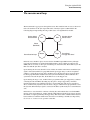
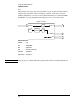
The measurement loop
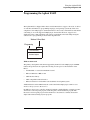
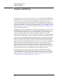
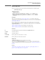
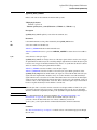
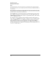
The measurement loop progresses through four states. The transition from one state to the next is
tied to the transition of the Sync signal. The effect of the Sync signal is summarized in the
following diagram representing the four possible states of an Agilent E1439 module.
No data collected
Old data available
IDLE
Assert
Release
(Block Mode)
Data collected and output
ARM
New data collected
Old data cleared
Release
Measure
Assert
Trigger
Data collected
Pre-trigger data cleared
In the Idle state, the E1439 places no new data into the FIFO output buffer memory although
previously measured data is retained in the buffer memory and is available for output via the
VME (and also local bus, or fiber optic transmitter port on the E1439D). The module stays in the
Idle state until the Sync line is asserted.
Upon entering the Arm state the E1439 clears old data. It remains in the Arm state until the Sync
signal is released. If an E1439 is programmed with a pre-trigger delay, it collects enough data
samples to satisfy this pre-trigger delay, and then releases the Sync line. If no pre-trigger delay
has been programmed, the module releases the Sync line immediately. When all E1439s in a
system have released the Sync line, the module moves to the Trigger state.
Upon entering the Trigger state, an E1439 that is programmed with a pre-trigger delay continues
collecting data into the FIFO, discarding any data prior to the pre-trigger delay. An E1439
remains in the Trigger state until the Sync line is asserted. The Sync line may be asserted by a
direct command or by any E1439 that encounters a trigger condition and is programmed to assert
the Sync line. When the Sync signal is asserted, all modules synchronously move to the Measure
state.
In the Measure state, the E1439 continues collecting data and sends the data saved in the FIFO
memory to the selected I/O port, starting with the sample indicated by the trigger arrival, offset by
the number of samples specified by the trigger delay. This data transfer continues until all data has
been transferred or until the module meets the criteria for returning to the Idle state imposed by
block mode or continuous mode operation constraints.
23
Using the Agilent E1439
The measurement loop
Modules programmed for block mode operation assert the Sync line until a complete block of
data, including any pre-programmed pre- or post-trigger delay, has been collected and is available
to the I/O port. The module then releases the Sync line. The module returns to the Idle state when
the block of data has been collected.
In continuous mode, a module releases sync immediately but moves to the Idle state only if
explicitly programmed to do so or if the FIFO data buffer overflows because data cannot be read
from the I/O port fast enough.
The measurement loop in multi-module systems
The following rules generally apply to transitions between states when multiple modules share a
Sync signal:
•
If any one module asserts the Sync line, a synchronous state transition occurs for all modules
in a system.
•
All modules in a system must have released the Sync line in order to bring about a
synchronous transition to Trigger state.
•
In block mode, each module releases the Sync line after its block of data has been collected.
Immediately upon entering the Measure state in continuous mode, each module releases the
Sync line. It continues to collect and output data until it is programatically signaled to stop or
until the FIFO overflows. With the Sync line released it is then possible to change the center
frequency for one or multiple modules without interrupting the measurement. See
“Synchronizing changes in multi-module systems” on page 39.
•
A module may be programmed explicitly to inhibit its transition to the Arm state despite Sync
transitions.
•
In addition to controlling the progression through the four module states, the Sync signal is
used to synchronize the decimation counters and local oscillators of multiple E1439 modules.
24
Using the Agilent E1439
Delay and phase in triggered measurements
Delay and phase in triggered measurements
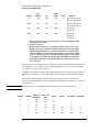
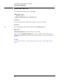
It is important to note that the trigger delay is specified in terms of output samples. When using
the digital filters within the E1439 to reduce the sample rate, there are multiple ADC samples
corresponding to each output sample. In order to determine the relationship between the first
output sample of a block and the actual ADC sample where the trigger occurred, you must read
the actual delay from the module using age1439_trigger_delay_actual_get.
This relationship varies from block to block and is a function of the particular value of counters
within the digital filters at the time the trigger occurs. Thus the actual delay from the trigger event
is the delay from age1439_trigger_delay_get multiplied by 2sigBw (from age1439_filter_bw_get
if filter decimation is used, or 2(sigBw-1) if filter decimation is off). From this value, subtract the
value returned by age1439_trigger_delay_actual_get. The result is in periods of the ADC
sample clock. Special considerations apply in multi-module systems. See “Trigger and phase in
multi-module systems” on page 40.
When doing a zoomed measurement, it may also be helpful to know the phase of the digital LO at
the time the trigger occurred, since the LO is also running continuously and it has an arbitrary
phase relationship with the trigger event. age1439_trigger_phase_actual_get returns the phase
of the LO at the trigger point. The LO phase could be used in time domain averaging of blocks, or
other operations involving zoomed blocks of data, so that the varying phase of the LO can be
removed from the calculation.
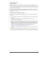
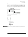
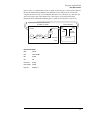
The trigger_delay value is the time, measured in output samples, from the desired trigger point to
the start of the time record. The trigger_delay_actual value is the time, measured in input
samples, from the desired trigger point to the actual trigger point.
Start of
time record
Desired
trigger point
Actual
trigger point
signal
trigger_delay
trigger_delay_
actual
time
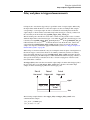
The following example illustrates how trigger_delay and trigger_delay_actual can be
combined. In this example:
filter_bw=4 (2.4 MHz span)
filter_decimate = 1 (on)
25
Using the Agilent E1439
Delay and phase in triggered measurements
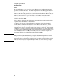
trigger_delay = -2 (a pre-trigger delay of 2)
Because the filter_bw is 4 with decimation on, there are 16 input samples for every output sample
for a decimation rate of 24
.
trigger_delay_actual=0 (or 0/16=0 output samples)
desired trigger
trigger
level
actual trigger
signal
1
2
3
4
trigger_delay_actual=4 (or 4/16=1/4 output samples)
desired trigger
1
trigger
actual trigger level
2
3
4
trigger_delay_actual=8 (or 8/16=1/2 output samples)
desired trigger
1
trigger
level
actual trigger
2
3
4
The phase returned is the phase of the LO at the actual trigger point, not the desired trigger point.
The following example illustrates how age1439_phase_actual_get might be used. In this
example, the input signal is a sine wave at a frequency of 4 MHz. The module is set up as follows:
frequency_center = 4.5 MHz
filter_bw = 4 (2.4 MHz span)
filter_decimate = 1 (on)
trigger_type = 1 (ADC trigger)
trigger_delay = -32 (a pre-trigger delay of 32)
trigger_adclevel = 0
data_type = 1 (complex)
After the measurement is completed, call age1439_delay_actual_get and age1439_phase_
actual_get. In this example, the values returned happened to be:
delay_actual = 16
phase_actual = 19697
26
Using the Agilent E1439
Delay and phase in triggered measurements
Due to the pretrigger delay of 32, the desired trigger point would have been at the 32nd sample of
the time record. However, the delay_actual value of 16 indicates that the sample corresponding
to the actual trigger is number 32+16/24 or the 33rd sample. The measured phase of the 33rd
(complex) sample, found via the atan2() function, is 159 degrees. The phase of the LO at this
sample is 19697*360/65536=108 degrees. Adding these together to get the corrected phase of the
input signal results in 267 degrees = -93 degrees, which is close to the expected phase of a sine
wave triggered at its zero-crossing, which would be -90 degrees.
27
Using the Agilent E1439
Magnitude trigger and magdwell time
Magnitude trigger and magdwell time
The magnitude trigger operates on the magnitude of a (possibly filtered) signal. For a real signal,
the magnitude is merely the absolute value of the signal. For a complex signal, the magnitude is
the square root of the sum of the squares of the real and imaginary parts of the signal.
Because the magnitude trigger can operate on the filtered signal, the trigger can be more selective
regarding what signals will cause a trigger than the ADC trigger. Only signals in the filter
bandwidth around the center frequency will be considered when determining when a trigger
occurs. Signals outside the filter's passband will be filtered out before the magnitude trigger
circuit and will not cause any triggers to occur.
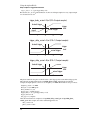
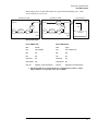
The magnitude trigger's behavior can be modified by the magDwell time. The magDwell time is
the number of samples that a signal's magnitude must be low (i.e., below the magLevel threshold)
before the magnitude trigger circuit will recognize the signal as being low. This can facilitate
triggering off of a burst signal; for example, a tone burst or a TDMA burst. Due to the zero
crossings within the tone burst, the ADC trigger can not reliably trigger on the leading edge of the
burst. If you set the magDwell time longer than any potential drop outs within a burst and shorter
than the gap between bursts, the magnitude trigger can easily catch the leading edge of a tone
burst.
For a magnitude trigger with positive slope, the signal must be low for at least a magDwell
number of samples. After that, the module will trigger the next time the signal goes above the
magLevel threshold. For a negative slope, the module will trigger the first time that the signal is
low for at least a magDwell number of samples after being high. Note that in this case, the trigger
will occur a magDwell period of time after the end of the tone burst. You can use a negative
trigger delay to compensate for this and to capture the end of the tone burst.
Signal
Envelope
or
Level
A
magDwell times:
Output of magnitude
comparators
B
Possible
Positive
Trigger
Points
C
Positive
Trigger
Point
D
Negative
Trigger
Point
Time
High
Low
A. Time A is less than the magDwell time. The magnitude trigger does not recognize the
signal as being low.
B. Time B is longer than the magDwell time. The magnitude trigger does recognize the
signal as being low and a positive trigger may occur on the rising edge at the end of
B.
28
Using the Agilent E1439
Magnitude trigger and magdwell time
C. Time C is less than the magDwell time. The magnitude trigger does not recognize the
signal as being low
D. Time D is longer than the magDwell time. The magnitude trigger does recognize the
signal as being low and a negative trigger may occur at the end of D.
In the example shown, the signal is below the threshold at A and C, but in both of these cases, the
signal is low for a time less than the magDwell time. Hence the magnitude trigger does not
recognize the signal as low and these do not cause any triggers. About half way through B, the
signal has remained low long enough so that the trigger recognizes the signal as low. After this, a
positive trigger would occur on the next rising edge of the signal's magnitude. A negative trigger
would occur at the end of D, a magDwell period of time after the falling edge.
29
Using the Agilent E1439
Frequency and filtering
Frequency and filtering
The Agilent E1439’s center frequency is normally set at zero (baseband path) and 70 MHz for the
IF signal path. However, you may set the center frequency to a non-zero value in order to examine
a narrower span away from baseband (zoom measurement).The frequency band of interest,
represented by digitized time data samples from the ADC, is mixed with the E1439 digital LO, a
complex exponential, at the desired center frequency. As a result, the frequency band of interest in
the input signal is shifted to a complex signal centered around dc. See “Synchronizing changes in
multi-module systems” on page 39 for special considerations with respect to changing the center
frequency in multi-module systems.
The default filter for E1439 measurements is an analog anti-alias filter. However, you may further
isolate the frequency band of interest for more detailed analysis by using digital filtering. A
decimating digital filter simultaneously decreases the bandwidth of the signal and decreases the
sample rate. The built-in digital filters conform to the Nyquist sampling criterion, which
guarantees that the output sample rate may be reduced by the same factor as the signal bandwidth
reduction while still maintaining a complete representation of the underlying bandlimited signal.
For each octave step in bandwidth reduction (except for the first octave), the E1439 digital filters
automatically reduce the data rate by discarding alternate output samples. This process, called
decimation, results in an output sample rate that is nominally four times the signal bandwidth
whenever sigBw>0. This is still double the theoretical rate necessary to fully characterize the band
limited signal. However, because the digital filters do not have a perfectly abrupt cutoff, the
sample rate cannot be reduced to the theoretical limit without some aliasing of signals in the
transition frequency band of the filters. In many applications, this limited aliasing potential is not
important. For this reason you may optionally choose to apply a final factor-of-two decimation.
See the Technical Specifications for detailed information on the digital filter shapes.
The decimation process used to reduce the output sample rate is driven from a "decimation
counter" that keeps track of which samples to save and which ones to discard for each of the
octave bandwidth reduction filter stages. In multi-module systems where synchronous sampling is
required, the decimation counters in all the modules must be synchronous with each other. See
“Synchronizing changes in multi-module systems” on page 39.
30
Using the Agilent E1439
Using clock and sync
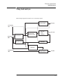
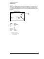
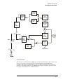
Using clock and sync
The following diagram shows the flow of clock and sync signals:
VXI Clock Output
VXI Clock
EXT Clock/Ref
BNC
Intermodule Clock
SMB
Font Panel Clock
Reference Clock
Reference Prescaler
ADC Clock
VCXO
VCXO Freq
ADC Clock
ADC Divider
SMB Clock Output
SYNC Clock
Intermodule Sync
SMB
SYNC Output
SYNC Direction
VXI SYNC
31
Using the Agilent E1439
Managing multiple modules
Managing multiple modules
Sharing Reference and Sync signals in multi-module systems
The Agilent E1439 supports synchronous operation among multiple E1439s by using a shared
ADC clock and Sync signal to drive all the modules in a system. The shared Sync signal is used to
synchronize critical operations including arming, triggering the beginning of data collection,
setting a common phase of the local oscillators for zoom operation, and forcing concurrent output
sample times when decimation is used. The Sync line transitions are constrained to not occur
during the critical (setup and hold) regions of the external reference. The reference operates at
1/38 of the internal ADC clock, typically 95 MHz for a E1439 module. The reference can be
either generated within the master module or an external reference can be fed into the master
module through a front panel BNC.
Note
For optimal phase noise performance in multi-module systems it is recommended that the first
channel be an Agilent E1439C or D1. The Agilent E1439C does not support local bus or fiber
optic transfers.
Note
Multi-module systems may include multiple Agilent E1438s or Agilent E1439s but not a mixture
of the two types of modules.
Clock distribution
When shared, the reference clock and sync lines are distributed among modules either on the VXI
backplane using the ECL Trigger lines, or on the front panel using the SMB Clock/Ref extender
connectors. When VXI backplane distribution is used with more than one VXI mainframe, the
front panel Intermodule Clock and Sync connectors can be used to distribute clock and Sync lines
from one mainframe to another.
Since the Sync transition timing relative to the reference input is critical, the module driving the
Sync line should ideally be the same one identified as the master. However, when using backplane
distribution, any E1439 in the same mainframe as the master can drive the Sync line.
When using the multi-sync mode of operation, the selection of front panel or backplane
distribution of reference and Sync signals involves the following considerations:
•
Backplane distribution requires the use of the ECL Trigger lines on the backplane, which are
then unavailable to other modules.
•
The overall time skew between the arrival of ADC clock edges is smaller when using
backplane distribution, particularly if the master (or buffer) module is physically located in
the center of the group of E1439 modules.
•
Backplane distribution is more susceptible to pickup of jitter on the ADC clock from other
digital activity on the VXI backplane. The extent of this pickup depends on the mainframe and
on the other modules in the mainframe. One important step in reducing this pickup is to
disable, whenever possible, the 10 MHz VXI clock generated by the slot-0 controller.
1
As opposed to the older A or B models.
32
Using the Agilent E1439
Managing multiple modules
•
For backplane distribution make sure that all modules conform to VXI specification 1.4 or
later with regard to their attachment to the ECL Trigger lines. See the Agilent E1439
Technical Specifications for the clock jitter (phase noise) specification degradation using
backplane distribution.
•
Front panel distribution requires the use of two short, equal length cables with SMB
connectors between modules. In addition, unused SMB connectors on modules being used for
front panel distribution must be terminated in 50 ohms.
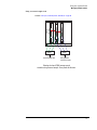
The following diagrams show typical multi-module configurations and the clock setups that apply
to each module:
33
Using the Agilent E1439
Managing multiple modules
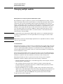
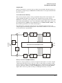
Managing multi-module systems
The
symbol indicates a 50 ohm terminator, which is required on unused SMB connectors in
systems using front panel distribution
Backplane
10 MHz
frequency
reference
Slot 0
Controller
1
Module #1 - “Front master,
phase locked to external
reference” on page 81
34
Module #1 - “Front master,
phase locked to external
reference” on page 81
10 MHz
frequency
reference
1
2
2
External reference and SYNC distribution
using VXI backplane ECL trigger lines.
Module #2 - “Front slave,
phase locked to master” on
page 81
Internal clock and SYNC distribution using
front panel SMB clock and SYNC
extender connections.
Backplane
1
2
Internal clock and SYNC distribution
using VXI backplane ECL trigger lines.
Module #1 - “Front master,
internal reference” on page
80
Module #2 - “Front slave,
phase locked to master” on
page 81
Slot 0
Controller
Module #2 - “Front slave,
phase locked to master” on
page 81
Module #2 - “Front slave,
phase locked to master” on
page 81
Slot 0
Controller
Module #1 - “Rear master,
internal reference” on page
82
Slot 0
Controller
Note
1
2
External reference and SYNC distribution using
front panel SMB clock and SYNC
extender connections.
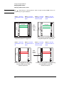
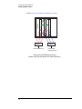
Using the Agilent E1439
Managing multiple modules
Module #2 - “Front master,
internal reference” on page
80
Module # 3 - “Front slave,
phase locked to master” on
page 81
Module #4 - “Front slave,
phase locked to master” on
page 81
Slot 0
Controller
Module #1 - “Front slave,
phase locked to master” on
page 81
1
2
3
4
Sharing clock and SYNC among several
modules via front panel distribution.
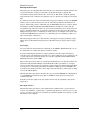
Managing multi-mainframe systems
Module #2 - “Front master,
Module #3 - “Front slave,
internal reference” on page 80 phase locked to master” on
page 81
Module #4 - “Front slave,
phase locked to master” on
page 81
Slot 0
Controller
Slot 0
Controller
Module #1 - “Front slave,
phase locked to master” on
page 81
1
2
3
4
VXI Mainframe A
VXI Mainframe B
Clock and SYNC distribution using front panel
extender connections within and between mainframes.
35
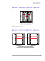
Using the Agilent E1439
Managing multiple modules
Module #1 - “Front slave,
phase locked to master” on
page 81
Module #2 - “Send sync to
slave” on page 84
Module # 3 - “Receive sync
from master” on page 85
Module #4 - “Front slave,
phase locked to master” on
page 81
Backplane
Slot 0
Controller
Slot 0
Controller
Backplane
1
2
3
VXI Mainframe A
VXI Mainframe B
Clock and SYNC distribution using front panel
extender connections between mainframes and
VXI backplane connections within mainframes.
36
4
Using the Agilent E1439
Managing multiple modules
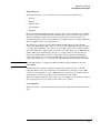
Using an external sample clock
Slot 0
Controller
All modules “Front sync, external sample clock, wired-OR sync” on page 83
Splitter
External sample clock
Splitter
User generated
external sync pulse
Sharing clock and SYNC among several
modules using external sample. Front panel distribution.
37
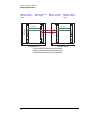
Using the Agilent E1439
Managing multiple modules
Slot 0
Controller
Backplane
All modules “Rear sync, external sample clock, wired-OR sync” on page 84
Splitter
External sample clock
Splitter
User generated
external sync pulse
Sharing clock and SYNC among several
modules using external sample. Rear panel distribution.
38
Using the Agilent E1439
Managing multiple modules
Synchronizing changes in multi-module systems
Multi-module systems require special treatment with respect to timing of frequency and filter
changes. Center frequency changes may involve synchronizing the local oscillators of all modules
in a system. Digital filter changes in multi-module systems require that the decimation counters
be synchronized.
Calling the following functions voids synchronized multi-module setups:
age1439_clock_setup and related low-level clock setup functions
age1439_clock_recover
age1439_input_autozero
age1439_input_range_auto
age1439_self_test
age1439_state_recall
Special considerations apply to the measurement loop. See “The measurement loop in multimodule systems” on page 24.
Synchronous digital filter changes
In multi-module systems where synchronous sampling is required, the decimation counters in all
the modules must be synchronous with each other. This condition can be forced by preparing each
module in the system in advance. Any measurement in progress is terminated at this time and the
module is placed in the Idle state. After each module is prepared, the next sync line transition
causes the digital decimation counter to be reset and started at the same time. Once this is done,
the decimation counters stay synchronized as long as the same ADC clock is used.
If you also intend to change the center frequency along with the digital filters, you should
synchronize the digital filters first. Otherwise, the center frequency phase becomes
unsynchronized when the digital filters are changed.
Synchronous center frequency changes
In multi-module systems you may prepare each module in advance of a frequency change, then
perform the change synchronously by asserting the Sync line. This preserves the phase
relationship of the local oscillators for all modules in the system. Certain special considerations
apply to multi-module frequency changes:
•
If all modules in a system are in the Idle state when the Sync line transition occurs, the LO
frequency is updated and the next measurement is armed.
•
If all modules are in the measurement state in continuous mode when the Sync line transition
occurs, the LO frequency is synchronously updated, and the measurement continues.
•
In continuous mode, care must be taken to assure that all modules are in the same state, either
the Idle state or the Measure state, before the Sync line transition occurs, otherwise some
modules re-arm while others continue the current measurement.
•
In block mode, it is simplest to keep Forced Idle asserted during the Sync line transitions to
keep all the modules in the Idle state.
•
If you also intend to change the digital filters along with the center frequency, you should
synchronize the digital filters first. Otherwise, the center frequency phase becomes nonsynchronized when the digital filters are changed.
39
Using the Agilent E1439
Managing multiple modules
Trigger and phase in multi-module systems
When you use triggering in multiple modules, you do not need to measure phase differences
between two or more channels if the channels are set up identically in terms of digital filtering and
LO frequency, and the digital filters and LOs are correctly synchronized. Since the filters and LOs
are synced together, their actual trigger delays and LO phases are identical and will cancel out of
relative phase measurements. Any remaining delay should be less than 10ns between two
modules in the same mainframe.
Only the module that generates the trigger has knowledge of the delay between the trigger event
and the start of data collection. Therefore, if you need the actual delay from the trigger, you
should use the trigger delay correction from the module that generated the trigger. Likewise, you
should obtain the LO phase at the time of the trigger from the module that generated the trigger.
See “Delay and phase in triggered measurements” on page 25.
External sample synchronization in multi-module systems
There are two general instances where you might want to use an external sample clock in a system
with multiple E1439s:
Note
•
You wish to have the ADC's sample at a rate other than the 95 MHz clock supplied with the
E1439.
•
You wish more precise simultaneous sampling than can be provided by the normal scheme
that uses the internal VCXOs within the modules locked together by a 2.5 MHz reference that
is distributed from module to module. By exercising care in matching the skew of the sample
clocks fed into each module, channel-to-channel group delays at low frequencies can be well
below a nanosecond.
External sample is specified only for use with baseband path.
To use external sample clocks with multiple modules and still perform synced measurements, you
need to use either the AGE1439_FRNT_SYNC_EXT_SAMP or AGE1439_REAR_SYNC_
EXT_SAMP clock setups (see “age1439_clock_setup” on page 78). These setups use the signal
that you feed into the Ext Clock/Ref BNC input of the E1439 as a sample clock for the ADC. A
counter within the E1439 generates two lower frequency clocks, one for the DSP circuitry and
one to clock the measurement SYNC signal between multiple modules. Since these clocks are
generated independently within each module, the counters in each module must be synced
together with a common externally generated signal in order to make properly synced and
triggered measurements involving multiple channels. You feed this "external sample sync" signal
into the External Trigger BNC and the module uses the signal to reset the counters to a known
phase.
The external sample sync signal should be generated on the falling edge of the external sample
clock, and fed into each module in the system by an identical length coax cable. Likewise, the
sample clock should be fed into each Ext Clock/Ref BNC by an identical length coax cable from a
common driver.
40
Using the Agilent E1439
Managing multiple modules
Here is the sequence of operations:
1. Put all modules into either the AGE1439_REAR_SYNC_EXT_SAMP mode or the
AGE1439_FRNT_SYNC_EXT_SAMP mode with the age1439_clock_setup command.
2. Issue the age1439_ext_sample_sync (AGE1439_EXT_SAMPLE_SYNC_ENABLE)
command to reset the counters within all the E1439s.
3. Generate the external sample sync pulse simultaneously into all modules. One way to do
this is to use one of the VXI TTLTRG lines and reclock the signal with the falling edge of
the sample clock. Note: If you are using an E1439A module with a serial number lower
than US41140000, you will need some user supplied hardware to convert TTLTRG to
ECL because older E1439As do not support TTL trigger.
4. Issue the age1439_clock_recover command to all modules since the DSP clock was
interrupted between the age1439_ext_sample_sync command and the external sync
signal on the Trigger input.
5. Sync the digital filters:
•
Force all modules to idle (age1439_meas_control).
•
Send the age1439_filter_sync command to all modules.
•
Assert and release the sync line from the master module (age1439_meas_control).
•
Release all modules from idle (age1439_meas_control).
6. Sync the digital local oscillators:
•
Force all modules to idle (age1439_meas_control).
•
Set all module frequencies to zero (age1439_frequency_center).
•
Assert and release system Sync (age1439_meas_control).
•
Set the LO frequencies to the desired ones (age1439_frequency_center).
•
Toggle system Sync again to synchronously set the LO frequencies (age1439_meas_
control).
•
Finally release all modules from idle (age1439_meas_control).
7. Now you may take a measurement:
•
Issue an age1439_meas_start.
•
Retrieve data from the modules when valid.
In the event that you do not supply a synchronizing signal in a reasonable length of time (or you
change your mind about it), the DSP clock can be restored by issuing age1439_ext_sample_sync
(AGE1439_EXT_SAMP_SYNC_CANCEL) followed by an age1439_clock_recover.
You should not need to perform the external sample sync operation again unless the external
clocks are interrupted or the clock setup changed.
See also the diagrams earlier in this section that show the physical setup. All the functions
mentioned above are described in “Functions listed alphabetically” in chapter 4.
41
Using the Agilent E1439
Transferring data
Transferring data
You can transfer data from the Agilent E1439C or D via the VMEbus. With the Agilent E1439D
you can also transfer data via the Local Bus and via a fiber optic interface.
•
The VMEbus is the universal data bus for VXI architecture. It provides flexibility and
versatility in transferring data. Transfers over the VMEbus are 16 bits or 32 bits wide.
•
The Local Bus on the Agilent E1439D supports faster transfer rates than the VMEbus. For
example, if you are transferring data from the Agilent E1439D to the Agilent E9821, the
Local Bus provides a direct pipeline to the Agilent E9821’s DSPs.
Using the Local Bus, you can transfer data in the background while processing data in a
signal-processing module. All Local Bus data transfers originate in the Agilent E1439D and
move towards a signal processing module to the right of the Agilent E1439D. If other
modules generate data to the left of the input module, the Agilent E1439D passes the data to
its right and inserts or appends its own data at the beginning or end of the frame.
•
42
The fiber optic interface, available on the Agilent E1439D, provides data rates greater than
200 Mbytes/second. It can transmit filtered or unfiltered data, copy data from its receiver to its
transmitter, or append data to copied data.
Using the Agilent E1439
Fiber Optic Interface
Fiber Optic Interface
The E1439D provides a fiber optic interface that can transmit continuous full bandwidth data
from the internal A/D converter. In addition, it can stream data from multiple synchronized
modules operating at lower bandwidths onto a single fiber optic channel. An optical receiver can
then simultaneously analyze data collected at different frequencies and bandwidths.
The E1439D fiber optic interface uses a serial data stream protocol providing high data
throughput and low latency characteristics. This protocol is intended to be compatible with the
Serial Front Panel Data Port Draft Standard (VITA 17.1, draft 0.5 dated February 26, 2001)
currently under development by the VITA Standards Organization (http://www.vita.com). VITA
17.1 is not yet approved and manufacturers are not yet permitted to claim conformance to the
draft standard. However, laboratory testing at Agilent Technologies has demonstrated
interoperability of the E1439D with fiber optic products from other manufacturers that also intend
to support the draft standard. These products include Systran Simplex Link Protocol products,
such as the SL100 and SL240, and Mercury Computer products, such as the RINOJ-F RACEway
I/O daughter card.
The following overview supplies the basic concepts required to use all the supported features. For
details, see the descriptions of the API functions.
43
Using the Agilent E1439
Fiber Optic Interface
Fiber Frames
Data is transmitted over the fiber interface in a series of fiber frames. Each fiber frame is
composed of a series of 32-bit values, which encode to 40 bits. Each 32-bit value can either be
data or an ordered set. Data and ordered sets are strung together to make the three types of fiber
frames—Data Frame, BOF, and EOE. The Data Frame transmits 0 to 512 32-bit data words. The
exact amount of data that is sent depends on the amount of data that is available when the fiber
interface is ready to send the Data Frame. BOF (Beginning Of Frame) is a synchronizing event
that can be sent just prior to the start of data transmission. EOE (End Of Epoch) is a synchronizing
event that contains the last 4 data bytes in an epoch. An epoch is composed of one or more Data
Frames followed by an EOE. The following shows the ordered sets and data that make up the
three fiber frames:
Data Frame (Normal Data Fiber Frame)
IDLE1
SOF2
0 to 512 data words3
CRC4
FEOF5
SEOF6
GO/STOP7
No data
CRC4
MEOF8
SEOF6
GO/STOP7
Last 4 data bytes in epoch10
CRC4
MEOF8
SEOF6
GO/STOP7
BOF (Sync Without Data Fiber Frame)
IDLE1
SOF2
EOE (Sync with Data Fiber Frame)
SWDV9
SOF2
1. Pad for Data Frame or BOF
2. Start Of Frame, framing event that embeds PIO1, PIO2, and DIR
3. 32 bit or 4 Byte words, maximum 2048 Bytes
4. Cyclic Redundancy Check, optional
5. Frame End Of Frame, end of Data Frame
6. Status End Of Frame, embeds FIFO OV and NRDY
7. Flow controls
8. Mark End Of Frame, end of BOF and EOE
9. Sync With Data Valid, start of EOE
10.4 bytes, exactly
Control Signals
PIO1, PIO2, DIR, and NRDY are FPDP (front panel data port) control signals. These signals can
be defined by another product or you can define their meaning and application.
When an overflow condition in the transmit FIFO occurs, the E1439D asserts FIFO OV indicating
a loss of data. This may occur in Append fiber mode if the available fiber bandwidth capability is
exceeded.
If flow control is enabled, the E1439D responds to the STOP and GO signals. See “Generate” on
page 48 for details.
44
Using the Agilent E1439
Fiber Optic Interface
Fiber Modes
The E1439D’s fiber interface can operate in five different modes:
•
“Off” on page 45
•
“Copy” on page 46
•
“Raw” on page 47
•
“Generate” on page 48
•
“Append” on page 50
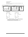
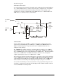
Off
The Off fiber mode disables the fiber transmitter but allows the fiber receiver to read control
signals. Normal data collection and filtering continues, and the data port selection determines
whether data is sent to the local bus (Agilent E1439D only) or read from the FIFO via the VME
bus. See the following illustration.
E1438D / E1439D
Fiber RX
ADC
Fiber TX
DIGITAL
FILTERS
FIFO
VME BUS
LBUS
Fiber Interface Setup
Note
Fiber Mode
Off
Rate
setting ignored
BOF
setting ignored
CRC
setting ignored
Flow Control
setting ignored
Epoch Generate
setting ignored
Epoch Size
setting ignored
Setting the data port to Fiber while in the Off fiber mode causes the data FIFO to fill up with
filtered ADC data, which then causes data collection to stop.
45
Using the Agilent E1439
Fiber Optic Interface
Copy
The Copy fiber mode copies optical data from its fiber receiver to its fiber transmitter without
adding any data. Normal data collection and filtering continues, and the data port selection
determines whether data is sent to the local bus (Agilent E1439D only) or read from the FIFO via
the VME bus. Copy is the default fiber mode after power-on or reset. See the following
illustration.
E1438D / E1439D
1 KB
FIFO
Fiber RX
ADC
DIGITAL
FILTERS
Fiber TX
FIFO
VME BUS
LBUS
Fiber Interface Setup
Note
Fiber Mode
Copy
Rate
106 or 250 MBs
BOF
setting ignored
CRC
must match incoming signal
Flow Control
setting ignored
Epoch Generate
setting ignored
Epoch Size
setting ignored
Setting the data port to Fiber while in the Copy fiber mode results in an invalid instrument state.
46
Using the Agilent E1439
Fiber Optic Interface
Raw
The Raw fiber mode transmits raw (i.e., unprocessed, full bandwidth) ADC data over the fiber
interface. At the same time that the raw data is transmitted over the fiber interface, filtered ADC
data can be sent over the local bus (Agilent E1439D only) or read from the FIFO via the VME
bus. After selecting Raw, optical data transmission starts at the trigger event and is not affected by
trigger delays or data delays. The raw data transmission continues even after the measurement is
complete. Changing the fiber mode stops data transmission. See the following illustration.
E1438D / E1439D
1 KB
FIFO
Fiber RX
ADC
DIGITAL
FILTERS
Fiber TX
FIFO
VME BUS
LBUS
Fiber Interface Setup
Fiber Mode
Raw
Rate
1061 or 250 MBs
BOF
Optional
CRC
ON2
Flow Control
Optional
Epoch Generate
Optional
Epoch Size
Divisible by 4
1. Only with external sample. Internal sample generates data too fast for
this rate.
2. Some receivers may
require CRC to be off
for compatibility
Note
Setting the data port to Fiber while in the Raw fiber mode results in an invalid instrument state
because raw and filtered data cannot both be sent over the fiber interface at the same time.
47
Using the Agilent E1439
Fiber Optic Interface
Generate
If flow control is off, Generate fiber mode transmits filtered ADC data over the fiber interface as
soon as data is available. ADC data is not available via any other data port and received optical
data is ignored. The following illustration shows an E1439D transmitting data when flow control
is turned off.
E1438D / E1439D
Fiber RX
Fiber TX
1 KB
FIFO
ADC
DIGITAL
FILTERS
FIFO
VME BUS
LBUS
Fiber Interface Setup
Fiber Mode
Generate
Rate
106 or 250 MBs
BOF
Optional
CRC
ON1
Flow Control
OFF
Epoch Generate
Optional
Epoch Size
Divisible by 4
1. Some receivers may
require CRC to be off
for compatibility
48
Using the Agilent E1439
Fiber Optic Interface
If flow control is on and the fiber receiver is capable of generating flow control signals, Generate
fiber mode transmits filtered ADC data after the fiber receiver indicates that it is ready and a
complete data block is ready to be transmitted. ADC data is not available via any other data port
and received optical data, other than the flow control signals, is ignored. The following
illustration shows an E1439D transmitting data to a fiber receiver when flow control is on.
E1438D / E1439D
Fiber Receiver
Fiber RX
Fiber TX
1 KB
FIFO
ADC
DIGITAL
FILTERS
Fiber
RX
DATA
Fiber
TX
FLOW
CONTROL
FIFO
VME BUS
Processing
LBUS
Fiber Interface Setup
Mode
Generate
Rate
106 or 250 MBs
BOF
Optional
CRC
ON
Flow Control
No Copy
Epoch Generate
Optional
Epoch Size
Divisible by 4
49
Using the Agilent E1439
Fiber Optic Interface
Append
The Append fiber mode copies optical data from its fiber receiver to its fiber transmitter and
appends its own filtered ADC data. This mode is required in an optical fiber append chain. For
the first module in an append chain, set the fiber mode to Generate, BOF to ON, and Epoch
Generate to ON. The module generates data epochs in the standard fashion and a BOF is sent after
each epoch. For all modules after the first, set fiber mode to Append, BOF to ON, and Epoch
Generate to ON. Each module copies received data to its transmitter output until a BOF is
received. The module then sends one epoch of filtered data from its ADC (if at least one block is
available), followed by a BOF.
In block data mode, the data from a single trigger is transmitted. Subsequent triggers should not
be generated faster than the data can be transmitted.
In continuous data mode, the generated data must not exceed the available fiber bandwidth,
allowing the data to be merged without data loss from a FIFO overrun. Therefore, you must
reduce the generated sample rate using either an external sample clock operating at a slower rate
or data decimation. If you use an external sample clock operating at a slower rate, epoch size must
be 1024 bytes (a larger epoch size causes a FIFO overrun resulting in a loss of data, and a smaller
epoch size increases overhead reducing the available bandwidth). The available bandwidth is then
about 101 MBytes/second or 238 MBytes/second. If you use data decimation, an epoch size of
approximately 2048 bytes provides the maximum available bandwidth.
Note
Epoch size and block size must be equal (in bytes). Since block size is in samples, you can
multiply block size by the number of bytes per sample to determine the equivalent epoch size.
Conversely, you can divide the epoch size by the number of bytes per sample to determine the
equivalent block size. Real 12-bit data contains 2 bytes per sample, complex 12-bit data and real
24-bit data contains 4 bytes per sample, and complex 24-bit data contains 8 bytes per sample.
50
Using the Agilent E1439
Fiber Optic Interface
The following shows two E1439D modules in an append chain transmitting data to a fiber
receiver when flow control is off.
E1438D / E1439D
E1438D / E1439D
Fiber RX
Fiber TX
1 KB
FIFO
Fiber RX
1 KB
FIFO
ADC
DIGITAL
FILTERS
Fiber Receiver
Fiber TX
Fiber
RX
1 KB
FIFO
FIFO
ADC
VME BUS
DIGITAL
FILTERS
Fiber
TX
DATA
FIFO
VME BUS
LBUS
Processing
LBUS
Fiber Interface Setup
First E1439D in chain
Next E1439D in chain
Mode
Generate
Mode
Append
Rate
106 or 250 MBs
Rate
same as module to left
BOF
ON
BOF
ON1
CRC
ON
CRC
ON
Flow Control
OFF
Flow Control
OFF
Epoch Generate
ON
Epoch Generate
ON
Epoch Size
Divisible by 4; must match blocksize
Epoch Size
Divisible by 4; must match blocksize
1. The final module in an append chain may require BOF to be Off for compatibility with data receivers that cannot process BOFs.
51
Using the Agilent E1439
Fiber Optic Interface
The following shows two E1439D modules in an append chain transmitting data to a fiber
receiver when flow control is on.
E1438D / E1439D
E1438D / E1439D
Fiber RX
Fiber TX
1 KB
FIFO
Fiber RX
1 KB
FIFO
ADC
DIGITAL
FILTERS
Fiber Receiver
Fiber TX
1 KB
FIFO
FIFO
ADC
VME BUS
DIGITAL
FILTERS
Fiber
RX
Fiber
TX
DATA
FIFO
VME BUS
LBUS
Processing
LBUS
Fiber Interface Setup
First E1439D in chain
Next E1439D in chain
Mode
Generate
Mode
Append
Rate
106 or 250 MBs
Rate
same as module to left
BOF
ON
BOF
ON1
CRC
ON
CRC
ON
Flow Control
Copy
Flow Control
No Copy2
Epoch Generate
ON
Epoch Generate
ON
Epoch Size
Divisible by 4; must match blocksize
Epoch Size
Divisible by 4; must match blocksize
1. The final module in an append chain may require BOF to be Off for compatibility with data receivers that cannot process BOFs.
2. Set intermediate modules to Copy and the last module to No Copy.
52
4
4
Agilent E1439 Programmer's Reference
Agilent E1439 Programmer's Reference
Introduction
Introduction
The programmer’s reference is presented as a set of VXIplug&play functions since this is the
primary targeted environment. However, when you performed the setup for the Agilent E1439,
drivers were installed to support various programming environments as described in
“Programming the Agilent E1439” in chapter 3.
The function descriptions in the programmer’s reference are valid for all environments. Be sure to
follow the instructions in “Getting Started and Introduction” in chapter 2 to assure proper
installation and to become familiar with the capabilities of your Agilent E1439 software in
various programming environments. You should find the example programs particularly helpful
for programming in various environments.
Many of the function descriptions in the programming reference include several related functions.
You may use the primary function to set all related parameters or you may use the other functions
within the group to set or query a single parameter.
Parameter variables are presented as alphanumeric values which are descriptive and easy to
remember. However, for faster programming you may use the numeric equivalents for the
parameter variables listed at the end of this section.
54
Agilent E1439 Programmer's Reference
Functions listed by class
Functions listed by class
Component
Capability
Subclass
INITIALIZE & CLOSE
Function Name
age1439_init (on page 132)
age1439_close (on page 86)
MEASURE
READ
INITIATE
age1439_meas_control (on page 151)
age1439_meas_init (on page 154)
age1439_meas_start (on page 155)
age1439_meas_status_get (on page 156)
age1439_wait (on page 189)
MEASURE
READ
FETCH
age1439_read (on page 159)
age1439_read64 (on page 159)
age1439_read_raw (on page 162)
MEASURE
CONFIGURE
age1439_clock_fs (on page 76)
age1439_clock_fs_get (on page 76)
age1439_clock_recover (on page 77)
age1439_clock_setup (on page 78)
age1439_clock_setup_get (on page 78)
age1439_combo_setup (on page 87)
age1439_data_memsize_get (on page 88)
age1439_data_scale_get (on page 89)
age1439_data_setup (on page 90)
age1439_ext_sample_sync (on page 104)
age1439_ext_sample_sync_get (on page 104)
age1439_filter_setup (on page 120)
age1439_frequency_setup (on page 128)
age1439_input_autozero (on page 134)
age1439_input_range_auto (on page 137)
age1439_input_setup (on page 141)
age1439_input_range_convert (on page 138)6
age1439_trigger_setup (on page 183)
MEASURE
CONFIGURE
LOW LEVEL
age1439_adc_clock (on page 72)
age1439_adc_clock_get (on page 72)
age1439_adc_divider (on page 73)
age1439_adc_divider_get (on page 73)
55
Agilent E1439 Programmer's Reference
Functions listed by class
Component
Capability
Subclass
Function Name
age1439_data_blocksize (on page 90)
age1439_data_blocksize_get (on page 90)
age1439_data_delay (on page 90)
age1439_data_delay_get (on page 90)
age1439_data_mode (on page 90)
age1439_data_mode_get (on page 90)
age1439_data_port (on page 90)
age1439_data_port_get (on page 90)
age1439_data_resolution (on page 90)
age1439_data_resolution_get (on page 90)
age1439_data_spectral_order (on page 90)
age1439_data_spectral_order_get (on page 90)
age1439_data_type (on page 90)
age1439_data_type_get (on page 90)
age1439_data_xfersize (on page 96)
age1439_data_xfersize_get (on page 96)
age1439_filter_bw (on page 120)
age1439_filter_bw_get (on page 120)
age1439_filter_decimate (on page 120)
age1439_filter_decimate_get (on page 120)
age1439_filter_sync (on page 123)
age1439_frequency_center (on page 128)
age1439_frequency_center_get (on page 128)
age1439_frequency_center_raw (on page 125)
age1439_frequency_center_raw_compute (on
page 127)
age1439_frequency_center_raw_get (on page 125)
age1439_frequency_cmplxdc (on page 128)
age1439_frequency_cmplxdc_get (on page 128)
age1439_frequency_sync (on page 128)
age1439_frequency_sync_get (on page 128)
age1439_front_panel_clock_input (on page 131)
age1439_front_panel_clock_input_get (on page 131)
age1439_input_alias_filter (on page 141)
age1439_input_alias_filter_get (on page 141)
age1439_input_autozero (on page 134)
age1439_input_coupling (on page 141)
age1439_input_coupling_get (on page 141)
age1439_input_offset (on page 135)
age1439_input_offset_get (on page 135)
56
Agilent E1439 Programmer's Reference
Functions listed by class
Component
Capability
Subclass
Function Name
age1439_input_offset_save (on page 136)
age1439_input_range (on page 141)
age1439_input_range_get (on page 141)
age1439_input_signal (on page 141)
age1439_input_signal_get (on page 141)
age1439_input_signal_path (on page 141)
age1439_input_signal_path_get (on page 141)
age1439_reference_clock (on page 165)
age1439_reference_clock_get (on page 165)
age1439_reference_prescaler (on page 166)
age1439_reference_prescaler_get (on page 166)
age1439_smb_clock_output (on page 173)
age1439_smb_clock_output_get (on page 173)
age1439_sync_clock (on page 178)
age1439_sync_clock_get (on page 178)
age1439_sync_direction (on page 179)
age1439_sync_direction_get (on page 179)
age1439_sync_output (on page 180)
age1439_sync_output_get (on page 180)
age1439_trigger_adclevel (on page 183)
age1439_trigger_adclevel_get (on page 183)
age1439_trigger_delay (on page 183)
age1439_trigger_delay_get (on page 183)
age1439_trigger_delay_actual_get (on page 181)
age1439_trigger_gen (on page 183)
age1439_trigger_gen_get (on page 183)
age1439_trigger_magdwell (on page 183)
age1439_trigger_magdwell_get (on page 183)
age1439_trigger_maglevel (on page 183)
age1439_trigger_maglevel_get (on page 183)
age1439_trigger_phase_actual_get (on page 182)
age1439_trigger_slope (on page 183)
age1439_trigger_slope_get (on page 183)
age1439_trigger_type (on page 183)
age1439_trigger_type_get (on page 183)
age1439_vcxo (on page 187)
age1439_vcxo_get (on page 187)
age1439_vxi_clock_output (on page 188)
age1439_vxi_clock_output_get (on page 188)
ROUTE
CONFIGURE
age1439_epoch_setup (on page 98)
57
Agilent E1439 Programmer's Reference
Functions listed by class
Component
Capability
Subclass
Function Name
age1439_fiber_setup (on page 112)
age1439_lbus_mode (on page 148)
age1439_lbus_mode_get (on page 148)
age1439_lbus_reset (on page 150)
age1439_lbus_reset_get (on page 150)
ROUTE
CONFIGURE
LOW LEVEL
age1439_fiber_BOF (on page 112)
age1439_fiber_BOF_get (on page 113)
age1439_fiber_crc (on page 113)
age1439_fiber_crc_get (on page 113)
age1439_fiber_flow_control (on page 114)
age1439_fiber_flow_control_get (on page 114)
age1439_fiber_mode (on page 113)
age1439_fiber_mode_get (on page 114)
age1439_fiber_transfer_rate (on page 114)
age1439_fiber_transfer_rate_get (on page 114)
age1439_epoch_generate (on page 98)
age1439_epoch_generate_get (on page 98)
age1439_header (on page 99)
age1439_epoch_header_get (on page 100)
age1439_epoch_header_enable (on page 99)
age1439_epoch_header_enable_get (on page 99)
age1439_epoch_size (on page 98)
age1439_epoch_size_get (on page 99)
ROUTE
CONTROL
age1439_fiber_clear (on page 106)
age1439_fiber_error_clear (on page 107)
age1439_fiber_LED_get (on page 110)
age1439_fiber_rcv_signals_get (on page 111)
age1439_fiber_signal_get (on page 115)
age1439_fiber_verify (on page 116)
age1439_fiber_xmt_BOF (on page 117)
age1439_fiber_xmt_signals (on page 118)
age1439_fiber_xmt_signals_get (on page 118)
UTILITY
age1439_attrib_get (on page 74)
age1439_cal_get (on page 75)
age1439_driver_debug_level (on page 97)
age1439_driver_debug_level_get (on page 97)
age1439_error_message (on page 102)
age1439_error_query (on page 103)
age1439_interrupt_mask_get (on page 146)
age1439_interrupt_priority_get (on page 146)
58
Agilent E1439 Programmer's Reference
Functions listed by class
Component
Capability
Subclass
Function Name
age1439_interrupt_restore (on page 145)
age1439_interrupt_setup (on page 146)
age1439_options_get (on page 157)
age1439_product_id_get (on page 158)
age1439_reset (on page 167)
age1439_reset_hard (on page 168)
age1439_revision_query (on page 169)
age1439_self_test (on page 170)
age1439_serial_number (on page 172)
age1439_serial_number_get (on page 172)
age1439_state_save (on page 175)
age1439_state_recall (on page 174)
age1439_status_get (on page 176)
59
Agilent E1439 Programmer's Reference
Functions listed by functional group
Functions listed by functional group
This section lists the programing functions in groups of related functions. A brief description of
each group follows:
“Initializing and closing” on page 61: You must initialize the I/O driver and set up each module
before using any other functions.
“Identification” on page 64: These functions identify the module, serial number and options.
“Analog setup” on page 61: These functions determine how the analog input section is
configured.
“Data format” on page 61: An Agilent E1439 can collect either real or complex data in 12-bit or
24-bit format. It can collect data into various blocksizes or in a continuous mode. This data can be
transferred either on the VXI backplane, the Local Bus or over the fiber interface.
“Digital processing” on page 62: The decimation filter provides bandpass filtering and decimation
capabilities. You may also select limited frequency spans away from baseband.
“Measurement control” on page 64: These functions initiate or terminate the measurement loop.
“Timing” on page 64: The clock signals for the ADC sample clock can be set in a variety of ways.
One Agilent E1439 can be enabled to drive the sample clock line on the VXI backplane or front
panel to enable synchronization of multiple Agilent E1439 modules.
“Trigger” on page 65: These functions set all parameters associated with triggering the beginning
of data collection.
“Synchronization (controlling multiple modules)” on page 66: These functions support
synchronous operation among multiple Agilent E1439s by using shared ADC clock and Sync
signals to drive all the modules in a system.
“Reading data” on page 65: The Agilent E1439 reads data from either the VME or the Local Bus
data port. This data can optionally be scaled and converted to floating point.
“Interrupts” on page 64: The Agilent E1439 can be programmed to interrupt via the VXI
backplane whenever certain status conditions are present.
“Debugging” on page 62: Allows you to identify program and hardware problems.
“Fiber Interface” on page 62: These functions are only available on E1439D.
60
Agilent E1439 Programmer's Reference
Functions listed by functional group
Initializing and closing
age1439_init (on page 132) −initializes the I/O driver for a module
age1439_close (on page 86) −closes the module's software connection
Analog setup
age1439_input_setup (on page 141) −sets all the analog input parameters
age1439_input_alias_filter (on page 141) −include/bypass the built-in analog anti-alias filter
age1439_input_alias_filter_get (on page 141) −gets the anti-alias filter state
age1439_input_autozero (on page 141) −nulls out the input dc offset in baseband mode
age1439_input_coupling (on page 141) −selects ac or dc input coupling
age1439_input_coupling_get (on page 141) −get the input coupling type
age1439_input_offset (on page 135) −sets the dc offset settings for the current range
age1439_input_offset_get (on page 135) −gets the dc offset settings
age1439_input_offset_save (on page 136) −saves the dc offset settings in NVRAM
age1439_input_range (on page 141) −sets the full scale input range
age1439_input_range_auto (on page 137) −performs auto-ranging
age1439_input_range_convert (on page 138) −converts input range to volts
age1439_input_range_get (on page 141) −gets the input range
age1439_input_signal_path (on page 141) −selects baseband or IF signal path
age1439_input_signal_path_get (on page 141) −gets the signal path state
age1439_input_signal (on page 141) −connect/disconnect the input signal to the input amplifier
age1439_input_signal_get (on page 141) −gets the input buffer amplifier state
age1439_state_save (on page 175) −saves the current module state
age1439_state_recall (on page 174) −recalls a previous module state
Data format
age1439_data_setup (on page 90) −sets all format and data output flow parameters
age1439_data_blocksize (on page 90) −determines the size of the output data block
age1439_data_blocksize_get (on page 90) −gets the output data block size
age1439_data_delay (on page 90) −determines FIFO delay in continuous mode
age1439_data_delay_get (on page 90) −gets FIFO delay
age1439_data_memsize_get (on page 88) −returns module's memory size
age1439_data_mode (on page 90) −selects block mode or continuous mode
age1439_data_mode_get (on page 90) −gets the data mode
age1439_data_port (on page 90) −selects VME bus, local bus or fiber interface for output
transmission
age1439_data_port_get (on page 90) −gets the output port designation
age1439_data_resolution (on page 90) −selects 12 or 24 bits data resolution
age1439_data_resolution_get (on page 90) −gets the data resolution
age1439_data_scale_get (on page 89) −gets the data scale factor used to convert raw data to
volts
age1439_data_type (on page 90) −selects real or complex output data
age1439_data_type_get (on page 90) −gets output data type
age1439_data_spectral_order −specifies the spectral order of the output data.
age1439_data_spectral_order_get −gets the spectral order of the output data.
age1439_data_xfersize (on page 96) −allows a specified amount of data to be read before an
entire block has been acquired.
age1439_data_xfersize_get (on page 96) −gets the data transfer size
61
Agilent E1439 Programmer's Reference
Functions listed by functional group
age1439_lbus_mode (on page 148) −sets the transmission mode of the local bus
age1439_lbus_mode_get (on page 148) −gets the local bus transmission mode
age1439_lbus_reset (on page 150) −resets the local bus
age1439_lbus_reset_get (on page 150) −gets the local bus reset state
Debugging
age1439_cal_get (on page 75) −gets last calibration date of specified board
age1439_clock_recover (on page 77) −allows recovery from an out-of-spec external sample
clock
age1439_driver_debug_level (on page 97) −sets the debug level
age1439_driver_debug_level_get (on page 97) −gets the debug level
age1439_error_message (on page 102) −returns error information obtained from function
calls
age1439_error_query (on page 103) −queries the module for the most recent error
age1439_status_get (on page 176) −retrieves the module's status register information
age1439_meas_status_get (on page 156) - retrieves the current measurement status register
information
age1439_self_test (on page 170) −performs a self-test on the module and returns the result
Digital processing
age1439_combo_setup (on page 87) −a quick way to set blocksize, center frequency, and signal bandwidth with one function
age1439_filter_setup (on page 120) −sets the digital filter bandwidth and decimation filter
parameters
age1439_filter_bw (on page 120) −selects a signal filter bandwidth
age1439_filter_bw_get (on page 120) −gets the signal filter bandwidth
age1439_filter_decimate (on page 120) −enables/disables an extra factor of 2 decimation
age1439_filter_decimate_get (on page 120) −gets current state of extra decimation
age1439_filter_sync (on page 123) −synchronizes the decimation filter counter
age1439_frequency_setup (on page 128) −sets all zoom center frequency parameters
age1439_frequency_center (on page 128) −sets the center frequency
age1439_frequency_center_get (on page 128) −gets the current center frequency
age1439_frequency_center_raw (on page 125) −quickly sets the center frequency
age1439_frequency_center_raw_compute (on page 127) −quickly calculates the values for
age1439_frequency_center_raw
age1439_frequency_center_raw_get (on page 125) −gets the raw center frequency
age1439_frequency_cmplxdc (on page 128) −selects a complex baseband measurement
age1439_frequency_cmplxdc_get (on page 128) −gets the state of the baseband measurement
mode
age1439_frequency_sync (on page 128) −prepares the module for a synchronous frequency
change
age1439_frequency_sync_get (on page 128) −gets the state of the synchronous change mode
Fiber Interface
age1439_fiber_BOF (on page 112) −controls whether or not automatically generated
BOF events are transmitted
age1439_fiber_BOF_get (on page 112) −returns the current value of bofEnable
age1439_fiber_clear (on page 106) −clears all data from the fiber interface FIFO buffers
age1439_fiber_crc (on page 112) sets up the fiber interface to transmit and receive cyclic
62
Agilent E1439 Programmer's Reference
Functions listed by functional group
redundancy checks.
age1439_fiber_crc_get (on page 112) −returns the current status of the cyclic redundancy
check setting.
age1439_fiber_error_clear (on page 107)−clears fiber errors from the status register
age1439_fiber_error_get (on page 108) −returns the value of the fiber interface error register.
age1439_fiber_flow_control (on page 112) −configures fiber flow control, enabling or
disabling transmitter flow control signals.
age1439_fiber_flow_control_get (on page 112) −returns the current status of the fiber
flow control function.
age1439_fiber_LED_get (on page 110) −returns a data register indicating the state of the
front panel XMT/RCV led’s.
age1439_fiber_mode (on page 112) −selects the fiber interface mode.
age1439_fiber_mode_get (on page 112) −gets the current mode of the fiber interface.
age1439_fiber_rcv_signals_get (on page 111) −displays the current value of PIO1, PIO2,
DIR and NRDY bits from the fiber receiver.
age1439_fiber_setup (on page 112) −sets the parameters associated with the fiber interface.
age1439_fiber_signal_get (on page 115) −returns a value indicating whether or not an
optical signal is detected by the optical fiber interface receiver.
age1439_fiber_transfer_rate (on page 112) −selects the transfer rate for fiber optic data.
age1439_fiber_transfer_rate_get (on page 112) −gets the current selection of transfer
rate for fiber optic data.
age1439_fiber_verify (on page 116) −proforms a verification of the fiber interface using
either an internal of external signal path.
age1439_fiber_xmt_BOF (on page 117) −sends a BOF event used for synchronization
with other fiber interfaces before data acquisition begins.
age1439_fiber_xmt_signals (on page 118) −sets the transmitted values of any PIO1,
PIO2, DIR or, NRDY FPDP control signals on the fiber transmitter
age1439_fiber_xmt_signals_get (on page 118) −displays the current value of PIO1,
PIO2, DIR and NRDY bits from the fiber transmitter.
age1439_epoch_generate (on page 98) −controls whether or not data epochs are generated.
age1439_epoch_generate_get (on page 98) − gets the current value of epochGenerate
age1439_epoch_header (on page 98) −sets the value of the first 32 bits of the epoch
header. It can be used by the optical receiver to direct where to route and/or how to
process associated epoch data.
age1439_epoch_header_get (on page 98) − returns the header value and the value of the
increment count for the epoch header.
age1439_epoch_header_enable (on page 98) −controls whether or not epoch headers are
generated
age1439_epoch_header_enable_get (on page 98) −returns the current value of header
enable.
age1439_epoch_setup (on page 98) −sets the parameters relevant to the transmission of
data epochs on the fiber interface.
age1439_epoch_size (on page 98) −sets the size of data epochs in bytes.
age1439_epoch_size_get (on page 98) −returns the current size of data epochs on the fiber
interface
63
Agilent E1439 Programmer's Reference
Functions listed by functional group
Identification
age1439_product_id_get (on page 158) −returns the module’s product identification string
age1439_options_get (on page 157) −returns the module’s options
age1439_serial_number (on page 157) −sets the module’s serial number for product repair
purposes
age1439_serial_number_get (on page 157) −returns the module’s serial number
age1439_revision_query (on page 169) −returns strings that identify the date of the module’s
firmware revision
Interrupts
age1439_attrib_get (on page 74) −gets low-level attributes of current I/O library session
age1439_interrupt_setup (on page 146) −sets all interrupt parameters
age1439_interrupt_mask_get (on page 146) −gets the interrupt event mask
age1439_interrupt_priority_get (on page 146) −gets the VME interrupt line
age1439_interrupt_restore (on page 145) −restores the interrupt masks to the most recent setting
Measurement control
age1439_meas_control (on page 151) −initiates and controls measurements in multi-module
systems
age1439_meas_init (on page 154) −initiates a measurement without first checking for valid
hardware setup
age1439_meas_start (on page 155) −checks for valid hardware setup and then initiates a measurement
age1439_reset (on page 167) −places the module in a known state
age1439_reset_hard (on page 168) −resets the module hardware
Timing
age1439_clock_setup (on page 78) −sets all timing parameters for commonly used measurement setups
age1439_clock_setup_get (on page 78) −gets the current clock setup
age1439_clock_fs (on page 76) −provides the frequency of an external sample clock
age1439_clock_fs_get (on page 76) −gets the current external sample clock frequency
age1439_adc_clock (on page 72) −specifies the ADC clock source
age1439_adc_clock_get (on page 72) −gets the ADC clock source
age1439_adc_divider (on page 73) −determines which divider is applied to the ADC clock
source
age1439_adc_divider_get (on page 73)−gets the module's current clock divider state
age1439_ext_sample_sync (on page 104) −enables and disables external sample sync
age1439_ext_sample_sync_get (on page 104) −gets the state of external sample sync
age1439_front_panel_clock_input (on page 131) −specifies the source for the front panel
clock
age1439_front_panel_clock_input_get (on page 131) −gets the front panel clock source
age1439_reference_clock (on page 165) −selects the source of the reference clock
age1439_reference_clock_get (on page 165) −gets the source of the reference clock
age1439_reference_prescaler (on page 166) −selects prescaling of the reference clock
age1439_reference_prescaler_get (on page 166) −gets prescaling of the reference clock
age1439_smb_clock_output (on page 173) −specifies which clock to output from the SMB
64
Agilent E1439 Programmer's Reference
Functions listed by functional group
clock connectors
age1439_smb_clock_output_get (on page 173) −gets which clock to output from the SMB
clock connectors
age1439_sync_clock (on page 178) −selects the source of the sync signal
age1439_sync_clock_get (on page 178) −gets the source of the sync signal
age1439_sync_direction (on page 179) −selects front or rear panel availability of the sync signal
age1439_sync_direction_get (on page 179) −gets the state of front or rear panel clock availability
age1439_sync_output (on page 180) −selects the output for the sync signal
age1439_sync_output_get (on page 180) −gets the output for the sync signal
age1439_vcxo (on page 187) −selects whether the module should use an internal clock source
age1439_vcxo_get (on page 187) −gets whether the internal clock source is on or off
age1439_vxi_clock_output (on page 188) −selects which clock drives the VXI clock
age1439_vxi_clock_output_get (on page 188) −gets which clock drives the VXI clock
Trigger
age1439_trigger_setup (on page 183) −sets all parameters associated with triggering the
beginning of data collection
age1439_trigger_adclevel (on page 183) −specifies the threshold for the ADC trigger
age1439_trigger_adclevel_get (on page 183) −gets the trigger threshold
age1439_trigger_delay (on page 183) −specifies a pre- or post-trigger delay time
age1439_trigger_delay_get (on page 183) −gets the trigger delay time
age1439_trigger_delay_actual_get (on page 181) −gets the actual delay time from the most
recent trigger event
age1439_trigger_gen (on page 183) −determines whether a module can generate a trigger
age1439_trigger_gen_get (on page 183) −gets the trigger generation status
age1439_trigger_magdwell (on page 183) −specifies the dwell time (in samples) before a
magnitude trigger.
age1439_trigger_magdwell_get (on page 183) −gets the magnitude trigger dwell time.
age1439_trigger_maglevel (on page 183) −specifies the threshold for a magnitude trigger
age1439_trigger_maglevel_get (on page 183) −gets magnitude trigger threshold
age1439_trigger_phase_actual_get (on page 182) −returns a representation of the phase
value of the LO at the most recent trigger point
age1439_trigger_slope (on page 183) −selects a positive or negative trigger
age1439_trigger_slope_get (on page 183) −gets trigger slope
age1439_trigger_type (on page 183) −specifies the trigger type
age1439_trigger_type_get (on page 183) −gets trigger type
Reading data
age1439_data_scale_get (on page 89) −gets data scale factor
age1439_read (on page 159) −reads scaled 32-bit float data from FIFO
age1439_read64 (on page 159) −reads scaled 64-bit float data from FIFO, specifically for
VEE applications
age1439_read_raw (on page 162) −reads raw data from FIFO
65
Agilent E1439 Programmer's Reference
Functions listed by functional group
Synchronization (controlling multiple modules)
age1439_clock_setup (on page 78) −supplies commonly used clock and sync configurations
See “Timing” on page 64 for low level clock and sync setup commands
age1439_clock_setup_get (on page 78) −gets the current clock and sync setup
age1439_clock_fs (on page 76) −provides a clock frequency for external sample clock configurations
age1439_clock_fs_get (on page 76) −gets the external clock frequency
age1439_filter_sync (on page 123) −synchronizes the decimation filter counter
age1439_frequency_sync and age1439_frequency_center (on page 128) −prepare the modules for frequency change
age1439_meas_control (on page 151) −synchronizes arming and triggering in multi-module
systems
age1439_trigger_gen (on page 183) −determines whether a module can generate a trigger
age1439_trigger_gen_get (on page 183) −gets the trigger generation status
age1439_wait (on page 189) −facilitates the synchronization and control of multi-module systems
66
Agilent E1439 Programmer's Reference
Functions listed alphabetically
Functions listed alphabetically
age1439_adc_clock (on page 72) −determines the ADC clock source
age1439_adc_clock_get (on page 72) −gets the ADC clock source
age1439_adc_divider (on page 73) −determines which divider is applied to the ADC
clock source
age1439_adc_divider_get (on page 73)−gets the module's current clock divider state
age1439_attrib_get (on page 74) −gets low-level attributes of current I/O library session.
age1439_cal_get (on page 75) −gets last calibration date of specified board
age1439_clock_fs (on page 76) −provides the module with the frequency of an external
sample clock
age1439_clock_fs_get (on page 76) −gets the current external sample clock frequency
age1439_clock_recover (on page 77) −allows recovery from an out-of-spec external sample clock
age1439_clock_setup (on page 78) −sets all timing parameters for commonly used measurement setups
age1439_clock_setup_get (on page 78) −gets the current clock setup
age1439_close (on page 86) −closes the module's software connection
age1439_combo_setup (on page 87) −a quick way to set blocksize, center frequency, and
signal bandwidth with one function
age1439_data_blocksize (on page 90) −determines the size of the output data block
age1439_data_blocksize_get (on page 90) −gets the output data block size
age1439_data_delay (on page 90) −determines FIFO delay in continuous mode
age1439_data_delay_get (on page 90) −gets FIFO delay in continuous mode
age1439_data_memsize_get (on page 88) −returns module's memory size in megabytes
age1439_data_mode (on page 90) −selects block mode or continuous mode
age1439_data_mode_get (on page 90) −gets the data mode
age1439_data_port (on page 90) −selects VME bus, local bus or fiber interface for
output port transmission
age1439_data_port_get (on page 90) −gets the output port designation
age1439_data_resolution (on page 90) −selects 12 or 24 bits data resolution
age1439_data_resolution_get (on page 90) −gets the data resolution
age1439_data_scale_get (on page 89) −gets data scale factor used to convert raw data to
volts
age1439_data_setup (on page 90) −sets all format and data output flow parameters
age1439_data_spectral_order (on page 90) −specifies the spectral order of the output
data.
age1439_data_spectral_order_get (on page 90) −gets the spectral order of the output
data.
age1439_data_type (on page 90) −selects real or complex output data
age1439_data_type_get (on page 90) −gets output data type
age1439_data_xfersize (on page 96) −allows a specified amount of data to be read before
an entire block has been acquired
age1439_data_xfersize_get (on page 96) −gets the data transfer size
age1439_driver_debug_level (on page 97) −sets the debug level
67
Agilent E1439 Programmer's Reference
Functions listed alphabetically
age1439_driver_debug_level_get (on page 97) −gets the debug level
age1439_epoch_generate (on page 98) −controls whether or not data epochs are generated.
age1439_epoch_generate_get (on page 98) − gets the current value of epochGenerate
age1439_epoch_header (on page 98) −sets the value of the first 32 bits of the epoch
header. It can be used by the optical receiver to direct where to route and/or how to
process associated epoch data.
age1439_epoch_header_get (on page 98) − returns the header value and the value of the
increment count for the epoch header.
age1439_epoch_header_enable (on page 98) −controls whether or not epoch headers are
generated
age1439_epoch_header_enable_get (on page 98) −returns the current value of header
enable.
age1439_epoch_setup (on page 98) −sets the parameters relevant to the transmission of
data epochs on the fiber interface.
age1439_epoch_size (on page 98) −sets the size of data epochs in bytes.
age1439_epoch_size_get (on page 98) −returns the current size of data epochs.
age1439_error_message (on page 102) −returns error information obtained from function
calls.
age1439_error_query (on page 103) −queries the module for the most recent error.
age1439_ext_sample_sync (on page 104) −enables and disables sync to an external sample clock
age1439_ext_sample_sync_get (on page 104) −gets the state of external sample sync
age1439_fiber_BOF (on page 112) −controls whether or not automatically generated
BOF events are transmitted
age1439_fiber_BOF_get (on page 112) −returns the current value of bofEnable
age1439_fiber_clear (on page 106) −clears all data from the fiber interface FIFO buffers
age1439_fiber_crc (on page 112) sets up the fiber interface to transmit and receive cyclic
redundancy checks.
age1439_fiber_crc_get (on page 112) −returns the current status of the cyclic redundancy
check setting.
age1439_fiber_error_clear (on page 107) −clears fiber errors from the status register
age1439_fiber_error_get (on page 108) −returns the value of the fiber interface error register.
age1439_fiber_flow_control (on page 112) −configures fiber flow control, enabling or
disabling transmitter flow control signals.
age1439_fiber_LED_get (on page 110) −returns a data register indicating the state of the
front panel XMT/RCV led’s.
age1439_fiber_mode (on page 112) −selects the fiber interface mode.
age1439_fiber_mode_get (on page 112) −gets the current mode of the fiber interface.
age1439_fiber_rcv_signal_get (on page 111) −displays the current value of PIO1, PIO2,
DIR and NRDY bits on the fiber receiver.
age1439_fiber_signal_get (on page 115) −returns a value indicating whether or not an
optical signal is detected by the optical fiber interface receiver.
age1439_fiber_setup (on page 112) −sets the parameters associated with the fiber interface.
age1439_fiber_transfer_rate (on page 112) −selects the transfer rate for fiber optic data.
age1439_fiber_transfer_rate_get (on page 112) −gets the current selection of transfer
rate for fiber optic data.
age1439_fiber_verify (on page 116) −preforms a verification of the fiber interface using
either an internal of external signal path.
age1439_fiber_xmt_BOF (on page 117) −sends a BOF event used for synchronization
68
Agilent E1439 Programmer's Reference
Functions listed alphabetically
with other fiber interfaces before data acquisition begins.
age1439_fiber_xmt_signals (on page 118) −sets the transmitted values of any PIO1,
PIO2, DIR or, NRDY FPDP control signals on the fiber transmitter.
age1439_fiber_xmt_signals_get (on page 118) −displays the current value of PIO1,
PIO2, DIR and NRDY bits on the fiber transmitter.
age1439_filter_bw (on page 120) −selects a signal filter bandwidth
age1439_filter_bw_get (on page 120) −gets the signal filter bandwidth
age1439_filter_decimate (on page 120) −enables/disables and extra factor of 2 decimation
age1439_filter_decimate_get (on page 120) −gets current state of extra decimation
age1439_filter_setup (on page 120) −sets the digital filter bandwidth and decimation filter parameters
age1439_filter_sync (on page 123) −synchronizes the decimation filter counter
age1439_frequency_center (on page 128) −sets the center frequency
age1439_frequency_center_get (on page 128) −gets the current center frequency
age1439_frequency_center_raw (on page 125) −quickly sets the center frequency
age1439_frequency_center_raw_compute (on page 127) −quickly calculates the values
for age1439_frequency_center_raw
age1439_frequency_center_raw_get (on page 125) −gets the raw center frequency
age1439_frequency_cmplxdc (on page 128) −selects a complex baseband measurement
age1439_frequency_cmplxdc_get (on page 128) −gets the state of the baseband measurement mode
age1439_frequency_setup (on page 128) −sets all the zoom center frequency parameters
age1439_frequency_sync (on page 128) −prepares the module for a synchronous frequency change
age1439_frequency_sync_get (on page 128) −gets the state of the synchronous change
mode
age1439_front_panel_clock_input (on page 131) −specifies the source of the front panel
clock
age1439_front_panel_clock_input_get (on page 131) −gets the front panel clock source
age1439_init (on page 132) −initializes the I/O driver for a module
age1439_input_alias_filter (on page 141) −include/bypass the built-in analog anti-alias
filter
age1439_input_alias_filter_get (on page 141) −gets the anti-alias filter state
age1439_input_autozero (on page 134) −nulls out the input dc offset in baseband mode
age1439_input_coupling (on page 141) −selects ac or dc input coupling
age1439_input_coupling_get (on page 141) −get the input coupling type
age1439_input_offset (on page 135) −sets the dc offset settings for the current range
age1439_input_offset_get (on page 135) −gets the dc offset settings
age1439_input_offset_save (on page 136) −saves the dc offset settings in NVRAM
age1439_input_range (on page 141) −sets the full scale range
age1439_input_range_auto (on page 137) −performs auto-ranging in baseband mode
age1439_input_range_convert (on page 138) −converts the input range to volts
age1439_input_range_get (on page 141) −gets the input range
age1439_input_setup (on page 141) −sets all the analog input parameters
age1439_input_signal (on page 141) −connect/disconnect the input signal to the input
amplifiers
age1439_input_signal_get (on page 141) −gets the input buffer amplifier state
age1439_input_signal_path (on page 141) −selects baseband or IF signal path
age1439_input_signal_path_get (on page 141) −gets the signal path state
age1439_interrupt_mask_get (on page 146) −gets the interrupt event mask
age1439_interrupt_priority_get (on page 146) −gets the VME interrupt line
69
Agilent E1439 Programmer's Reference
Functions listed alphabetically
age1439_interrupt_restore (on page 145) −restores the interrupt masks to the most recent
setting
age1439_interrupt_setup (on page 146) −sets both interrupt parameters
age1439_lbus_mode (on page 148) −sets the local bus transmission mode
age1439_lbus_mode_get (on page 148) −gets the local bus mode
age1439_lbus_reset (on page 150) −resets local bus
age1439_lbus_reset_get (on page 150) −gets the local bus mode reset state
age1439_meas_control (on page 151) −initiates and controls measurements in multimodule systems
age1439_meas_init (on page 154) −initiates a measurement without first checking for
valid hardware setup
age1439_meas_start (on page 155) −checks for valid hardware setup and then initiates a
measurement
age1439_meas_status_get (on page 156) −returns the current measurement status.
age1439_options_get (on page 157) −returns the module’s options
age1439_product_id_get (on page 158) −returns the module’s product identification
string
age1439_read (on page 159) −reads scaled 32-bit float data from FIFO
age1439_read_raw (on page 162) −reads raw data from FIFO
age1439_read64 (on page 159) −reads scaled 64-bit float data from FIFO, specifically for
VEE applications
age1439_reference_clock (on page 165) −selects the source of the reference clock
age1439_reference_clock_get (on page 165) −gets the source of the reference clock
age1439_reference_prescaler (on page 166) −selects prescaling of the reference clock
age1439_reference_prescaler_get (on page 166) −gets prescaling of the reference clock
age1439_reset (on page 167) −places the module in a known state
age1439_reset_hard (on page 168) −resets the module hardware
age1439_revision_query (on page 169) −returns strings that identify the date of the firmware revision.
age1439_self_test (on page 170) −performs a self-test on the module and returns the result
age1439_serial_number (on page 157) −sets the module’s serial number for product
repair purposes
age1439_serial_number_get (on page 157) −returns the module’s serial number
age1439_smb_clock_output (on page 173) −specifies which clock to output from the
SMB clock connectors
age1439_smb_clock_output_get (on page 173) −gets which clock to output from the
SMB clock connectors
age1439_state_save (on page 175) −saves the current module state
age1439_state_recall (on page 174) −recalls a saved module state
age1439_status_get (on page 176) −retrieves module's status register information
age1439_sync_clock (on page 178) −selects the source of the sync signal
age1439_sync_clock_get (on page 178) −gets the source of the sync signal
age1439_sync_direction (on page 179) −selects front or rear panel availability of the sync
signal
age1439_sync_direction_get (on page 179) −gets the state of front or rear panel clock
availability
age1439_sync_output (on page 180) −selects the output for the sync signal
age1439_sync_output_get (on page 180) −gets the output for the sync signal
age1439_trigger_adclevel (on page 183) −specifies the threshold for the ADC trigger
age1439_trigger_adclevel_get (on page 183) −gets the trigger threshold
age1439_trigger_delay (on page 183) −specifies a pre- or post-trigger delay time
age1439_trigger_delay_actual_get (on page 181) −gets the actual delay time from the
70
Agilent E1439 Programmer's Reference
Functions listed alphabetically
most recent trigger event
age1439_trigger_delay_get (on page 183) −gets the trigger delay time
age1439_trigger_gen (on page 183) −determines whether a module can generate a trigger
age1439_trigger_gen_get (on page 183) −gets the trigger generation status
age1439_trigger_magdwell (on page 183) −specifies the dwell time (in samples) before a
magnitude trigger
age1439_trigger_magdwell_get (on page 183) −gets the magnitude trigger dwell time in
samples
age1439_trigger_maglevel (on page 183) −specifies the threshold for a magnitude trigger
age1439_trigger_maglevel_get (on page 183) −gets magnitude trigger threshold
age1439_trigger_phase_actual_get (on page 182) −returns a representation of the phase
value of the LO at the most recent trigger point
age1439_trigger_setup (on page 183) −sets all parameters associated with triggering the
beginning of data collection
age1439_trigger_slope (on page 183) −selects a positive or negative trigger
age1439_trigger_slope_get (on page 183) −gets trigger slope
age1439_trigger_type (on page 183) −determines the trigger type
age1439_trigger_type_get (on page 183) −gets trigger type
age1439_vcxo (on page 187) −selects whether the module should use an internal clock
source
age1439_vcxo_get (on page 187) −gets whether the internal clock source is on or off
age1439_vxi_clock_output (on page 188) −selects which clock drives the VXI clock
age1439_vxi_clock_output_get (on page 188) −gets which clock drives the VXI clock
age1439_wait (on page 189) −facilitates the synchronization and control of multi-module
systems
71
Agilent E1439 Programmer's Reference
Functions listed alphabetically
age1439_adc_clock
Specifies the ADC clock source. This description also includes the query function:
age1439_adc_clock_get
VXIplug&play Syntax
#include "age1439".h
ViStatus age1439_adc_clock(ViSession id, ViInt16 adcClock);
ViStatus age1439_adc_clock_get(ViSession id, ViPInt16 adcClockPtr);
Note
This command should be used only for specialized custom clock requirements. Most useful clock
setups can be supplied by age1439_clock_setup.
Parameters
id
is the VXI instrument session pointer returned by the age1439_init function.
adcClock
AGE1439_VCXO_INTERNAL selects an internal oscillator within the module. age1439_vcxo_
freq determines which oscillator is used. age1439_vcxo determines whether the internal
oscillator is turned on. You must use all three of the functions to provide the desired internal clock
source.
AGE1439_VCXO_EXT_REF takes an external reference signal on the front panel and uses a
phase-locked loop to convert it to the ADC clock of the module. The ADC clock can be either 100
MHz or 102.4 MHz. The external reference used by the phase lock loop to synthesize the ADC
clock can be either a 10 MHz or 10.24 MHz signal.
AGE1439_EXT_SAMPLE_CLOCK uses an external sample clock selected by age1439_
reference_clock.
adcClockPtr
points to the value of the current adcClock.
Return Value
AGE1439_SUCCESS indicates that a function was successful.
Values other than AGE1439_SUCCESS indicate an error condition or other important status
condition. To determine the error message, pass the return value to “age1439_error_message” on
page 102.
See Also
“Commands which halt active measurements” on page 198, “Default values” on page 201,
“age1439_init” on page 132, “age1439_clock_setup” on page 78, “age1439_vcxo” on page 187,
“age1439_front_panel_clock_input” on page 131, “age1439_reference_clock” on page 165,
“Using clock and sync” in chapter 3
72
Agilent E1439 Programmer's Reference
Functions listed alphabetically
age1439_adc_divider
Determines which divider is applied to the ADC clock source. This description also includes the
query function:
age1439_adc_divider_get
VXIplug&play Syntax
#include "age1439".h
ViStatus age1439_adc_divider(ViSession id, ViInt16 adcDivider);
ViStatus age1439_adc_divider_get(ViSession id, ViPInt16 adcDividerPtr);
Note
This command should be used only for specialized custom clock requirements. Most useful clock
setups can be supplied by age1439_clock_setup.
Description
This function should generally be left in the default mode. The alternate mode applies to a
different model of the module.
Parameters
id
is the VXI instrument session pointer returned by the age1439_init function.
adcDivider
AGE1439_DIVIDE_BY_10 divides the ADC clock by 10.
AGE1439_DIVIDE_BY_38 divides the ADC clock by 38.
adcDividerPtr
points to the current value of adcDivider.
Return Value
AGE1439_SUCCESS indicates that a function was successful.
Values other than AGE1439_SUCCESS indicate an error condition or other important status
condition. To determine the error message, pass the return value to “age1439_error_message” on
page 102.
Comments
The Agilent E1439 normally runs its sample clock at 95 MHz. It divides that clock by 38 to
generate 2.5 MHz, which can be compared against a user-supplied 10Mhz reference that we
internally divide by 4 (age1439_reference_prescaler) which also generates a 2.5 MHz clock. In
the case of a multi module system without an external reference clock, the master module sends
its 2.5 MHz clock out on the VXI bus or front panel smbs for use by the other module's PLLs.
See Also
“Default values” on page 201, “age1439_init” on page 132, “age1439_clock_setup” on page 78,
“Using clock and sync” in chapter 3
73
Agilent E1439 Programmer's Reference
Functions listed alphabetically
age1439_attrib_get
Gets low-level attributes of current I/O library session.
VXIplug&play Syntax
#include "age1439".h
ViStatus age1439_attrib_get(ViSession id, ViInt16 attribute, ViPint32 value);
Description
age1439_attrib_get is used primarily to manage the use of interrupts which requires making
direct VISA function calls. Since interrupts are a shared resource across all modules using the
VXI interface, it is not possible for the Agilent E1439 library, which governs single modules, to
provide the functions to properly manage interrupts.
This function is used to access either the I/O library handle or the mapped I/O base address of the
module. You should refer to the appropriate VISA documentation for descriptions of the I/O
library functions.
Parameters
id
is the VXI instrument session pointer returned by the age1439_init function.
attribute
designates the type of attribute to return.
AGE1439_IO_HANDLE accesses the I/O library handle.
AGE1439_IO_ADDRESS points to the mapped I/O base address of the module.
AGE1439_RM_HANDLE accesses the I/O library handle of the default resource manager.
AGE1439_DATA_REGISTER points to the mapped address of the Agilent E1439 data register.
One or both of these parameters are used when calling I/O library functions directly.
value
is the value of the requested attribute. For the VISA I/O library the value of the handle attribute
corresponds to the vi parameter used by the majority of the I/O functions. The address attribute
points to the base of the mapped I/O address space.
Example
See the interrupt.c example program.
Return Value
AGE1439_SUCCESS indicates that a function was successful.
Values other than AGE1439_SUCCESS indicate an error condition or other important status
condition. To determine the error message, pass the return value to “age1439_error_message” on
page 102.
See Also
“age1439_init” on page 132, “age1439_interrupt_setup” on page 146
74
Agilent E1439 Programmer's Reference
Functions listed alphabetically
age1439_cal_get
Gets last calibration date of specified board.
VXIplug&play Syntax
#include "age1439".h
ViStatus age1439_cal_get(ViSession id, ViInt16 board, ViPInt32 datestampPtr);
Description
age1439_cal_get is used to read the date stamp of the last calibration.
Parameters
id
is the VXI instrument session pointer returned by the age1439_init function.
board
AGE1439_01_BOARD returns calibration information for the 01 (digital/ADC) board.
AGE1439_03_BOARD returns calibration information for the 03 (input) board.
datestampPtr
points to the return location for the timestamp of the most recent saved calibrations. Format is
YYYYMMDD in base 10 notation.
Return Value
AGE1439_SUCCESS indicates that a function was successful.
Values other than AGE1439_SUCCESS indicate an error condition or other important status
condition. To determine the error message, pass the return value to “age1439_error_message” on
page 102.
See Also
“age1439_init” on page 132
75
Agilent E1439 Programmer's Reference
Functions listed alphabetically
age1439_clock_fs
Provides the module with the frequency of an external sample clock. This description also
includes the query:
age1439_clock_fs_get
VXIplug&play Syntax
#include "age1439".h
ViStatus age1439_clock_fs(ViSession id, ViReal64 fs);
ViStatus age1439_clock_fs_get(ViSession id, ViPReal64 fsPtr);
Description
This command is applicable only when an external sample clock is used. It is an order-dependent
command and must be set after selecting the external sample clock.
When using an external sample clock or when a module is a non-master in a multi-module group,
the frequency of the ADC clock is unknown by the module. It is the responsibility of the
programmer to provide the correct frequency so that library functions dependent on fs operate
properly. This value has no effect if the module is not set up to use the external sample clock.
Parameters
id
is the VXI instrument session pointer returned by the age1439_init function.
fs
provides the module with the frequency of an external sample clock (from 10,000,000 to
103,000,000) connected to the Ext Clk TTL connector.
AGE1439_FS_MIN supplies the minimum external sample clock frequency.
AGE1439_FS_MAX supplies the maximum external sample clock frequency.
fsPtr
points to the current value of the external sample clock frequency. If the Agilent E1439 is set to
the internal ADC clock, this query returns the value of that clock frequency. If the Agilent E1439
is set to the external clock, this query returns the last value entered via the age1439_clock_fs
function.
Return Value
AGE1439_SUCCESS indicates that a function was successful.
Values other than AGE1439_SUCCESS indicate an error condition or other important status
condition. To determine the error message, pass the return value to “age1439_error_message” on
page 102.
See Also
“Default values” on page 201, “age1439_init” on page 132, “age1439_clock_setup” on page 78,
“age1439_front_panel_clock_input” on page 131, “age1439_ext_sample_sync” on page 104,
“Using clock and sync” in chapter 3
76
Agilent E1439 Programmer's Reference
Functions listed alphabetically
age1439_clock_recover
Allows recovery from an out-of-spec external sample clock.
VXIplug&play Syntax
#include "age1439".h
ViStatus age1439_clock_recover(ViSession id);
Description
This command is used to restore proper function if the module has received an out-of spec
external sample clock. An out-of-spec situation could occur if the external sample clock is
removed or changed during operation, or if it has glitches which don’t meet specs. In this case the
module would cease functioning and this command must be issued in order to resume proper
operation after restoring a valid clock.
Parameters
id
Return Value
AGE1439_SUCCESS indicates that a function was successful.
Values other than AGE1439_SUCCESS indicate an error condition or other important status
condition. To determine the error message, pass the return value to “age1439_error_message” on
page 102.
See Also
“Commands which halt active measurements” on page 198, “age1439_init” on page 132,
“age1439_ext_sample_sync” on page 104, “age1439_clock_setup” on page 78
77
Agilent E1439 Programmer's Reference
Functions listed alphabetically
age1439_clock_setup
Sets all timing parameters for commonly used measurement setups. This description also includes
a query:
age1439_clock_setup_get
VXIplug&play Syntax
#include "age1439".h
ViStatus age1439_clock_setup(ViSession id, ViInt16 clockSetup);
ViStatus age1439_clock_setup_get(ViSession id, ViPInt16 clockSetupPtr);
Description
age1439_clock_setup is used to select the source and distribution of clocking and
synchronization signals used by the Agilent E1439 module. The primary clock signal used by the
module is the ADC clock, for which the rising edges indicate the time for each sample of the
analog-to-digital converter.
This function changes the settings controlled by the following lower-level functions:
age1439_adc_clock
age1439_adc_divider
age1439_front_panel_clock_input
age1439_reference_clock
age1439_reference_prescaler
age1439_smb_clock_output
age1439_sync_clock
age1439_sync_direction
age1439_sync_output
age1439_vcxo
Note
Setups using the external sample clock require that you use age1439_clock_fs to supply the clock
frequency.
Parameters
id
is the VXI instrument session pointer returned by the age1439_init function.
clockSetup
This parameter provides a quick way to set up most of the timing parameters for several standard
clock configurations. The following setups are available:
78
Agilent E1439 Programmer's Reference
Functions listed alphabetically
Simple clock setups for stand-alone modules
Internal reference
AGE1439_SIMPLE_INT_REF
ADC_CLK
VCXO_INTERNAL
VCXO
VCXO_ON
ADC_DIVIDER
DIVIDE_BY_38
REFERENCE_PRESCALER
PRESCALE_BY_1
VXI_CLK_OUTPUT
CLOCK_OFF
REFERENCE_CLOCK
N/A
FRONT_PANEL_CLOCK
CLOCK_OFF
SMB_CLOCK_OUTPUT
CLOCK_OFF
SYNC_CLOCK
DIVIDED_ADC_CLOCK
SYNC_OUTPUT
SYNC_OUT_OFF
SYNC_DIRECTION
N/A
Phase locked to external reference
AGE1439_SIMPLE_EXT_REF
ADC_CLK
VCXO_EXT_REF
VCXO
VCXO_ON
ADC_DIVIDER
DIVIDE_BY_38
REFERENCE_PRESCALER
PRESCALE_BY_4
VXI_CLK_OUTPUT
CLOCK_OFF
REFERENCE_CLOCK
FRONT_PANEL_CLOCK
FRONT_PANEL_CLOCK
BNC_CLOCK
SMB_CLOCK_OUTPUT
CLOCK_OFF
SYNC_CLOCK
DIVIDED_ADC_CLOCK
SYNC_OUTPUT
SYNC_OUT_OFF
SYNC_DIRECTION
N/A
79
Agilent E1439 Programmer's Reference
Functions listed alphabetically
External sample clock (for use with baseband path only)
AGE1439_SIMPLE_EXT_SAMP
ADC_CLK
EXT_SAMPLE_CLOCK
VCXO
VCXO_OFF
ADC_DIVIDER
DIVIDE_BY_38
REFERENCE_PRESCALER
PRESCALE_BY_1
VXI_CLK_OUTPUT
CLOCK_OFF
REFERENCE_CLOCK
FRONT_PANEL_CLOCK
FRONT_PANEL_CLOCK
BNC_CLOCK
SMB_CLOCK_OUTPUT
CLOCK_OFF
SYNC_CLOCK
DIVIDED_ADC_CLOCK
SYNC_OUTPUT
SYNC_OUT_OFF
SYNC_DIRECTION
N/A
Front panel master-slave setups, one master per mainframe
Front master, internal reference
AGE1439_FRNT_MSTR_INT_REF
80
ADC_CLK
VCXO_INTERNAL
VCXO
VCXO_ON
ADC_DIVIDER
DIVIDE_BY_38
REFERENCE_PRESCALER
PRESCALE_BY_1
VXI_CLK_OUTPUT
CLOCK_OFF
REFERENCE_CLOCK
N/A
FRONT_PANEL_CLOCK
CLOCK_OFF
SMB_CLOCK_OUTPUT
DIVIDED_ADC_CLOCK
SYNC_CLOCK
DIVIDED_ADC_CLOCK
SYNC_OUTPUT
SYNC_OUT_SMB
SYNC_DIRECTION
FRNT_TO_REAR
Agilent E1439 Programmer's Reference
Functions listed alphabetically
Front master, phase locked to external reference
AGE1439_FRNT_REAR_MSTR_EXT_REF
ADC_CLK
VCXO_EXT_REF
VCXO
VCXO_ON
ADC_DIVIDER
DIVIDE_BY_38
REFERENCE_PRESCALER
PRESCALE_BY_4
VXI_CLK_OUTPUT
CLOCK_OFF
REFERENCE_CLOCK
FRONT_PANEL_CLOCK
FRONT_PANEL_CLOCK
BNC_CLOCK
SMB_CLOCK_OUTPUT
DIVIDED_ADC_CLOCK
SYNC_CLOCK
DIVIDED_ADC_CLOCK
SYNC_OUTPUT
SYNC_OUT_SMB
SYNC_DIRECTION
FRNT_TO_REAR
Front slave, phase locked to master
AGE1439_FRNT_REAR_SLAV_EXT_REF
ADC_CLK
VCXO_EXT_REF
VCXO
VCXO_ON
ADC_DIVIDER
DIVIDE_BY_38
REFERENCE_PRESCALER
PRESCALE_BY_1
VXI_CLK_OUTPUT
CLOCK_OFF
REFERENCE_CLOCK
FRONT_PANEL_CLOCK
FRONT_PANEL_CLOCK
SMB_CLK
SMB_CLOCK_OUTPUT
CLOCK_OFF
SYNC_CLOCK
SMB_CLOCK
SYNC_OUTPUT
SYNC_OUT_SMB
SYNC_DIRECTION
FRNT_TO_REAR
81
Agilent E1439 Programmer's Reference
Functions listed alphabetically
Rear panel master-slave setups, one master per mainframe
Rear master, internal reference
AGE1439_REAR_MSTR_INT_REF
ADC_CLK
VCXO_INTERNAL
VCXO
VCXO_ON
ADC_DIVIDER
DIVIDE_BY_38
REFERENCE_PRESCALER
PRESCALE_BY_1
VXI_CLK_OUTPUT
DIVIDED_ADC_CLOCK
REFERENCE_CLOCK
N/A
FRONT_PANEL_CLOCK
CLOCK_OFF
SMB_CLOCK_OUTPUT
CLOCK_OFF
SYNC_CLOCK
DIVIDED_ADC_CLOCK
SYNC_OUTPUT
SYNC_OUT_VXI
SYNC_DIRECTION
REAR_TO_FRNT
Rear master, phase locked to external reference
AGE1439_REAR_MSTR_EXT_REF
82
ADC_CLK
VCXO_EXT_REF
VCXO
VCXO_ON
ADC_DIVIDER
DIVIDE_BY_38
REFERENCE_PRESCALER
PRESCALE_BY_4
VXI_CLK_OUTPUT
DIVIDED_ADC_CLOCK
REFERENCE_CLOCK
FRONT_PANEL_CLOCK
FRONT_PANEL_CLOCK
BNC_CLOCK
SMB_CLOCK_OUTPUT
CLOCK_OFF
SYNC_CLOCK
DIVIDED_ADC_CLOCK
SYNC_OUTPUT
SYNC_OUT_VXI
SYNC_DIRECTION
REAR_TO_FRNT
Agilent E1439 Programmer's Reference
Functions listed alphabetically
Rear slave, phase locked to master
AGE1439_REAR_SLAV_EXT_REF
ADC_CLK
VCXO_EXT_REF
VCXO
VCXO_ON
ADC_DIVIDER
DIVIDE_BY_38
REFERENCE_PRESCALER
PRESCALE_BY_1
VXI_CLK_OUTPUT
CLOCK_OFF
REFERENCE_CLOCK
VXI_CLOCK
FRONT_PANEL_CLOCK
CLOCK_OFF
SMB_CLOCK_OUTPUT
CLOCK_OFF
SYNC_CLOCK
VXI_CLOCK
SYNC_OUTPUT
SYNC_OUT_VXI
SYNC_DIRECTION
REAR_TO_FRNT
Multi-module external sample setups, set all modules the same
Front sync, external sample clock, wired-OR sync
AGE1439_FRNT_SYNC_EXT_SAMP
ADC_CLK
EXT_SAMPLE_CLOCK
VCXO
VCXO_OFF
ADC_DIVIDER
DIVIDE_BY_38
REFERENCE_PRESCALER
PRESCALE_BY_1
VXI_CLK_OUTPUT
CLOCK_OFF
REFERENCE_CLOCK
FRONT_PANEL_CLOCK
FRONT_PANEL_CLOCK
BNC_CLOCK
SMB_CLOCK_OUTPUT
CLOCK_OFF
SYNC_CLOCK
DIVIDED_ADC_CLOCK
SYNC_OUTPUT
SYNC_OUT_SMB
SYNC_DIRECTION
FRNT_TO_REAR
83
Agilent E1439 Programmer's Reference
Functions listed alphabetically
Rear sync, external sample clock, wired-OR sync
AGE1439_REAR_SYNC_EXT_SAMP
ADC_CLK
EXT_SAMPLE_CLOCK
VCXO
VCXO_OFF
ADC_DIVIDER
DIVIDE_BY_38
REFERENCE_PRESCALER
PRESCALE_BY_1
VXI_CLK_OUTPUT
CLOCK_OFF
REFERENCE_CLOCK
FRONT_PANEL_CLOCK
FRONT_PANEL_CLOCK
BNC_CLOCK
SMB_CLOCK_OUTPUT
CLOCK_OFF
SYNC_CLOCK
DIVIDED_ADC_CLOCK
SYNC_OUTPUT
SYNC_OUT_VXI
SYNC_DIRECTION
REAR_TO_FRNT
Multiple mainframe setups
Send sync to slave
AGE1439_FRNT_MSTR_INT_REF
84
ADC_CLK
VCXO_INTERNAL
VCXO
VCXO_ON
ADC_DIVIDER
DIVIDE_BY_38
REFERENCE_PRESCALER
PRESCALE_BY_1
VXI_CLK_OUTPUT
DIVIDED_ADC_CLOCK
REFERENCE_CLOCK
N/A
FRONT_PANEL_CLOCK
CLOCK_OFF
SMB_CLOCK_OUTPUT
DIVIDED_ADC_CLOCK
SYNC_CLOCK
VXI_CLOCK
SYNC_OUTPUT
SYNC_OUT_BOTH
SYNC_DIRECTION
REAR_TO_FRONT
Agilent E1439 Programmer's Reference
Functions listed alphabetically
Receive sync from master
AGE1439_FRNT_REAR_SLAV_EXT_REF
clockSetupPtr
ADC_CLK
VCXO_EXT_REF
VCXO
VCXO_ON
ADC_DIVIDER
DIVIDE_BY_38
REFERENCE_PRESCALER
PRESCALE_BY_1
VXI_CLK_OUTPUT
FRONT_PANEL_CLOCK
REFERENCE_CLOCK
FRONT_PANEL_CLOCK
FRONT_PANEL_CLOCK
SMB_CLOCK
SMB_CLOCK_OUTPUT
CLOCK_OFF
SYNC_CLOCK
SMB_CLOCK
SYNC_OUTPUT
SYNC_OUT_BOTH
SYNC_DIRECTION
FRONT_TO_REAR
points to the current value of clockSetup.
AGE1439_CUSTOM_CLOCK_SETUP is returned from age1439_clock_setup_get when lowlevel clock configuration functions are used to set up clocks to a non-standard configuration.
Example
The program multichan.exe example program provides an example of how to correctly set up a
multi-module system with synchronous clocks.
Return Value
AGE1439_SUCCESS indicates that a function was successful.
Values other than AGE1439_SUCCESS indicate an error condition or other important status
condition. To determine the error message, pass the return value to “age1439_error_message” on
page 102.
Effect on Active Measurement
age1439_clock_setup aborts any measurement in progress.
See Also
“Commands which halt active measurements” on page 198, “Default values” on page 201,
“age1439_init” on page 132, “age1439_clock_fs” on page 76, “age1439_clock_recover” on
page 77, “age1439_ext_sample_sync” on page 104, “Using clock and sync” in chapter 3,
“Managing multiple modules” in chapter 3
85
Agilent E1439 Programmer's Reference
Functions listed alphabetically
age1439_close
Closes the module's software connection.
VXIplug&play Syntax
#include "age1439".h
ViStatus age1439_close(ViSession id);
Description
age1439_close terminates the software connection to the module, deallocates system resources,
and places the module in the Idle state. After this function has been executed the specified id
identifier is no longer a valid parameter for function calls.
Parameters
id
is the VXI instrument session pointer returned by the age1439_init function.
Return Value
AGE1439_SUCCESS indicates that a function was successful.
Values other than AGE1439_SUCCESS indicate an error condition or other important status
condition. To determine the error message, pass the return value to “age1439_error_message” on
page 102.
See Also
“age1439_init” on page 132
86
Agilent E1439 Programmer's Reference
Functions listed alphabetically
age1439_combo_setup
Combines often used setup commands from various functions.
age1439_combo_setup sets signal bandwidth, blocksize and center frequency.
VXIplug&play Syntax
#include "age1439".h
ViStatus age1439_combo_setup(ViSession id, ViInt16 sigBw, ViInt32 blocksize, ViInt32
phase, ViInt32 interpolate);
Description
age1439_combo_setup provides a faster way to set up parameters from several functions which
are often used together.
Parameters
id
is the VXI instrument session pointer returned by the age1439_init function.
blocksize
See “age1439_data_setup” on page 90 for a description of the blocksize parameter.
interpolate
See “age1439_frequency_center_raw” on page 125 for a description of the interpolate parameter.
phase
See “age1439_frequency_center_raw” on page 125 for a description of the phase parameter.
sigBw
See “age1439_filter_setup” on page 120 for a description of the sigBw parameter.
Comments
This command halts the current measurement which also releases the forced Idle state. If you use
this command in multi-module systems to synchronously change the center frequency while the
modules are forced to Idle, then you should subsquently call age1439_meas_control to re-assert
the forced Idle condition.
Return Value
AGE1439_SUCCESS indicates that a function was successful.
Values other than AGE1439_SUCCESS indicate an error condition or other important status
condition. To determine the error message, pass the return value to “age1439_error_message” on
page 102.
See Also
“Commands which halt active measurements” on page 198, “age1439_init” on page 132,
“age1439_filter_setup” on page 120, “age1439_frequency_center_raw” on page 125, “age1439_
data_setup” on page 90, “age1439_meas_control” on page 151
87
Agilent E1439 Programmer's Reference
Functions listed alphabetically
age1439_data_memsize_get
Returns the module's memory size in megabytes.
VXIplug&play Syntax
#include "age1439".h
ViStatus age1439_data_memsize_get(ViSession id, ViPInt16 memSizePtr);
Description
This command allows you to determine whether your module contains standard memory of 18
Mbytes or a larger memory option.
Parameters
id
is the VXI instrument session pointer returned by the age1439_init function.
memSizePtr
points to the memory size in number of Megabytes.
Return Value
AGE1439_SUCCESS indicates that a function was successful.
Values other than AGE1439_SUCCESS indicate an error condition or other important status
condition. To determine the error message, pass the return value to “age1439_error_message” on
page 102.
See Also
“age1439_init” on page 132, “age1439_data_setup” on page 90.
88
Agilent E1439 Programmer's Reference
Functions listed alphabetically
age1439_data_scale_get
Gets the data scale factor.
VXIplug&play Syntax
#include "age1439".h
ViStatus age1439_data_scale_get(ViSession id, ViPReal64 scalePtr);
Description
age1439_data_scale_get calculates the correct scale factor for raw data using the current data
resolution and input range. The factor returned by this function is used to multiply raw data to get
data in volts.
When the module is providing only the real part of complex data, the data is doubled to provide
consistent spectrum measurements. This occurs with either shift decimation or when the real part
of a zoomed signal with a non-zero center frequency is taken.
Parameters
id
is the VXI instrument session pointer returned by the age1439_init function.
scalePtr
points to the calculated scale factor with which to scale raw data to volts.
Return Value
AGE1439_SUCCESS indicates that a function was successful.
Values other than AGE1439_SUCCESS indicate an error condition or other important status
condition. To determine the error message, pass the return value to “age1439_error_message” on
page 102.
See Also
“age1439_init” on page 132, “age1439_data_setup” on page 90, “age1439_read_raw” on
page 162, “age1439_input_range_auto” on page 137, “age1439_filter_setup” on page 120
89
Agilent E1439 Programmer's Reference
Functions listed alphabetically
age1439_data_setup
Sets all format and data output flow parameters. This description also includes information on the
following functions which set or query the format and flow parameters individually:
age1439_data_blocksize determines the size of the output data block.
age1439_data_blocksize_get gets the output data block size.
age1439_data_delay determines the FIFO delay in continuous mode.
age1439_data_delay_get gets the FIFO delay in continuous mode.
age1439_data_mode selects block mode or continuous mode.
age1439_data_mode_get gets the data mode.
age1439_data_port selects VME bus or local bus output port.
age1439_data_port_get gets the output port designation.
age1439_data_resolution selects 12 or 24 bits data resolution.
age1439_data_resolution_get gets the data resolution.
age1439_data_spectral_order specifies the spectral order of the output data.
age1439_data_spectral_order_get gets the spectral order of the output data.
age1439_data_type selects real or complex output data.
age1439_data_type_get gets output data type.
VXIplug&play Syntax
#include "age1439".h
ViStatus age1439_data_setup(ViSession id, ViInt16 dataType, ViInt16 resolution, ViInt16
mode, ViInt32 blocksize, ViInt32 dataDelay, ViInt16 spectralOrder, ViInt16 port);
ViStatus age1439_data_blocksize(ViSession id, ViInt32 blocksize);
ViStatus age1439_data_blocksize_get(ViSession id, ViPint32 blocksizePtr);
ViStatus age1439_data_delay(ViSession id, ViInt32 dataDelay);
ViStatus age1439_data_delay_get(ViSession id, ViPInt32 dataDelayPtr);
ViStatus age1439_data_mode(ViSession id, ViInt16 mode);
ViStatus age1439_data_mode_get(ViSession id, ViPInt16 modePtr);
ViStatus age1439_data_port(ViSession id, ViInt16 port);
ViStatus age1439_data_port_get(ViSession id, ViPInt16 portPtr);
ViStatus age1439_data_resolution(ViSession id, ViInt16 resolution);
ViStatus age1439_data_resolution_get(ViSession id, ViPInt16 resolutionPtr);
ViStatus age1439_data_spectral_order(ViSession id, ViInt16 spectralOrder);
ViStatus age1439_data_spectral_order_get(ViSession id, ViPInt16 spectralOrderPtr);
ViStatus age1439_data_type(ViSession id, ViInt16 dataType);
ViStatus age1439_data_type_get(ViSession id, ViPInt16 dataTypePtr);
Description
Note
The functions, age1439_data_delay, age1439_data_mode, age1439_data_resolution, and
age1439_data_type work the same for the fiber interface as they do for the other interfaces.
Parameters
id
is the VXI instrument session pointer returned by the age1439_init function.
blocksize
determines the number of sample points in each output data block.
AGE1439_BLOCKSIZE_MIN selects the minimum blocksize.
90
Agilent E1439 Programmer's Reference
Functions listed alphabetically
AGE1439_BLOCKSIZE_MAX selects the maximum blocksize.
AGE1439_BLOCKSIZE_DEF sets the default blocksize.
The range of available block sizes depends on the number of bytes required for each sample. The
command accepts any number between 2 and memory size (in bytes) × 2/3. If the requested block
size falls outside the range shown in the table the previous valid value is used and a status register
flag (bit 6) is set indicating a setup error. The blocksize is updated after the setup is changed to be
valid.
For real data blocksize is the number of real data values per data block. For complex data
blocksize is the number of complex data pairs per data block.
The following table summarizes the available block sizes for each setting of the dataType, and
resolution parameters.
resolution
min. block size
max block size
in Msamples
(2 M*72 memory)1
real
12
6
12
real
24
3
6
complex
12
3
6
complex
24
2
3
data type
1. Parity memory is used in non-parity mode, so 2M× 72
bit memory yields 18 Mbytes of FIFO storage.
Note
Block size must be an even number. Considerably more samples may need to be taken in order to
set the block available status bit.
blocksizePtr
points to the current value of the blocksize parameter. The returned value is the closest valid value
to the requested block size.
dataDelay
is used to specify the minimum FIFO delay in number of samples. This parameter applies only in
continuous mode.
AGE1439_DATA_DELAY_MAXsets the maximum allowable delay.
AGE1439_DATA_DELAY_MIN sets the minimum allowable delay.
dataDelayPtr
points to the current value of the delay parameter.
dataType
determines whether the Agilent E1439 collects and returns real or complex data.
Setting this parameter to AGE1439_REAL causes only the real part of the data to be returned for
each sample
AGE1439_COMPLEX causes the real data followed by the imaginary data to be returned in each
sample.
Normally, if the center frequency set with the age1439_frequency_setup function is zero, the
type should be set to AGE1439_REAL since the imaginary component of each sample is zero
anyway. When non-zero center frequencies are used the type should normally be set to
AGE1439_COMPLEX, otherwise the imaginary component of the signal is lost.
91
Agilent E1439 Programmer's Reference
Functions listed alphabetically
when dataType is set to AGE1439_REAL and there is a non-zero center frequency the data scale
value is doubled for consistent spectrum measurements
dataTypePtr
points to the current value of the dataType parameter.
mode
selects whether the Agilent E1439's data collection operates in block mode or continuous mode.
AGE1439_BLOCK selects block transfer mode in which the measurement is halted after each
block of data. To start collection of the next data block the module must be armed and triggered
again. This mode is used whenever each block of data is to be associated with an individual
trigger event.
AGE1439_CONTINUOUS means that a single arm and trigger event starts a measurement which
runs continuously with no gaps between output data blocks. The measurement continues as long
as the data is read out fast enough to prevent overflow in the output FIFO. The continuous mode is
useful for continuous signal processing applications where data gaps are unacceptable.
modePtr
points to the current value of the mode parameter.
port
determines which output port is used to take data from the Agilent E1439 module.
Setting port to AGE1439_VME means the data is to be output using standard VME register reads.
This is the instrument default.
Setting port to AGE1439_LBUS means the data is to be output as a byte-serial data stream via the
VXI local bus (Agilent E1439D only) . When using the local bus port the module immediately to
the right of the Agilent E1439 must be capable of receiving the local bus byte sequence.
Setting port to AGE1439_FIBER means the filtered ADC data is to be transmitted as a serial data
stream over the fiber interface.
portPtr
points to the current value of the port parameter.
resolution
selects data resolution of either 12 or 24 bits by using resolution values of AGE1439_12BIT or
AGE1439_24BIT respectively. Choosing 12-bit precision allows for more samples in the FIFO
memory. Choosing 24 bits allows more dynamic range. Because of the broadband white noise
present on the input of the analog-to-digital converter, it is normally sufficient to use 12 bit
resolution whenever the age1439_filter_setup function specifies a signal bandwidth greater than
10 MHz. For narrower bandwidths much of the broadband white noise is filtered out, resulting in
lower noise in the output data. To take advantage of this lower noise, you should use the 24-bit
data resolution.
resolutionPtr
points to the current value of the resolution parameter.
Comments
The following table summarizes the output word or byte sequence for each combination of
dataType, resolution, and port parameters:
92
Agilent E1439 Programmer's Reference
Functions listed alphabetically
data type
data
resolution
port
transfer
width
xfers1
real
12 bit
VME
16 bit
1
R0[11:0] |Z4
R1[11:0] |Z4 ...
complex
12 bit
VME
16 bit
2
R0[11:0] |Z4
Q0[11:0] |Z4
R1[11:0] |Z4
Q1[11:0] |Z4 ...
real
24 bit
VME
16 bit
2
R0[23:8]
R0[7:0] |Z8
R1[23:8]
R1[7:0] |Z8 ...
complex
24 bit
VME
16 bit
4
R0[23:8]
R0[7:0] |Z8
Q0[23:8]
Q0[7:0] |Z8
R1[23:8]
R1[7:0] |Z8 ...
real
12 bit
LBUS
8 bit
2
R0[11:4]
R0[3:0] |Z4
R1[11:4]
R1[3:0] |Z4 ...
complex
12 bit
LBUS
8 bit
4
R0[11:4]
R0[3:0] |Z4
Q0[11:4]
Q0[3:0] |Z4
R1[11:4]
R1[3:0] |Z4 ...
real
24 bit
LBUS
8 bit
4
R0[23:16]
R0[15:8]
R0[7:0]
Z8
R1[23:16]
R1[15:8] ...
complex
24 bit
LBUS
8 bit
8
R0[23:16]
R0[15:8],
R0[7:0]
Z8,
Q0[23:16]
Q0[15:8]
Q0[7:0]
Z8
R1[23:16]
R1[15:8] ...
sequence2
93
Agilent E1439 Programmer's Reference
Functions listed alphabetically
data type
data
resolution
port
transfer
width
xfers1
real
12 bit
Fiber
32 bit
1/2
R0[11:0] |Z4|R1[11:0] |Z4
R2[11:0] |Z4|R3[11:0] |Z4,...
complex
12 bit
Fiber
32 bit
1
R0[11:0] |Z4|Q0[11:0] |Z4
R1[11:0] |Z4|Q1[11:0] |Z4 ...
real
24 bit
Fiber
32 bit
1
R0[23:0] |Z8
R1[23:0] |Z8 ...
complex
24 bit
Fiber
32 bit
2
R0[23:0] |Z8
Q0[23:0] |Z8 ...
R1[23:0] |Z8 ...
sequence2
1. That is, transfers required per measurement. A fraction indicates multiple samples per transfer.
2. Sequence Notation:
R = real number transfer; Q = imaginary number transfer; Z4 = 4 zero
pad bits; Z8 = 8 zero pad bits (in the LSBs). Subscript denotes the sample
number. Bracketed indices show which sample bits are contained in the
transfer, MSB first. A vertical bar denotes bit-wise concatenation. Example: For a 12-bit sample sent to the LBUS, R0[11:4] indicates the 8 MSBs
of the sample are transferred in the first byte. Then R0[3:0] | Z4 indicates
the 4 LSBs of the sample are padded with 4 zero bits and transferred in
the second byte.
The maximum rate at which data may be transferred to memory is determined by the ADC clock
rate: MaxBytes/s = 1.5 × (ADC clock rate). Divide MaxBytes/s by 1.5 to get the 12-bit sample
rate, and by 3 to get the 24-bit sample rate.
A limitation also applies to 32-bit, complex data transfers. Because this type of transfer cannot be
made at the full sample rate, a level of decimation must be added in order to reduce the sample
rate.
The following table summarizes the relationship between data parameter combinations,
decimation, filter bandwidth, precision, and whether the combination permits block or continuous
measurements:
Note
Continuous mode is only limited by maximum transfer rate of the selected interface.
decimate
filterBW
sample rate
(Msamples/s)
BW fs=100
MHz
12b real
n/a
0
100
40
b
1
1
50
20
b,d
b
0
2
50
10
b,d
b
1
2
25
10
b,c,d
b,d
b,d
b
0
3
25
5
b,c,d
b,d
b,d
b
1
3
12.5
5
b,c,d
b,c,d
b,c,d
b,d
94
24b real
12b complex
24b complex
Agilent E1439 Programmer's Reference
Functions listed alphabetically
decimate
filterBW
sample rate
(Msamples/s)
BW fs=100
MHz
12b real
24b real
12b complex
0
4
12.5
2.5
b,c,d
b,c,d
b,c,d
b,d
1
4
6.25
2.5
b,c,d
b,c,d
b,c,d
b,c,d
0
5
6.25
1.25
b,c,d
b,c,d
b,c,d
b,c,d
24b complex
b = block mode, continuos mode to fiber at the fiber transfer rate of 250 Mbytes per
second.
c = continuous mode to local bus
d = continuous mode to fiber at the fiber transfer rate of 106 Mbytes per second.
spectralOrder
This parameter is intended for use only with the IF signal path, providing efficient and transparent
compensation for the effect of down conversion on output data. It does not generate an error if it is
set in baseband mode though spectralOrder remains AGE1439_NORMAL.
AGE1439_NORMAL means that the spectrum of the output data will be in the same spectral
order as the input signal. That is, if the input signal increases in frequency from "right-to-left", so
does the spectrum of the output data.
AGE1439_REVERSED means that the spectrum of the output data will be in the reverse spectral
order from the input spectrum. That is, if the input signal increases in frequency from "right-toleft", the spectrum of the output data decreases in frequency from "right-to-left".
Changing the spectral order in multiple-module systems causes the LO to lose synchronization
with the other modules. Thus, in multi-module systems, the LO’s need to be re-synchronized after
this parameter is changed. See age1439_filter_setup for more information on synchronizing the
LO.
spectralOrderPtr
points to the current value of the spectralOrder for the current signal path. In baseband mode the
returned value is always AGE1439_NORMAL.
Return Value
AGE1439_SUCCESS indicates that a function was successful.
Values other than AGE1439_SUCCESS indicate an error condition or other important status
condition. To determine the error message, pass the return value to “age1439_error_message” on
page 102.
See Also
“Commands which halt active measurements” on page 198, “Default values” on page 201,
“age1439_init” on page 132, “age1439_frequency_setup” on page 128, “age1439_filter_setup”
on page 120, “age1439_meas_control” on page 151, “age1439_clock_setup” on page 78
95
Agilent E1439 Programmer's Reference
Functions listed alphabetically
age1439_data_xfersize
Allows data to be read before an entire block had been acquired.
VXIplug&play Syntax
#include "age1439".h
ViStatus age1439_data_xfersize(ViSession id, ViInt32 xfersize);
ViStatus age1439_data_xfersize_get(ViSession id, ViPInt32 xfersizePtr);
Description
This command allows you to specify the allowable data transfer size in a situation where you
want to read a large block of data in increments before an entire block has been acquired.
Note
This function has no effect on the fiber output channel.
Parameters
id
is the VXI instrument session pointer returned by the age1439_init function.
xfersize
specifies the data transfer size in samples.
AGE1439_XFERSIZE_MIN selects the minimum allowable transfer size.
AGE1439_XFERSIZE_MAX selects the maximum allowable transfer size. xfersize must be a
sub-multiple of blocksize or an error is generated.
AGE1439_XFERSIZE_DEF sets the default transfer size.
Note
xfersize is reset by any subsequent change in the blocksize parameter and therefore must be
specified after blocksize. See “age1439_data_setup” on page 90.
xfersizePtr
points to the data transfer size in number of bytes.
Return Value
AGE1439_SUCCESS indicates that a function was successful.
Values other than AGE1439_SUCCESS indicate an error condition or other important status
condition. To determine the error message, pass the return value to “age1439_error_message” on
page 102.
See Also
“Commands which halt active measurements” on page 198, “age1439_init” on page 132,
“age1439_data_setup” on page 90
96
Agilent E1439 Programmer's Reference
Functions listed alphabetically
age1439_driver_debug_level
Sets and gets the debug level.
VXIplug&play Syntax
#include "age1439".h
ViStatus age1439_driver_debug_level(ViSession id, ViInt16 debugLevel);
ViStatus age1439_driver_debug_level_get(ViSession id, ViPInt16 debugLevelPtr);
Description
This command allows you to set and get debug levels. Debug messages are sent to the application
debugger using the Windows kernel function Output Debug String.
Note
This function only works under Windows.
This function only works with a debug build of the library.
Debug messages are received by the Microsoft Visual C++ debugger or can be received by the
dbmon example program that comes with Microsoft Visual C++.
You can compile a DEBUG build by opening age1439_32.dsw, the Visual C++ project for the
driver DLL, age1439_32.dll, and selecting the "age1439_32.dl-Win32 Debug" build
configuration.
Parameters
id
is the VXI instrument session pointer returned by the age1439_init function.
debugLevel
is the debug level.
debugLevelPtr
points to the value of debugLevel.
Debug levels are defined as follows:
Debug Level
Description
AGE1439_DEBUG_LEVEL_0
Only output errors and algorithmic results
AGE1439_DEBUG_LEVEL_1
Add output of setup function calls
AGE1439_DEBUG_LEVEL_2
Add output of measurement function calls
AGE1439_DEBUG_LEVEL_3
Add output of status query function calls
AGE1439_DEBUG_LEVEL_4
Reserved
AGE1439_DEBUG_LEVEL_5
Add output of diagnostic function calls
Return Value
AGE1439_SUCCESS indicates that a function was successful.
Values other than AGE1439_SUCCESS indicate an error condition or other important status
condition. To determine the error message, pass the return value to “age1439_error_message” on
page 102.
See Also
“age1439_init” on page 132
97
Agilent E1439 Programmer's Reference
Functions listed alphabetically
age1439_epoch_setup
Sets the parameters relevant to the transmission of data epochs over the fiber interface. This
description also includes information on the following functions that set up or query the fiber
epoch parameters individually:
age1439_epoch_generate controls whether data epochs are generated or not.
age1439_epoch_generate_get gets the epoch generation status.
age1439_epoch_header sets the value of the first 32 bits of the epoch header.
age1439_epoch_header_get returns the header value.
age1439_epoch_header_enable controls whether epoch headers are generated or not.
age1439_epoch_header_enable_get gets the header status.
age1439_epoch_size sets the size of the data epoch in bytes.
age1439_epoch_size_get gets the size of the data epoch
VXIplug&play Syntax
#include "age1439".h
ViStatus age1439_epoch_setup(Visession id, ViInt16 epochGenerate, ViInt32 epochSize,
ViInt16 headerEnable, ViInt32 initialValue, ViInt32 incrementCount);
ViStatus age1439_epoch_generate(Visession id, ViInt16 epochGenterate);
ViStatus age1439_epoch_generate_get(Visession id, ViPInt16 epochGenteratePtr);
ViStatus age1439_epoch_header(Visession id, ViInt32 headerValue,
ViInt32 incrementCount);
ViStatus age1439_epoch_header_get(Visession id, ViPInt32 headerValuePtr,
ViPInt32 incrementCountPtr);
ViStatus age1439_epoch_header_enable(Visession id, ViInt16 headerEnable);
ViStatus age1439_epoch_header_enable_get(Visession id, ViPInt16 headerEnablePtr);
ViStatus age1439_epoch_size(Visession id, ViInt32 epochSize);
ViStatus age1439_epoch_size_get(Visession id, ViPInt32 epochSizePtr);
Parameters
id
is the VXI instrument session pointer returned by the age1439_init function.
epochGenerate
controls whether or not data epochs are generated.
AGE1439_EPOCH_GEN_ON enables data epoch generation.
AGE1439_EPOCH_GEN_OFF disables sending end of epoch and epoch headers and disables
generating data epochs.
When epochGenerate is off, EOE (End of Epoch) events and epoch headers are not sent however,
data still is. Generally, epochGenerate should be on and should only be disabled for purposes of
compatibility. This setting is ignored when the fiberMode is AGE1439_FIBER_COPY.
epochGeneratePtr
points to the current value of epochGenerate
epochSize
sets the size of data epochs in bytes.
AGE1439_EPOCH_SIZE_MIN selects the minimum data epoch size.
AGE1439_EPOCH_SIZE_DEF sets the data epoch size to the default.
AGE1439_EPOCH_SIZE_MAX selects the maximum data epoch size.
98
Agilent E1439 Programmer's Reference
Functions listed alphabetically
The units of epochSize are always in bytes and this value must be divisible by 4, with a minimum
value of 8 to a maximum value of 4,294,967,292 bytes.
Note
For maximum compatibility with other fiber optic components, values divisible by 8 are
recommended.
When the module is being used in a fiber append chain, epochSize must be set equal to blocksize
(in bytes). Since the function AGE1439_DATA_BLOCKSIZE sets the blocksize in samples, the
following table can be used to compute blocksize in bytes.
data type
resolution
bytes per sample
real
12
2
complex
12
4
real
24
4
complex
24
8
Note
You may set blocksize and epochSize independently for the other fiberMode settings.
epochSizePtr
points to the current value of epochSize
headerEnable
controls whether or not epoch headers are generated.
AGE1439_HEADER_ON enables epoch header generation
AGE1439_HEADER_OFF disables epoch header is generation.
The default setting is off. Epoch headers are enabled only when epoch generation is enabled.
Otherwise, epoch header settings are silently accepted. The epoch header setting must match the
configuration of the optical receiver.
headerEnablePtr
points to the current value of headerEnable
headerValue
sets the value of the first 32 bits of the epoch header.
AGE1439_HEADER_VALUE_MIN selects the minimum value for the epoch header.
AGE1439_HEADER_VALUE_MAX selects the maximum value for the epoch header.
AGE1439_HEADER_INDEX_MASK is used for setting the value of the headerIndex field.
AGE1439_HEADER_INCR_MIN selects the minimum value for the incrementCount.
AGE1439_HEADER_INCR_MAX selects the maximum value for the incrementCount.
Epoch headers are 64 bits long. Of these, the last 32 bits are not used and set to zero. The first 32
bits are available and can be set by the user. The 10 least significant bits of the 32 non-zero bits
contain a value that can be used by the optical receiver to direct where to route and/or how to
process the associated epoch data. These 10 bits are called the headerIndex and can be set from a
value of 0 to 1023. In addition the headerIndex can be sequentially incremented by 1 each time it
is transmitted. The number of increments that are applied before returning to the original value is
programmable by the user.
The headerValue sets the value of all 32 non-zero bits of epoch header, including the 10 least
significant bits that comprise the headerIndex bit field. The default headerValue is 0 and the
maximum value is (2^32 -1).
99
Agilent E1439 Programmer's Reference
Functions listed alphabetically
headerValuePtr
points to the current value of initalValue
incrementCount
specifies the number of automatic increments to the headerIndex bit field. The default
incrementCount is 0 and the maximum value is (2^10 -1).
Example
The following is a example of how the increment process works.
For headerValue = 0x12345678 and incrementCount = 0x2, the sequence of values for
headerValue and headerIndex are:
Increment headerValue
headerIndex
0
0x12345678
0x278
1
0x12345679
0x279
2
0x1234567A
0x27A
0
0x12345678
0x278
1
0x12345679
0x279
2
0x1234567A
0x27A
If an incremented header reaches a value where the headerIndex is 0x3FF, the next headerIndex
will be 0x000, and no carry will be generated to the upper 22 bits of the header.
Note
If the incrementCount is set to 0, incrementing the headerIndex field is disabled.
incrementCountPtr
points to the current value of incrementCount
The following table is a summary of valid fiber, epoch setups. Please note that the designation of
N/A means that this information is not applicable to this condition. In this case the setting is
accepted but ignored. The designation of OK means the setting is accepted and implemented. The
designation of NO means do not use this setting with this condition.
Off
Copy1
Raw
Generate
Append
BOF_OFF1
N/A
N/A
OK
OK
OK
BOF_ON2
N/A
N/A
OK
OK3
OK4
CRC_OFF
N/A
OK5
OK
OK
OK5
CRC_ON1
N/A
OK5
OK
OK
OK5
FLOW_CONTROL_OFF1
N/A
N/A
OK
OK
OK
FLOW_CONTROL_COPY
N/A
N/A
OK
OK
OK
FLOW_CONTROL_NO_COPY
N/A
N/A
OK
OK
OK
EPOCH_GEN_OFF
N/A
N/A
OK
OK
NO
OK6
Option/fiberMode
EPOCH_GEN_ON1
N/A
N/A
OK
OK3
HEADER_OFF1
N/A
N/A
OK
OK
OK
HEADER_ON2
N/A
N/A
OK
OK
OK
1. Default instrument setting on power-up and reset.
2. Not applicable unless EPOCH _GEN_ON is enabled.
100
Agilent E1439 Programmer's Reference
Functions listed alphabetically
3. This is required if this is the first module in an append chain.
4. This is required unless this is the last module in an append chain.
5. CRC_ON or CRC_OFF must correspond to the setting of the
module supplying the data to the fiber interface.
6. This is required for all modules in an append chain.
Return Value
AGE1439_SUCCESS indicates that a function was successful.
Values other than AGE1439_SUCCESS indicate an error condition or other important status
condition. To determine the error message, pass the return value to “age1439_error_message” on
page 102.
See Also
“Default values” on page 201, “age1439_init” on page 132, “age1439_error_message” on
page 102
101
Agilent E1439 Programmer's Reference
Functions listed alphabetically
age1439_error_message
Returns error information obtained from function calls.
VXIplug&play Syntax
#include "age1439".h
ViStatus age1439_error_message(ViSession id, ViStatus statusCode, ViChar
errorMessage[]);
Description
age1439_error_message takes an error return value generated by a function and translates it to a
readable string. This function includes host errors as well as firmware errors.
Parameters
id
is the VXI instrument session pointer returned by the age1439_init function.
errorMessage
represents the error message string up to 256 characters long.
Note
For this parameter you must allocate a character array of at least 256 characters AGE1439_STR_
LEN_MIN, including the null byte, prior to calling this function in any programming language.
statusCode
represents the instrument numeric error code.
Return Value
AGE1439_SUCCESS indicates that a function was successful.
Values other than AGE1439_SUCCESS indicate an unknown error condition or other important
status condition and may return VI_WARN_UNKNOWN_STATUS.
See Also
“age1439_init” on page 132, “age1439_error_query” on page 103, “Error messages” on page 199
102
Agilent E1439 Programmer's Reference
Functions listed alphabetically
age1439_error_query
Queries the module for the first error in the queue.
VXIplug&play Syntax
#include "age1439".h
ViStatus age1439_error_query(ViSession id, ViPint32 errorCode, ViChar errorMessage[]);
Description
age1439_error_query queries the module for the oldest error and returns the corresponding error
message. This function does not report host errors that originate in the C library.
Parameters
id
is the VXI instrument session pointer returned by the age1439_init function.
errorCode
points to the instrument numeric error code.
errorMessage
points to the error message string up to 80 characters long. This message also indicates what
function call generated the error.
Note
For this parameter you must allocate a character array of at least 256 characters AGE1439_STR_
LEN_MIN, including the null byte, prior to calling this function in any programming language.
Return Value
AGE1439_SUCCESS indicates that a function was successful.
Values other than AGE1439_SUCCESS indicate an error condition or other important status
condition. To determine the error message, pass the return value to “age1439_error_message” on
page 102.
See Also
“age1439_init” on page 132, “age1439_error_message” on page 102
103
Agilent E1439 Programmer's Reference
Functions listed alphabetically
age1439_ext_sample_sync
Enables synchronization of multiple modules. This description also includes the query:
age1439_ext_sample_sync_get
VXIplug&play Syntax
#include "age1439".h
ViStatus age1439_ext_sample_sync(ViSession id, ViInt16 syncEnable);
ViStatus age1439_ext_sample_sync_get(ViSession id, ViPInt16 syncEnablePtr);
Note
This command should be used only for specialized custom clock requirements. Most useful clock
setups can be supplied by age1439_clock_setup.
Description
This command is used to provide precision sampling in multi-module systems by synchronizing
them to an external sample clock. The External Trigger BNC provides the input for a
synchronizing signal. A splitter and identical cables provide external sample clock and user
generated external sync pulse signals to each module. This command is only specified for
baseband path.
Note
This command requires specialized external hardware. “External sample synchronization in
multi-module systems” in chapter 3.
Parameters
id
is the VXI instrument session pointer returned by the age1439_init function.
syncEnable
AGE1439_EXT_SAMP_SYNC_ENABLE is used after calling age1439_clock_setup to select a
multi-module external sample setup. A counter within the module is put into its reset state and the
two clocks within the module that are derived from the sample clock stop operating; this includes
the clock used by the DSP circuitry that runs at one-half the sample clock, and a clock running at
one thirty-eighth of the sample clock used for multi-module sync. As soon as a rising edge is
applied to the External Trigger input of the Agilent E1439, the counter resumes counting from a
known state and the two clocks mentioned above have a known phase. Since the clocks may be
interrupted for some time, it is a good idea to call age1439_clock_recover after the counter has
resumed counting.
AGE1439_EXT_SAMP_SYNC_CANCEL releases the module’s counter from its preset state and
the clocks resume. It is still advisable to call age1439_clock_recover.
syncEnablePtr
points to the value of syncEnable.
Return Value
AGE1439_SUCCESS indicates that a function was successful.
Values other than AGE1439_SUCCESS indicate an error condition or other important status
condition. To determine the error message, pass the return value to “age1439_error_message” on
page 102.
104
Agilent E1439 Programmer's Reference
Functions listed alphabetically
See Also
“Commands which halt active measurements” on page 198, “age1439_init” on page 132,
“age1439_filter_sync” on page 123, “age1439_clock_setup” on page 78, “Managing multiple
modules” in chapter 3, “Using clock and sync” in chapter 3, “External sample synchronization in
multi-module systems” in chapter 3
105
Agilent E1439 Programmer's Reference
Functions listed alphabetically
age1439_fiber_clear
This function clears all data from the fiber interface FIFO buffers.
VXIplug&play Syntax
#include "age1439".h
ViStatus age1439_fiber_clear(ViSession id);
Description
age1439_fiber_clear clears all data from the fiber interface FIFO buffers, and resets other
internal transient states such as, "reset to beginning of epoch" and "return to copy phase of
append".
Parameter
id
is the VXI instrument session pointer returned by the age1439_init function.
Return Value
AGE1439_SUCCESS indicates that a function was successful.
Values other than AGE1439_SUCCESS indicate an error condition or other important status
condition. To determine the error message, pass the return value to “age1439_error_message” on
page 102.
See Also
“age1439_init” on page 132, “age1439_status_get” on page 176
106
Agilent E1439 Programmer's Reference
Functions listed alphabetically
age1439_fiber_error_clear
This function clears the AGE1439_STATUS_FIBER_ERROR bit in the status register.
VXIplug&play Syntax
#include "age1439".h
ViStatus age1439_fiber_error_clear(ViSession id);
Description
age1439_fiber_error_clear clears the AGE1439_STATUS_FIBER_ERROR bit in the status
register. If the error is continuously present, the bit will not be cleared.
Parameter
id
is the VXI instrument session pointer returned by the age1439_init function.
Return Value
AGE1439_SUCCESS indicates that a function was successful.
Values other than AGE1439_SUCCESS indicate an error condition or other important status
condition. To determine the error message, pass the return value to “age1439_error_message” on
page 102.
See Also
“age1439_init” on page 132
107
Agilent E1439 Programmer's Reference
Functions listed alphabetically
age1439_fiber_error_get
This function returns the value of the fiber interface error register when the AGE1439_STATUS_
FIBER_ERROR bit is set.
VXIplug&play Syntax
#include "age1439".h
ViStatus age1439_fiber_error_get(ViSession id, ViInt16 fiberErrorPtr);
Description
age1439_fiber_error_get returns the fiber interface errors.
Parameter
id
is the VXI instrument session pointer returned by the age1439_init function.
fiberErrorPtr
points to the value of the fiber interface error. The bits are defined below:
Status Bit
108
Numeric
Value
Definition
Description
9
FI_ERR_UNLOCKED
512
Indicates that the internal receive or transmit
clock is not properly locked. This could be
caused by a poor quality receive signal.
8
TX_ERR_OVERRUN
256
Indicates that data transmission is not
sustainable because the raw data bandwidth
has exceeded the available fiber capacity.
7
RX_ERR_FIFO_OVERFLOW
128
Indicates that data arriving on the fiber receive
port has been lost.
6
RX_ERR_SYNC_LOST
64
Indicates that the receiver did not detect the
synchronization signal.
5
RX_ERR_DISPARITY
32
Indicates an invalid stream of bits was
detected in the received data.
4
RX_ERR_CODE_VIOLATION
16
Indicates an invalid stream of bits was
detected in the received data.
3
RX_ERR_ALIGNMENT
8
Indicates an invalid stream of bits was
detected in the received data.
2
RX_ERR_BEGIN_DISPARITY
4
Indicates an invalid stream of bits was
detected in the received data.
1
RX_ERR_CRC
2
Indicates a cyclic redundancy check error has
occurred on the receiver of the fiber interface.
0
RX_ERR_SIGNAL LOST
1
Indicates the signal is no longer being received
on the fiber interface.
Agilent E1439 Programmer's Reference
Functions listed alphabetically
Return Value
AGE1439_SUCCESS indicates that a function was successful.
Values other than AGE1439_SUCCESS indicate an error condition or other important status
condition. To determine the error message, pass the return value to “age1439_error_message” on
page 102.
See Also
“age1439_init” on page 132, “age1439_status_get” on page 176 “age1439_error_query” on
page 103, “Error messages” on page 199
109
Agilent E1439 Programmer's Reference
Functions listed alphabetically
age1439_fiber_LED_get
Returns a data register indicating the state of the front panel XMT/RCV LEDs.
VXIplug&play Syntax
#include "age1439".h
ViStatus age1439_fiber_LED_get(ViSession id, ViPInt16 ledRegPtr);
Description
This function returns a register value that indicates the current state of the front panel XMT and
RCV LEDs.
Parameters
id
is the VXI instrument session pointer returned by the age1439_init function.
ledRegPtr
points to the current value of the LED register.
AGE1439_LED_RX_SIGNAL indicates an optical signal has been detected, the RCV LED is on
or blinking.
AGE1439_LED_RX_DATA indicates data was received in approximately the last 500 ms, the
RCV LED is blinking.
AGE1439_LED_TX_ENABLED indicates that the transmitter in enabled, the XMT LED is on or
blinking.
AGE1439_LED_TX_DATA indicates local data was transmitted in approximately the last 500
ms, the XMT LED is blinking.
Note
The AGE1439_STATUS_FIBER_ACTIVE bit is set when either of or both the XMT or RCV
LEDs are blinking, indicating data is being received and/or being transmitted.
Return Value
AGE1439_SUCCESS indicates that a function was successful.
Values other than AGE1439_SUCCESS indicate an error condition or other important status
condition. To determine the error message, pass the return value to “age1439_error_message” on
page 102.
See Also
“age1439_init” on page 132, “age1439_fiber_signal_get” on page 115, “age1439_status_get” on
page 176
110
Agilent E1439 Programmer's Reference
Functions listed alphabetically
age1439_fiber_rcv_signals_get
Returns the current value of the PIO1, PIO2, DIR, or NRDY bits present on the fiber receiver.
VXIplug&play Syntax
#include "age1439".h
ViStatus age1439_fiber_rcv_signals_get(ViSession id, ViPInt16 pio1, ViPInt16 pio2,
ViPInt16 dir, ViPInt16 nrdy);
Description
These are embedded Serial FPDP signals. The use of these bits is optional. Serial FPDP does not
use these four signals directly, but simply transmits them from sender to receiver. This function
displays the value of recovered PIO1, PIO2, DIR and NRDY bits on the fiber receiver.
Note
This function will return AGE1439_FIBER_ERROR when a signal is present, but the fiber
receiver is not synced to the signal. (e.g., when the wrong interface speed has been selected). The
function will also return this error if it is selected and no signal is present.
Parameter
id
is the VXI instrument session pointer returned by the age1439_init function.
pio1
Programmable I/O bit on the fiber receiver for user defined purposes.
pio2
Programmable I/O bit on the fiber receiver for user defined purposes.
Note
The following are FPDP signals that are accommodated in the Serial FPDP protocol. For further
information on these signals refer to ANSI/VITA 17-1998, Front Panel Data Port Specifications.
dir
returns the dir FPDP control signal.
nrdy
returns the nrdy FPDP control signal.
Return Value
AGE1439_SUCCESS indicates that a function was successful.
AGE1439_FIBER_ERROR is returned if there is no optical energy detected on the RCV fiber
port.
Values other than AGE1439_SUCCESS indicate an error condition or other important status
condition. To determine the error message, pass the return value to “age1439_error_message” on
page 102.
See Also
“age1439_init” on page 132, “age1439_fiber_setup” on page 112, “age1439_fiber_xmt_signals”
on page 118.
111
Agilent E1439 Programmer's Reference
Functions listed alphabetically
age1439_fiber_setup
Sets the fiber interface parameters. This description also includes information on the following
functions which set up or query the fiber parameters individually:
age1439_fiber_BOF controls whether or not automatically generated BOF events are
transmitted.
age1439_fiber_BOF_get returns the current status of bofEnable.
age1439_fiber_crc sets up the fiber interface to transmit and receive cycle redundancy
checking to the same value.
age1439_fiber_crc_get gets the current status of crcEnable.
age1439_fiber_flow_control enables or disables transmitter flow control signals.
age1439_fiber_flow_control_get returns the value of flowControlMode.
age1439_fiber_mode is used to select the fiber mode.
age1439_fiber_mode_get returns the current value of fiberMode.
age1439_fiber_transfer_rate selects the transfer rate for fiber optical data.
age1439_fiber_transfer_rate_get returns the current value of transferRate.
VXIplug&play Syntax
#include "age1439".h
ViStatus age1439_fiber_setup(Visession id, ViInt16 mode, ViInt16 bofEnable, ViInt16
flowControlEnable, ViInt16 crcEnable, ViInt16 transferRate);
ViStatus age1439_fiber_BOF(Visession id, ViInt16 bofEnable);
ViStatus age1439_fiber_BOF_get(Visession id, ViPInt16 bofEnablePtr);
ViStatus age1439_fiber_crc(Visession id, ViInt16 crcEnable);
ViStatus age1439_fiber_crc_get(Visession id, ViPInt16 crcEnablePtr);
ViStatus age1439_fiber_flow_control(Visession id, ViInt16 flowControlMode);
ViStatus age1439_fiber_flow_control_get(Visession id, ViInt16 flowControlModePtr);
ViStatus age1439_fiber_mode(Visession id, ViInt16 fiberMode);
ViStatus age1439_fiber_mode_get(Visession id, ViPInt16 fiberModePtr);
ViStatus age1439_fiber_transfer_rate(Visession id, ViInt16 transferRate);
ViStatus age1439_fiber_transfer_rate_get(Visession id, ViPInt16 transferRatePtr);
Parameter
id
is the VXI instrument session pointer returned by the age1439_init function.
bofEnable
configures the automatic generation of BOF events. Generally, this is only used by modules in an
optical append chain.
AGE1439_BOF_ON is used in an optical append chain. When used in this manner, all but the last
module in the append chain should have BOF events enabled. The first module in the append
chain should also have fiberMode set to AGE1439_FIBER_MODE_GENERATE. This will cause
it to generate a BOF event after every EOE event, in other words, at the end of every data epoch it
sends. All subsequent modules in an append chain should have fiberMode set to AGE1439_
FIBER_MODE_APPEND. In this case, the module re-transmits received data epochs without
modification. The reception of a BOF event alerts the module to the opportunity to insert a data
epoch of its own, if available, between the reception of EOE and BOF events. AGE1439_BOF_
ON is only available when epochGenerate is ON and fiberMode is either generate or append,
otherwise this setting is silently accepted and ignored.
112
Agilent E1439 Programmer's Reference
Functions listed alphabetically
AGE1439_BOF_OFF is the default setting. It blocks the transmission of all automatically
generated BOF events. However, programmatically generated BOF events such as age1439_
fiber_xmt_BOF,whichareusedinthesynchronizationoffiberinterfaces,arenotblocked.
bofEnablePtr
points to the current value of bofEnable.
crcEnable
determines whether or not cyclic redundancy checking (CRC) is performed on the fiber receiver
and whether or not that information will be transmitted. Generally, cyclic redundancy checking
should be enabled, but turning CRC off may solve compatibility problems with some fiber optic
receivers.
AGE1439_CRC_ON enables CRC checking.
AGE1439_CRC_OFF disables CRC checking.
crcEnablePtr
points to the current value of crcEnable.
fiberMode
is used to turn the fiber interface off, configure it to copy data from the receiver to the transmitter
port without adding data, configure the transmission of filtered ADC data, or configure appending
ADC data to received data.
AGE1439_FIBER_MODE_RAW allows the transmission of unfiltered full bandwidth ADC data
at the same time filtered ADC data is available to read on the VME bus or the local bus.
AGE1439_FIBER_MODE_OFF turns off both the fiber transmitter and receiver (although PIO1,
PIO2, NRDY and DIR bits are still received). Normal data collection and digital processing
continues.
Note
If age1439_data_port is set to fiber while the fiber interface is turned off, the data FIFO will fill
up with filtered ADC data and collection will stop. In this case, age1439_meas_status_get will
return the error, AGE1439_NO_DATA_MEASUREMENT_PAUSED.
AGE1439_FIBER_MODE_COPY is the default fiberMode at power-on and reset. Data is copied
from the fiber interface receiver to the fiber interface transmitter while the module is performing
other measurements. For instance, filtered ADC data can be sent on the LBUS or read from the
FIFO over the VME bus in accordance with the current setting of the age1439_data_port
function, with this parameter set. However, selecting fiber as the data port while using this mode
will result in setting the AGE1439_STATUS_SETUP_ERROR bit in the status register. This
occurs because the fiber interface cannot perform both functions at the same time.
Note
The E1439D fiber receiver’s detect signal is used to activate the fiber transmitter. The E1439D
fiber interface is not a data receiver. The function of the receive port is limited to copying data to
the transmit port and to detecting FPDP control signals (e.g., PIO bits and flow control signals).
Since signal detect works on light energy alone, there does not need to be valid data on the fiber
receiver for there to be an output from the transmitter. If there is valid data present on the fiber
receiver, it is copied to the fiber transmitter. This preserves data transparency but not necessarily
protocol transparency. The outgoing protocol is always serial FPDP.
AGE1439_FIBER_MODE_RAW transmits unprocessed and unbuffered ADC data over the fiber
interface. After selection, optical data transmission begins when the first measurement is
triggered, and continues indefinitely after the measurement is complete. Transmission will
continue until the fiber mode is changed to something other than AGE1439_FIBER_MODE_
RAW or a fiber error occurs. While this raw data is being transmitted, filtered ADC data can still
be sent over the local bus, or read from the FIFO via the VME bus. Attempting to set AGE1439_
113
Agilent E1439 Programmer's Reference
Functions listed alphabetically
FIBER_MODE_RAW and the age1439_data_port to fiber will result in the AGE1439_
STATUS_SETUP_ERROR bit being set. This is because the fiber interface cannot send both raw
and filtered ADC data at the same time.
Note
Attempting to use the flow control while in AGE1439_FIBER_MODE_RAW fiber mode will
likely result in a TX_ERR_OVERRUN error. The transmit FIFO size is only1 Kbyte
AGE1439_FIBER_MODE_GENERATE causes filtered ADC data to be transmitted over the
fiber interface when one block is available in the FIFO. When flow control is enabled in this
mode, an external optical receiver can send stop and go commands that cause the module to pause
or resume data transmission. Received optical data other than data flow control signals are
ignored.
AGE1439_FIBER_MODE_APPEND copies data from the fiber optic receiver to the fiber optic
transmitter and appends its own filtered ADC data, when available.
fibermodePtr
points to the current value of fiberMode.
flowControlMode
configures fiber flow control. When flow control is on, an external optic receiver can pause or
resume the fiber data transmission by sending a stop or go command. Received optical data other
than flow control signals and PIO bits are ignored.
AGE1439_FLOW_CONTROL_NO_COPY responds to received flow control signals GO and
STOP, and transmits GO.
AGE1439_FLOW_CONTROL_COPY responds to received flow control signals GO and STOP,
and transmits the received flow control signal values.
AGE1439_FLOW_CONTROL_OFF disables fiber flow control.
flowControlModePtr
points to the current value of flowControlMode.
transferRate
sets both the transmitter and receiver raw data rates.
AGE1439_106MBS transfers data at the legacy data rate of 106 Mbytes per second. This is the
default setting.
AGE1439_250MBS transfers data at 250 Mbytes per second. This is fast enough to support
continuous transmission of data at the highest sample rates and bit depths.
transferRatePtr
points to the current value of transferRate.
Return Value
AGE1439_SUCCESS indicates that a function was successful.
Values other than AGE1439_SUCCESS indicate an error condition or other important status
condition. To determine the error message, pass the return value to “age1439_error_message” on
page 102.
See Also
“Default values” on page 201, “age1439_init” on page 132, “age1439_error_message” on
page 102
114
Agilent E1439 Programmer's Reference
Functions listed alphabetically
age1439_fiber_signal_get
Returns a value indicating whether or not an optical signal is detected by the optical fiber
interface receiver.
VXIplug&play Syntax
#include "age1439".h
ViStatus age1439_fiber_signal_get(ViSession id, ViPInt16 fiberSignalPtr);
Parameters
id
is the VXI instrument session pointer returned by the age1439_init function.
fiberSignalPtr
returns a value indicating whether or not an optical signal has been detected by the fiber interface
receiver.
AGE1439_NO_FIBER_SIGNAL indicates no optical signal has been detected by the fiber
interface receiver.
AGE1439_FIBER_SIGNAL_PRESENT indicates an optical signal has been detected by the fiber
interface receiver.
Return Value
AGE1439_SUCCESS indicates that a function was successful.
Values other than AGE1439_SUCCESS indicate an error condition or other important status
condition. To determine the error message, pass the return value to “age1439_error_message” on
page 102.
See Also
“age1439_init” on page 132, “age1439_fiber_LED_get” on page 110, “age1439_status_get” on
page 176
115
Agilent E1439 Programmer's Reference
Functions listed alphabetically
age1439_fiber_verify
This function verifies the operational condition of the fiber interface.
VXIplug&play Syntax
#include "age1439".h
ViStatus age1439_fiber_verify(ViSession id, ViInt16 verifyPath, ViInt16 sec);
Description
This function performs a verification of the fiber interface using either an internal or an external
signal path. The internal signal path cannot test the actual RX/TX ports but does test the internal
connections of the fiber interface to the rest of the module. The external signal path does test the
RX/TX ports but requires connecting an optical short between the RX and TX fiber ports.
Note
No fiber optic cables should be connected or disconnected during verification.
Parameter
id
is the VXI instrument session pointer returned by the age1439_init function.
verifyPath
indicates which path, internal or external, is being tested by age1439_fiber_verify.
AGE1439_FIBER_VERIFY_INTERNAL verifies the internal fiber interface connections to the
rest of the module.
Note
age1439_self_test performs five-second internal fiber verification.
AGE1439_FIBER_VERIFY_EXTERNAL verifies the operational condition of the RX and TX
fiber ports by connecting an optical short between them.
sec
sets the number of seconds the verification procedure will last based on this argument.
AGE1439_FIBER_VERIFY_MIN sets minimum fiber verification time in seconds.
AGE1439_FIBER_VERIFY_MAX sets maximum fiber verification time in seconds.
Return Value
AGE1439_SUCCESS indicates that a function was successful.
Values other than AGE1439_SUCCESS indicate an error condition or other important status
condition. To determine the error message, pass the return value to “age1439_error_message” on
page 102
See Also
“age1439_init” on page 132, “age1439_self_test” on page 170
116
Agilent E1439 Programmer's Reference
Functions listed alphabetically
age1439_fiber_xmt_BOF
This function sends a BOF event used for synchronization with other fiber interfaces before data
acquisition begins.
VXIplug&play Syntax
#include "age1439".h
ViStatus age1439_fiber_xmt_BOF(ViSession id);
Parameter
id
is the VXI instrument session pointer returned by the age1439_init function.
Return ValueAGE1439_SUCCESS indicates that a function was successful.
Values other than AGE1439_SUCCESS indicate an error condition or other important status
condition. To determine the error message, pass the return value to “age1439_error_message” on
page 102.
See Also
“age1439_init” on page 132
117
Agilent E1439 Programmer's Reference
Functions listed alphabetically
age1439_fiber_xmt_signals
Sets the transmitted values of PIO1, PIO2, DIR, and NRDY FPDP control signals on the fiber
transmitter.
VXIplug&play Syntax
#include "age1439".h
ViStatus age1439_fiber_xmt_signals(ViSession id, ViInt16 pio1, ViInt16 pio2, ViInt16
dir, ViInt16 nrdy);
Description
These are embedded Serial FPDP signals. The use of these bits is optional. Serial FPDP does not
use these four signals directly, but simply transmits them from sender to receiver. These functions
set the value of PIO1, PIO2, DIR and NRDY bits on the fiber transmitter. The default value of
these signals is 0.
Parameter
id
is the VXI instrument session pointer returned by the age1439_init function.
pio1
Programmable I/O bit on the fiber transmitter for user defined purposes.
pio2
Programmable I/O bit on the fiber transmitter for user defined purposes.
AGE1439_FIBER_SIG_ON FPDP control signals enabled.
AGE1439_FIBER_SIG_OFF FPDP control signals disabled. This is the default value for all
signals.
Note
The following are FPDP signals that are accommodated in the Serial FPDP protocol. For further
information on these signals refer to ANSI/VITA 17-1998, Front Panel Data Port Specifications.
dir
sets the dir FPDP control signal.
nrdy
sets the nrdy FPDP control signal.
Return Value
AGE1439_SUCCESS indicates that a function was successful.
Values other than AGE1439_SUCCESS indicate an error condition or other important status
condition. To determine the error message, pass the return value to “age1439_error_message” on
page 102.
See Also
“age1439_init” on page 132, “age1439_fiber_setup” on page 112, “age1439_fiber_rcv_signals_
get” on page 111
118
Agilent E1439 Programmer's Reference
Functions listed alphabetically
age1439_fiber_xmt_signals_get
Returns the current value of PIO1, PIO2, DIR, and NRDY bits present on the fiber transmitter.
VXIplug&play Syntax
#include "age1439".h
ViStatus age1439_fiber_xmt_signals_get(ViSession id, ViPInt16 pio1, ViPInt16 pio2,
ViPInt16 dir, ViPInt16 NRDY);
Description
These are embedded Serial FPDP signals. The use of these bits is optional. Serial FPDP does not
use these four signals directly, but simply transmits them from sender to receiver. These functions
display the value of recovered PIO1, PIO2, DIR and NRDY bits on the fiber transmitter.
Parameter
id
is the VXI instrument session pointer returned by the age1439_init function.
pio1
returns the current value of pio1.
pio2
returns the current value of pio2.
Note
The following are FPDP signals that are accommodated in the Serial FPDP protocol. For further
information on these signals refer to ANSI/VITA 17-1998, Front Panel Data Port Specifications.
dir
returns the current value of dir.
nrdy
returns the current value of nrdy.
Return Value
AGE1439_SUCCESS indicates that a function was successful.
Values other than AGE1439_SUCCESS indicate an error condition or other important status
condition. To determine the error message, pass the return value to “age1439_error_message” on
page 102.
See Also
“age1439_init” on page 132, “age1439_fiber_setup” on page 112, “age1439_fiber_rcv_signals_
get” on page 111.
119
Agilent E1439 Programmer's Reference
Functions listed alphabetically
age1439_filter_setup
Sets the digital filter bandwidth and decimation filter parameters. This description also includes
information on the following functions which set or query the decimation filter parameters
individually:
age1439_filter_decimate selects an extra factor of 2 decimation.
age1439_filter_decimate_get gets current state of extra decimation
age1439_filter_bw selects a signal filter bandwidth.
age1439_filter_bw_get gets the signal filter bandwidth
VXIplug&play Syntax
#include "age1439".h
ViStatus age1439_filter_setup(ViSession id, ViInt16 sigBw, ViInt16 decimate);
ViStatus age1439_filter_decimate(ViSession id, ViInt16 decimate);
ViStatus age1439_filter_decimate_get(ViSession id, ViPInt16 decimatePtr);
ViStatus age1439_filter_bw(ViSession id, ViInt16 sigBw);
ViStatus age1439_filter_bw_get(ViSession id, ViPInt16 sigBwPtr);
Parameters
id
is the VXI instrument session pointer returned by the age1439_init function.
decimate
selects the data output sample rate. When this parameter is set to AGE1439_DECIMATE_OFF
the output sample rate is:
fs when sigBw=0, or
fs/2^(sigBw-1) when sigBw>0
When decimate is set to AGE1439_DECIMATE_ON the output sample rate is reduced by an
additional factor of two by discarding alternate samples.
AGE1439_DECIMATE_SHIFT is like AGE1439_DECIMATE_ON but additional processing is
performed that shifts the center frequency of zoomed data up by fs/4 and transforms the complex
data stream into a real data stream without losing phase information. For consistent spectrum
measurements the data scale value is doubled when using shift decimate.
decimatePtr
points to the current value of the decimate parameter.
sigBw
selects an alias protected signal filter bandwidth that is roughly ±fs/(2.56 × 2^(sigBw)) where fs is
the ADC sample frequency. In zoom applications, where the center frequency is generally not
zero, the zoom filter bandwidth is centered on the frequency programmed with the age1439_
frequency_setup function. For baseband measurements the filter may equivalently be considered
as a low pass filter of approximately bandwidth fs/(2.56 × 2^(sigBw)) since the negative
frequencies are generally of no interest. The valid range of sigBw is 0 through 18. When sigBw =
0, no digital filtering is applied to the signal and the module relies on the analog anti-alias filter to
limit the signal bandwidth to fs/2.56.
To more accurately calculate the bandwidth use the calculation ±fs × k/2^(sigBw) where:
k=.36 for .25 dB bandwidth
k=.44 for 3 dB bandwidth
k=.5 for 15 dB bandwidth
120
Agilent E1439 Programmer's Reference
Functions listed alphabetically
k=.62 for 110 dB bandwidth
AGE1439_SIG_BW_MAX sets sigBw to the maximum value and the filter bandwidth to the
minimum.
AGE1439_SIG_BW_MIN sets sigBw to the minimum value and filter bandwidth to the
maximum.
sigBwPtr
points to the current value of the sigBw parameter.
Caution
Selecting AGE1439_DECIMATE_ON when sigBw=0 results in aliasing (garbage data) due
to upper limit of the sampling frequency and, therefore, causes the SETUP_ERROR bit to
be set.
Selecting AGE1439_DECIMATE_SHIFT for non-zoomed data is not a useful configuration.
Comments
To ensure full alias-free operation the analog anti-alias filter (set by the age1439_input_alias_
filter function) should be ON unless the application inherently bandlimits the input signal to less
than fs/2. The analog anti-alias filter has a fixed bandwidth and thus is fully effective only when fs
≥ 100 MHz. If a slower external ADC clock is used, an additional analog filter of the appropriate
bandwidth may be required for full alias protection.
The decimation process used to reduce the output sample rate is driven from a "decimation
counter" which keeps track of which samples to save and which ones to discard for each of the
octave bandwidth reduction filter stages. In multi-module systems where synchronous sampling is
required, the decimation counters in all the modules must be synchronous with each other. This
condition can be forced by using the age1439_filter_sync function.
The following table lists parameter combinations (see also “age1439_data_setup” on page 90)
which result in invalid measurement conditions:
Invalid parameter combinations
resolution
(bits)
dataType
decimate
sigBw
12 or 24
REAL or COMPLEX
OFF or SHIFT
1
12 or 24
REAL or COMPLEX
ON or SHIFT
0
12 or 24
COMPLEX
any
0
24
REAL or COMPLEX
OFF
2
24
REAL or COMPLEX
any
0 or 1
12 or 24
COMPLEX
SHIFT
any
All other combinations are valid.
Example
Here are some bandwidth and sample rate results using the "k" calculation for bandwidth:
fs = 100 MHz default internal ADC clock (all data in MHz)
121
Agilent E1439 Programmer's Reference
Functions listed alphabetically
Signal Bandwidth
MHz
sigBw .25 dB
15 dB
Sample Rate
Msamples
Decimate OFF Decimate ON
1
±18
±25
N/A
50
2
±9
±12.5
50
25
3
±4.5
±6.25
25
12.5
4
±2.25
±3.125
12.5
6.5
>4
Continue to decimate by factors of two
Return Value
AGE1439_SUCCESS indicates that a function was successful.
Values other than AGE1439_SUCCESS indicate an error condition or other important status
condition. To determine the error message, pass the return value to “age1439_error_message” on
page 102.
See Also
“Commands which halt active measurements” on page 198, “Default values” on page 201,
“age1439_init” on page 132, “age1439_input_setup” on page 141, “age1439_clock_setup” on
page 78, “age1439_frequency_setup” on page 128, “age1439_filter_sync” on page 123,
“age1439_data_setup” on page 90, “Frequency and filtering” in chapter 3
122
Agilent E1439 Programmer's Reference
Functions listed alphabetically
age1439_filter_sync
Synchronizes the decimation counter for multi-module systems.
VXIplug&play Syntax
#include "age1439".h
ViStatus age1439_filter_sync(ViSession id);
Description
This function causes the digital decimation counter to be reset by the next Sync line rising
transition. By calling age1439_filter_sync for every Agilent E1439 module using a shared ADC
clock, and then calling age1439_meas_control to cause a sync transition, the decimation counters
are prepared to start at the same time. Once this is done the decimation counters stay synchronized
as long as the same ADC clock is used. You do not need to resynchronize the decimation counters
when the digital filter bandwidths are changed.
Note
Resetting the decimation counter causes a transient in the digital filters. The transient takes about
30 decimated output sample periods to decay 100 dB. See the step response graphs in the
Technical Specifications for more detail.
Parameters
id
is the VXI instrument session pointer returned by the age1439_init function.
Comment
The correct procedure for using this command is:
1. Force all modules to idle using age1439_meas_control.
2. Call age1439_filter_sync for all modules.
3. Cause a sync transition with one module using age1439_meas_control without releasing
force to idle.
4. Release force to idle on all modules.
If you also want to synchronize frequency or phase see age1439_frequency_setup. This
procedure also applies to those commands for multi-module systems.
Example
The multichan.exe example program provides an example of how to correctly set up a multimodule system with synchronous filters.
Return Value
AGE1439_SUCCESS indicates that a function was successful.
Values other than AGE1439_SUCCESS indicate an error condition or other important status
condition. To determine the error message, pass the return value to “age1439_error_message” on
page 102.
123
Agilent E1439 Programmer's Reference
Functions listed alphabetically
See Also
“age1439_init” on page 132, “age1439_filter_setup” on page 120, “age1439_frequency_setup”
on page 128, “age1439_meas_control” on page 151, “Managing multiple modules” in chapter 3
124
Agilent E1439 Programmer's Reference
Functions listed alphabetically
age1439_frequency_center_raw
Provides a fast way to set the center frequency
VXIplug&play Syntax
#include "age1439".h
ViStatus age1439_frequency_center_raw(ViSession id, ViInt32 phase, ViInt32 interpolate);
ViStatus age1439_frequency_center_raw_get(ViSession id, ViPInt32 phasePtr, ViPInt32
interpolatePtr);
Description
age1439_frequency_center_raw sets the center frequency without relying on the internal
Agilent E1439 microprocessor to do floating point computations, since the internal
microprocessor does not have a floating point co-processor. The parameters may be easily
computed with age1439_frequency_center_raw_compute.
Parameters
id
is the VXI instrument session pointer returned by the age1439_init function.
phase
specifies the phase part of the frequency.
interpolate
specifies the interpolation part of the frequency.
phasePtr
points to the current actual value of phase.
interpolatePtr
points to the value of interpolate.
Comments
The following examples are provided in case you want to compute your own parameter values
rather than use the recommended age1439_frequency_center_raw_compute function.
The following C code segment shows how to compute these parameters, where freq is
(center frequency/sample rate):
static void rawFreq(double freq, long *phase, long *interpolate)
{
long ph, in;
freq *= -1048576.0;
ph = (long)fabs(freq);
in = (long)(((fabs(freq)-(double)ph)*37109375)+0.5);
if (freq < 0)
{
ph = -1 - ph;
if (in !=0);
in = 37109375 - in;
else;
ph = ph + 1;
}
*phase = ph;
125
Agilent E1439 Programmer's Reference
Functions listed alphabetically
*interpolate = in;
return;
}
The equivalent Visual Basic example follows:
Private Sub rawFreq(dblFreq as Double)
Dim dblFx As Double
Dim lngIn As Long
Dim lngPh As Long
dblFx = -1048576# * dblFreq
lngPh = Fix(Abs(dblFx))0
lngIn = Fix(((Abs(dblFx) - CDbl(lngPh)) * 37109375) + 0.5)
If (dblFx < 0) Then
lngPh = (-1) - lngPh
If (lngIn) Then
lngIn = 37109375 - lngIn
Else
lngPh = lngPh + 1
End If
End If
Call age1439_frequency_center_raw(lngId, lngPh, lngIn)
End Sub
Example
An example of this in VB is included in the Front Panel code and can be activated by changing the
following declaration in frmMain of E1439.vbp.
Const constFreqCentRaw = False
’When TRUE, set center frequency with
’age1439_frequency_center_raw()instead of
’age1439_frequency_center()
Return Value
AGE1439_SUCCESS indicates that a function was successful.
Values other than AGE1439_SUCCESS indicate an error condition or other important status
condition. To determine the error message, pass the return value to “age1439_error_message” on
page 102.
See Also
“age1439_init” on page 132, “age1439_frequency_setup” on page 128, “age1439_frequency_
center_raw_compute” on page 127
126
Agilent E1439 Programmer's Reference
Functions listed alphabetically
age1439_frequency_center_raw_compute
Computes the raw center frequency parameters
VXIplug&play Syntax
#include "age1439".h
ViStatus age1439_frequency_center_raw_compute(ViSession id, ViReal64 center, ViPInt32
phasePtr, ViPInt32 interpolatePtr);
Description
This function quickly computes the parameter values which you may use with age1439_
frequency_center_raw. This function also allows you to compute many values in advance to
facilitate quick frequency hopping.
Parameters
id
is the VXI instrument session pointer returned by the age1439_init function.
center
provides the center frequency normalized to clock fs.
phasePtr
points to the computed value of phase.
interpolatePtr
points to the computed value of interpolate.
Example
Here is a Visual Basic snippet showing how to use this function:
Call age1439_frequency_center_raw_compute(lngId, dblCenterFreq, lngPh, lngIn)
Call age1439_frequency_center_raw(lngId, lngPh, lngIn)
Return Value
AGE1439_SUCCESS indicates that a function was successful.
Values other than AGE1439_SUCCESS indicate an error condition or other important status
condition. To determine the error message, pass the return value to “age1439_error_message” on
page 102.
See Also
“age1439_init” on page 132, “age1439_frequency_setup” on page 128, “age1439_frequency_
center_raw” on page 125, “age1439_combo_setup” on page 87
127
Agilent E1439 Programmer's Reference
Functions listed alphabetically
age1439_frequency_setup
Sets all the zoom center frequency parameters. This description also includes information on the
following functions which set or query frequency parameters individually:
age1439_frequency_center sets the center frequency
age1439_frequency_center_get gets the current center frequency
age1439_frequency_cmplxdc selects a complex baseband measurement
age1439_frequency_cmplxdc_get gets the state of the baseband measurement mode
age1439_frequency_sync prepares the module for a synchronous frequency change
age1439_frequency_sync_get gets the state of the synchronous change mode
VXIplug&play Syntax
#include "age1439".h
ViStatus age1439_frequency_setup(ViSession id, ViInt16 cmplxDC, ViInt16 sync, ViReal64
centerFreq);
ViStatus age1439_frequency_center(ViSession id, ViReal64 centerFreq);
ViStatus age1439_frequency_center_get(ViSession id, ViPReal64 centerFreqPtr);
ViStatus age1439_frequency_cmplxdc(ViSession id, ViInt16 cmplxDC);
ViStatus age1439_frequency_cmplxdc_get(ViSession id, ViPInt16 cmplxDCPtr);
ViStatus age1439_frequency_sync(ViSession id, ViInt16 sync);
ViStatus age1439_frequency_sync_get(ViSession id, ViPInt16 syncPtr);
Description
age1439_frequency_setup sets the center frequency of a zoomed measurement. The center of a
frequency band of interest is converted to dc with this function. The frequency transition is phase
continuous unless the center frequency is set to zero in which case the transition may be selected
either to be phase continuous or phase reset. This function may also be used to synchronously
change frequency in multiple-module systems.
Parameters
id
is the VXI instrument session pointer returned by the age1439_init function.
centerFreq
supplies the center frequency normalized to the sample frequency. It is a number between−0.5 and
+0.5, which is interpreted as a fraction of the sample frequency. centerFreq is the desired center
frequency divided by the ADC sample frequency. For example, selecting 0.25 with a sample
clock frequency of 100 MHz yields a center frequency of 25 MHz. When using the IF signal path,
the normal range is 0.547 to 0.926 corresponding to 52 to 88 MHz. Your applications should
update this parameter when you change signalPath. The ADC sample frequency is returned by
the age1439_clock_fs_get function. Negative frequencies select the negative image of the signal,
which is spectrally inverted from the input signal.
AGE1439_CENT_FREQ_MIN selects the minimum allowable center frequency.
AGE1439_CENT_FREQ_MAX selects the maximum allowable center frequency.
AGE1439_CENT_FREQ_DEF sets the default center frequency.
centerFreqPtr
points to the current actual value of the center frequency (as a fraction of the sample clock
frequency).
cmplxDC
selects either a phase continuous or phase reset transition when freq=0.
128
Agilent E1439 Programmer's Reference
Functions listed alphabetically
AGE1439_CMPLXDC_OFF, combined with a frequency change to zero, causes phase to be reset
to zero.
AGE1439_CMPLXDC_ON, combined with a frequency change to zero, does not reset the phase
thereby generating a complex dc measurement at baseband. The state of this parameter does not
affect any transition where freq is nonzero. Whether the real or complex data is saved and
ultimately sent to the output port is determined by the age1439_data_type function
cmplxDCPtr
points to the current actual value of cmplxDC.
sync
when set to AGE1439_SYNC_OFF allows an immediate frequency change in single-module
systems.
In multiple-module systems, setting this parameter to AGE1439_SYNC_ON prepares the
modules for a frequency change, but does not actually bring about the change until the next ADC
clock corresponding to the next assertion of the shared Sync signal. The Sync transition is
generated by calling the age1439_meas_control function. Note that returning sync to OFF before
the Sync signal transition has occurred forces an immediate asynchronous frequency change.
syncPtr
points to the value of sync.
Comments
Although the freq parameter is a double precision floating point number, its effective resolution is
1/(2^19 × 5^9 × 19). This allows exact specification of any multiple of 10 mHz when fs=95 MHz.
The actual frequency is set to the nearest available value. This value is returned by the age1439_
frequency_center_get function. In multi-module systems this value represents the pending value
rather than the current value when a frequency change is incomplete due to a pending Sync signal
transition.
In multiple-module systems it is often desirable to force the frequency change to occur
synchronously in order to preserve the phase relationship of the LOs. You may accomplish this by
setting the sync parameter to ON for all the modules which are to be changed.
In configurations involving synchronous operation of multiple Agilent E1439 modules, the
age1439_frequency_setup function provides a mechanism to force all LOs to the same phase.
You can do this by first setting the frequency to zero and then synchronously changing the
frequency to the desired value.
Example
The example program multichan.exe shows how to correctly perform synchronous frequency
changes in a multi-module system.
Return Value
AGE1439_SUCCESS indicates that a function was successful.
Values other than AGE1439_SUCCESS indicate an error condition or other important status
condition. To determine the error message, pass the return value to “age1439_error_message” on
page 102.
129
Agilent E1439 Programmer's Reference
Functions listed alphabetically
See Also
“Default values” on page 201, “age1439_init” on page 132, “age1439_clock_setup” on page 78,
“age1439_data_setup” on page 90, “age1439_clock_fs” on page 76, “age1439_meas_control” on
page 151, “Frequency and filtering” in chapter 3, “Using clock and sync” in chapter 3, “Managing
multiple modules” in chapter 3
130
Agilent E1439 Programmer's Reference
Functions listed alphabetically
age1439_front_panel_clock_input
Specifies the source for the front panel clock. This description also includes the query function:
age1439_front_panel_clock_input_get
VXIplug&play Syntax
#include "age1439".h
ViStatus age1439_front_panel_clock_input(ViSession id, ViInt16 fpClock);
ViStatus age1439_front_panel_clock_input_get(ViSession id, ViPInt16 fpClockPtr);
Note
This command should be used only for specialized custom clock requirements. Most useful clock
setups can be supplied by age1439_clock_setup.
Description
This function selects a front panel clock source that is used to drive the analog to digital converter
(ADC) for single module operation or when a module is used as the master ADC clock source for
a multi-module system.
Parameters
id
is the VXI instrument session pointer returned by the age1439_init function.
fpClock
AGE1439_CLOCK_OFF specifies no front panel source.
AGE1439_SMB_CLOCK specifies clock input from the front panel Intermodule Clock/SMB
connectors.
AGE1439_BNC_CLOCK specifies clock input from the front panel Ext Clock/Ref BNC
connector.
fpClockPtr
returns a pointer to the current value of fpClock.
Return Value
AGE1439_SUCCESS indicates that a function was successful.
Values other than AGE1439_SUCCESS indicate an error condition or other important status
condition. To determine the error message, pass the return value to “age1439_error_message” on
page 102.
See Also
“Commands which halt active measurements” on page 198, “Default values” on page 201,
“age1439_init” on page 132, “age1439_clock_setup” on page 78, “Using clock and sync” in
chapter 3
131
Agilent E1439 Programmer's Reference
Functions listed alphabetically
age1439_init
Initializes the I/O driver for a module.
VXIplug&play Syntax
#include "age1439".h
ViStatus age1439_init(ViRsrc rsrcName, ViBoolean idQuery, ViBoolean resetInstr,
ViPSession id);
Description
age1439_init must be the first routine called when you use the Agilent E1439 library. It
establishes communication with the module and returns a module identification which is used
with all subsequent functions involving this module. This function performs whatever
initialization the I/O driver needs for the environment in which this library is running.
Parameters
id
is a pointer to the VXI instrument Session identifier returned by this function for the module. This
identifier is then used with all other functions which address this module. This value is not a
VISA id and so cannot be used with VISA functions. Use age1439_attrib_get to get the VISA id.
idQuery
set to AGE1439_MAG verifies the identity of the instrument by checking the manufacturer ID
and model number in the module's VXI register set.
If set to AGE1439_OFF the function does not verify the module's identity. It is helpful to disable
the id query if you want to use the driver with a similar module but do not need to modify the
driver source code.
resetInstr
places the module in the reset state when set to AGE1439_ON.
If set to AGE1439_OFF, the function disables the reset. Disabling the reset is useful for
debugging in cases where resetting would take the instrument out of the state you want to test.
rsrcName
specifies the interface and logical address. This descriptor varies depending on your I/O library.
An example of the descriptor form for the VISA I/O library is:
VXI[Board]::VXIlogical address [::INSTR]
Comments
If you receive a resource descriptor error, see your I/O library documentation to determine the
correct descriptor form.
Return Value
AGE1439_SUCCESS indicates that a function was successful.
Values other than AGE1439_SUCCESS indicate an error condition or other important status
condition. To determine the error message, pass the return value to “age1439_error_message” on
page 102.
132
Agilent E1439 Programmer's Reference
Functions listed alphabetically
See Also
“Commands which halt active measurements” on page 198, “age1439_close” on page 86,
“age1439_attrib_get” on page 74
133
Agilent E1439 Programmer's Reference
Functions listed alphabetically
age1439_input_autozero
Nulls out the input dc offset voltage (applies to baseband input configuration only).
VXIplug&play Syntax
#include "age1439".h
ViStatus age1439_input_autozero(ViSession id);
Description
age1439_input_autozero updates a table of dc offset corrections to be used with each signal
path. The applicable correction from this table is automatically added to the input offset parameter
to achieve the correct dc offset value. Because of the length of time needed to execute this
function, it is not automatically called when the module is reset. Thus, the user program is
responsible for explicitly initiating the auto zero. This function should be called at least once after
the temperature of the module has stabilized. The interval between calls after that depends on the
importance of dc accuracy in the user application. It is not necessary to call the auto zero function
for every change of input setup parameters since the correction table maintains values for all setup
conditions.
Note
Calling age1439_input_autozero aborts any measurement already in progress and eliminates LO
phase coherence and filter synchronization in a synchronous multi-module system. See the
age1439_filter_sync and age1439_frequency_sync functions for details on how to re-establish
LO phase coherence and filter synchronization.
Calling this function deletes any saved state and halts any measurement or fiber transfer.
Parameters
id
is the VXI instrument session pointer returned by the age1439_init function.
Return Value
AGE1439_SUCCESS indicates that a function was successful.
Values other than AGE1439_SUCCESS indicate an error condition or other important status
condition. To determine the error message, pass the return value to “age1439_error_message” on
page 102.
See Also
“Commands which halt active measurements” on page 198, “age1439_init” on page 132,
“age1439_input_setup” on page 141, “age1439_input_offset_save” on page 136, “age1439_
filter_sync” on page 123, “age1439_frequency_setup” on page 128
134
Agilent E1439 Programmer's Reference
Functions listed alphabetically
age1439_input_offset
Sets the dc offset DAC setting for the current range. This description also includes the query:
age1439_input_offset_get
VXIplug&play Syntax
#include "age1439".h
ViStatus age1439_input_offset(ViSession id, ViInt16 coarseDac, ViInt16 fineDac);
ViStatus age1439_input_offset_get(ViSession id, ViPInt16 coarseDacPtr, ViPInt16
fineDacPtr);
Description
These values are normally set by age1439_input_autozero so you generally would use this
command only for special situations. The resultant values can be saved to non-volatile RAM with
age1439_input_offset_save.
Each ac coupling range has a unique DAC setting. All dc coupling ranges use the same DAC
setting as the highest range setting for ac coupling. The scaling between the coarse and fine DACs
is approximately 100 to 1.
AGE1439_OFFS_DAC_MIN sets the minimum dc offset DAC setting.
AGE1439_OFFS_DAC_MAX sets the maximum dc offset DAC setting.
Parameters
id
is the VXI instrument session pointer returned by the age1439_init function.
coarseDac
sets values of 0 to 255.
fineDac
sets values of 0 to 255.
coarseDacPtr
returns a pointer to the current value of coarseDac
fineDacPtr
returns a pointer to the current value of fineDac
Return Value
AGE1439_SUCCESS indicates that a function was successful.
Values other than AGE1439_SUCCESS indicate an error condition or other important status
condition. To determine the error message, pass the return value to “age1439_error_message” on
page 102.
See Also
“Default values” on page 201, “age1439_init” on page 132, “age1439_input_autozero” on
page 134, “age1439_input_offset_save” on page 136
135
Agilent E1439 Programmer's Reference
Functions listed alphabetically
age1439_input_offset_save
Saves all DAC offset settings to non-volatile RAM.
VXIplug&play Syntax
#include "age1439".h
ViStatus age1439_input_offset_save(ViSession id);
Description
Use this command if you want DAC offset settings to persist past power-down.
Parameters
id
is the VXI instrument session pointer returned by the age1439_init function.
Return Value
AGE1439_SUCCESS indicates that a function was successful.
Values other than AGE1439_SUCCESS indicate an error condition or other important status
condition. To determine the error message, pass the return value to “age1439_error_message” on
page 102.
See Also
“age1439_init” on page 132, “age1439_input_setup” on page 141, “age1439_input_offset” on
page 135
136
Agilent E1439 Programmer's Reference
Functions listed alphabetically
age1439_input_range_auto
Performs auto-ranging.
VXIplug&play Syntax
#include "age1439".h
ViStatus age1439_input_range_auto(ViSession id, ViReal64 sec);
Description
age1439_input_range_auto sets the range of a Agilent E1439 to the lowest value that does not
cause an ADC overload to occur. The algorithm starts at the lowest range and moves up until there
is no ADC overload.
Note
The baseband signalPath cannot be auto-ranged because it has only one range (-21 dBm).
Note
Calling this function deletes any saved state and halts any measurement or fiber transfer.
Parameters
id
is the VXI instrument session pointer returned by the age1439_init function.
sec
is the time in seconds to take data at each range to insure that an overload is detected. Setting this
parameter to 0.0 results in the time being set automatically according to an algorithm that depends
on block size and filter bandwidth.
AGE1439_RANGE_TIME_MIN selects the minimum autorange time.
AGE1439_RANGE_TIME_MAX selects the maximum autorange time.
Return Value
AGE1439_SUCCESS indicates that a function was successful.
Values other than AGE1439_SUCCESS indicate an error condition or other important status
condition. To determine the error message, pass the return value to “age1439_error_message” on
page 102.
See Also
“Commands which halt active measurements” on page 198, “age1439_init” on page 132,
“age1439_input_setup” on page 141
137
Agilent E1439 Programmer's Reference
Functions listed alphabetically
age1439_input_range_convert
Converts the input range to volts.
VXIplug&play Syntax
#include "age1439".h
ViStatus age1439_input_range_convert(ViSession id, ViInt16 range, ViPReal64
rangeVoltsPtr);
Description
age1439_input_range_convert converts the range of a Agilent E1439
Parameters
id
is the VXI instrument session pointer returned by the age1439_init function.
range
is the input range returned by age1439_input_range_get.
rangeVoltsPtr
is the range in Volts.
Conversion values are as follows.
138
Full Scale
(dBm)
Full Scale
Voltage (Vp)
12
1.26
47
11
1.12
46
10
1
AGE1439_RANGE_45
45
9
.891
AGE1439_RANGE_44
44
8
.794
AGE1439_RANGE_43
43
7
.708
AGE1439_RANGE_42
42
6
.631
AGE1439_RANGE_41
41
5
.562
AGE1439_RANGE_40
40
4
.501
AGE1439_RANGE_39
39
3
.447
AGE1439_RANGE_38
38
2
.398
AGE1439_RANGE_37
37
1
.355
AGE1439_RANGE_36
36
0
.316
AGE1439_RANGE_35
35
−1
.282
AGE1439_RANGE_34
34
−2
.251
AGE1439_RANGE_33
33
−3
.224
AGE1439_RANGE_32
32
−4
.12
Variable
Range Index
AGE1439_RANGE_MAX
48
AGE1439_RANGE_48
48
AGE1439_RANGE_47
AGE1439_RANGE_46
AGE1439_RANGE_31
31
−5
.178
AGE1439_RANGE_30
30
−6
.159
AGE1439_RANGE_29
29
−7
.141
Agilent E1439 Programmer's Reference
Functions listed alphabetically
Note
Variable
Range Index
Full Scale
(dBm)
Full Scale
Voltage (Vp)
AGE1439_RANGE_28
28
−8
.126
AGE1439_RANGE_27
27
−9
.112
AGE1439_RANGE_26
26
−10
.1
AGE1439_RANGE_25
25
−11
.089
AGE1439_RANGE_24
24
−12
.0794
AGE1439_RANGE_23
23
−13
.0708
AGE1439_RANGE_22
22
−14
.0631
AGE1439_RANGE_21
21
−15
.0562
AGE1439_RANGE_20
20
−16
.0501
AGE1439_RANGE_19
19
−17
.0447
AGE1439_RANGE_18
18
−18
.0398
AGE1439_RANGE_17
17
−19
.0355
AGE1439_RANGE_16
16
−20
.0316
AGE1439_RANGE_15
15
−21
.0282
AGE1439_RANGE_14
14
−22
.0251
AGE1439_RANGE_13
13
−23
.0224
AGE1439_RANGE_12
12
−24
.02
AGE1439_RANGE_11
11
−25
.0178
AGE1439_RANGE_10
10
−26
.0158
AGE1439_RANGE_9
9
−27
.0141
AGE1439_RANGE_8
8
−28
.0126
AGE1439_RANGE_7
7
−29
.0112
AGE1439_RANGE_6
6
−30
.01
AGE1439_RANGE_5
5
−31
.0089
AGE1439_RANGE_4
4
−32
.0079
AGE1439_RANGE_3
3
−33
.0071
AGE1439_RANGE_2
2
−34
.0063
AGE1439_RANGE_1
1
−35
.0056
AGE1439_RANGE_0
0
−36
.005
AGE1439_RANGE_MIN
0
These values are approximate. For more accuracy use age1439_data_scale_get.
Return Value
AGE1439_SUCCESS indicates that a function was successful.
Values other than AGE1439_SUCCESS indicate an error condition or other important status
condition. To determine the error message, pass the return value to “age1439_error_message” on
page 102.
139
Agilent E1439 Programmer's Reference
Functions listed alphabetically
See Also
“age1439_init” on page 132, “age1439_input_setup” on page 141, “age1439_data_scale_get” on
page 89
140
Agilent E1439 Programmer's Reference
Functions listed alphabetically
age1439_input_setup
Sets all the analog input parameters. This description also includes information on the following
functions which set or query the input parameters individually:
age1439_input_alias_filter selects or bypasses the built-in analog anti-alias filter
age1439_input_alias_filter_get gets the anti-alias filter state
age1439_input_coupling selects ac or dc input coupling
age1439_input_coupling_get get the input coupling type
age1439_input_range sets the full scale range
age1439_input_range_get gets the input range
age1439_input_signal connect/disconnect the input signal to the input amplifier
age1439_input_signal_get gets the input buffer amplifier state
age1439_input_signal_path selects a baseband or IF signal path
age1439_input_signal_path_get gets the current signal path
VXIplug&play Syntax
#include "age1439".h
ViStatus age1439_input_setup(ViSession id, ViInt16 signalPath, ViInt16 range, ViInt16
coupling, ViInt16 antiAlias, ViInt16 signal);
ViStatus age1439_input_alias_filter(ViSession id, ViInt16 antiAlias);
ViStatus age1439_input_alias_filter_get(ViSession id, ViPInt16 antiAliasPtr);
ViStatus age1439_input_coupling(ViSession id, ViInt16 coupling);
ViStatus age1439_input_coupling_get(ViSession id, ViPInt16 couplingPtr);
ViStatus age1439_input_range(ViSession id, ViInt16 range);
ViStatus age1439_input_range_get(ViSession id, ViPInt16 rangePtr);
ViStatus age1439_input_signal(ViSession id, ViInt16 signal);
ViStatus age1439_input_signal_get(ViSession id, ViPInt16 signalPtr);
ViStatus age1439_input_signal_path(ViSession id, ViInt16 signalPath);
ViStatus age1439_input_signal_path_get(ViSession id, ViPInt16 signalPathPtr);
Parameters
id
is the VXI instrument session pointer returned by the age1439_init function.
antiAlias
determines whether or not to use the built-in analog anti-alias filter. This filter only applies to
baseband measurements. In IF mode the antialias filter is always turned on. The antialias
parameters always set the baseband anti-alias filter regardless of the signal path.
AGE1439_ANTIALIAS_ON inserts a sharp-cutoff 36 MHzlow-pass filter ahead of the analogto-digital converter. You should leave the filter on at all times to insure band-limited, anti-aliased
data.
AGE1439_ANTIALIAS_OFF bypasses the low-pass filter.
antiAliasPtr
points to the current value of the antiAlias parameter in the current signal path. Therefore, in IF
mode this function always returns AGE1439_ANTIALIAS_ON.
coupling
specifies the ac or dc coupling mode of the input. This parameter applies to the baseband input
configuration only.
AGE1439_DC connects the input directly to the 50 Ohm buffer amplifier. Although dc coupling
can be selected in both baseband and IF signalPath, it has no effect in the IF path because the
signal is ac coupled after the input section.
141
Agilent E1439 Programmer's Reference
Functions listed alphabetically
AGE1439_ADC inserts a 0.2 µF capacitor between the input connector and the 50 Ohm buffer
amplifier.
couplingPtr
points to the current value of the coupling parameter for an Agilent E1439 or group of
Agilent E1439s.
range
is a range index number which is transformed to a full scale voltage value. This function always
sets only the IF signal path range even if signalPath is set to AGE1439_BB_PATH. In baseband
mode the range is fixed at -21 dBm.
AGE1438_RANGE_MAX sets the range to the maximum allowable.
AGE1439_RANGE_MIN sets the range to the minimum allowable.
Signal inputs with an absolute value larger than full scale generate an ADC overflow error.
Range values are as follows.
142
Full Scale
(dBm)
Full Scale
Voltage (Vp)
12
1.26
47
11
1.12
46
10
1
AGE1439_RANGE_45
45
9
.891
AGE1439_RANGE_44
44
8
.794
AGE1439_RANGE_43
43
7
.708
AGE1439_RANGE_42
42
6
.631
AGE1439_RANGE_41
41
5
.562
AGE1439_RANGE_40
40
4
.501
AGE1439_RANGE_39
39
3
.447
AGE1439_RANGE_38
38
2
.398
AGE1439_RANGE_37
37
1
.355
AGE1439_RANGE_36
36
0
.316
AGE1439_RANGE_35
35
−1
.282
AGE1439_RANGE_34
34
−2
.251
AGE1439_RANGE_33
33
−3
.224
AGE1439_RANGE_32
32
−4
.12
AGE1439_RANGE_31
31
−5
.178
AGE1439_RANGE_30
30
−6
.159
AGE1439_RANGE_29
29
−7
.141
AGE1439_RANGE_28
28
−8
.126
AGE1439_RANGE_27
27
−9
.112
AGE1439_RANGE_26
26
−10
.1
AGE1439_RANGE_25
25
−11
.089
AGE1439_RANGE_24
24
−12
.0794
AGE1439_RANGE_23
23
−13
.0708
AGE1439_RANGE_22
22
−14
.0631
Variable
Range Index
AGE1439_RANGE_MAX
48
AGE1439_RANGE_48
48
AGE1439_RANGE_47
AGE1439_RANGE_46
Agilent E1439 Programmer's Reference
Functions listed alphabetically
Variable
Range Index
Full Scale
(dBm)
Full Scale
Voltage (Vp)
AGE1439_RANGE_21
21
−15
.0562
AGE1439_RANGE_20
20
−16
.0501
AGE1439_RANGE_19
19
−17
.0447
AGE1439_RANGE_18
18
−18
.0398
AGE1439_RANGE_17
17
−19
.0355
AGE1439_RANGE_16
16
−20
.0316
AGE1439_RANGE_15
15
−21
.0282
AGE1439_RANGE_14
14
−22
.0251
AGE1439_RANGE_13
13
−23
.0224
AGE1439_RANGE_12
12
−24
.02
AGE1439_RANGE_11
11
−25
.0178
AGE1439_RANGE_10
10
−26
.0158
AGE1439_RANGE_9
9
−27
.0141
AGE1439_RANGE_8
8
−28
.0126
AGE1439_RANGE_7
7
−29
.0112
AGE1439_RANGE_6
6
−30
.01
AGE1439_RANGE_5
5
−31
.0089
AGE1439_RANGE_4
4
−32
.0079
AGE1439_RANGE_3
3
−33
.0071
AGE1439_RANGE_2
2
−34
.0063
AGE1439_RANGE_1
1
−35
.0056
AGE1439_RANGE_0
0
−36
.005
AGE1439_RANGE_MIN
0
−36
.005
Note
These values are approximate. For more accuracy use age1439_data_scale_get.
rangePtr
points to the current value of the range parameter for the selected signalPath. For the AGE1439_
BB_PATH signalPath the returned range is always AGE1439_RANGE_15.
signal
determines whether or not the input signal is connected to the input amplifier.
AGE1439_SIGNAL_ON attaches the input signal to the 50 Ohm buffer amplifier.
AGE1439_SIGNAL_OFF redirects the input signal to a dummy 50 Ohm load, and feeds the
buffer amplifier from an internally grounded 50 Ohm source resistance. The signal OFF setting is
useful for making reference measurements without the signal applied. When using ac coupling the
0.2 µF capacitor remains between the input connector and its 50 Ohm termination.
signalPtr
points to the current value of the signal parameter.
signalPath
Selects baseband AGE1439_BB_PATH or IF signal path AGE1439_IF_PATH. The IF path passes
frequencies between 52 and 88 MHz. The range values above only apply to the IF signal path.
signalPathPtr
points to the current value of signalPath
143
Agilent E1439 Programmer's Reference
Functions listed alphabetically
Comments
To ensure full alias-free operation the analog anti-alias filter should be ON unless the application
inherently bandlimits the input signal to less than fs/2. The analog anti-alias filter has a fixed
bandwidth and thus is fully effective only when fs ≥ 100 MHz. If a slower external ADC clock is
used, an additional analog filter of the appropriate bandwidth may be required for full alias
protection.
When using the analog anti-alias filter, you may need to set the range parameter higher than the
actual range of the input signal. The reason for this is that step changes of input voltage cause an
overshoot and ringing response at the output of the anti-alias filter. The peak overshoot actually
exceeds the input voltage step by about 20%. The range setting must accommodate this overshoot
to avoid an ADC overflow.
Return Value
AGE1439_SUCCESS indicates that a function was successful.
Values other than AGE1439_SUCCESS indicate an error condition or other important status
condition. To determine the error message, pass the return value to “age1439_error_message” on
page 102.
See Also
“age1439_init” on page 132, “age1439_input_autozero” on page 134, “age1439_input_range_
auto” on page 137, “age1439_input_range_convert” on page 138, “age1439_data_scale_get” on
page 89
144
Agilent E1439 Programmer's Reference
Functions listed alphabetically
age1439_interrupt_restore
Restores the interrupt masks to the setting last programmed with age1439_interrupt_setup.
VXIplug&play Syntax
#include "age1439".h
ViStatus age1439_interrupt_restore(ViSession id);
Description
The interrupt masks set by the age1439_interrupt_setup function are cleared during the interrupt
acknowledge cycle. This function restores the cleared interrupt masks.
Parameters
id
is the VXI instrument session pointer returned by the age1439_init function.
Return Value
AGE1439_SUCCESS indicates that a function was successful.
Values other than AGE1439_SUCCESS indicate an error condition or other important status
condition. To determine the error message, pass the return value to “age1439_error_message” on
page 102.
See Also
“age1439_init” on page 132, “age1439_interrupt_setup” on page 146
145
Agilent E1439 Programmer's Reference
Functions listed alphabetically
age1439_interrupt_setup
Sets both interrupt parameters. This description also includes information on the following
functions which query the interrupt parameters individually:
age1439_interrupt_mask_get gets the interrupt event mask
age1439_interrupt_priority_get gets the VME interrupt line
VXIplug&play Syntax
#include "age1439".h
ViStatus age1439_interrupt_setup(ViSession id, ViInt16 intrNum, ViInt16 priority, ViInt16
mask);
ViStatus age1439_interrupt_mask_get(ViSession id, ViInt16 intrNum, ViPInt16 maskPtr);
ViStatus age1439_interrupt_priority_get(ViSession id, ViInt16 intrNum, ViPInt16
priorityPtr);
Description
An Agilent E1439 has two independent interrupt generators, each capable of interrupting on one
of the seven VME interrupt lines when a status condition specified by a mask occurs.
age1439_interrupt_setup sets the interrupt mask, priority and which of the two interrupt
generators on the Agilent E1439 is to be used. The remaining age1439_interrupt_ functions
query the mask and priority individually.
Parameters
id
is the VXI instrument session pointer returned by the age1439_init function.
intrNum
is the number of the interrupt generator. The only values accepted are 0 and 1.
mask
specifies the mask of events on which to interrupt. VXIbus specifications only allow the 8 most
significant bits in the status register, bits 8 to 15, to be set as interrupts. Because of this, the
desired mask value must be right shifted 8 positions. In the E1439, bits 14 and 15 of the status
register cannot be used to generate interrupts, effectively leaving only 6 bits, 8 through 13, to
generate interrupts.
priority
specifies which of the seven VME interrupt lines to use. The only legal values are 0 through 7.
Specifying 0 turns the interrupt off, while 7 is the highest priority.
maskPtr priorityPtr contain the current value of the interrupt mask and priority parameters.
Comments
Interrupt masks are cleared during the interrupt acknowledge cycle. Therefore, the command
must be sent again or restored with “age1439_interrupt_restore” on page 145 in order to generate
further interrupts.
Example
The program interrupt.exe described in the example programs provides an example of how to use
interrupts correctly.
146
Agilent E1439 Programmer's Reference
Functions listed alphabetically
Return Value
AGE1439_SUCCESS indicates that a function was successful.
Values other than AGE1439_SUCCESS indicate an error condition or other important status
condition. To determine the error message, pass the return value to “age1439_error_message” on
page 102.
See Also
“Default values” on page 201, “age1439_init” on page 132, “age1439_status_get” on page 176,
“age1439_attrib_get” on page 74, “age1439_interrupt_restore” on page 145
147
Agilent E1439 Programmer's Reference
Functions listed alphabetically
age1439_lbus_mode
Sets the local bus transmission mode (Agilent E1439D only) . This description also includes the
query:
age1439_lbus_mode_get gets the current local bus mode.
VXIplug&play Syntax
#include "age1439".h
ViStatus age1439_lbus_mode(ViSession id, ViInt16 lbusMode);
ViStatus age1439_lbus_mode_get(ViSession id, ViPInt16 lbusModePtr);
Description
age1439_lbus_mode sets the local bus to either generate, append, insert or pipeline data. The data
port must be set to the local bus with the age1439_data_port function (See “age1439_data_
setup” on page 90) before these modes take effect.
Parameters
id
is the VXI instrument session pointer returned by the age1439_init function.
lbusMode
selects the transmission mode of the local bus when it is enabled by the age1439_data_port
function.
AGE1439_GENERATE forces the module at id to generate data only, not passing through data
from other modules on the local bus.
AGE1439_APPEND causes the Agilent E1439 to pass data through from modules on its left and
append its data to the end.
AGE1439_INSERT causes the Agilent E1439 to place its data on the local bus and then pass data
through from modules on its left.
AGE1439_PIPELINE causes the Agilent E1439 to pipe data through from modules on its left
without appending or inserting its own data. The state of this parameter is unaffected by switching
back and forth between the local bus and the VME backplane with the age1439_data_port
function.
Module(s) to Left
E1438/E1439
Module to Right
GENERATE
INSERT
APPEND
PIPELINE
148
Agilent E1439 Programmer's Reference
Functions listed alphabetically
lbusModePtr
points to the current value of the lbusMode parameter.
Return Value
AGE1439_SUCCESS indicates that a function was successful.
Values other than AGE1439_SUCCESS indicate an error condition or other important status
condition. To determine the error message, pass the return value to “age1439_error_message” on
page 102.
149
Agilent E1439 Programmer's Reference
Functions listed alphabetically
age1439_lbus_reset
Resets the local bus (Agilent E1439D only) . This description also includes the query:
age1439_lbus_reset_get gets the current local bus reset state
VXIplug&play Syntax
#include "age1439".h
ViStatus age1439_lbus_reset(ViSession id, ViInt16 lbusReset);
ViStatus age1439_lbus_reset_get(ViSession id, ViPInt16 lbusResetPtr);
Description
In order to avoid glitches in the local bus data, the local bus interface has strict requirements as to
the order in which modules in a VXI mainframe have their local bus interface reset. Upon powerup or whenever any single module in the mainframe is put into a reset state, all modules should be
placed into the reset state from left to right. Then all modules can be take out of reset from left to
right.
Parameters
id
is the VXI instrument session pointer returned by the age1439_init function.
lbusReset
puts the Agilent E1439's local bus into reset or takes it out of reset.
AGE1439_LBUS_RESET_ON puts the Agilent E1439's local bus into reset while AGE1439_
LBUS_RESET_OFF takes the Agilent E1439 out of reset.
lbusResetPtr
points to the current value of the lbusReset parameter.
Return Value
AGE1439_SUCCESS indicates that a function was successful.
Values other than AGE1439_SUCCESS indicate an error condition or other important status
condition. To determine the error message, pass the return value to “age1439_error_message” on
page 102.
See Also
“Default values” on page 201, “age1439_init” on page 132
150
Agilent E1439 Programmer's Reference
Functions listed alphabetically
age1439_meas_control
Initiates and controls measurements in multi-module systems.
VXIplug&play Syntax
#include "age1439".h
ViStatus age1439_meas_control(ViSession id, ViInt16 idle, ViInt16 sync);
Description
age1439_meas_control explicitly controls the measurement state.
Parameters
id
is the VXI instrument session pointer returned by the age1439_init function.
idle
selects the condition of the Idle state.
AGE1439_ASSERT holds the module in the Idle state.
AGE1439_RELEASE reverses a previous AGE1439_ASSERT or ensures that no forced Idle is
active.
sync
selects the state of the sync signal.
age1439_meas_control also changes the state of the Sync signal, which is used to arm or trigger
an Agilent E1439 module. In systems containing multiple Agilent E1439 modules the Sync signal
is used to arm or trigger all modules simultaneously, and also to synchronize decimation counters
and local oscillators among the Agilent E1439 modules.
AGE1439_ASSERT causes the module to assert the Sync signal.
AGE1439_RELEASE causes the module to release the Sync signal. When parameters of the
age1439_clock_setup function which enable sync output are selected the module shares the sync
signal with other Agilent E1439 modules. If any one of these modules asserts this shared Sync
signal it then becomes asserted for all of them. All modules must release it before the shared Sync
signal is released. Asserting then releasing the Sync line is used to start a measurement, load local
oscillator values, or take a digital filter out of reset. These situations require a Sync line transition
but do not require that the Sync line be held in a asserted state.
Note
When the Sync line is asserted, it remains asserted for an adequate number of ADC clock cycles
to ensure that the signal effect propagates to all the modules in the system. You can determine
when the command is completed by looking as the Sync/Idle Complete bit in the Status Register.
Note
Any command that halts the current measurement (See “Commands which halt active
measurements” on page 198) also releases the forced Idle and Sync controls. If
you want to hold a module in Idle after one of these commands you must call
age1439_meas_control again after the command that halted the current measurement.
Comments
See “The measurement loop” in chapter 3 for details on how a measurement progresses through
the four states.
151
Agilent E1439 Programmer's Reference
Functions listed alphabetically
This function performs the following sequence:
1. Waits for both the AGE1439_STATUS_HARDWARE_SET and AGE1439_STATUS_
SYNC_COMPLETE bits to be set.
2. Returns AGE1439_STATUS_WAIT_TIMEOUT if more than three seconds elapses in
step 1.
3. Returns AGE1439_SETUP_ERROR if AGE1439_STATUS_SETUP_ERROR was
detected in step 1.
4. Writes data to the control register as prescribed by arguments to the function.
5. Clears the overload count maintained by the API. See “Comments on Overload” on
page 160
6. Waits for AGE1439_STATUS_SYNC_COMPLETE.
7. Returns AGE1439_SYNC_NOT_COMPLETE if more than three seconds elapse in step
6, otherwise it returns AGE1439_SUCCESS.
Special conditions prevail during the Measure state. If programmed for block mode operation in
the Measure state, the module asserts the Sync signal (regardless of the age1439_meas_control
sync parameter setting) until a complete block of data has been collected and is available to the
I/O port. When the shared Sync signal is released, indicating that all block mode data collection is
finished, all block mode modules move synchronously to the idle state. In continuous mode the
module releases the Sync signal immediately after moving into the measure state. This allows the
age1439_meas_control function to manipulate the Sync signal to cause synchronous changes to
LO frequency while a continuous measurement is in progress. In continuous mode a module
moves to the idle state only if explicitly programmed to do so or whenever the FIFO data buffer
overflows.
In addition to controlling the progression through the four module states, the Sync signal is used
to allow for synchronizing the decimation counters and local oscillators of multiple
Agilent E1439 modules and synchronizing the fs/10 clock during external sampling. This is done
by calling age1439_filter_sync and/or age1439_frequency_sync prior to asserting Sync with
age1439_meas_control. This is normally done with the module in the Idle state; however, the
center frequency can also be changed in the Measure state with age1439_frequency_sync if the
modules are all programmed for continuous (non-block mode) data collection.
If all modules in a multi-module system are in the Idle state when the age1439_meas_control
sync parameter is asserted, the LO frequency is updated and the next measurement is armed. If all
modules are in the measurement state in continuous mode, the LO frequency is synchronously
updated, and the measurement continues. In continuous mode you should ensure that all modules
are in the same state, either the Idle state or the Measure state, before using age1439_meas_
control to assert Sync. Otherwise some modules re-arm while others continue the current
measurement. In block mode the sync assertion is ignored unless all modules are in the Idle state.
The age1439_meas_control function assures that a single module is in a valid state by checking
that the hardware complete and sync valid bits in the status register are both true. In synchronous
multi-module systems you should use the age1439_wait function for each module to assure a
valid state in non-master modules within a synchronous group.
In the case of systems made up of multiple mainframes you must be aware that only modules in
the mainframe containing the master module, as defined by age1439_clock_setup, may assert
sync. Any sync asserted in other mainframes is ignored by modules in all mainframes. This is true
only for rear panel sync. Front panel sync is not sensitive to master mainframe designation.
152
Agilent E1439 Programmer's Reference
Functions listed alphabetically
Example
The program multichan.exe described in the example programs provides an example of how to
correctly set up a multi-module measurement using age1439_meas_control to initiate state
transitions.
Return Value
AGE1439_SUCCESS indicates that a function was successful.
Values other than AGE1439_SUCCESS indicate an error condition or other important status
condition. To determine the error message, pass the return value to “age1439_error_message” on
page 102.
See Also
“Commands which halt active measurements” on page 198, “Default values” on page 201,
“age1439_init” on page 132, “age1439_status_get” on page 176, “age1439_data_setup” on
page 90, “age1439_filter_sync” on page 123, “age1439_frequency_setup” on page 128,
“age1439_clock_setup” on page 78, “age1439_wait” on page 189, “age1439_read” on page 159,
“Managing multiple modules” in chapter 3, “The measurement loop” in chapter 3, “Using clock
and sync” in chapter 3
153
Agilent E1439 Programmer's Reference
Functions listed alphabetically
age1439_meas_init
Initiates a measurement without first checking for valid hardware setup.
VXIplug&play Syntax
#include "age1439".h
ViStatus age1439_meas_init(ViSession id);
Description
age1439_meas_init provides an easy way to initiate a measurement in a single module.
Note
This command is slightly faster and slightly less robust than age1439_meas_start.
Parameters
id
is the VXI instrument session pointer returned by the age1439_init function.
Comments
See “The measurement loop” in chapter 3 for details on how a measurement progresses through
the four states.
This function performs the following sequence:
1. Clears the overload count maintained by the API. See “Comments on Overload” on
page 160
2. Moves the module to the Idle state.
3. Generates a Sync transition which moves the module to the Arm state.
4. Always returns AGE1439_SUCCESS (no error conditions can be detected by this
function).
Return Value
This function always returns AGE1439_SUCCESS and does not return any error conditions.
See Also
“Commands which halt active measurements” on page 198, “age1439_init” on page 132,
“age1439_meas_start” on page 155, “age1439_meas_control” on page 151, “age1439_status_
get” on page 176, “age1439_read” on page 159
154
Agilent E1439 Programmer's Reference
Functions listed alphabetically
age1439_meas_start
Checks for valid hardware setup and then initiates a measurement.
VXIplug&play Syntax
#include "age1439".h
ViStatus age1439_meas_start(ViSession id);
Description
age1439_meas_start provides an easy way to initiate a measurement in a single module system.
This command waits for a valid hardware setup, then, if the instrument is in a valid state, performs
the equivalent of age1439_meas_init.
Parameters
id
is the VXI instrument session pointer returned by the age1439_init function.
Comments
See “The measurement loop” in chapter 3 for details on how a measurement progresses through
the four states.
This function performs the following sequence:
1. Waits for AGE1439_STATUS_HARDWARE_SET bit to be set.
2. Returns AGE1439_START_ERROR if more than three seconds elapses in step 1.
3. Returns AGE1439_SETUP_ERROR if AGE1439_STATUS_SETUP_ERROR was
detected in step 1.
4. Performs age1439_meas_init and returns AGE1439_SUCCESS.
Example
The program acvolts.exe described in the example programs provides an example of how to
initiate a very simple measurement using age1439_meas_start.
Return Value
AGE1439_SUCCESS indicates that a function was successful.
Values other than AGE1439_SUCCESS indicate an error condition or other important status
condition. To determine the error message, pass the return value to “age1439_error_message” on
page 102.
See Also
“Commands which halt active measurements” on page 198, “age1439_meas_control” on
page 151, “age1439_meas_init” on page 154, “age1439_status_get” on page 176, “age1439_
read” on page 159, “The measurement loop” in chapter 3
155
Agilent E1439 Programmer's Reference
Functions listed alphabetically
age1439_meas_status_get
Returns the current measurement status.
VXIplug&play Syntax
#include "age1439".h
ViStatus age1439_meas_status_get(ViSession id, ViPInt16 readValid, ViPInt16 blockReady,
ViPInt16 overload);
Description
This function is useful in determining the measurement status of a module when using the fiber
interface. The advantage of using this function over age1439_status_get, is that this function
decodes the measurement-related status register bits. This function returns the current
measurement status, which is represented by one of the four following values that are encoded in
the bottom two bits of the status register:
Status Bit
0-1
Definition
AGE1439_STATUS_MEAS_ARM_WAIT
AGE1439_STATUS_MEAS_IDLE
AGE1439_STATUS_MEAS_IN_PROGRESS
AGE1439_STATUS_MEAS_TRIG_WAIT
Values
AGE1439_NO_DATA_WAITING_FOR_ARM
AGE1439_NO_DATA_MEASUREMENT_PAUSED
AGE1439_NO_DATA_MEASUREMENT_IN_PROGRESS
AGE1439_NO_DATA_WAITING_FOR_TRIGGER
Parameters
id
is the VXI instrument session pointer returned by the age1439_init function.
readValid
returns the state of the AGE1439_STATUS_READ_VALID status register bit.
blockReady
returns the state of the AGE1439_STATUS_BLOCK_READY status register bit.
overload
returns the state of the AGE1439_STATUS_OVERLOAD status register bit.
Return Value
The return value of this function is the current measurement status, as represented by one of four
numeric values that are encoded in the bottom two bits of the status register shown in the table
above.
See Also
“age1439_meas_control” on page 151, “age1439_meas_init” on page 154, “age1439_status_get”
on page 176, “age1439_read” on page 159, “The measurement loop” in chapter 3
156
Agilent E1439 Programmer's Reference
Functions listed alphabetically
age1439_options_get
Identifies module options.
VXIplug&play Syntax
#include "age1439".h
ViStatus age1439_options_get(ViSession id, ViChar options[]);
Description
Returns a list of options separated by commas.
Parameters
id
is the VXI instrument session pointer returned by the age1439_init function.
options
returns a string of up to 256 characters. For example "144" indicates option 144 (memory) is
installed.
Note
For this parameter you must allocate a character array of at least 256 characters AGE1439_STR_
LEN_MIN, including the null byte, prior to calling this function in any programming language.
Return Value
AGE1439_SUCCESS indicates that a function was successful.
Values other than AGE1439_SUCCESS indicate an error condition or other important status
condition. To determine the error message, pass the return value to “age1439_error_message” on
page 102.
See Also
“age1439_init” on page 132
157
Agilent E1439 Programmer's Reference
Functions listed alphabetically
age1439_product_id_get
Gets the module’s product identification string.
VXIplug&play Syntax
#include "age1439".h
ViStatus age1439_product_id_get(ViSession id, ViChar productId[]);
Parameters
id
is the VXI instrument session pointer returned by the age1439_init function.
productId
returns the module ID such as E1439C or E1439D.
Note
For this parameter you must allocate a character array of at least 256 characters AGE1439_STR_
LEN_MIN, including the null byte, prior to calling this function in any programming language.
Return Value
AGE1439_SUCCESS indicates that a function was successful.
Values other than AGE1439_SUCCESS indicate an error condition or other important status
condition. To determine the error message, pass the return value to “age1439_error_message” on
page 102.
See Also
“age1439_init” on page 132
158
Agilent E1439 Programmer's Reference
Functions listed alphabetically
age1439_read
Reads scaled 32-bit floating-point data from the VME backplane register. This description also
includes the following function:
age1439_read64 reads scaled 64-bit floating-point data, implemented specifically for
VEE applications.
VXIplug&play Syntax
#include "age1439".h
ViStatus age1439_read(ViSession id, ViReal32 data[], ViInt32 sampleCount, ViPInt16
overloadPtr);
ViStatus age1439_read64(ViSession id, ViReal64 data[], ViInt32 sampleCount, ViPInt16
overloadPtr);
Description
age1439_read returns a block of floating-point data from the Agilent E1439 that has been scaled
to be in volts. The function waits for a block of data to be ready before attempting to read the
block.
These functions can only read data from the VME backplane register. The data port of the
Agilent E1439 must be set to AGE1439_VME by the age1439_data_port function for these
functions to be effective.
Note
When using this function, INSTR_REAL32 should be defined when compiling C/C++ programs.
To do this, in the Microsoft Visual Development environment, go to Project Settings, select the
C/C++ tab, and add INSTR_REAL32 to the preprocessor definitions. In a makefile or on a
command line, supply the option "/D INSTR_REAL32" to cl.exe. See the acvolts.exe example
programs.
This function performs the following sequence:
1. Checks for AGE1439_STATUS_READ_BLOCK and AGE1439_STATUS_
OVERLOAD.
2. If a block of data is NOT ready:
A. The function immediately returns the current measurement state.
3. If a block of data IS ready:
A. Data is read from the module.
B. It is converted to a floating point number and scaled.
C. The function returns any errors that were encountered when reading the data.
D. The value of the overload argument is set to indicate whether any overloads have
occurred since the last successful read.
159
Agilent E1439 Programmer's Reference
Functions listed alphabetically
Parameters
id
is the VXI instrument session pointer returned by the age1439_init function.
data
is a pointer to the array into which the floating point data is to be placed. Be sure to allocate
sufficient storage space at this location to hold the full data record as determined by the
sampleCount parameter. Note that when the module is set to complex data type, the output data
record contains 2 × sampleCount floating point values. For real data the record contains
sampleCount floating point values.
sampleCount
for age1439_read sampleCount is the number of real or complex data values to read. Real data is
one 32-bit floating point value. Complex data is made up of two 32-bit floating point values
comprising the real and imaginary values.
for age1439_read64 sampleCount is the number of real or complex data values to read. Real data
is one 64-bit floating point value. Complex data is made up of two 64-bit floating point values
comprising the real and imaginary values.
This should never be set larger than the blocksize parameter set in the age1439_data_blocksize
function. In continuous data collection mode, sampleCount should be set equal to blocksize to
ensure that the entire data block is read out.
overloadPtr
returns an overload indicator. The way to properly use the overload argument for the age1439_
read or age1439_read64 function is this:
1. Set up the hardware.
2. Call age1439_meas_start.
3. Call age1439_read or age1439_read64.
If data is not available, the read function returns immediately with one of the following return values, and
the overload indication is AGE1439_OFF:
AGE1439_NO_DATA_MEASUREMENT_IN_PROGRESS
AGE1439_NO_DATA_MEASUREMENT_PAUSED
AGE1439_NO_DATA_WAITING_FOR_TRIGGER
AGE1439_NO_DATA_WAITING_FOR_ARM
When data is available, AGE1439_SUCCESS is returned and the overload value reflects whether an
overload was encountered for the given data block.
4. In continuous mode, subsequent data blocks can be read by calling a age1439_
read or age1439_read64 function again (age1439_meas_start should not be called
again).
5. When used in this way, an overload indication is given for each and every
data block read in block mode. In continuous mode the overload indicator
only means there was an overload sometime after calling age1439_meas_start.
Comments on Overload
Since reading the status register clears the overload bit, overloads are tracked at the API level.
In block mode, you receive the overload indication on a block-by block basis by calling age1439_
meas_start and age1439_read in sequence.
In continuous mode, depending on the effective sample rate of the instrument and how often data
is read, an overload indication returned by age1439_read may or may not correspond to the data
returned. The overload indication only means that an overload has occurred since the most recent
160
Agilent E1439 Programmer's Reference
Functions listed alphabetically
call to age1439_meas_init, age1439_meas_init, or age1439_read, whichever was issued last.
You should be aware that it is likely that the reported overload occurred in data which has been
acquired in the module, is waiting in the FIFO, but has not yet been read.
Return Value
AGE1439_SUCCESS
AGE1439_NO_DATA_MEASUREMENT_IN_PROGRESS
AGE1439_NO_DATA_MEASUREMENT_PAUSED
AGE1439_NO_DATA_WAITING_FOR_TRIGGER
AGE1439_NO_DATA_WAITING_FOR_ARM
See Also
“age1439_init” on page 132, “age1439_data_setup” on page 90, “age1439_meas_start” on
page 155, “age1439_meas_init” on page 154, “age1439_meas_control” on page 151, “age1439_
status_get” on page 176, “The measurement loop” in chapter 3
161
Agilent E1439 Programmer's Reference
Functions listed alphabetically
age1439_read_raw
Reads raw, unscaled data from the VME backplane register.
VXIplug&play Syntax
#include "age1439".h
ViStatus age1439_read_raw(ViSession id, ViInt16 data[], ViInt32 wordCount, ViPInt16
overloadPtr);
Description
age1439_read_raw returns a block of raw, unscaled integer data from the FIFO.
This function can only read data from the VME backplane register. The data port of the
Agilent E1439 must be set to AGE1439_VME by the age1439_data_port function for this
function to be effective.
This function performs the following sequence:
1. Checks for AGE1439_STATUS_READ_BLOCK and AGE1439_STATUS_
OVERLOAD.
2. If there is an overload then the overload count maintained by the API is incremented.
3. If a block of data is NOT ready:
A. the function immediately returns the current measurement state and
B. the value of the overload argument is set to AGE1439_OFF.
4. If a block of date IS ready:
A. data is read from the module,
B. the function returns any errors that were encountered when reading the data,
C. the value of the overload argument is set to AGE1439_ON, and
D. the overload count maintained by the API is set to zero.
Parameters
id
is the VXI instrument session pointer returned by the age1439_init function.
data
is a pointer to the array into which the raw data record is to be placed. Be sure to allocate
sufficient storage space to hold the full data record as determined by the wordCount parameter.
wordCount
wordCount is the total number of data values to read into the data array from the Agilent E1439
output FIFO. The maximum wordCount depends on the blocksize, data type, and data resolution
parameter settings.
162
Agilent E1439 Programmer's Reference
Functions listed alphabetically
Resolution
(bits)
Words per sample
REAL
12
2
REAL
24
4
COMPLEX
12
4
COMPLEX
24
8
Data type
In continuous data collection mode, wordCount should be set equal to the maximum possible
wordCount to ensure that the entire data block is read out.
overloadPtr
returns an overload indicator. See “Comments on Overload” on page 160. The way to properly
use the overload argument for the age1439_read_raw function is this:
1. Set up the hardware.
2. Call age1439_meas_start.
3. Call age1439_read_raw.
If data is not available, the read function returns immediately with one of the following return values, and
the overload indication is AGE1439_OFF:
AGE1439_NO_DATA_MEASUREMENT_IN_PROGRESS
AGE1439_NO_DATA_MEASUREMENT_PAUSED
AGE1439_NO_DATA_WAITING_FOR_TRIGGER
AGE1439_NO_DATA_WAITING_FOR_ARM
When data is available, AGE1439_SUCCESS is returned and the overload value reflects whether an
overload was encountered for the given data block.
4. In continuous mode, subsequent data blocks can be read by calling the
age1439_read_raw function again (age1439_meas_start should not be called
again).
5. When used in this way, an overload indication is given for each and every
data block read in block mode. In continuous mode the overload indicator
only means there was an overload sometime after calling age1439_meas_start.
Note
The primary purpose of the age1439_read_raw function is to provide the fastest possible way to
read blocks of data from the module. Since this command does not perform data scaling after
reading data it may save 10-20% of the overall age1439_read time, depending on the host
computer in use. The resulting data ordering is dependent on the data type and resolution. The
array may be cast as a long before reading the data to provide whole words.
Example
A declaration in the Front Panel example program can be changed to exercise age1439_read_
raw() in frmMain of e1439.vbp:
Const constFreqCentRaw = False
’when TRUE, use age1439_read_raw()
’instead of age1439_read
Return Value
AGE1439_SUCCESS
AGE1439_NO_DATA_MEASUREMENT_IN_PROGRESS
163
Agilent E1439 Programmer's Reference
Functions listed alphabetically
AGE1439_NO_DATA_MEASUREMENT_PAUSED
AGE1439_NO_DATA_WAITING_FOR_TRIGGER
AGE1439_NO_DATA_WAITING_FOR_ARM
See Also
“age1439_init” on page 132, “age1439_read” on page 159, “age1439_status_get” on page 176,
“age1439_data_setup” on page 90, “The measurement loop” in chapter 3
164
Agilent E1439 Programmer's Reference
Functions listed alphabetically
age1439_reference_clock
Selects the source of the reference clock. This description also includes the query function:
age1439_reference_clock_get
VXIplug&play Syntax
#include "age1439".h
ViStatus age1439_reference_clock(ViSession id, ViInt16 refClock);
ViStatus age1439_reference_clock_get(ViSession id, ViPInt16 refClockPtr);
Note
This command should be used only for specialized custom clock requirements. Most useful clock
setups can be supplied by age1439_clock_setup.
Parameters
id
is the VXI instrument session pointer returned by the age1439_init function.
refClock
AGE1439_FRONT_PANEL_CLOCK specifies the front panel clock be used as the reference
clock. Use this in conjunction with age1439_front_panel_clock_input.
AGE1439_VXI_CLOCK specifies that the VXI (rear panel) clock be used as the reference clock.
Use this in conjunction with age1439_vxi_clock_output.
refClockPtr
Returns a pointer to the current value of refClock.
Return Value
AGE1439_SUCCESS indicates that a function was successful.
Values other than AGE1439_SUCCESS indicate an error condition or other important status
condition. To determine the error message, pass the return value to “age1439_error_message” on
page 102.
See Also
“Default values” on page 201, “age1439_init” on page 132, “age1439_clock_setup” on page 78,
“age1439_front_panel_clock_input” on page 131, “age1439_vxi_clock_output” on page 188,
“age1439_reference_prescaler” on page 166, “Using clock and sync” in chapter 3
165
Agilent E1439 Programmer's Reference
Functions listed alphabetically
age1439_reference_prescaler
Selects prescaling of the reference clock. This description also includes the query function:
age1439_reference_prescaler_get
VXIplug&play Syntax
#include "age1439".h
ViStatus age1439_reference_prescaler(ViSession id, ViInt16 refPrescaler);
ViStatus age1439_reference_prescaler_get(ViSession id, ViPInt16 refPrescalerPtr);
Note
This command should be used only for specialized custom clock requirements. Most useful clock
setups can be supplied by age1439_clock_setup.
Description
This function should generally be left in the default mode. The alternate mode applies to a
different model of the module.
Parameters
id
is the VXI instrument session pointer returned by the age1439_init function.
refPrescaler
AGE1439_PRESCALE_BY_1 divides the reference clock by one.
AGE1439_PRESCALE_BY_4 divides the reference clock by four.
refPrescalerPtr
Returns a pointer to the current value of refPrescalerPtr.
Return Value
AGE1439_SUCCESS indicates that a function was successful.
Values other than AGE1439_SUCCESS indicate an error condition or other important status
condition. To determine the error message, pass the return value to “age1439_error_message” on
page 102.
See Also
“Default values” on page 201, “age1439_init” on page 132, “age1439_clock_setup” on page 78,
“age1439_reference_clock” on page 165, “Using clock and sync” in chapter 3
166
Agilent E1439 Programmer's Reference
Functions listed alphabetically
age1439_reset
Places the module in a known state.
VXIplug&play Syntax
#include "age1439".h
ViStatus age1439_reset(ViSession id);
Description
age1439_reset returns the module’s internal data structures to the power-up state but does not
reset the hardware. This function can be called separately by this function, or may be selected in
conjunction with the age1439_init function.
Note
Calling this function halts any measurement or fiber transfer.
Parameters
id
is the VXI instrument session pointer returned by the age1439_init function.
Comments
The reset values are listed in “Default values” on page 201.
This command takes about 100 ms to complete.
Return Value
AGE1439_SUCCESS indicates that a function was successful.
Values other than AGE1439_SUCCESS indicate an error condition or other important status
condition. To determine the error message, pass the return value to “age1439_error_message” on
page 102.
See Also
“Commands which halt active measurements” on page 198, “age1439_init” on page 132,
“age1439_reset_hard” on page 168
167
Agilent E1439 Programmer's Reference
Functions listed alphabetically
age1439_reset_hard
Resets the module to the power-up state.
VXIplug&play Syntax
#include "age1439".h
ViStatus age1439_reset_hard(ViSession id);
Description
age1439_reset_hard resets the module’s firmware and hardware including the processor.
Parameters
id
is the VXI instrument session pointer returned by the age1439_init function.
Comments
The reset values are listed in “Default values” on page 201. In addition, the hardware registers,
including the save register, are reset to the power-up state.
This command takes about 15 seconds to complete.
Return Value
AGE1439_SUCCESS indicates that a function was successful.
Values other than AGE1439_SUCCESS indicate an error condition or other important status
condition. To determine the error message, pass the return value to “age1439_error_message” on
page 102.
See Also
“Commands which halt active measurements” on page 198, “age1439_init” on page 132,
“age1439_reset” on page 167
168
Agilent E1439 Programmer's Reference
Functions listed alphabetically
age1439_revision_query
Returns strings that identify the date of the firmware revision.
VXIplug&play Syntax
#include "age1439".h
ViStatus age1439_revision_query(ViSession id, ViChar driverRev[], ViChar instrRev[]);
Parameters
id
is the VXI instrument session pointer returned by the age1439_init function.
driverRev
returns the date and time of the module's driver revision in the form:
a.dd.dd OPERS Ddd Mmm Date hh:mm:ss YYYY where Ddd is the
abbreviated day of the week and Date is an integer from 1 to 31
instrRev
returns the date, time, and board number of the module's firmware revision in the form:
mm-dd-yyyy hh:mm 01Bd: xxxx; 02Bd:xxxx where xxxx is a
manufacturer’s date code used for service purposes.
Note
For this parameter you must allocate a character array of at least 256 characters AGE1439_STR_
LEN_MIN, including the null byte, prior to calling this function in any programming language.
Return Value
AGE1439_SUCCESS indicates that a function was successful.
Values other than AGE1439_SUCCESS indicate an error condition or other important status
condition. To determine the error message, pass the return value to “age1439_error_message” on
page 102.
See Also
“age1439_init” on page 132
169
Agilent E1439 Programmer's Reference
Functions listed alphabetically
age1439_self_test
Performs a self-test and returns the result of that self test.
VXIplug&play Syntax
#include "age1439".h
ViStatus age1439_self_test(ViSession id, ViPInt16 testResult, ViChar testMessage[]);
Description
The Agilent E1439 self test includes the following tests:
•
Digital: verifies the integrity of paths from LO chip through the filters to the memory
controller.
•
Serial: verifies the integrity of serial setup path for each board.
•
Memory: fills the entire DRAM then verifies that all the data is correct.
•
Analog: verifies that auto zero adjust is working and that the input is triggering.
•
Clock: verifies that the oscillator is working properly.
•
Fiber: performs five-second internal fiber verification.
Parameters
id
is the VXI instrument session pointer returned by the age1439_init function.
testMessage
points to the self test status message string up to 256 characters long.
Note
For this parameter you must allocate a character array of at least 256 characters AGE1439_STR_
LEN_MIN, including the null byte, prior to calling this function in any programming language.
testResult
points to the instrument numeric error code.
Possible test result values are:
Error
Message
170
Error Code
(hex)
Self Test
Status Message
AGE1439_ST_SUCCESS
0x000
self test successful
AGE1439_ST_HARDWARE_FAIL
0x001
hardware failure
AGE1439_ST_SERIAL1_FAIL
0x002
serial 1 test failed
AGE1439_ST_SERIAL2_FAIL
0x004
serial 2 test failed
AGE1439_ST_CLOCK_FAIL
0X008
95 MHz clock test failed
AGE1439_ST_MEMORY_FAIL
0x020
memory test failed
AGE1439_ST_DIGITAL1_FAIL
0x040
real data path failed
AGE1439_ST_DIGITAL2_FAIL
0x080
complex data path failed
Agilent E1439 Programmer's Reference
Functions listed alphabetically
Error
Message
Error Code
(hex)
Self Test
Status Message
AGE1439_ST_ANALOG_FAIL
0x100
analog test failed
AGE1439_ST_FIBER_FAIL
0x200
fiber test failed
AGE1439_ST_EXECUTION_ERR
0x4000
self-test execution error
Note
The required completion time for self-test is up to 25 seconds depending on the amount of
memory in the module.
Note
Calling this function halts any measurement or fiber transfer.
Return Value
AGE1439_SUCCESS indicates that a function was successful.
Values other than AGE1439_SUCCESS indicate an error condition or other important status
condition. To determine the error message, pass the return value to “age1439_error_message” on
page 102.
See Also
“Commands which halt active measurements” on page 198, “age1439_init” on page 132
171
Agilent E1439 Programmer's Reference
Functions listed alphabetically
age1439_serial_number
Sets the serial number of the module. This description also includes the query function:
age1439_serial_number_get
VXIplug&play Syntax
#include "age1439".h
ViStatus age1439_serial_number(ViSession id, ViChar serialNum[]);
ViStatus age1439_serial_number_get(ViSession id, ViChar serialNum[]);
Caution
This command is to be used for repair purposes only.
Description
This command is used to reassign a serial number after a module has been serviced.
Parameters
id
is the VXI instrument session pointer returned by the age1439_init function.
serialNum
sends or gets a serial number of less than 16 characters
Note
For this parameter you must allocate a character array of at least 256 characters AGE1439_STR_
LEN_MIN, including the null byte, prior to calling this function in any programming language.
Return Value
AGE1439_SUCCESS indicates that a function was successful.
Values other than AGE1439_SUCCESS indicate an error condition or other important status
condition. To determine the error message, pass the return value to “age1439_error_message” on
page 102.
See Also
“age1439_init” on page 132
172
Agilent E1439 Programmer's Reference
Functions listed alphabetically
age1439_smb_clock_output
Specifies which clock to output from the SMB clock connectors. This description also includes
the query function:
age1439_smb_clock_output_get
VXIplug&play Syntax
#include "age1439".h
ViStatus age1439_smb_clock_output(ViSession id, ViInt16 smbClock);
ViStatus age1439_smb_clock_output_get(ViSession id, ViPInt16 smbclockPtr);
Note
This command should be used only for specialized custom clock requirements. Most useful clock
setups can be supplied by age1439_clock_setup.
Description
This function selects the source of the output for the front panel SMB clock connectors.
Parameters
id
is the VXI instrument session pointer returned by the age1439_init function.
smbClock
AGE1439_BNC_CLOCK specifies that the BNC input be output from the SMB clock
connectors.
AGE1439_CLOCK_OFF specifies no output from the SMB clock connectors.
AGE1439_DIVIDED_ADC_CLOCK specifies that the divided ADC clock be output from the
SMB clock connectors.
AGE1439_VXI_CLOCK specifies that the VXI clock be output from the SMB clock connectors.
smbClockPtr
Returns a pointer to the current value of smbClock.
Return Value
AGE1439_SUCCESS indicates that a function was successful.
Values other than AGE1439_SUCCESS indicate an error condition or other important status
condition. To determine the error message, pass the return value to “age1439_error_message” on
page 102.
See Also
“Default values” on page 201, “age1439_init” on page 132, “age1439_clock_setup” on page 78,
“age1439_front_panel_clock_input” on page 131, “Using clock and sync” in chapter 3
173
Agilent E1439 Programmer's Reference
Functions listed alphabetically
age1439_state_recall
Recalls a module’s previous instrument state.
age1439_state_recall
VXIplug&play Syntax
#include "age1439".h
ViStatus age1439_state_recall(ViSession id);
Description
This function aborts any active measurement and recalls the instrument state previously saved by
age1439_state_save. This function requires >100 ms to complete.
Parameters
id
is the VXI instrument session pointer returned by the age1439_init function.
Return Value
AGE1439_SUCCESS indicates that a function was successful.
Values other than AGE1439_SUCCESS indicate an error condition or other important status
condition. To determine the error message, pass the return value to “age1439_error_message” on
page 102.
See Also
“Commands which halt active measurements” on page 198, “age1439_init” on page 132,
“age1439_state_save” on page 175
174
Agilent E1439 Programmer's Reference
Functions listed alphabetically
age1439_state_save
Saves the module’s current instrument state.
age1439_state_save
VXIplug&play Syntax
#include "age1439".h
ViStatus age1439_state_save(ViSession id);
Description
This function may be used to save a state to which you want to return later. age1439_reset does
not change a saved state. The state is not saved to non-volatile RAM.
Note
The saved state is lost by issuing the following commands: age1439_input_range_auto, age1439_
input_autozero, age1439_self_test, and age1439_reset_hard.
Parameters
id
is the VXI instrument session pointer returned by the age1439_init function.
Return Value
AGE1439_SUCCESS indicates that a function was successful.
Values other than AGE1439_SUCCESS indicate an error condition or other important status
condition. To determine the error message, pass the return value to “age1439_error_message” on
page 102.
See Also
“age1439_init” on page 132, “age1439_state_recall” on page 174
175
Agilent E1439 Programmer's Reference
Functions listed alphabetically
age1439_status_get
Reads status register information for the module.
VXIplug&play Syntax
#include "age1439".h
ViStatus age1439_status_get(ViSession id, ViPInt16 statusPtr);
Parameters
id
is the VXI instrument session pointer returned by the age1439_init function.
statusPtr
points to the status word. The bits are defined below:
Status Bit
0-1
176
Definition
Description
AGE1439_STATUS_MEAS_ARM_WAIT
AGE1439_STATUS_MEAS_IDLE
AGE1439_STATUS_MEAS_IN_
PROGRESS
AGE1439_STATUS_MEAS_TRIG_WAIT
These two bits indicate the current state of the
measurement loop. See “The measurement loop” in
chapter 3 and “age1439_meas_status_get” on page 156
for more information about these states
2
AGE1439_STATUS_PASSED
Passed: This bit is always set to 1
3
AGE1439_STATUS_READY
This bit is set when the module is ready after power-on. See
the VXIbus Specifications for more information.
4
AGE1439_STATUS_FIBER_ACTIVE
This bit is set internally whenever any data has been written
to the receive FIFO, or read from the transmit FIFO of the
fiber interface within the past 500 milliseconds,
approximately. The bit is cleared automatically when activity
ceases on the fiber interface
5
AGE1439_STATUS_FIBER_ERROR
This bit is set internally whenever an error condition occurs
on the fiber interface. Reading the status register does not
clear this bit. To do this, the age1439_fiber_error_clear
function must be used explicitly. The function age1439_
fiber_error_get can be used to read the contents of the fiber
error register. If the error is continuously present, the bit will
not be cleared.
6
AGE1439_STATUS_SETUP_ERROR
Setup error: An invalid parameter value was requested. If an
invalid block size was requested, the closest valid block size
is used until a change to an interrelated parameter makes the
requested block size valid. If a data resolution, data type,
filter bandwidth, trigger delay, or filter decimation parameter
was requested which would result in an inability to make a
measurement, the previous valid parameter is used until a
change to an interrelated parameter makes the requested
parameter valid
7
AGE1439_STATUS_SYNC_COMPLETE
Sync/Idle Complete: This bit is set when the most recent
user-initiated Sync or Idle change has propagated through to
all modules in a system. The change is a result of asserting
Sync or forcing Idle via the Control Register or issuing a
meas_control command or function
Agilent E1439 Programmer's Reference
Functions listed alphabetically
Status Bit
Definition
Description
8
AGE1439_STATUS_READ_VALID
This flag is set whenever there is at least one valid 16-bit
data word available to be read via the VME data register. Not
valid when using the local bus data port.
9
AGE1439_STATUS_BLOCK_READY
This bit is set in continuous mode whenever the size of the
data in the FIFO is equal to or greater than the block size
register. Check this bit before reading data to insure that a
block of data may be transferred without fear of running out
of data, thereby holding up the Local bus or VME bus. This bit
is set in block mode whenever the module has successfully
taken a block size number of samples since the most recent
trigger and is cleared when the block is read out, when force
to Idle is asserted, or when the module is armed for another
measurement.
10
AGE1439_STATUS_ARMED
This bit is set whenever the module is in the Trigger state, or
is in the Arm state and has satisfied its pre-trigger
requirements. When this bit is set, the module releases the
VXI Sync line. Once all modules release the Sync line, then all
modules go to the Trigger state.
11
AGE1439_STATUS_FIFO_OVERFLOW
FIFO Overflow: This bit set when the FIFO buffer overflows
in continuous mode
12
AGE1439_STATUS_OVERLOAD
This bit is set whenever the ADC converts a sample that
exceeds the range of the ADC. The bit is cleared when the
Status register is read.
13
AGE1439_STATUS_ERROR_QUEUE
This bit is set whenever there is an error in the error queue. It
is cleared when the error queue is empty
14
AGE1439_STATUS_MODID
A (1) in this field indicates that the module is not selected via
the P2 MODID line. A (0) indicates that the module is
selected by a high state on the P2 MODID line
15
AGE1439_STATUS_HARDWARE_SET
This bit is set when all commands are complete and the
hardware has been set
Return Value
AGE1439_SUCCESS indicates that a function was successful.
Values other than AGE1439_SUCCESS indicate an error condition or other important status
condition. To determine the error message, pass the return value to “age1439_error_message” on
page 102.
See Also
“age1439_init” on page 132
177
Agilent E1439 Programmer's Reference
Functions listed alphabetically
age1439_sync_clock
Selects the source of the sync clock. This description also includes the query function:
age1439_sync_clock_get
VXIplug&play Syntax
#include "age1439".h
ViStatus age1439_sync_clock(ViSession id, ViInt16 syncClock);
ViStatus age1439_sync_clock_get(ViSession id, ViPInt16 syncClockPtr);
Note
This command should be used only for specialized custom clock requirements. Most useful clock
setups can be supplied by age1439_clock_setup.
Parameters
id
is the VXI instrument session pointer returned by the age1439_init function.
syncClock
AGE1439_SMB_CLOCK specifies using the front panel clock on the SMB connectors as the
sync clock.
AGE1439_VXI_CLOCK specifies using the VXI (rear panel) clock as the sync clock.
AGE1439_DIVIDED_ADC_CLOCK specifies using the divided ADC clock as the sync clock.
syncClockPtr
Returns a pointer to the current value of syncClock.
Return Value
AGE1439_SUCCESS indicates that a function was successful.
Values other than AGE1439_SUCCESS indicate an error condition or other important status
condition. To determine the error message, pass the return value to “age1439_error_message” on
page 102.
See Also
“Default values” on page 201, “age1439_init” on page 132, “age1439_clock_setup” on page 78,
“age1439_sync_direction” on page 179, “age1439_sync_output” on page 180, “Using clock and
sync” in chapter 3
178
Agilent E1439 Programmer's Reference
Functions listed alphabetically
age1439_sync_direction
Selects front or rear panel availability of the sync signal. This description also includes the query
function:
age1439_sync_direction_get
VXIplug&play Syntax
#include "age1439".h
ViStatus age1439_sync_direction(ViSession id, ViInt16 syncDirection);
ViStatus age1439_sync_direction_get(ViSession id, ViPInt16 syncDirectionPtr);
Note
This command should be used only for specialized custom clock requirements. Most useful clock
setups can be supplied by age1439_clock_setup.
Description
This function determines whether the front or rear panel sync signal is available to the other panel.
Parameters
id
is the VXI instrument session pointer returned by the age1439_init function.
syncDirection
AGE1439_SYNC_FRNT_TO_REAR specifies that front panel sync signal be available on the
VXI backplane (rear panel).
AGE1439_SYNC_REAR_TO_FRNT specifies that the VXI backplane sync signal be available
on the front panel SMB sync connectors.
syncDirectionPtr
Returns a pointer to the current value of syncDirection.
Return Value
AGE1439_SUCCESS indicates that a function was successful.
Values other than AGE1439_SUCCESS indicate an error condition or other important status
condition. To determine the error message, pass the return value to “age1439_error_message” on
page 102.
See Also
“Default values” on page 201, “age1439_init” on page 132, “age1439_sync_output” on page 180,
“age1439_sync_clock” on page 178, “Using clock and sync” in chapter 3
179
Agilent E1439 Programmer's Reference
Functions listed alphabetically
age1439_sync_output
Selects the output for the sync signal. This description also includes the query function:
age1439_sync_output_get
VXIplug&play Syntax
#include "age1439".h
ViStatus age1439_sync_output(ViSession id, ViInt16 syncOutput);
ViStatus age1439_sync_output_get(ViSession id, ViPInt16 syncOutputPtr);
Note
This command should be used only for specialized custom clock requirements. Most useful clock
setups can be supplied by age1439_clock_setup.
Description
This function selects which output the module should use for it’s sync signal.
Parameters
id
is the VXI instrument session pointer returned by the age1439_init function.
syncOutput
AGE1439_SYNC_OUT_OFF specifies no sync signal output.
AGE1439_SYNC_OUT_BOTH specifies that the sync signal be output to both the front panel
SMB sync connectors and the VXI backplane.
AGE1439_SYNC_OUT_SMB specifies that the sync signal be output to the front panel SMB
sync connectors.
AGE1439_SYNC_OUT_VXI specifies that the sync signal be output to the VXI backplane.
syncOutputPtr
Returns a pointer to the current value of syncOutput.
Return Value
AGE1439_SUCCESS indicates that a function was successful.
Values other than AGE1439_SUCCESS indicate an error condition or other important status
condition. To determine the error message, pass the return value to “age1439_error_message” on
page 102.
See Also
“Default values” on page 201, “age1439_init” on page 132, “age1439_clock_setup” on page 78,
“age1439_sync_clock” on page 178, “age1439_sync_direction” on page 179, “Using clock and
sync” in chapter 3
180
Agilent E1439 Programmer's Reference
Functions listed alphabetically
age1439_trigger_delay_actual_get
Returns the actual trigger delay from the most recent trigger event.
VXIplug&play Syntax
#include "age1439".h
ViStatus age1439_trigger_delay_actual_get(ViSession id, ViPInt32 actualDelayPtr);
Description
This delay value provides more accuracy than the trigger delay parameter alone since it includes
a measurement of the fractional part of the output sample period between the previous output
sample and the actual trigger event. The trigger delay accuracy improves the delay value to one
ADC sample clock period rather than one output sample period. This can result in a substantial
improvement in accuracy when narrow bandwidth decimation filtering is used.
age1439_trigger_delay_actual_get must be called for each new trigger event that requires
precise delay measurement. The actual delay is still expressed in ADC sample periods.
In multiple module systems, the actual delay of the triggering module should be used to correct
data from other modules in the system.
Note
Due to the way the data is packed within the module, it is possible to get values from this
command that represent more than one output sample.
Parameters
id
is the VXI instrument session pointer returned by the age1439_init function.
actualDelayPtr
points to the returned actual delay from the most recent trigger event representing the actual time
from the desired trigger point to the actual trigger point.
Return Value
AGE1439_SUCCESS indicates that a function was successful.
Values other than AGE1439_SUCCESS indicate an error condition or other important status
condition. To determine the error message, pass the return value to “age1439_error_message” on
page 102.
See Also
“age1439_init” on page 132, “age1439_trigger_setup” on page 183, “age1439_trigger_phase_
actual_get” on page 182, “Delay and phase in triggered measurements” in chapter 3, “Trigger and
phase in multi-module systems” in chapter 3
181
Agilent E1439 Programmer's Reference
Functions listed alphabetically
age1439_trigger_phase_actual_get
Returns a representation of the phase value of the LO at the most recent trigger point.
VXIplug&play Syntax
#include "age1439".h
ViStatus age1439_trigger_phase_actual_get(ViSession id, ViPInt16 actualPhasePtr);
Parameters
id
is the VXI instrument session pointer returned by the age1439_init function.
actualPhasePtr
points to the returned value which is an integer from −32768 to 32767 and should be interpreted as
follows:
AGE1439_TRIG_PHASE_0 represents 0 degrees (or 0)
AGE1439_TRIG_PHASE_90 represents 90 degrees (or 16384)
AGE1439_TRIG_PHASE_180 represents ±180 degrees (or -32768)
AGE1439_TRIG_PHASE_270 represents +270 (-90) degrees (or -16384)
In other words, each count represents 360/65536 degrees of phase.
To convert the returned phase value to degrees, multiply the returned value by 360/65536.
In multiple module systems, the actual phase of the triggering module should be used to correct
data from other modules in the system.
The returned phase value represents the digital LO’s phase at the time of the actual trigger. This
time may vary from the time of the desired trigger by the value returned by age1439_trigger_
delay_actual_get.
The LO phase could be used in time domain averaging of blocks, or other operations involving
zoomed blocks of data, so that the varying phase of the LO can be removed from the calculation.
Return Value
AGE1439_SUCCESS indicates that a function was successful.
Values other than AGE1439_SUCCESS indicate an error condition or other important status
condition. To determine the error message, pass the return value to “age1439_error_message” on
page 102.
See Also
“age1439_init” on page 132, “age1439_trigger_setup” on page 183, “age1439_trigger_delay_
actual_get” on page 181, “age1439_frequency_setup” on page 128, “Delay and phase in triggered
measurements” in chapter 3, “Trigger and phase in multi-module systems” in chapter 3
182
Agilent E1439 Programmer's Reference
Functions listed alphabetically
age1439_trigger_setup
Sets all triggering parameters. This description also includes information on the following
functions which set or query the trigger parameters individually:
age1439_trigger_adclevel specifies the trigger threshold for an ADC trigger
age1439_trigger_adclevel_get gets the ADC trigger threshold
age1439_trigger_delay specifies a pre- or post-trigger delay time
age1439_trigger_delay_get gets the trigger delay time
age1439_trigger_gen determines whether a module can generate a trigger
age1439_trigger_gen_get gets the trigger generation status
age1439_trigger_magdwell specifies the wait (in samples) before transition causes
trigger
age1439_trigger_magdwell_get gets the number of dwell samples
age1439_trigger_maglevel specifies the trigger threshold for a magnitude trigger
age1439_trigger_maglevel_get gets magnitude trigger threshold
age1439_trigger_slope selects a positive or negative trigger
age1439_trigger_slope_get gets trigger slope
age1439_trigger_type determines the trigger type
age1439_trigger_type_get gets trigger type
VXIplug&play Syntax
#include "age1439".h
ViStatus age1439_trigger_setup(ViSession id, ViInt16 trigType, ViInt32 trigDelay, ViInt16
adcLevel, ViInt16 magLevel, ViInt16 slope, ViInt16 genTrig, ViInt32 magDwell);
ViStatus age1439_trigger_adclevel(ViSession id, ViInt16 adcLevel);
ViStatus age1439_trigger_adclevel_get(ViSession id, ViPInt16 adcLevelPtr);
ViStatus age1439_trigger_delay(ViSession id, ViInt32 trigDelay);
ViStatus age1439_trigger_delay_get(ViSession id, ViPint32 trigDelayPtr);
ViStatus age1439_trigger_gen(ViSession id, ViInt16 genTrig);
ViStatus age1439_trigger_gen_get(ViSession id, ViPInt16 genTrigPtr);
ViStatus age1439_trigger_magdwell(ViSession id, ViInt32 magDwell);
ViStatus age1439_trigger_magdwell_get(ViSession id, ViPInt32 magDwellPtr);
ViStatus age1439_trigger_maglevel(ViSession id, ViInt16 magLevel);
ViStatus age1439_trigger_maglevel_get(ViSession id, ViPInt16 magLevelPtr);
ViStatus age1439_trigger_slope(ViSession id, ViInt16 slope);
ViStatus age1439_trigger_slope_get(ViSession id, ViPInt16 slopePtr);
ViStatus age1439_trigger_type(ViSession id, ViInt16 trigType);
ViStatus age1439_trigger_type_get(ViSession id, ViPInt16 trigTypePtr);
Description
An Agilent E1439 can be triggered to collect data in a variety of ways. The trigger can be
internally generated or can come from an external source. Multiple modules can be triggered
synchronously. A variable pre- and post-trigger delay can be programmed for data collection. The
slope and level of the trigger point on a signal can be selected. The source of the internal trigger
can be either the output of the ADC or the magnitude of the complex output of the decimation
filter.
age1439_trigger_setup is the function that sets all trigger parameters at once. An Agilent E1439
generates a trigger only when it is in the Trigger state and the Sync line on the VXI backplane is
released. When a trigger is generated, the Agilent E1439 asserts the Sync line.
183
Agilent E1439 Programmer's Reference
Functions listed alphabetically
Parameters
id
is the VXI instrument session pointer returned by the age1439_init function.
adcLevel
is used to set the triggering signal threshold when using the ADC trigger source. This threshold is
(full scale × adclevel/2048), where −2048 ≤adclevel ≤2047. There is hysteresis around the
threshold in order to prevent multiple triggers from a single threshold crossing. Hysteresis is 20
ADC counts, or about 1% full scale.
Use AGE1439_ADC_LEVEL_MAX to set the maximum allowable level.
Use AGE1439_ADC_LEVEL_MIN to set the minimum allowable level.
Use AGE1439_ADC_LEVEL_DEF to set the default ADC trigger threshold.
An accurate value of full scale (in volts) can be found by:
full scale = (age1439_data_scale_get * 2^N)/k
where N = 15 if age1439_data_resolution == AGE1439_12_BIT
N = 29 if age1439_data_resolution == AGE1439_24_BIT
and k = 2 if age1439_filter_decimate == AGE1439_DECIMATE_SHIFT
k = 2 if age1439_data_type == AGE1439_REAL and age1439_frequency_center is non-zero
k = 1 otherwise
adcLevelPtr
points to the current value of the adclevel parameter.
trigDelay
is the time delay, in units of output samples, between when a trigger is received and the first data
point in the output data.
AGE1439_TRIG_DELAY_MIN selects the minimum allowable trigger delay.
AGE1439_TRIG_DELAY_MAX selects the maximum allowable trigger delay.
AGE1439_TRIG_DELAY_DEF sets the default trigger delay.
Negative values indicate a pre-trigger condition where samples prior to the trigger event are
included in the output data. The amount of pre-trigger delay is limited to the number of samples
which can be saved in the buffer memory. See the age1439_data_setup function description for
the number of bytes used per sample. The delay limits depend on the data type as follows:
Trigger delay in output samples (DRAMsize in bytes)
24 bit complex
24 bit real
12 bit complex
Post trigger
2^31−1
2^31−1
2^31−1
Pre-trigger
48−(DRAMsize/6)
48−(DRAMsize/3)
48−(DRAMsize/1.5)
If trigDelay is < (Pre-trigger) a bad parameter error is set.
trigDelayPtr
points to the current value of the of delay.
genTrig
determines whether a module may generate a trigger.
AGE1439_GENERATE_ON enables triggering.
184
12 bit real
Agilent E1439 Programmer's Reference
Functions listed alphabetically
AGE1439_GENERATE_OFF disables triggering. This is useful in multi-module systems with the
same trigger type where you want only certain module(s) to generate a trigger.
genTrigPtr
points to the current value of the genTrig parameter.
magDwell
represents the number of samples that the signal magnitude must dwell low before begin
recognized as a low for the purpose of generating a magnitude trigger.
AGE1439_MAGDWELL_DEF
AGE1439_MAGDWELL_MAX
AGE1439_MAGDWELL_MIN
magDwellPtr
points to the current value of the magDwell parameter
magLevel
is used to set the triggering to detect when the envelope of a signal crosses the threshold while
using the magnitude trigger type.
AGE1439_MAG_LEVEL_MAX sets the maximum allowable level and AGE1439_MAG_
LEVEL_MIN sets the minimum allowable level.
AGE1439_MAG_LEVEL_FS sets the full scale magnitude trigger threshold.
AGE1439_MAG_LEVEL_DEF sets the default magnitude trigger threshold.
The threshold is set to (AGE1439_MAG_LEVEL_SCALE × magLevel) dB relative to full scale
signal, where −337 ≤magLevel ≤40.
Comment
Magnitude triggering is performed on the log magnitude of the signal. Magnitude triggering
occurs when the log magnitude of the signal crosses the specified magnitude trigger threshold.
Because of these facts magnitude trigger operation will not always be intuitive, and there is a case
that can be misinterpreted as improper operation:
Magnitude triggering may not occur when the magnitude trigger threshold level is set below the
known maximum amplitude of the input signal. The problem in such a case is that the trigger
threshold level is actually set too low, so that few, if any, signal samples fall below that level. A
transition from below the magnitude trigger threshold to above may never be detected if a sample
is not taken while the signal is below the trigger threshold. The solution is to INCREASE the
magnitude trigger level to the level at which there are frequent filter samples occurring both
above and below the magnitude trigger threshold
magLevelPtr
points to the current value of the magLevel parameter.
slope
selects the edge of the trigger source on which a trigger occurs for ADC and external triggers.
AGE1439_POSITIVE sets triggering on the positive slope and AGE1439_NEGATIVE on the
negative slope.
slopePtr
points to the current value of the of the trigger slope parameter.
trigType
determines the trigger source.
AGE1439_ADC generates a trigger based on the raw data samples from the ADC.
AGE1439_MAG generates a trigger based on the log magnitude of the signal after it has been
filtered to a selectable bandwidth around the center frequency established by the age1439_
frequency_setup function.
185
Agilent E1439 Programmer's Reference
Functions listed alphabetically
AGE1439_EXTERNAL uses transitions on the signal applied to the BNC external trigger
connector on the front panel.
AGE1439_EXTERNAL_ECL uses ECL level transitions on the signal applied to the BNC
external trigger connector on the front panel.
Note
AGE1439_EXTERNAL_ECL has the same constant value as the AGE1439_EXTERNAL
constant in the E1439C. AGE1439_EXTERNAL is retained for backward compatibility.
AGE1439_EXTERNAL_TTL uses TTL level transitions on the signal applied to the BNC
external trigger connector on the front panel.
Note
AGE1439_EXTERNAL_TTL is supported on all E1439B, C and D modules, but it is not
supported on early E1439A modules. A module with a serial number lower than US41140000
will result in the error AGE1439_TTL_TRIGGER_NOT_SUPPORTED.
AGE1439_USER disables the module from any event-driven trigger generation though it is still
possible to force the module to trigger a measurement by pulling the Sync line once the module is
in the trigger state. You may do this by calling the age1439_meas_start function, waiting for the
module to reach the trigger state, then triggering the measurement by using age1439_meas_
control to pull the Sync line.
AGE1439_IMMEDIATE triggers a measurement immediately upon entering the trigger state.
Note
In multi-module systems all modules should be use the same trigger type in order to have the
same actual delay.
trigTypePtr
points to the current value of trigType.
Return Value
AGE1439_SUCCESS indicates that a function was successful.
Values other than AGE1439_SUCCESS indicate an error condition or other important status
condition. To determine the error message, pass the return value to “age1439_error_message” on
page 102.
See Also
“Commands which halt active measurements” on page 198, “Default values” on page 201,
“age1439_init” on page 132, “age1439_frequency_setup” on page 128, “age1439_data_setup” on
page 90, “age1439_data_scale_get” on page 89, “age1439_filter_setup” on page 120, “age1439_
meas_start” on page 155, “age1439_meas_control” on page 151, “age1439_trigger_phase_
actual_get” on page 182, “age1439_trigger_delay_actual_get” on page 181, “The measurement
loop” in chapter 3, “Managing multiple modules” in chapter 3, “Delay and phase in triggered
measurements” in chapter 3, “Magnitude trigger and magdwell time” in chapter 3
186
Agilent E1439 Programmer's Reference
Functions listed alphabetically
age1439_vcxo
Selects whether the internal clock source in the module is turned on or off. This description also
includes the query function:
age1439_vcxo_get
VXIplug&play Syntax
#include "age1439".h
ViStatus age1439_vcxo(ViSession id, ViInt16 vcxoState);
ViStatus age1439_vcxo_get(ViSession id, ViPInt16 vcxoStatePtr);
Note
This command should be used only for specialized custom clock requirements. Most useful clock
setups can be supplied by age1439_clock_setup.
Description
This function selects whether the internal clock source is turned on or off.
Note
This function is ignored in IF path since the Agilent E1439D does not run in IF mode if the
VCXO is turned off. If you switch from baseband to IF path the VCXO turns on; it remains on if
you switch back to baseband.
Parameters
id
is the VXI instrument session pointer returned by the age1439_init function.
vcxoState
AGE1439_VCXO_OFF specifies that the internal clock source is turned off.
AGE1439_VCXO_ON that the internal source is turned on.
vcxoStatePtr
Returns a pointer to the actual state of the VCXO.
Return Value
AGE1439_SUCCESS indicates that a function was successful.
Values other than AGE1439_SUCCESS indicate an error condition or other important status
condition. To determine the error message, pass the return value to “age1439_error_message” on
page 102.
See Also
“Commands which halt active measurements” on page 198, “Default values” on page 201,
“age1439_init” on page 132, “age1439_clock_setup” on page 78, “Using clock and sync” in
chapter 3
187
Agilent E1439 Programmer's Reference
Functions listed alphabetically
age1439_vxi_clock_output
Selects which clock drives the VXI clock. This description also includes the query function:
age1439_vxi_clock_output_get
VXIplug&play Syntax
#include "age1439".h
ViStatus age1439_vxi_clock_output(ViSession id, ViInt16 vxiClock);
ViStatus age1439_vxi_clock_output_get(ViSession id, ViPInt16 vxiClockPtr);
Note
This command should be used only for specialized custom clock requirements. Most useful clock
setups can be supplied by age1439_clock_setup.
Description
This function selects which clock the module should use to drive it’s VXI clock.
Parameters
id
is the VXI instrument session pointer returned by the age1439_init function.
vxiClock
AGE1439_FRONT_PANEL_CLOCK specifies that the specified front panel clock drive the VXI
clock.
AGE1439_CLOCK_OFF specifies not driving vxi clock on the backplane.
AGE1439_DIVIDED_ADC_CLOCK specifies using the divided ADC clock to drive the vxi
clock.
vxiClockPtr
Returns a pointer to the current value of vxiClock.
Return Value
AGE1439_SUCCESS indicates that a function was successful.
Values other than AGE1439_SUCCESS indicate an error condition or other important status
condition. To determine the error message, pass the return value to “age1439_error_message” on
page 102.
See Also
“Default values” on page 201, “age1439_init” on page 132, “age1439_clock_setup” on page 78,
“age1439_front_panel_clock_input” on page 131, “Using clock and sync” in chapter 3
188
Agilent E1439 Programmer's Reference
Functions listed alphabetically
age1439_wait
Facilitates the synchronization and control of multi-module systems.
VXIplug&play Syntax
#include "age1439".h
ViStatus age1439_wait(ViSession id);
Description
This function assures that all slave modules are completely set up before issuing measurement
control commands to the master module. Prior to calling age1439_meas_control for the master
module in multi-module systems, you should call age1439_wait for each other module within the
related synchronous group to which you have previously sent commands.
This function polls the status register of the indicated module until the AGE1439_STATUS_
HARDWARE_SET and AGE1439_STATUS_SYNC_COMPLETE bits are both true, or until
approximately three seconds have elapsed. The function returns AGE1439_SUCCESS
immediately after the status bits are set, or, if the time-out limit is reached, AGE1439_STATUS_
WAIT_TIMEOUT is returned.
Parameters
id
is the VXI instrument session pointer returned by the age1439_init function.
Return Value
AGE1439_SUCCESS indicates that a function was successful.
Values other than AGE1439_SUCCESS indicate an error condition or other important status
condition. To determine the error message, pass the return value to “age1439_error_message” on
page 102.
See Also
“age1439_init” on page 132, “age1439_meas_start” on page 155, “age1439_meas_control” on
page 151
189
Agilent E1439 Programmer's Reference
Equivalent numeric values for variables
Equivalent numeric values for variables
Variable Name
AGE1439_01_BOARD
0
AGE1439_03_BOARD
1
AGE1439_12BIT
1
AGE1439_24BIT
0
AGE1439_106MBS
0
AGE1439_250MBS
1
AGE1439_AC
1
AGE1439_ADC
1
AGE1439_ADC_LEVEL_DEF
0
AGE1439_ADC_LEVEL_MAX
2047
AGE1439_ADC_LEVEL_MIN
−2048
AGE1439_ANTIALIAS_OFF
0
AGE1439_ANTIALIAS_ON
1
AGE1439_APPEND
2
AGE1439_ASSERT
1
AGE1439_BB_PATH
0
AGE1439_BLOCK
0
AGE1439_BLOCKSIZE_DEF
1024
AGE1439_BLOCKSIZE_MAX
805306320
AGE1439_BLOCKSIZE_MIN
2
AGE1439_BOF_OFF
0
AGE1439_BOF_ON
1
AGE1439_BNC_CLOCK
190
Numeric Value
1
AGE1439_CENT_FREQ_DEF
0.0
AGE1439_CENT_FREQ_MAX
+.5
AGE1439_CENT_FREQ_MIN
−.5
AGE1439_CLOCK_OFF
0
AGE1439_CMPLXDC_OFF
0
AGE1439_CMPLXDC_ON
1
AGE1439_COMPLEX
1
AGE1439_CRC_OFF
0
AGE1439_CRC_ON
1
Agilent E1439 Programmer's Reference
Equivalent numeric values for variables
Variable Name
Numeric Value
AGE1439_CONTINUOUS
1
AGE1439_CUSTOM_CLOCK_SETUP
−1
AGE1439_DATA_DELAY_MAX
805306320
AGE1439_DATA_DELAY_MIN
0
AGE1439_DATA_REGISTER
3
AGE1439_DC
0
AGE1439_DEBUG_LEVEL_0
0
AGE1439_DEBUG_LEVEL_1
1
AGE1439_DEBUG_LEVEL_2
2
AGE1439_DEBUG_LEVEL_3
3
AGE1439_DEBUG_LEVEL_4
4
AGE1439_DEBUG_LEVEL_5
5
AGE1439_DECIMATE_OFF
0
AGE1439_DECIMATE_ON
1
AGE1439_DECIMATE_SHIFT
2
AGE1439_DIVIDE_BY_10
0
AGE1439_DIVIDE_BY_38
1
AGE1439_DIVIDED_ADC_CLOCK
2
AGE1439_EPOCH_GEN_OFF
0
AGE1439_EPOCH_GEN_ON
1
AGE1439_EPOCH_SIZE_MIN
8
AGE1439_EPOCH_SIZE_DEF
1024
AGE1439_EPOCH_SIZE_MAX
4294967292
AGE1439_EXTERNAL
2
AGE1439_ERR_BASE
0X80000000 +
0X3FFC0800
AGE1439_EXTERNAL_ECL
2
AGE1439_EXTERNAL_TTL
5
AGE1439_EXT_SAMPLE_CLOCK
2
AGE1439_EXT_SAMP_SYNC_ENABLE
1
AGE1439_EXT_SAMP_SYNC_CANCEL
0
AGE1439_FI_ERR_UNLOCKED
512
AGE1439_FIBER
2
AGE1439_FIBER_MODE_APPEND
4
AGE1439_FIBER_MODE_COPY
1
AGE1439_FIBER_MODE_GENERATE
3
AGE1439_FIBER_MODE_OFF
0
AGE1439_FIBER_MODE_RAW
2
AGE1439_FIBER_SIG_OFF
0
AGE1439_FIBER_SIG_ON
1
191
Agilent E1439 Programmer's Reference
Equivalent numeric values for variables
Variable Name
192
Numeric Value
AGE1439_FIBER_SIGNAL_PRESENT
1
AGE1439_FIBER_VERIFY_INTERNAL
0
AGE1439_FIBER_VERIFY_EXTERNAL
1
AGE1439_FIBER_VERIFY_MIN
1
AGE1439_FIBER_VERIFY_MAX
1073
AGE1439_FLOW_CONTROL_OFF
0
AGE1439_FLOW_CONTROL_NO_COPY
1
AGE1439_FLOW_CONTROL_COPY
2
AGE1439_FRNT_MSTR_EXT_REF
8
AGE1439_FRNT_MSTR_INT_REF
7
AGE1439_FRNT_REAR_MSTR_EXT_REF
10
AGE1439_FRNT_REAR_MSTR_INT_REF
27
AGE1439_FRNT_REAR_SLAV_EXT_REF
28
AGE1439_FRNT_SLAV_EXT_REF
9
AGE1439_FRNT_SYNC_EXT_SAMP
21
AGE1439_FRONT_PANEL_CLOCK
3
AGE1439_FS_MAX
103e6
AGE1439_FS_MIN
10e6
AGE1439_GENERATE
1
AGE1439_GENERATE_OFF
0
AGE1439_GENERATE_ON
1
AGE1439_HEADER_INCR_MIN
0
AGE1439_HEADER_INCR_MAX
1023
AGE1439_HEADER_INDEX_MASK
0x3FF
AGE1439_HEADER_OFF
0
AGE1439_HEADER_ON
1
AGE1439_HEADER_VALUE_MIN
0
AGE1439_HEADER_VALUE_MAX
4294967295
AGE1439_IF_PATH
0
AGE1439_IMMEDIATE
4
AGE1439_INSERT
3
AGE1439_IO_ADDRESS
1
AGE1439_IO_HANDLE
0
AGE1439_LBUS
1
AGE1439_LBUS_RESET_OFF
0
AGE1439_LBUS_RESET_ON
1
AGE1439_LED_RX_SIGNAL
1
AGE1439_LED_RX_DATA
2
AGE1439_LED_TX_ENABLED
4
AGE1439_LED_TX_DATA
8
Agilent E1439 Programmer's Reference
Equivalent numeric values for variables
Variable Name
Numeric Value
AGE1439_MAG
3
AGE1439_MAGDWELL_DEF
1
AGE1439_MAGDWELL_MAX
16777215
AGE1439_MAGDWELL_MIN
0
AGE1439_MAG_LEVEL_DEF
−128
AGE1439_MAG_LEVEL_FS
0
AGE1439_MAG_LEVEL_MAX
40
AGE1439_MAG_LEVEL_MIN
−337
AGE1439_MAG_LEVEL_SCALE
0.37628749457997662
AGE1439_NEGATIVE
1
AGE1439_NO_FIBER_SIGNAL
0
AGE1439_NORMAL
0
AGE1439_OFF
0
AGE1439_OFFS_DAC_MAX
255
AGE1439_OFFS_DAC_MIN
0
AGE1439_ON
1
AGE1439_PIO_OFF
0
AGE1439_PIO_ON
1
AGE1439_PIPELINE
0
AGE1439_POSITIVE
0
AGE1439_PRESCALE_BY_1
0
AGE1439_PRESCALE_BY_4
1
AGE1439_RANGE_0
0
AGE1439_RANGE_1
1
AGE1439_RANGE_2
2
AGE1439_RANGE_3
3
AGE1439_RANGE_4
4
AGE1439_RANGE_5
5
AGE1439_RANGE_6
6
AGE1439_RANGE_7
7
AGE1439_RANGE_8
8
AGE1439_RANGE_9
9
AGE1439_RANGE_10
10
AGE1439_RANGE_11
11
AGE1439_RANGE_12
12
AGE1439_RANGE_13
13
AGE1439_RANGE_14
14
AGE1439_RANGE_15
15
AGE1439_RANGE_16
16
AGE1439_RANGE_17
17
193
Agilent E1439 Programmer's Reference
Equivalent numeric values for variables
Variable Name
194
Numeric Value
AGE1439_RANGE_18
18
AGE1439_RANGE_19
19
AGE1439_RANGE_20
20
AGE1439_RANGE_21
21
AGE1439_RANGE_22
22
AGE1439_RANGE_23
23
AGE1439_RANGE_24
24
AGE1439_RANGE_25
25
AGE1439_RANGE_26
26
AGE1439_RANGE_27
27
AGE1439_RANGE_28
28
AGE1439_RANGE_29
29
AGE1439_RANGE_30
30
AGE1439_RANGE_31
31
AGE1439_RANGE_32
32
AGE1439_RANGE_33
33
AGE1439_RANGE_34
34
AGE1439_RANGE_35
35
AGE1439_RANGE_36
36
AGE1439_RANGE_37
37
AGE1439_RANGE_38
38
AGE1439_RANGE_39
39
AGE1439_RANGE_40
40
AGE1439_RANGE_41
41
AGE1439_RANGE_42
42
AGE1439_RANGE_43
43
AGE1439_RANGE_44
44
AGE1439_RANGE_45
45
AGE1439_RANGE_46
46
AGE1439_RANGE_47
47
AGE1439_RANGE_48
48
AGE1439_RANGE_MAX
48
AGE1439_RANGE_MIN
0
AGE1439_RANGE_TIME_MAX
20
AGE1439_RANGE_TIME_MIN
0
AGE1439_RATE_106MBS
0
AGE1439_RATE_250MBS
1
AGE1439_REAL
0
AGE1439_REAR_MSTR_EXT_REF
15
AGE1439_REAR_MSTR_INT_REF
14
Agilent E1439 Programmer's Reference
Equivalent numeric values for variables
Variable Name
Numeric Value
AGE1439_REAR_SLAV_EXT_REF
16
AGE1439_REAR_SYNC_EXT_SAMP
22
AGE1439_RELEASE
0
AGE1439_REVERSED
1
AGE1439_RM_HANDLE
2
AGE1439_RX_ERR_
AGE1439_RX_ERR_ALIGNMENT
8
AGE1439_RX_ERR_BEGIN_DISPARITY
4
AGE1439_RX_ERR_CODE_VIOLATION
16
AGE1439_RX_ERR_CRC
2
AGE1439_RX_ERR_DISPARITY
32
AGE1439_RX_ERR_FIFO_OVERFLOW
128
AGE1439_RX_ERR_SIGNAL_LOST
1
AGE1439_RX_ERR_SYNC_LOST
64
AGE1439_RX_ERR_UNLOCKED
512
AGE1439_SIG_BW_MAX
18
AGE1439_SIG_BW_MIN
0
AGE1439_SIGNAL_OFF
0
AGE1439_SIGNAL_ON
1
AGE1439_SIMPLE_EXT_REF
1
AGE1439_SIMPLE_EXT_SAMP
2
AGE1439_SIMPLE_INT_REF
0
AGE1439_SMB_CLOCK
4
AGE1439_ST_ANALOG_FAIL
0X100
AGE1439_ST_CLOCK1_FAIL
0X008
AGE1439_ST_CLOCK2_FAIL
0X010
AGE1439_ST_DIGITAL1_FAIL
0X040
AGE1439_ST_DIGITAL2_FAIL
0X080
AGE1439_ST_EXECUTION_ERR
0X4000
AGE1439_ST_FIBER_FAIL
0X200
AGE1439_ST_HARDWARE_FAIL
0X001
AGE1439_ST_MEMORY_FAIL
0X020
AGE1439_ST_SERIAL1_FAIL
0X002
AGE1439_ST_SERIAL2_FAIL
0X004
AGE1439_ST_SUCCESS
0X000
AGE1439_STATUS_ARMED
0x400
AGE1439_STATUS_BLOCK_READY
0x200
AGE1439_STATUS_ERROR_QUEUE
0x2000
AGE1439_STATUS_FIBER_ACTIVE
0x10
AGE1439_STATUS_FIBER_ERROR
0x20
195
Agilent E1439 Programmer's Reference
Equivalent numeric values for variables
Variable Name
AGE1439_STATUS_FIFO_OVERFLOW
0x800
AGE1439_STATUS_HARDWARE_SET
0x8000
AGE1439_STATUS_MEAS_ARM_WAIT
0x1
AGE1439_STATUS_MEAS_IDLE
0x0
AGE1439_STATUS_MEAS_IN_PROGRESS
0x2
AGE1439_STATUS_MEAS_TRIG_WAIT
0x3
AGE1439_STATUS_MODID
0X4000
AGE1439_STATUS_OVERLOAD
0x1000
AGE1439_STATUS_PASSED
AGE1439_STATUS_READ_VALID
0x4
0x100
AGE1439_STATUS_READY
0x8
AGE1439_STATUS_SETUP_ERROR
0x40
AGE1439_STATUS_SYNC_COMPLETE
0x80
AGE1439_STR_LEN_MIN
256
AGE1439_SYNC_FRNT_TO_REAR
0
AGE1439_SUCCESS
0
AGE1439_SYNC_OFF
0
AGE1439_SYNC_ON
1
AGE1439_SYNC_OUT_BOTH
3
AGE1439_SYNC_OUT_OFF
0
AGE1439_SYNC_OUT_SMB
2
AGE1439_SYNC_OUT_VXI
1
AGE1439_SYNC_REAR_TO_FRNT
1
AGE1439_TRIG_DELAY_DEF
0
AGE1439_TRIG_DELAY_MAX
2147286000
AGE1439_TRIG_DELAY_MIN
−805108700
AGE1439_TRIG_PHASE_0
0
AGE1439_TRIG_PHASE_90
16384
AGE1439_TRIG_PHASE_180
−32768
AGE1439_TRIG_PHASE_270
−16384
AGE1439_TX_ERR_OVERRUN
256
AGE1439_USER
196
Numeric Value
0
AGE1439_VCXO_EXT_REF
1
AGE1439_VCXO_INTERNAL
0
AGE1439_VCXO_OFF
0
AGE1439_VCXO_ON
1
AGE1439_VME
0
AGE1439_VXI_CLOCK
5
Agilent E1439 Programmer's Reference
Equivalent numeric values for variables
Variable Name
Numeric Value
AGE1439_XFERSIZE_DEF
1024
AGE1439_XFERSIZE_MAX
805306320
AGE1439_XFERSIZE_MIN
2
197
Agilent E1439 Programmer's Reference
Commands which halt active measurements
Commands which halt active measurements
age1439_adc_clock
age1439_clock_recover
age1439_clock_setup
age1439_combo_setup
age1439_data_blocksize
age1439_data_delay
age1439_data_resolution
age1439_data_spectral_order
age1439_data_type
age1439_data_xfersize
age1439_ext_sample_sync
age1439_fiber_verify
age1439_filter_bw
age1439_filter_decimate
age1439_filter_setup
age1439_front_panel_clock_input
age1439_init
age1439_input_autozero
age1439_input_range_auto
age1439_meas_control
age1439_meas_init
age1439_meas_start
age1439_reset
age1439_reset_hard
age1439_self_test
age1439_state_recall
age1439_trigger_delay
age1439_trigger_setup
Commands which void synchronized multi-module setups:
age1439_clock_setup and low-level clock setup functions
age1439_clock_recover
age1439_input_autozero
age1439_input_range_auto
age1439_self_test
age1439_state_recall
198
Agilent E1439 Programmer's Reference
Error messages
Error messages
Warnings and errors are based on the value VI_ERROR
Error
Number
0x0000
Parameter
AGE1439_SUCCESS
0x80000000+0x3FFC0800 AGE1439_ERR_BASE
Description
No error, command succeeded
Base number for error values
AGE1439_ERR_BASE +
0x0001
AGE1439_BAD_COMMAND
Invalid command code
AGE1439_ERR_BASE +
0x0002
AGE1439_INVALID_HW_CONFIG
The hardware configuration is not supported
AGE1439_ERR_BASE +
0x0003
AGE1439_PARM_ERROR
Invalid command parameter
AGE1439_ERR_BASE +
0x0004
AGE1439_NV_SAVE_ERROR
Error while saving to non-volatile memory
AGE1439_ERR_BASE +
0x0005
AGE1439_DOWNLOAD_ERROR
Error while downloading new firmware
AGE1439_ERR_BASE +
0x0006
AGE1439_SERIAL_TIMEOUT
Serial bus time-out; hardware error
AGE1439_ERR_BASE +
0x0007
AGE1439_BYTE_SWAP_ERROR
Incorrect byte-order setting
AGE1439_ERR_BASE +
0x0008
AGE1439_START_ERROR
Start error
AGE1439_ERR_BASE +
0x0009
AGE1439_HARDWARE_FAILURE
Hardware failure
AGE1439_ERR_BASE +
0x000a
AGE1439_WATCHDOG_RESET_ERROR
Watchdog timer caused a hard reset, possibly
due to a hardware problem
AGE1439_ERR_BASE +
0x0011
AGE1439_NO_DATA_MEASUREMENT_IN_PROGRESS
No data available, a measurement is in
progress.
AGE1439_ERR_BASE +
0x00102
AGE1439_NO_DATA_MEASUREMENT_PAUSED
No data available, the measurement is paused
AGE1439_ERR_BASE +
0x0013
AGE1439_NO_DATA_WAITING_FOR_TRIGGER
No data available, trigger has not occurred
AGE1439_ERR_BASE +
0x0014
AGE1439_NO_DATA_WAITING_ FOR_ARM
No data available, acquiring pre-trigger data
AGE1439_ERR_BASE +
0x0016
AGE1439_NO_E1439_FOUND
No AGE1439 found at specified logical
address
AGE1439_ERR_BASE +
0x0017
AGE1439_PROC_READY_TIMEOUT
Time-out is waiting for AGE1439 command
processor
AGE1439_ERR_BASE +
0x0018
AGE1439_MEMORY_ALLOCATION_ERROR
Memory allocation error
199
Agilent E1439 Programmer's Reference
Error messages
Error
Number
Parameter
Description
AGE1439_ERR_BASE +
0x001b
AGE1439_INTERFACE_HARDWARE_INCOMPATIBILE
Interface hardware incompatible with
instrument drivers
AGE1439_ERR_BASE +
0x001d
AGE1439_NULL_ID
ID parameter is zero, function aborted
AGE1439_ERR_BASE +
0x0001e
AGE1439_STATUS_WAIT_TIMEOUT
Time-out waiting for desired status
AGE1439_ERR_BASE +
0x00067
AGE1439_AUTOZERO_ERROR
Autozero error
AGE1439_ERR_BASE +
0x00068
AGE1439_AUTOZERO_CONVERGENCE_ERROR
Possible hardware problem
AGE1439_ERR_BASE +
0x00069
AGE1439_AUTOZERO_SIGN_ERROR
Possible hardware problem
AGE1439_ERR_BASE +
0x006c
AGE1439_AUTORANGE_ERROR
Autorange error
AGE1439_ERR_BASE +
0x0080
AGE1439_SETUP_ERROR
Hardware setup error
AGE1439_ERR_BASE +
0x0081
AGE1439_SYNC_NOT_COMPLETE
Command or Idle assertion did not complete
AGE1439_ERR_BASE +
0x000b
AGE1439_FIBER_ERROR
Fiber interface error
AGE1439_ERR_BASE +
0x0015
AGE1439_FIBER_HARDWARE_REQUIRED
Fiber hardware required error
AGE1439_ERR_BASE +
0x0019
AGE1439_TTL_TRIGGER_NOT_SUPPORTED
Hardware does not support TTL trigger
Errors required for SICL/SPIL when using HP E1485
Error
Number
Parameter
Description
AGE1439_ERR_BASE +
0x0082
AGE1439_UNKNOWN_STATUS
Unknown error
AGE1439_ERR_BASE +
0x0083
AGE1439_SHARED_MEMORY_MAP_ERROR
Conflict in memory mapping
AGE1439_ERR_BASE +
0x0084
AGE1439_SPIL_ERROR
Unexpected SPIL error
AGE1439_ERR_BASE +
0x0085
AGE1439_SICL_ERROR
SICL specific error
200
Agilent E1439 Programmer's Reference
Default values
Default values
Function
Parameter
Default Value
“age1439_adc_clock” on page 72
adcClock
AGE1439_VCXO_INTERNAL
“age1439_adc_divider” on page 73
adcDivider
AGE1439_DIVIDE_BY_38
“age1439_clock_setup” on page 78
clockSetup
AGE1439_SIMPLE_INT_REF
“age1439_data_setup” on page 90
blocksize
AGE1439_BLOCKSIZE_DEF
dataDelay
AGE1439_DATA_DELAY_MIN
dataType
AGE1439_REAL
mode
AGE1439_BLOCK
port
AGE1439_VME
resolution
AGE1439_12BIT
spectralOrder
AGE1439_NORMAL
“age1439_data_xfersize” on page 96
xfersize
AGE1439_XFERSIZE_DEF
“age1439_epoch_setup” on page 98
epochGenerate
AGE1439_EPOCH_GEN_ON
epochSize
AGE1439_EPOCH_SIZE_DEF
headerEnable
AGE1439_HEADER_OFF
incrementCount
AGE1439_HEADER_INCR_MIN
headerValue
AGE1439_HEADER_VALUE_MIN
“age1439_ext_sample_sync” on page 104
syncEnable
AGE1439_EXT_SAMP_SYNC_CANCEL
“age1439_fiber_setup” on page 112
bofEnable
AGE1439_BOF_OFF
crcEnable
AGE1439_CRC_ON
fiberMode
AGE1439_FIBER_MODE_COPY
flowControlEnable
AGE1439_FLOW_CONTROL_OFF
transferRate
AGE1439_106MBS
pio1
AGE1439_FIBER_SIG_OFF
pio2
AGE1439_FIBER_SIG_OFF
dir
AGE1439_FIBER_SIG_OFF
nrdy
AGE1439_FIBER_SIG_OFF
decimate
AGE1439_DECIMATE_OFF
sigBw
AGE1439_SIG_BW_MIN
cmplxDC
AGE1439_CMPLXDC_OFF
centerFreq
AGE1439_CENT_FREQ_DEF
sync
AGE1439_SYNC_OFF
fpClock
AGE1439_CLOCK_OFF
“age1439_fiber_xmt_signals” on page 118
“age1439_filter_setup” on page 120
“age1439_frequency_setup” on page 128
“age1439_front_panel_clock_input” on page 131
201
Agilent E1439 Programmer's Reference
Default values
Function
“age1439_input_setup” on page 141
Parameter
Default Value
antialias
AGE1439_ANTIALIAS_ON
coupling
AGE1439_DC
range
AGE1439_RANGE_MAX
signal
AGE1439_SIGNAL_ON
signalPath
AGE1439_IF_PATH
mask
0
priority
0
“age1439_lbus_mode” on page 148
lbusMode
AGE1439_PIPELINE
“age1439_lbus_reset” on page 150
lbusReset
AGE1439_LBUS_RESET_ON
“age1439_meas_control” on page 151
idle
AGE1439_RELEASE
sync
AGE1439_RELEASE
“age1439_reference_clock” on page 165
refClock
AGE1439_VXI_CLOCK
“age1439_reference_prescaler” on page 166
refPrescaler
AGE1439_PRESCALE_BY_4
“age1439_smb_clock_output” on page 173
smbClock
AGE1439_CLOCK_OFF
“age1439_sync_clock” on page 178
syncClock
AGE1439_DIVIDED_ADC_CLOCK
“age1439_sync_direction” on page 179
syncDirection
AGE1439_SYNC_FRNT_TO_REAR
“age1439_sync_output” on page 180
syncOutput
AGE1439_SYNC_OUT_OFF
“age1439_trigger_setup” on page 183
adcLevel
AGE1439_ADC_LEVEL_DEF
genTrig
AGE1439_GENERATE_ON
magDwell
AGE1439_MAGDWELL_DEF
magLevel
AGE1439_MAG_LEVEL_DEF
slope
AGE1439_POSITIVE
trigDelay
AGE1439_TRIG_DELAY_DEF
trigType
AGE1439_IMMEDIATE
“age1439_vcxo” on page 187
vcxoState
AGE1439_VCXO_ON
“age1439_vxi_clock_output” on page 188
vxiClock
AGE1439_CLOCK_OFF
“age1439_interrupt_setup” on page 146
202
Agilent E1439 Programmer's Reference
VXIplug&play Syntax Quick Reference
VXIplug&play Syntax Quick Reference
ViStatus age1439_epoch_setup(Visession id, ViInt16 epochGenerate, ViInt32 epochSize,
ViInt16 headerEnable, ViInt32 initialValue, ViInt32 incrementCount)
ViStatus age1439_epoch_generate(Visession id, ViInt16 epochGenterate)
ViStatus age1439_epoch_generate_get(Visession id, ViPInt16 epochGenteratePtr)
ViStatus age1439_epoch_header(Visession id, ViInt32 headerValue,
ViInt32 incrementCount)
ViStatus age1439_epoch_header_get(Visession id, ViPInt32 headerValuePtr,
ViPInt32 incrementCountPtr)
ViStatus age1439_epoch_header_enable(Visession id, ViInt16 headerEnable)
ViStatus age1439_epoch_header_enable_get(Visession id, ViPInt16 headerEnablePtr)
ViStatus age1439_epoch_size(Visession id, ViInt32 epochSize)
ViStatus age1439_epoch_size_get(Visession id, ViPInt32 epochSizePtr);ViStatus age1439_
fiber_clear(ViSession id)
ViStatus age1439_fiber_error_clear(ViSession id)
ViStatus age1439_fiber_error_get(ViSession id, ViInt16 fiberErrorPtr)
ViStatus age1439_fiber_LED_get(ViSession id, ViPInt16 ledRegPtr)
ViStatus age1439_fiber_rcv_signals_get(ViSession id, ViPInt16 pio1, ViPInt16 pio2,
ViPInt16 dir, ViPInt16 nrdy);
ViStatus age1439_fiber_setup(Visession id, ViInt16 mode, ViInt16 bofEnable, ViInt16
flowControlEnable, ViInt16 crcEnable, ViInt16 transferRate)
ViStatus age1439_fiber_BOF(Visession id, ViInt16 bofEnable)
ViStatus age1439_fiber_BOF_get(Visession id, ViPInt16 bofEnablePtr)
ViStatus age1439_fiber_crc(Visession id, ViInt16 crcEnable)
ViStatus age1439_fiber_crc_get(Visession id, ViPInt16 crcEnablePtr)
ViStatus age1439_fiber_flow_control(Visession id, ViInt16 flowControlMode)
ViStatus age1439_fiber_flow_control(Visession id, ViInt16 flowControlModePtr)
ViStatus age1439_fiber_mode(Visession id, ViInt16 fiberMode)
ViStatus age1439_fiber_mode_get(Visession id, ViPInt16 fiberModePtr)
ViStatus age1439_fiber_signal_get(ViSession id, ViPInt16 fiberSignalPtr)
ViStatus age1439_fiber_transfer_rate(Visession id, ViInt16 transferRate)
ViStatus age1439_fiber_transfer_rate_get(Visession id, ViPInt16 transferRatePtr)
ViStatus age1439_fiber_verify(ViSession id, ViInt16 verifyPath, ViInt16 sec)
ViStatus age1439_fiber_xmt_BOF(ViSession id)
ViStatus age1439_fiber_xmt_signals(ViSession id, ViInt16 pio1, ViInt16 pio2, ViInt16 dir,
ViInt16 nrdy)
ViStatus age1439_fiber_xmt_signals_get(ViSession id, ViInt16 pio1, ViInt16 pio2,
ViInt16 dir, ViInt16 nrdy)
ViStatus age1439_meas_status_get(ViSession id, ViPInt16 readValid, ViPInt16 blockReady, ViPInt16 overload)
ViStatus age1439_adc_clock(ViSession id, ViInt16 adcClock)
ViStatus age1439_adc_clock_get(ViSession id, ViPInt16 adcClockPtr)
ViStatus age1439_adc_divider(ViSession id, ViInt16 adcDivider)
ViStatus age1439_adc_divider_get(ViSession id, ViPInt16 adcDividerPtr)
203
Agilent E1439 Programmer's Reference
VXIplug&play Syntax Quick Reference
ViStatus age1439_attrib_get(ViSession id, ViInt16 attribute, ViPint32 value)
ViStatus age1439_cal_get(ViSession id, ViInt16 board, ViPInt32 datestampPtr)
ViStatus age1439_clock_fs(ViSession id, ViReal64 fs)
ViStatus age1439_clock_fs_get(ViSession id, ViPReal64 fsPtr)
ViStatus age1439_clock_recover(ViSession id)
ViStatus age1439_clock_setup(ViSession id, ViInt16 clockSetup)
ViStatus age1439_clock_setup_get(ViSession id, ViPInt16 clockSetupPtr)
ViStatus age1439_close(ViSession id)
ViStatus age1439_combo_setup(ViSession id, ViInt16 sigBw, ViInt32 blocksize, ViInt32
phase, ViInt32 interpolate)
ViStatus age1439_data_blocksize(ViSession id, ViInt32 blocksize)
ViStatus age1439_data_blocksize_get(ViSession id, ViPint32 blocksizePtr)
ViStatus age1439_data_delay(ViSession id, ViInt32 dataDelay)
ViStatus age1439_data_delay_get(ViSession id, ViPInt32 dataDelayPtr)
ViStatus age1439_data_memsize_get(ViSession id, ViPInt16 memSizePtr)
ViStatus age1439_data_mode(ViSession id, ViInt16 mode)
ViStatus age1439_data_mode_get(ViSession id, ViPInt16 modePtr)
ViStatus age1439_data_port(ViSession id, ViInt16 port)
ViStatus age1439_data_port_get(ViSession id, ViPInt16 portPtr)
ViStatus age1439_data_resolution(ViSession id, ViInt16 resolution)
ViStatus age1439_data_resolution_get(ViSession id, ViPInt16 resolutionPtr)
ViStatus age1439_data_scale_get(ViSession id, ViPReal64 scalePtr)
ViStatus age1439_data_setup(ViSession id, ViInt16 dataType, ViInt16 resolution, ViInt16
mode, ViInt32 blocksize, ViInt32 dataDelay, ViInt16 spectralOrder, ViInt16 port)
ViStatus age1439_data_spectral_order(ViSession id, ViInt16 spectralOrder)
ViStatus age1439_data_spectral_order_get(ViSession id, ViPInt16 spectralOrderPtr)
ViStatus age1439_data_type(ViSession id, ViInt16 dataType)
ViStatus age1439_data_type_get(ViSession id, ViPInt16 dataTypePtr)
ViStatus age1439_data_xfersize(ViSession id, ViInt32 xfersize)
ViStatus age1439_data_xfersize_get(ViSession id, ViPInt32 xfersizePtr)
ViStatus age1439_driver_debug_level(ViSession id, ViInt16 debugLevel)
ViStatus age1439_driver_debug_level_get(ViSession id, ViPInt16 debugLevelPtr)
ViStatus age1439_error_message(ViSession id, ViStatus statusCode, ViChar errorMessage[])
ViStatus age1439_error_query(ViSession id, ViPint32 errorCode, ViChar errorMessage[])
ViStatus age1439_ext_sample_sync(ViSession id, ViInt16 syncEnable)
ViStatus age1439_ext_sample_sync_get(ViSession id, ViPInt16 syncEnablePtr)
ViStatus age1439_filter_bw(ViSession id, ViInt16 sigBw)
ViStatus age1439_filter_bw_get(ViSession id, ViPInt16 sigBwPtr)
ViStatus age1439_filter_decimate(ViSession id, ViInt16 decimate)
ViStatus age1439_filter_decimate_get(ViSession id, ViPInt16 decimatePtr)
ViStatus age1439_filter_setup(ViSession id, ViInt16 sigBw, ViInt16 decimate)
ViStatus age1439_filter_sync(ViSession id)
ViStatus age1439_frequency_center(ViSession id, ViReal64 centerFreq)
ViStatus age1439_frequency_center_get(ViSession id, ViPReal64 centerFreqPtr)
ViStatus age1439_frequency_center_raw(ViSession id, ViInt32 phase, ViInt32 interpolate)
ViStatus age1439_frequency_center_raw_compute(ViSession id, ViReal64 center,
ViPInt32 phasePtr, ViPInt32 interpolatePtr)
ViStatus age1439_frequency_center_raw_get(ViSession id, ViPInt32 phasePtr, ViPInt32
interpolatePtr)
ViStatus age1439_frequency_cmplxdc(ViSession id, ViInt16 cmplxDC)
ViStatus age1439_frequency_cmplxdc_get(ViSession id, ViPInt16 cmplxDCPtr)
204
Agilent E1439 Programmer's Reference
VXIplug&play Syntax Quick Reference
ViStatus age1439_frequency_setup(ViSession id, ViInt16 cmplxDC, ViInt16 sync,
ViReal64 centerFreq)
ViStatus age1439_frequency_sync(ViSession id, ViInt16 sync)
ViStatus age1439_frequency_sync_get(ViSession id, ViPInt16 syncPtr)
ViStatus age1439_front_panel_clock_input(ViSession id, ViInt16 fpClock)
ViStatus age1439_front_panel_clock_input_get(ViSession id, ViPInt16 fpClockPtr)
ViStatus age1439_init(ViRsrc rsrcName, ViBoolean idQuery, ViBoolean resetInstr, ViPSession id)
ViStatus age1439_input_alias_filter(ViSession id, ViInt16 antiAlias)
ViStatus age1439_input_alias_filter_get(ViSession id, ViPInt16 antiAliasPtr)
ViStatus age1439_input_autozero(ViSession id)
ViStatus age1439_input_coupling(ViSession id, ViInt16 coupling)
ViStatus age1439_input_coupling_get(ViSession id, ViPInt16 couplingPtr)
ViStatus age1439_input_offset(ViSession id, ViInt16 coarseDac, ViInt16 fineDac)
ViStatus age1439_input_offset_get(ViSession id, ViPInt16 coarseDacPtr, ViPInt16 fineDacPtr)
ViStatus age1439_input_offset_save(ViSession id)
ViStatus age1439_input_range(ViSession id, ViInt16 range)
ViStatus age1439_input_range_auto(ViSession id, ViReal64 sec)
ViStatus age1439_input_range_convert(ViSession id, ViInt16 range, ViPReal64 rangeVoltsPtr)
ViStatus age1439_input_range_get(ViSession id, ViPInt16 rangePtr)
ViStatus age1439_input_setup(ViSession id, ViInt16 signalPath, ViInt16 range, ViInt16
coupling, ViInt16 antiAlias, ViInt16 signal)
ViStatus age1439_input_signal(ViSession id, ViInt16 signal)
ViStatus age1439_input_signal_get(ViSession id, ViPInt16 signalPtr)
ViStatus age1439_input_signal_path(ViSession id, ViInt16 signalPath)
ViStatus age1439_input_signal_path_get(ViSession id, ViPInt16 signalPathPtr)
ViStatus age1439_interrupt_mask_get(ViSession id, ViInt16 intrNum, ViPInt16 maskPtr)
ViStatus age1439_interrupt_priority_get(ViSession id, ViInt16 intrNum, ViPInt16 priorityPtr)
ViStatus age1439_interrupt_restore(ViSession id)
ViStatus age1439_interrupt_setup(ViSession id, ViInt16 intrNum, ViInt16 priority, ViInt16
mask)
ViStatus age1439_lbus_mode(ViSession id, ViInt16 lbusMode)
ViStatus age1439_lbus_mode_get(ViSession id, ViPInt16 lbusModePtr)
ViStatus age1439_lbus_reset(ViSession id, ViInt16 lbusReset)
ViStatus age1439_lbus_reset_get(ViSession id, ViPInt16 lbusResetPtr)
ViStatus age1439_meas_control(ViSession id, ViInt16 idle, ViInt16 sync)
ViStatus age1439_meas_init(ViSession id)
ViStatus age1439_meas_start(ViSession id)
ViStatus age1439_options_get(ViSession id, ViChar options[])
ViStatus age1439_product_id_get(ViSession id, ViChar productId[])
ViStatus age1439_read(ViSession id, ViReal32 data[], ViInt32 sampleCount, ViPInt16
overloadPtr)
ViStatus age1439_read_raw(ViSession id, ViInt16 data[], ViInt32 wordCount, ViPInt16
overloadPtr)
ViStatus age1439_read64(ViSession id, ViReal64 data[], ViInt32 sampleCount, ViPInt16
overloadPtr)
ViStatus age1439_reference_clock(ViSession id, ViInt16 refClock)
ViStatus age1439_reference_clock_get(ViSession id, ViPInt16 refClockPtr)
ViStatus age1439_reference_prescaler(ViSession id, ViInt16 refPrescaler)
205
Agilent E1439 Programmer's Reference
VXIplug&play Syntax Quick Reference
ViStatus age1439_reference_prescaler_get(ViSession id, ViPInt16 refPrescalerPtr)
ViStatus age1439_reset(ViSession id)
ViStatus age1439_reset_hard(ViSession id)
ViStatus age1439_revision_query(ViSession id, ViChar driverRev[], ViChar instrRev[])
ViStatus age1439_self_test(ViSession id, ViPInt16 testResult, ViChar testMessage[])
ViStatus age1439_serial_number(ViSession id, ViChar serialNum[])
ViStatus age1439_serial_number_get(ViSession id, ViChar serialNum[])
ViStatus age1439_smb_clock_output(ViSession id, ViInt16 smbClock)
ViStatus age1439_smb_clock_output_get(ViSession id, ViPInt16 smbclockPtr)
ViStatus age1439_state_recall(ViSession id)
ViStatus age1439_state_save(ViSession id)
ViStatus age1439_status_get(ViSession id, ViPInt16 statusPtr)
ViStatus age1439_sync_clock(ViSession id, ViInt16 syncClock)
ViStatus age1439_sync_clock_get(ViSession id, ViPInt16 syncClockPtr)
ViStatus age1439_sync_direction(ViSession id, ViInt16 syncDirection)
ViStatus age1439_sync_direction_get(ViSession id, ViPInt16 syncDirectionPtr)
ViStatus age1439_sync_output(ViSession id, ViInt16 syncOutput)
ViStatus age1439_sync_output_get(ViSession id, ViPInt16 syncOutputPtr)
ViStatus age1439_trigger_adclevel(ViSession id, ViInt16 adcLevel)
ViStatus age1439_trigger_adclevel_get(ViSession id, ViPInt16 adcLevelPtr)
ViStatus age1439_trigger_delay(ViSession id, ViInt32 trigDelay)
ViStatus age1439_trigger_delay_actual_get(ViSession id, ViPInt32 actualDelayPtr)
ViStatus age1439_trigger_delay_get(ViSession id, ViPint32 trigDelayPtr)
ViStatus age1439_trigger_gen(ViSession id, ViInt16 generate)
ViStatus age1439_trigger_gen_get(ViSession id, ViPInt16 generatePtr)
ViStatus age1439_trigger_magdwell(ViSession id, ViInt32 magDwell)
ViStatus age1439_trigger_magdwell_get(ViSession id, ViPInt32 magDwellPtr)
ViStatus age1439_trigger_maglevel(ViSession id, ViInt16 magLevel)
ViStatus age1439_trigger_maglevel_get(ViSession id, ViPInt16 magLevelPtr)
ViStatus age1439_trigger_phase_actual_get(ViSession id, ViPInt16 actualPhasePtr)
ViStatus age1439_trigger_setup(ViSession id, ViInt16 trigType, ViInt32 trigDelay, ViInt16
adcLevel, ViInt16 magLevel, ViInt16 slope, ViInt16 generate, ViInt32 magDwell)
ViStatus age1439_trigger_slope(ViSession id, ViInt16 slope)
ViStatus age1439_trigger_slope_get(ViSession id, ViPInt16 slopePtr)
ViStatus age1439_trigger_type(ViSession id, ViInt16 trigType)
ViStatus age1439_trigger_type_get(ViSession id, ViPInt16 trigTypePtr)
ViStatus age1439_vcxo(ViSession id, ViInt16 vcxoState)
ViStatus age1439_vcxo_get(ViSession id, ViPInt16 vcxoStatePtr)
ViStatus age1439_vxi_clock_output(ViSession id, ViInt16 vxiClock)
ViStatus age1439_vxi_clock_output_get(ViSession id, ViPInt16 vxiClockPtr)
ViStatus age1439_wait(ViSession id)
206
5
5
Module Description
Module Description
Front Panel Description
Front Panel Description
XMT
I/O
Data
LED lights when the module is accessed
via the VXI backplane.
RCV
Access Overload
Fiber optic serial FPDP data link.
Dual LC connector.
(”D” module only)
LED lights whenever the input range is
exceeded, producing an overload in the ADC
XMT RCV
LED lights when an optical signal is detected.
LED blinks when data is being received.
(”D” module only)
LED lights when the transmitter is enabled.
LED blinks when data generated by this module
is being transmitted. (”D” module only)
Sync extenders are used to extend the
sync line from one mainframe
or module to another. It is an SMB connector
for ECL levels and must be terminated in
50 ohms at each end of the chain.
Intermodule ( ECL )
Clock
Sync
Ext Clock/Ref
BNC input for ECL or TTL signals that can trigger
data acquisition. For ECL, the input is ac coupled,
1 k ohm, edge sensitive. For TTL, the input is
dc coupled, 1 k ohm, TTL levels.
Ext Trigger
Clock Extenders are used to connect the
system reference from one mainframe or
module to another. It is an SMB connector
for ECL levels and must be terminated in
50 ohms at each end of the chain.
BNC input for TTL, ECL, or sine
wave signals that can be used as the
ADC sample clock. This input can also
be used for the system frequency reference.
This input is ac coupled, and has 1 k ohm
impedance.
Analog In
This is the main input to the ADC. It is a
single-ended input terminated into 50 ohms.
5Vrms Max
208
Module Description
VXI backplane connections
VXI backplane connections
Power Supplies and Ground
The E1439 conforms to the VME and VXI specifications for pin assignment. The current drawn
from each supply is listed in the Technical Specifications.
Data Transfer Bus
The E1439 conforms to the VME and VXI specifications for pin assignment and protocol. Only
A16/D16/D32 data transfers are supported, thus the upper addresses are ignored.
DTB Arbitration Bus
The E1439 is not capable of requesting bus control, thus it does not use the Arbitration bus. To
conform to the VME and VXI specifications, it passes the bus lines through.
Priority Interrupt Bus
The E1439 generates interrupts by applying a programmable mask to its status bits. The priority
of the interrupt is determined by the interrupt priority setting in the control register.
Utility Bus
The VME specification provides a set of lines collectively called the utility bus. Of these lines, the
E1439 only uses the SYSRESET* line.
Pulling the SYSRESET* line low (a hardware reset) has the same effect as setting the reset bit in
the Control Register (a software reset), with two exceptions. The exceptions are:
•
The Control Register is also reset.
•
All logic arrays are reloaded.
Reloading the logic arrays enables the hardware reset to recover from power dropouts, which may
invalidate the logic setup.
Local Bus
The VXI specification includes a 12-wire local bus between adjacent module slots. Using the
local bus, Agilent Technologies has defined a standard byte-wide ECL protocol that transfers data
from left to right at up to 100 Mbyte/second. The E1439D can be programmed to output its data
using this high speed port instead of the VME data output register. The Data Port Control register
determines which output port is used.
209
Module Description
VXI backplane connections
Trigger Lines
The VXI specification provides 8 TTL and 2 ECL trigger lines that can be used for modulespecific signaling. When programmed in a multi-input configuration, the E1439 uses the ECL
trigger lines, designating ECLTRG0 as the SYNC line and ECLTRG1 as the 10 MHz Reference
Clock (CLOCK). These lines can be extended to other mainframes using the SMB connectors on
the front panel. The SMB connectors can also be used for intermodule synchronization within a
mainframe, leaving the ECL trigger lines free for other purposes.
The CLOCK line is the master reference clock for a synchronous system of multiple E1439
modules. Only one E1439 module in each mainframe is allowed to drive this line.
The SYNC line is used to send timing signals among E1439 modules in a multi-input system. Any
module that drives this line must do so synchronously with CLOCK so that transitions on SYNC
do not occur near the rising edge of CLOCK. This ensures that all modules with a synchronous
state machine clocked on CLOCK interprets SYNC in a consistent manner for each cycle of the
state machine. SYNC is used for synchronizing, arming, and triggering signals between E1439
modules. The interpretation of the SYNC line is dependent on the states of the module described
in “The measurement loop” on page 23. The E1439 module is also capable of controlling the
SYNC line synchronously via the control register.
For more information on multi-module operation see “Managing multiple modules” on page 32.
210
Module Description
Block diagram and description
Block diagram and description
More detailed descriptions of selected elements in the diagram below appear further on in this
section.
Clock to/from
other modules
In
Intermodule
Clock SMB
Out
External
Clock/Reference
BNC
Clock
Generation
Analog
Input
Input
Signal
Sampling
ADC
XMT
RCV
Fiber Optic
Interface
(E1439D only)
SDRAM
Memory
Memory
Controller
Local Bus
Data (1439D only)
Output
VXI Backplane
Zoom and
Decimation
Filtering
Control
Register
Send Data
Register
External
Trigger
Trigger
Detection
Trigger
In
Intermodule
Sync SMB
Out
Sync to/from
other modules
211
Module Description
Block diagram and description
Input
When baseband mode is selected, the input signal goes through the lower path on the diagram
below. In this mode, there is only one input range and the anti-alias filter (36 MHz bandwidth) can
be switched out.
The baseband input is terminated by the input amplifier that follows the baseband anti-alias filter.
The bandwidth of the baseband input is 36 MHz. There is no variable attenuation for the baseband
path. This results in a single range for baseband mode.
When 70 MHz IF mode is selected, the input signal goes through the upper path on the diagram
below. Amplifiers and attenuators allow the full-scale range to be set with 1 dB resolution. The
70 MHz IF input is terminated by either a preamp or a programmable attenuator, either of which
follows a 52 MHZ high pass filter.
The combination of the pre-amplification and programmable attenuation results in the 0 to 48
ranges setting for the 70 MHz IF mode. After this, a combination of low pass and high pass filters
realizes the 70 MHz IF filter (in a 52 to 88 MHz pass band that provides anti-alias protection).
Signals within the pass band are next downconverted by a mixer with a fixed 95 MHz LO
frequency. The mixer translates the 52 to 88 MHz span to 43 to 7 MHz. The mixer output is low
pass filtered, preserving the 43 to 7 MHz band, and amplified before being sampled by the A to D
converter at a 95 MHz sample rate.
212
Module Description
Block diagram and description
Attenuator
1-16 dB
Bandpass
Filter
52-88 MHz
Amplifier
12 dB
Amplifier
6dB
Highpass
Filter
52 MHz
Attenuator
1-16 dB
IF
Baseband
Bypass
!
Signal
IF
Lowpass
Filter
0-36 MHz
Lowpass
Filter
0-43 MHz
95 MHz
Baseband
Sampling
ADC
Offset
DAC
AC
To Digital Filters
DC
Clock Generation
The source for a clock signal is the 95 MHz crystal oscillator inside the E1439. This oscillator can
free run or be locked to an external reference signal through the front-panel BNC "Ext
Clock/Ref". This signal can be TTL, ECL, or sine wave. The oscillator can also be locked to a
reference routed via the backplane. A 2.5 MHz reference signal is available to be routed out the
front panel or the backplane to lock additional E1439s.
213
Module Description
Block diagram and description
In a system using more than one E1439, the ADCs can be synchronized by programming them to
use a common SYNC reference, available via the front panel or backplane. One of the modules
can be the master that drives this SYNC line. This master SYNC can be extended to other
mainframes by connecting an "Intermodule Clock" SMB connector to an "Intermodule Clock"
SMB connector on an E1439 in the second mainframe.
Ext Clock/Ref
BNC.
VXI
VXI Bus
Ref Clk
BNC
÷4
or
÷1
SMB
Intermodule
Clock
SMB
VXI
95 MHz
Phase
detector
VCXO
2.5 MHz
÷ 38
Sample
Clk. to ADC
95 Mhz
Local
Anti-alias Filter
Since the ADC sample rate is 95 MHz, a complete representation of the input signal can be
achieved only for bandwidths up to 47.5 MHz (47.5 - 95 MHz for the 70MHz IF and 0 - 47.5
MHz for baseband). Frequency components outside the 47.5 MHz bandwidth can cause
ambiguous results (aliasing).
The 70 MHz IF filter attenuates frequency components both below and above 52 - 88 MHz to
reduce aliasing. This filter rejects signals from 0 - 43 MHz and 102 - 200 MHz to 78 dB. Thus
the 52 - 88 MHz frequency range of the sampled signal is 78 dB alias free. The filter's transition
bands from 43-52 MHz and 88 - 102 MHz affects flatness and allows some aliasing in the
sampled signal frequency ranges 47.5-52 MHz and 88 - 95 MHz.
The baseband anti-alias filter attenuates high frequency components to reduce aliasing. This filter
is flat to 36 MHz and rejects signals above 59 MHz to 65 dB. Thus the 0-36 MHz frequency range
of the sampled signal is 65 dB alias free. The filter's transition band from 36 to 59 MHz affects
flatness and allows some aliasing in the sampled signal frequency range 36 to 47.5 MHz.
In cases where alias filtering is not necessary, the E1439 can be programmed to bypass the antialias filter. To avoid incorrect results, the alias filter bypass mode should be used with caution; it
is not recommended for normal operation.
214
Module Description
Block diagram and description
Sampling ADC
The heart of the E1439 is a precision analog-to-digital converter (ADC). The ADC generates 12
bit outputs at a sample rate up to 95 MHz. This raw unfiltered data can be output via the E1439D’s
fiber optic interface.
Zoom and Decimation Filtering
This section uses digital circuitry to allow programmable changes in the center frequency and
signal bandwidth of the E1439 (zoom). This is done at high speed for real-time operation.
Bandwidth is controlled by a chain of digital low-pass filters (see the diagram below). Each of the
filters reduces the bandwidth by a factor of two (decimation). With the ADC sample rate (fs) set to
the standard internal 95.0 MHz rate, the bandwidth choices are 40 MHz, 20 MHz, 10 MHz,…76
Hz around the programmed local-oscillator (LO) frequency.
Real and imaginary components of the signal are each computed to 24-bit precision, so the
complex output of the decimation filtering block contains 48 bits. Whether or not all of these bits
are stored in memory is programmable.
16
/
Input 12
from /
ADC
Fs/4
2x
Decimate
2x
19
Decimate Fs/2
Fs/8
Local 16
/
Oscillator
24
DATA OUTPUT SELECTION AND MULTIPLEXING
/
Real
24
Imag
/
90 deg
Phase
Shift
16
/
Fs/4
2x
Decimate
Fs/8
2x
Fs/219
Decimate
Memory Controller and SDRAM Memory
The E1439 can be programmed to save the real component of the signal or to save the complete
complex signal. The data precision can be set to 12 bits or 24 bits. Thus, each sample occupies
from 1.5 to 6 bytes of memory in the SDRAM. The memory controller block packs the selected
data into 72-bit words, which are stored in the SDRAM memory. Since the standard SDRAM
depth is 2M × 72 bits, it is possible to hold up to 12-Msamples in memory at one time.
215
Module Description
Block diagram and description
The memory may be configured either in block mode or in continuous mode. In block mode, data
collection initiated by a trigger proceeds until a specified block length is captured. The
measurement is then paused so that the data can be read out. This mode is useful in capturing
single transient events or whenever the output data rate is too high to be read and processed in real
time.
In continuous mode, data collection is initiated by a trigger and continues as long as the SDRAM
memory does not overflow. Data may be read out of the memory while the measurement is in
progress. If the reading of data is sufficiently fast, the SDRAM memory never overflows and the
measurement continues indefinitely. If the SDRAM memory should ever overflow then the
measurement stops and waits for data to be read out, the measurement to be re-armed, and a new
trigger to be initiated. This mode of operation is useful for real-time applications that employ a
high speed signal processor to continuously read and operate on each sample of data. Data can be
read from the SDRAM memory in bursts to accommodate pauses for such things as disk access
times or block mode computations.
The effective trigger time may be offset from the actual trigger event by programming a trigger
timing offset. See the Technical Specifications for the limits of the pre-trigger and post-trigger
offset.
Data Output
You can transfer data from the E1439C or E1439D via the VMEbus. With the E1439D, you can
also transmit data via a fiber optic interface and the Local Bus.
To use the VXI backplane, the E1439 can be programmed so that the output of the memory
controller is sent to the Send Data register. The 12- or 24-bit sample data is zero-padded out to 16
or 32 bits. The register can then be read by any controller compatible with the VME standard.
Maximum data flow is about 2 MB/s.
The local bus allows data transfers over a high speed 8-bit ECL bus to an adjacent module (to the
right) in the VXI mainframe. Multiple adjacent E1439D modules can send data to one signal
processor module. The signal processor must be one that supports the Agilent Technologies ECL
local bus protocol, such as the Agilent E9821. In addition to higher speed (up to 66 MB/s), the
local bus has the advantage that data can be output at the same time that control signals are being
sent over the VXI backplane.
The E1439D’s fiber optic interface provides data rates greater than 200 MB/s. It is implemented
as a serial FPDP (front panel data port). The serial FPDP is a high-speed low-latency serial
communication link.
In all three of the data output modes, the samples must be read out sequentially, offset by the
trigger delay.
Fiber Optic Interface
The E1439D’s fiber optic interface can transmit filtered or unfiltered data, copy data from its
receiver to its transmitter, or append data to copied data. The interface’s receiver port is not a data
receiver—it merely copies data to its transmitter port and detects FPDP control signals (e.g., PIO
bits and flow control signals).
216
Module Description
Block diagram and description
Trigger Detection
The trigger event used to start a measurement can be generated in five different ways:
•
Software
•
External
•
ADC threshold
•
Log-magnitude
•
Immediate
External and ADC threshold triggering modes support slope selection. In ADC or log-magnitude
mode, the trigger threshold has hysteresis (20 ADC sample counts for the ADC trigger, and 1.5
dB for the magnitude trigger) to prevent noise-generated triggers of the wrong slope. Log
magnitude triggering is based on the magnitude of the complex signal after zooming and filtering
and only supports positive slope trigger detection.
The external trigger mode is selectable between ECL and TTL. The trigger signal must be
connected to the Ext Trigger BNC connector on the front panel. In ECL trigger mode, this input is
ac coupled with an impedance of 1 k ohm so any signal with a sharp rising or falling transition
greater than 100 mV (i.e., TTL or ECL) can be used as an external trigger source. Minimum pulse
width is 300 ns. Since the ECL trigger input is an ac-coupled comparator with hysteresis, its
initial state is unknown. Before using it, a trigger pulse should be applied to the Ext Trigger
connector to initialize it to a known state. In TTL trigger mode, the external trigger input is dc
coupled with an impedance of 1 k ohm and uses normal TTL level thresholds (0.8 V and 2.0 V).
Note
External TTL trigger is not supported on E1439A modules with serial numbers lower than
US41140000.
Any E1439 module can trigger other E1439 modules using a shared sync line on the VXI
backplane. This Sync line can be extended to other mainframes by connecting a "Sync" SMB
connector in one mainframe to a "Sync" SMB connector on an E1439 in the second mainframe.
All modules in a synchronous system are triggered on the same ADC sample.
The E1439 hardware samples the trigger source once every sample clock, so the trigger condition
must be present for at least one sample clock in order to be recognized.
Control Registers
The E1439 module is controlled by firmware using registers mapped into the 16-bit VXI address
space.
217
Module Description
Block diagram and description
218
6
6
Replacing Assemblies
Replacing Assemblies
Replaceable parts
Replaceable parts
The Agilent E1439 must be returned to Agilent Technologies for service or calibration. Exchange
modules are shipped with no memory so you must move the memory from the original module to
the replacement module. This section shows you how to add or replace memory modules.
For information on upgrading your module or replacing parts, contact your local Agilent
Technologies sales and service office. See the Technical Specifications or the Agilent
Technologies web site (http://www.agilent.com) for a list of office locations and addresses.
Ordering Information
To order parts in the U.S., call Agilent Technologies Parts Direct Ordering at (877) 447-PART or
go to https://www.parts.agilent.com/. Outside the U.S., please contact your local Agilent
Technologies parts center.
220
Replacing Assemblies
Replaceable parts
Code Numbers
The following table provides the name and location for the manufacturers’ code numbers (Mfr.
Code) listed in the replaceable parts table.
Mfr. No.
Mfr. Name
Location
28480
Agilent Technologies, Inc.
Palo Alto, CA U.S.A.
03647
Instrument Specialties Co. Inc.
Delaware Water Gap, PA U.S.A.
04637
Phelps Dodge Corp.
New York, NY U.S.A.
16044
Kingston Technology Corp.
Fountain Valley, CA U.S.A
07606
ITW Inc. / Medalist
Glenview, IL U.S.A.
04605
Fischer Special Mfg. Co
Cincinnati, OH U.S.A.
05610
Textron, Inc.
Providence, RI U.S.A.
06363
Oudensha America Inc.
Elk Grove Village, IL U.S.A.
221
Replacing Assemblies
Replaceable parts
Assemblies
Caution
The module is static sensitive. Use the appropriate precautions when removing, handling,
and installing to avoid damage.
MP002
MP023
MP003
MP024
M1 or M2
MP004
MP007
MP018
MP001
MP015
MP005
MP008
MP020
Mp018
MP021
MP005
MP014
MP022
MP016
MP009
MP006
MP011
MP013
222
MP016
MP019
MP017
MP012
MP013
MP010
MP017
Replacing Assemblies
Replaceable parts
Ref Des
Agilent Part
Number
Qty
Description
MfrCode
Part Number
E1439-69201
1
E1439A EXCHANGE MODULE
28480
E1439-69201
E1439-69211
1
E1439B EXCHANGE MODULE
28480
E1439-69211
E1439-69202
1
E1439C EXCHANGE MODULE
28480
E1439-69202
E1439-69212
1
E1439D EXCHANGE MODULE
28480
E1439-69212
M1
1818-7889
1
SYNC DIMM 16MB 2X72 66MHZ - 16 M mem
16044
KTM66X72/16
M2
1818-7901
2
SYNC-DIMM 16MX72 PC100 168-DIMM - 128 M mem
16044
KGM100X72C3/128
M2
1818-8606
2
SYNC-DIMM 16MX72 PC100 168-DIMM - 512 M mem
16044
KVR100X72C3/512
MP001
E1439-00203
1
SHTF−BOTTOM COVER
28480
E1439-00203
MP003
0515-1135
5
SCREW-MACH M3 x 0.5 25MM-LG
05610
0515-1135
MP004
E1438-40601
1
GSKT−RFI-FRT PNL
28480
E1438-40601
MP005
E1485-40601
2
GSKT−RFI-BTTM CVR
28480
E1485-40601
MP006
8160-0686
2
RFI STRIP−FINGERS
03647
00786-185
MP007
8160-0634
0.4
RFI STRIP−FINGERS
03647
0097-0611
MP008
E1439-00234
1
FRONT PANEL 'E1439A'
28480
E1439-00234
MP008
E1439-00244
1
FRONT PANEL 'E1439B'
28480
E1439-00244
MP008
E1439-00235
1
FRONT PANEL 'E1439C'
28480
E1439-00235
MP008
E1439-00245
1
FRONT PANEL 'E1439D'
28480
E1439-00245
MP009
7121-7893
1
PLT-NAME 'SPARK'
06363
7121-7893
MP010
7121-7965
1
PLT-NAME VXI 'PLUG&PLAY'
06363
7121-7965
MP011
E1400-45101
1
MOLD−TOP
28480
E140045101
MP012
E1400-45102
1
MOLD−BOTTOM
28480
E140045102
MP013
E1400-00610
2
SCR-ASM SHLDR
28480
E1400-00610
MP014
E1400-45011
1
MOLD TOP−'SPARK'
28480
E1400-45011
MP015
E1400-45008
1
MOLD BTTM−'VXI'
28480
E1400-45008
MP016
0515-0664
2
SCREW MACHINE ASSEMBLY M3 X 0.5 12MM-LG
07606
0515-0064
MP017
0515-2733
2
SCREW SPCL M2.5 X 0.45 17MM-LG PAN-HD
07606
0515-2733
MP018
E1400-40104
2
CAST
28480
E1400-40104
MP019
2190-0068
3
WASHER-LK INTL T 1/2 IN .505-IN-ID
07606
1924-02NP
MP020
2950-0154
3
NUT-HEX-DBL-CHAM 1/2-28-THD .078-IN-THK
04605
2950-0154
MP021
2190-0124
4
WASHER-LK INTL T NO. 10 .195-IN-ID
04637
500222
MP022
2950-0078
4
NUT-HEX-DBL-CHAN 10-32-THD .067-IN-THK
04637
500220
MP023
0515-0430
1
SCREW-MACHINE M3 X 0.5 6MM-LG
05610
0515-0430
MP024
0515-1103
1
SCREW-MACHINE M3 X 0.5 10MM-LG
05610
0515-1103
223
Replacing Assemblies
Replaceable parts
To remove the top cover
224
Replacing Assemblies
Replaceable parts
To remove the M1, M2 assemblies
225
Replacing Assemblies
Replaceable parts
226
Glossary
anti-alias filter
An analog low pass filter inserted the signal path to eliminate
undesirable frequency components which appear under the alias
of another (baseband) frequency. For more information, see
Spectrum and Network Measurements available through your
Agilent Technologies Sales Office.
baseband
A band in the frequency spectrum that begins at zero. In contrast
a zoomed band is centered on a specific center frequency.
block mode
A mode in which the Agilent E1439 stops taking data as soon as a
block of data has been collected.
block size
The number of sample points in a block of data. For complex
data, block size is the number of complex data pairs per data
block.
BOF
A fiber frame that acts as a synchronizing event.
continuous mode
A mode in which the Agilent E1439 collects data continuously. It
does not stop taking data unless the FIFO overflows.
data frames
A fiber frame that contains 0 to 512 32-bit data words.
decimation filter
A digital filter that simultaneously decreases the bandwidth of the
signal and decreases the sample rate. The digital filter provides
alias protection and increases frequency resolution. For more
information, see Spectrum and Network Measurements available
through your Agilent Technologies Sales Office.
EOE
A fiber frame that contains the last 4 data bytes in an epoch.
epoch
One or more data frame followed by an EOE.
fiber frame
A series of 32-bit values that can either be data or an ordered set.
FIFO
A First In, First Out buffer and controller used to transmit data.
FPDP
Front panel data port.
LO
Local oscillator
VCXO
Voltage controlled crystal oscillator
zoom
Selects a frequency span around a specified center frequency. This
is also known as band selectable operation.
227
228
Index
Numerics
70 MHZ IF input 212
9821, using with 42
A
ac coupling, selecting 141
ADC, circuit description 215
address, module
See logical address
Agilent E9821, using with 42
alias filter
See anti-alias filter
alias protection
See anti-alias filter
analog filter
See anti-alias filter
analog input
See input 212
anti-alias filter
circuit description 214
default 30
described 30
selecting 120, 141
using 30
append fiber mode 50
appending data on local bus 148
arbitration bus, DTB 209
arm state, described 23
auto-ranging 137
autozero 134
B
backplane connections 209
bandwidth
control circuit description 215
filter selection 120
baseband
range,fixed 137
baseband input 212
baseband measurements
complex 128
overview 30
block
mode, explained 23
size, determining 91
block diagram
analog input 212
circuit description 211
clock and sync 31
functional overview 20
BOF 44
buffer amplifier, selecting 143
bus transfers, data 42
C
C programming
overview 21
source library 22
cables
fiber optic 6
calibration data, reading 75
center frequency
See Also frequency
setting 128
circuit description 211
cleaning
fiber optic connectors 6
clock
ADC source 72
circuit description 213
distribution 32
divider 73
easy setup 78
external reference 34
external sample 40, 104
external sample frequency 76
external sample setups 37, 83
front panel, selecting 131
generation 213
resetting 77
setup 31
sharing 32, 78, 213
source, specifying 72
sync source 178
synchronization 40, 78
closing an instrument session 86
complex data output, specifying 91
configuring a VXI system 13
continuous mode, explained 23
control registers, circuit description 217
conversion, range 138
copy fiber mode 46
corrections, dc offset 134
coupling, input 141
CRC 44
229
Index
D
data
on local bus 148
output, circuit description 216
port, selecting 92
data formatting
circuit description 215
specifying 90
data frame 44
data transfer bus 209
dc coupling, selecting 141
dc offset correction 134
decimation counters, synchronizing 151
decimation filter
and triggering 25
changes 39
circuit description 215
described 30
selecting 120
DEVICE_NPRESENT 13
digital filter
See decimation filter
DIR 44
drivers
installing Windows 12
upgrading 12
DTB arbitration bus 209
E
E9821, using with 42
ending an instrument session 86
EOE 44
epoch 44
error messages
listed 199
reading 102
reading firmware 103
example
external sample clock 41
trigger delay 25
trigger phase 25
example programs
C 16
using 16
Visual Basic 16
Windows 15
external
clock frequency 76
reference clock 34
sample clock 40, 104
sample synchronization 40
trigger, described 217
trigger, selecting 185
F
FEOF 44
230
fiber frame 44
fiber modes 45
fiber optic
cables 6
cleaning connectors 6
fiber overflow 44
FIFO OV 44
filter bandwidth
See Also decimation filter
setting 120
filter decimation
See decimation filter
filtering
overview 30
See Also anti-alias filter
See Also decimation filter
span, See zoom measurements
firmware
upgrading 12
firmware revision, determining 169
floating input, selecting 143
flow control 44
formatting data
See data formatting
frequency
center, changing 39
center, overview 30
center, setting 128
external sample clock 76
synchronizing changes 129
front panel
clock output 173
connectors 208
hardware 208
signal distribution 33
software 15
G
generate fiber mode 48
generating
data on local bus 148
interrupts 146
GO/STOP 44
grounding 209
H
hardware interface 13
hardware reset 168
I
id, module 132, 158
IDLE 44
idle state
described 23
forcing 86, 151
initializing the I/O driver 132
Index
initiating
an instrument session 132
measurements 151, 155
input
analog 212
baseband 212
block diagram 212
circuit description 212
coupling 141
IF 212
setup 141
inserting data on local bus 148
installing
hardware 3
memory 225
module 3
software 12
Windows libraries 12
instrument state
recalling 174
saving 175
interface, hardware 13
interrupt
generation 146
managing 74
mask, setting 146
priority, setting 146
invalid measurement conditions 121
L
local bus
backplane connections 209
described 209
resetting 150
selecting 92
setting mode 148
transfers 42, 216
local oscillators
phase and triggering 182
synchronizing 151
logical address
default 3
selecting 3
M
measurement
initiating 151
initiating single module 154, 155
invalid conditions 121
states, described 23
measurement loop 23
memory
circuit description 215
installing 225
size, determining 88
MEOF 44
mode
measurement 23
output 90
model number, viewing 158
module model number 158
multiple mainframe systems 35
multiple modules
managing 24, 32, 39, 83, 123, 128, 151, 183,
189, 210
triggering 181, 210
N
normal data fiber frame 44
NRDY 44
numeric variable values 190
O
off fiber mode 45
offset correction, dc 134
offset, input 135, 136
online help
Windows 14
options, identifying 157
output formatting 90
output mode 92
overflow, fiber 44
overview
clock and sync 31
data transfer 42
frequency and filtering 30
measurement state sequence 23
programming 21
synchronization 39
P
packaging the module 7
parameter variable values 190
parts, ordering or replacing 220
phase
and delay in triggering 25
and trigger with multiple modules 40
PIO 44
pipelining data on local bus 148
port selection, data 92
power supplies 209
power-up state, forcing 167
prescaling clock reference 166
priority interrupt bus 209
programming overview 21
R
range
auto 137
conversion 138
input 142
raw data, scaling 89
231
Index
raw fiber mode 47
reading data 159, 162
real data output, specifying 91
recalling instrument state 174
resetting
bad clock 77
the local bus 150
the module 132, 167, 168
resolution selection, data 92
resource manager, using 13
return values listed 199
revision, firmware 169
revisions, driver 12
setup 31, 83
sharing 32, 217
signal, asserting and releasing 151
with external sample clock 40, 104
sync with data fiber frame 44
sync without data fiber frame 44
synchronizing
decimation counters 151
filter decimation 123
local oscillators 151
synchronizing measurements 40, 40, 123, 128,
S
T
sample clock
external 40, 104
frequency 76
sample output rate, selecting 121
sample rate
and decimation 120
determining 94
saving instrument state 175
scale factor 89
scaled data, reading 159
scaling raw data 89
SDRAM memory 215
self test, performing 170
SEOF 44
serial FPDP 43
serial number, getting 172
setting the range automatically 137
sharing clock and sync 32
shipping the module 7
smb
clock output 173
connectors 208
connectors, terminating 33
SOF 44
state
recalling 174
saving 175
states, measurement 23
status register
and interrupts 146
bits defined 176
storing the module 7
SWDV 44
sync
and frequency change 129
and measurement state 23
and trigger 183
clock source 178
decimation filter 123
direction 179
output, selecting 180
terminating an instrument session 86
theory of operation 211
timing
See Also clock
See Also trigger
setup 31
signals 210
transfer size, determining and specifying 96
transmission mode, local bus 148
transporting the module 7
trigger
and decimation filtering 25
and phase with multiple modules 40
backplane lines 209
delay and phase 25
delay setting 184
delay, actual 181
detection, circuit description 217
external 217
generation, selecting 184
in multiple modules 181
level setting 184
lines,extending 210
phase, actual 182
slope, selecting 185
state 183
state, described 23
type, selecting 185
232
151, 183, 189
system requirements 11, 21
U
unscaled data, reading 162
upgrades 12
utility bus 209
V
variable values 190
verifying operation 15
Visual Basic
example program 16
VME
bus transfers 42
Index
port, selecting 92
reading data on 159
VXI
backplane connection 209
bus transfers 42, 216
interface, configuring 13
W
Windows
example program 15
installing libraries 12
programming overview 21
Z
zoom measurements
and phase 25
and triggering 25
circuit description 215
overview 30
selecting 128
setting center frequency 128
233
Index
234
Need Assistance?
If you need assistance, contact your nearest Agilent Technologies Service Office. You can find a
list of local service representatives on the Web at: http://www.agilent.com/. If you do not have
access to the internet, one of the centers listed below can direct you to your nearest representative.
If you are contacting Agilent Technologies about a problem with your Agilent E1439 module,
please provide the following information:
Model number:
Software version:
Serial number:
Options:
Date the problem was first encountered:
Circumstances in which the problem was encountered:
Can you reproduce the problem?
What effect does this problem have on you?
United States
1 800 452 4844
Canada
1 877 894 4414
(905) 206 4120 (FAX)
Europe
(31 20) 547 2323
(31 20) 547 2390 (FAX)
Japan
(81) 426 56 7832
(81) 426 56 7840 (FAX)
Latin America
(305) 269 7500
(305) 269 7599 (FAX)
Australia
1 800 629 485
(613) 9272 0749 (FAX)
New Zealand
0800 738 378
64 4 495 8950 (FAX)
Asia-Pacific
(852) 3197 7777
(852) 2506 9284 (FAX)
235
About this edition
December 2002: This edition documents the transition from the Agilent E1439A to the
Agilent E1439C and from the Agilent E1439B to the Agilent E1439D. The A and B models will
become obsolete. The Agilent E1439C has no local bus capability.
April 2001: This edition documents the new fiber optic interface on the Agilent E1439B. In
addition, this edition documents the new external TTL trigger on all Agilent E1439B modules and
on Agilent E1439A modules with a serial number greater than US41140000.
May 2000: First Edition
236