1
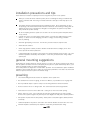
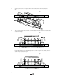
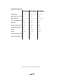
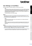
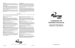
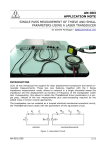
HT300iw
HT400iw
HT800iw
owner's manual
analog and digital systems
table of contents
introduction
cautions
features
installation precautions and tips
general mounting suggestions
prewiring
preparing the wall or ceiling cutout
final installation
custom painting
operation
specifications
warranty information
1
1
1-2
3
3
3
4
4-5
6
6
7
8
introduction
Congratulations, and thank you for purchasing an a/d/s/ Home Theatre in-wall speaker system. The HTseries offer the perfect combination of style and performance to meet the most exacting audio and
interior design standards. The proprietary driver design and computer-optimized crossover networks result
in a smooth, flat frequency response, which in turn yields exceptional imaging and superb transient
impact. The bass response and acoustic output capabilities of your HT series speakers are remarkable for
units of such compact dimension. a/d/s/ Home Theatre speakers are the ultimate match for your
discerning taste and lifestyle.
Be sure to save your sales receipt. It is your best record of the date of purchase, which is required for
warranty service.
Read and follow all cautions, warnings and notes.
cautions
To reduce the risk of electric shock, do not remove any parts of the speaker. There are no user serviceable
parts inside. If service is required have it performed by a qualified service professional.
WARNING
To prevent fire or shock hazard, do not expose the speakers to rain or submerge in water. The speakers
should be situated away from heat sources such as radiators, heat registers, stoves or other heat sources.
Be sure all the components in the system are turned off while making audio and power connections.
features
tweeter
The HT series incorporates the use of a 1” copolymer dome tweeter with a Ferrofluid™ damped voice coil.
tweeter protection
A solid state device reduces power to the tweeter when the loudspeaker is operated at unsafe power
levels. It resets automatically when power is reduced to a safe level. Note: the tweeter protector provides
a significant level of protection. However it does not guarantee that the tweeter cannot be damaged.
Always be careful when operating the speakers at a high volume level.
1
high frequency contour switch
A 3-position switch located on the tweeter plate serves as a high frequency contour control. The upper
position offers a “normal” response suitable for most applications. The bottom position provides the
most output and is recommended for off-axis listening or if the speakers are mounted very high. The
center position provides the least and is recommended for reflective “bright” rooms. The upper position
is the best starting point. Due to room acoustics and/or personal preference, you may prefer either of the
other positions. Be sure to try all of these positions and decide on your preference before installing the
grills. If you find it necessary to re-adjust the tweeter levels after the grills have been installed, please
follow the removing the grille section on page 6.
woofer
The HT series incorporates the use of a 5 1/4” woofer with a proprietary diaphragm made from a spherical
inverted dome sandwiches to a copolymer cone, and utilizing a strontium ferrite magnet structure for
well-damped, extended bass.
advanced industrial design
In the world of in-wall speakers, most competing products can be categorized by their incredible degree
of similarity. Regardless of the manufacturer, product offerings are limited to the same style of molded
plastic chassis, the same types of mounting systems, similar drivers and the same limited performance
capability. The HT series is a striking exception to this trend. Using the most advanced injection-molded
driver technology available, it outperforms all others in its category. Attractively styled in a neutral offwhite finish, it can be painted to perfectly match any wall.
aluminum extrusion mounting side-rails
The advantage to this design is an incredibly rigid, durable mounting system that runs the entire length of the
speaker from top to bottom. The mounting brackets do the same. As a result, the speaker is tightened to the
wall over the full length of both of its sides.
quick & easy post-construction installation
Thanks to the aluminum extrusion mounting side-rails, installation couldn’t be easier. Cut out the hole, insert the
speaker, and tighten the screws. That’s all there is to it.
engineered for critical music listening
While it is believed by many that in-walls do not do the best job of reproducing audio, a/d/s/ pushed the envelope
in engineering this line of in-walls. From beginning to end, the HT series was engineered to deliver the best
possible sonic reproduction.
d’Appolito array (HT400iw & HT800iw only)
The d’Appolito array offers symmetrical and uniform dispersion making it possible for horizontal or vertical
installation adding appeal for the home-theatre enthusiast.
“2 1/2-way” crossover (HT800iw only)
The crossover was designed using all high quality components to create smooth acoustic slopes, while the “2
1/2-way tuning” helps to add crisp, clean bass. The two center woofers and tweeter perform exactly as the
HT400iw creating a complete 2-way system. The two outside drivers are responsible only for the reproduction
of low frequencies helping to augment the bass output.
2
installation precautions and tips
Please read these instructions completely for the best enjoyment of your HT Series speakers.
When you cut into the wall to install the speaker, do not cut through the facing or insulation that
may be behind the wall. This facing is a moisture barrier. Use duct tape or wide vinyl tape to seal
any cuts.
Keep debris and loose material away from the installation location. Do not allow debris to get in
the openings of the woofer basket. Debris and loose material can cause buzzing or rattling, and can
damage the woofer cone. Install plastic or fiberglass screening above the speaker to keep debris
away. Handle the speaker carefully.
•
Do not let anything touch the speaker cone or dome. Do not clean the speaker with paint thinner
or any solvents.
Consider the services of a professional custom installer. If you have any doubts about your own
abilities, it is better not to risk damaging your walls or ceilings, electrical wiring, ventilation
ducts or plumbing.
•
Work with good quality, correct tools. This will save you time and assure superior results.
•
Allow sufficient clearance.
•
When using speakers outdoors, locations should be sheltered from direct sunlight, rain or snow.
Direct exposure will shorten product life.
•
Combined impedance for speakers connected to each channel should be at least 4 ohms. This is the
minimum impedance tolerated by most amplifiers. Check with your dealer before wiring multiple
speaker pairs.
general mounting suggestions
Avoid placing the speaker within two feet (0.6 meters) of a corner. The acoustic reflections from surfaces
near the speakers can detract from the sound quality. Do not place the speaker behind heavy fabrics; if you
cannot see through a fabric, you cannot hear through it.
The in-wall speakers are designed for "infinite baffle" operation. The area behind the speaker installation
should be at least one-half cubic foot in volume to ensure proper performance. If the area is too small it will
limit bass response and cause a peak in the mid-bass range.
prewiring
•
Check local building and electrical codes for compliance of the speaker wire.
•
Use stranded wire of at least 16 gauge; for runs over 100 feet, it is preferable to use 14 gauge wire.
•
Use only insulated staples or nylon tie straps to secure wiring within the wall to avoid shorts.
•
Do not stretch the wire as it is being routed. This could create future (and costly) problems.
•
Leave about 2-3 feet of free wire at both ends. Cutting excess wire is better than splicing.
•
Always "home run" wires: run a continuous wire from each speaker directly to the source location.
Do not connect speakers together any other way for easier diagnosis of faulty wire or speaker problems.
•
Wire speakers in phase with the same polarity. Attach positive (+/red) and negative (-/black) terminals
consistently.
•
Combined impedance for speakers connected to each channel should be at least 4 ohms. This is the
minimum impedance tolerated by most amplifiers. Check with your dealer before wiring.
3
preparing the wall or ceiling cutout
Confirm there is at least 1" between the final cutout and nearby studs or joints for positioning mounting
hardware. Temporarily fasten the stiff paper template (supplied) to the wall with thumbtacks. Carefully
trace around the perimeter with a pencil. Before making the final cutout of the entire hole, first make a
small 4-inch"test" cutout in the center of your penciled outline. Reach your hand inside to verify that
studs are outside the outline. This is an important step, since stud finders are not infallible.
To cut the actual hole, first score wallboard with a sharp knife; then use a keyhole saw to complete the
cut. Remove remaining debris from the edges. Hold the speaker up to the cutout to make sure it inserts
easily without forcing.
At this point, it is a good idea to secure the speaker wire to a stud near the cutout so its own weight will
not tug on the terminals of the speaker after it is connected. This will also prevent you from losing the
wire in the wall. Before attaching the wire, make sure the speaker wire runs through, not around, the
metal mounting bracket.
final installation
1.
a
Use the supplied cut-out templates to outline the mounting holes to be cut in the wall. Be sure the
intended hole is square and plumb.
Remove the perforated section out of the center of the template. Save this section, it will serve as
painting mask if you wish to paint the speaker in the wall. Use the inside edge of the remaining
section of the template to mark the hole size
2.
Cut the hole.
3.
Route the speaker wire from the amplifier to the speaker installation location. Secure the wires to
prevent them from falling into the wall before the speaker is mounted.
4.
Adhesive-backed foam strip-gaskets are supplied with the packing materials. These will be used to
line the back of the mounting collar flange. Remove the speaker from the corrugated shipping
sleeve. Peel the backing from the foam strip-gaskets and place them along the back of the
mounting collar flange. Cut them to size if necessary. Be sure to butt the strips up against each
other to prevent possible air leakage. Once the strips are positioned properly, press them firmly into
place. NOTE: this step is not necessary if you are installing the speaker into sheet-rock. Sheet-rock
is soft enough to compress and naturally seal the gap.
5.
Separate the two wire conductors from each other. Strip away approximately 1/4” of insulation
from each of the wire conductors. Twist the strands together into neat bundles.
6.
Push the positive (+/red) terminal to open the wire hole. Insert the positive conductor and release
the terminal to lock the wire into place. Be sure not to insert the conductor too far causing the
terminal to lock down on the insulation instead of the wire strands. Perform this same task for the
negative (-/black) terminal as well.
4
7.
Insert the speaker assembly on an angle so that one of the mounting brackets enters the opening first.
(fig. 1)
fig1
8.
Turn the speaker toward the wall so that the other mounting bracket enters the mounting hole and the speaker is
seated on the wall. (fig. 2)
fig2
9.
Hold the speaker in place in the mounting hole and begin tightening the mounting screws to draw the mounting
bracket against the backside of the wall. Gradually tighten the screws, moving from one to another, until the
speaker is firmly clamped in place. (fig. 3)
fig3
5
removing the grille
Should it be necessary to remove the grille, insert an awl or other pointed tool into a grille hole near the
corner. Gently lift the grille out of the speaker frame. Repeat this procedure at each corner of the grille,
gradually lifting the corners of the grille until it is removed. Be careful not to allow anything to touch the
woofer cones or tweeter domes while the grille is removed.
custom painting
•
Paint the speaker frame and grill before mounting to the wall; paint grill and frame separately.
•
Before painting, mask the recessed area of the speaker to completely protect the speaker drivers.
•
After painting the grill, gently blow through its perforated holes to prevent paint clogging.
operation
checking the system
Listen carefully to each speaker. If you hear buzzing or rattling noises, remove the speaker and check for
a speaker wire or other objects touching the speaker assembly. When you are satisfied with the
installation press the grills into place.
6
specifications
HT300iw HT400iw HT800iw
Mounting hole
6 3/8" x 9 1/8"
6 3/8" x 14 7/8"
6 3/8” x 26 1/2"
Depth from front of wall
3 1/4"
3 1/4"
3 1/4"
Overall dimensions
7 1/4" x 10 1/8"
7 1/4" x 15 7/8"
7 1/4" x 27 1/2"
Power range (RMS watts) 15-80
15-100
15-150
Impedance
4 ohms
8 ohms
4 ohms
Frequency response (Hz)
53-20k
45-20k
40-20k
Sensitivity 1W/1M (dB)
87dB
89dB
91dB
Woofer
5 1/4"
5 1/4" x 2
5 1/4" x 4
Tweeter
1" dome
1" dome
1" dome
Crossover frequency (Hz) 2.6k
2.4k
2.4k
Crossover slope (dB/oct)
12
12
12
(Specifications subject to change without notice)
7
warranty information
LIMITED FIVE YEAR CONSUMER WARRANTY FOR PRODUCT INSTALLED BY AN AUTHORIZED
LICENSED DEALER
Directed Electronics, Inc. promises to the original purchaser, to replace this product should it prove to be
defective in workmanship or material under normal use, for a period of five years from the date of
purchase from the dealer as indicated by the date code marking of the product PROVIDED the product
was sold by an authorized Directed dealer. During this five year period, there will be no charge for this
replacement PROVIDED the unit is returned to Directed, shipping pre-paid. This warranty is nontransferable and does not apply to any unit that has been modified or used in a manner contrary to its
intended purpose, and does not cover damage to the unit caused by installation or removal of the unit.
This warranty is void if the product has been damaged by accident or unreasonable use, neglect, improper
service or other causes not arising out of defects in material or construction. Units which are found to be
damaged by abuse resulting in thermally damaged voice coils are not covered by this warranty but may
be replaced at the absolute/sole discretion of Directed. ALL WARRANTIES INCLUDING BUT NOT
LIMITED TO EXPRESS WARRANTY, IMPLIED WARRANTY, WARRANTY OF MERCHANTABILITY,
FITNESS FOR A PARTICULAR PURPOSE , AND WARRANTY OF NON-INFRINGEMENT OF
INTELLECTUAL PROPERTY ARE EXPRESSLY EXCLUDED AND DISCLAIMED TO THE MAXIMUM
EXTENT ALLOWED BY LAW, AND DIRECTED NEITHER ASSUMES NOR AUTHORIZES ANY PERSON
TO ASSUME FOR IT ANY LIABILITY IN CONNECTION WITH THE SALE OF THE PRODUCT. DIRECTED
HAS ABSOLUTELY NO LIABILITY FOR ANY AND ALL ACTS OF THIRD PARTIES INCLUDING ITS
AUTHORIZED DEALERS OR INSTALLERS. Unit must be returned to Directed, postage pre-paid, with bill
of sale or other dated proof of purchase bearing the following information: consumer.s name, telephone
number, and address, authorized dealer.s name and address, and product description. Note: This warranty
does not cover labor costs for the removal and reinstallation of the unit. IN ORDER FOR THIS
WARRANTY TO BE VALID, YOUR UNIT MUST BE SHIPPED WITH PROOF OF SALE BY AN
AUTHORIZED DIRECTED DEALER. Some states do not allow the limitation on how long an implied
warranty lasts, so the above limitation may not apply to you. LIMITATION OF DAMAGES AND
LIABILITY: CONSUMER.S REMEDY IS LIMITED TO REPAIR OR REPLACEMENT OF THE UNIT, AND IN
NO EVENT SHALL DIRECTED.S LIABILITY EXCEED THE PURCHASE PRICE OF THE UNIT. IN ANY
EVENT, DIRECTED SHALL NOT BE LIABLE FOR ANY DAMAGES (INCLUDING, BUT NOT LIMITED TO,
ANY DIRECT, INDIRECT, INCIDENTAL, SPECIAL, PUNITIVE OR CONSEQUENTIAL DAMAGES, LOST
PROFITS, LOST SAVINGS, OR, TO THE EXTENT ALLOWED BY APPLICABLE LAW, DAMAGES
RESULTING FROM DEATH OR INJURY ARISING OUT OF OR IN CONNECTION WITH THE
INSTALLATION, USE, IMPROPER USE, OR INABILITY TO USE, THE PRODUCT, EVEN IF THE PARTY
HAS BEEN ADVISED OF THE POSSIBILITY OF SUCH DAMAGES. Some states do not allow the
exclusion of incidental or consequential damages, so the above limitation or exclusion may not apply to
you. BY PURCHASING THIS PRODUCT, THE CONSUMER AGREES AND CONSENTS THAT ALL
DISPUTES BETWEEN THE CONSUMER AND DIRECTED SHALL BE RESOLVED IN ACCORDANCE
WITH CALIFORNIA LAWS IN SAN DIEGO COUNTY, CALIFORNIA.
declaration of conformity
manufacturer name:
manufacturer address:
Directed Electronics Inc.
One Viper Way
Vista, California 92081
declares, that the product:
product name:
HT300iw
HT400iw
HT800iw
conforms to the following standards:
EN55013
EN55020
8
© Directed Electronics, Inc. All rights reserved G39556.61.71 03-05
a