1
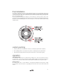
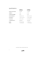
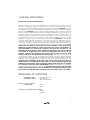
HT60ic
HT80ic
owner's manual
analog and digital systems
table of contents
introduction
cautions
about this manual
features
installation precautions and tips
general mounting suggestions
prewiring
preparing the wall or ceiling cutout
installation preparation
final installation
custom painting
operation
specifications
warranty information
1
1
1
1
2
2
3
3
3
4
4
4
5
6
introduction
Thank you for purchasing an a/d/s/ in-ceiling speaker system. Please read the following instructions
carefully. Following these instructions will ensure that your system will deliver the best possible
performance.
cautions
To reduce risk of injury because of an accident, be careful when working on a ladder or other high places.
about this manual
In-ceiling speakers can be used with many different receivers/televisions or amplifiers. They are designed
to be powered by an amplifier with a minimum of 20 watts of power.
features
tweeter
The HT series in-ceiling tweeters incorporate a 1" soft dome gimble tweeter, Ferrofluid™, and damped
voice coils.
tweeter protection
A solid state device reduces power to the tweeter when the loudspeaker is operated at unsafe power
levels. It resets automatically when power is reduced to a safe level. Note: the tweeter protector provides
a significant level of protection. However it does not guarantee that the tweeter cannot be damaged.
Always be careful when operating the speakers at a high volume level.
tweeter attenuation
The tweeter level can be adjusted with the provided switch located under the grill mesh in the speaker
mounting frame.
woofer
The high-excursion woofer employs a barium ferrite magnet structure for well damped, extended bass
and high efficiency.
pre-wire connector
Two-piece speaker wire terminals are provided to facilitate simple, painless pre-wiring and installation. Just plug
and play.
1
installation precautions and tips
Please read these instructions completely for the best enjoyment of your Custom Series speakers.
•
When you cut into the ceiling to install the speaker, do not cut through the facing or insulation that
may be above the ceiling. This facing is a moisture barrier. Use duct tape or wide vinyl tape to seal
any cuts.
•
Keep debris and loose material away from the installation location. Do not allow debris to get in
the openings of the woofer basket. Debris and loose material can cause buzzing or rattling, and can
damage the woofer cone. Install plastic or fiberglass screening above the speaker to keep debris
away. Handle the speaker carefully.
•
Do not let anything touch the speaker cone or dome. Do not clean the speaker with paint thinner
or any solvents.
•
Consider the services of a professional custom installer. If you have any doubts about your own
abilities, it is better not to risk damaging your walls or ceilings, electrical wiring, ventilation ducts
or plumbing.
•
Work with good quality, correct tools. This will save you time and assure superior results.
•
Allow sufficient clearance.
•
When using speakers outdoors, locations should be sheltered from direct sunlight, rain or snow.
Direct exposure will shorten product life.
•
Combined impedance for speakers connected to each channel must be at least 4 ohm. This is the
minimum impedance tolerated by most amplifiers. Check with your dealer before wiring multiple
speaker pairs.
general mounting suggestions
Avoid placing the speaker within two feet (0.6 meters) of a corner. The acoustic reflections from surfaces
near the speakers can detract from the sound quality. Do not place the speaker behind heavy fabrics; if
you cannot see through a fabric, you cannot hear through it.
The ceiling speakers are designed for "infinite baffle" operation. The area behind the speaker installation
should be at least one-half cubic foot in volume to ensure proper performance. If the area is too small it
will limit bass response and cause a peak in the mid-bass range.
The panel on which the speaker is mounted must be rigid. There must not be any air leaks between the
area behind the speaker and the listening area.Mounting the speaker on a panel of a suspended ceiling
will adversely affect its performance.
2
prewiring
•
Check local building and electrical codes for compliance of the speaker wire.
•
Use stranded wire of at least 16 gauge; for runs over 100 feet, it is preferable to use 14 gauge wire.
•
Use only insulated staples or nylon tie straps to secure wiring within the wall to avoid shorts.
•
Do not stretch the wire as it is being routed. This could create future (and costly) problems.
•
Leave about 2-3 feet of free wire at both ends. Cutting excess wire is better than splicing.
•
Always "home run" wires: run a continuous wire from each speaker directly to the source location.
Do not connect speakers together any other way for easier diagnosis of faulty wire or speaker problems.
•
Wire speakers in phase with the same polarity. Attach positive (+/red) and negative (-/black) terminals
consistently.
•
Combined impedance for speakers connected to each channel must be at least 4 ohm. This is the
minimum impedance tolerated by most amplifiers. Check with your dealer before wiring.
preparing the wall or ceiling cutout
Confirm there is at least 1" between the final cutout and nearby studs or joints for positioning mounting
hardware. Temporarily fasten the stiff paper template (supplied) to the wall with thumbtacks. Carefully
trace around the perimeter with a pencil. Before making the final cutout of the entire hole, first make a
small 4-inch"test" cutout in the center of your penciled outline. Reach your hand inside to verify that
studs are outside the outline. This is an important step, since stud finders are not infallible.
To cut the actual hole, first score wallboard with a sharp knife; then use a keyhole saw to complete the
cut. Remove remaining debris from the edges. Hold the speaker up to the cutout to make sure it inserts
easily without forcing.
At this point, it is a good idea to secure the speaker wire to a stud near the cutout so its own weight will
not tug on the terminals of the speaker after it is connected. This will also prevent you from "losing" the
wire in the ceiling. Before attaching the wire, make sure the speaker wire runs through, not around, the
metal mounting bracket.
installation preparation
Use the supplied template to outline the mounting hole. Cut the mounting hole and remove any debris
from the area. Take the necessary steps to keep debris from falling into the back of the speaker.
Route the wires from the amplifier to the speaker installation location. Strip about 1/2" of the insulation
from the wire conductors. Twist the wire strands of the conductors into neat bundles. Insert the wires into
the provided 2-pin plug and tighten the set screws to secure the wires. Connect the speaker plug to the
matching 2-pin jack on the cross-over board just before final mounting.
3
final installation
The speaker is held in place with four mounting clamps that are part of the assembly. When shipped from
the factory the clamps are pivoted so they will fit into the mounting hole. When the mounting hole clamp
screws are turned, the clamps pivot outward and are then drawn downward until they press against the
back of the mounting surface.
Insert the speaker/mounting bezel assembly into the mounting hole. Hold the speaker in place in the
mounting hole and evenly tighten the four mounting screws to draw the mounting brackets against the
backside of the wall. Gradually tighten the screws, moving from one to another, until the speaker is firmly
clamped in place.
custom painting
•
Paint the speaker frame and grill before mounting to the wall; paint grill and frame separately.
•
Before painting, mask the recessed area of the speaker to completely protect the speaker drivers.
•
After painting the grill, gently blow through its perforated holes to prevent paint clogging.
operation
checking the system
Listen carefully to each speaker. If you hear buzzing or rattling noises, remove the speaker and check for
a speaker wire or other objects touching the speaker assembly. Adjust the tweeter level and aim the
tweeter for the desired effect. When you are satisfied with the installation press the grills into place.
tweeter protector
If a speaker sounds "dull", or "lacks "brilliance", you may have activated the tweeter protector. If high
power operation causes the tweeter to stop playing, turn down the volume control until normal sound
resumes.
4
specifications
HT60ic
HT80ic
frequency response (Hz)
65-20 kHz
58-20 kHz
impedance
4 ohm
4 ohm
sensitivity 1W/1M (dB)
88 dB
88 dB
max bezel diameter
9-1/4" (23.5 cm)
10-7/8" (27.6 cm)
mounting hole
7-11/16" (19.5 cm)
9-7/16" (24.0 cm)
rear clearance
3-1/2" (8.9 cm)
4-1/8" (10.5 cm)
recommended power
20-80 watts
20-80 watts
woofer
6-1/2" (16.5 cm)
8" (20.3 cm)
tweeter
1" (25 mm) dome
1" (25 mm) dome
(Specifications subject to change without notice)
5
warranty information
LIMITED TWO YEAR CONSUMER WARRANTY
Directed Electronics, Inc. promises to the original purchaser, to replace this product should it prove to be
defective in workmanship or material under normal use, for a period of two years from the date of
purchase from the dealer as indicated by the date code marking of the product PROVIDED the product
was installed by an authorized Directed dealer. During this two-year period, there will be no charge for
this replacement PROVIDED the unit is returned to Directed, shipping pre-paid. If the unit is installed by
anyone other than an authorized Directed dealer, the warranty period will be one year from the date of
purchase by the dealer as indicated by the date code marking of the product. This warranty is nontransferable and does not apply to any unit that has been modified or used in a manner contrary to its
intended purpose, and does not cover damage to the unit caused by installation or removal of the unit.
During this one-year period, there will be no charge for this replacement PROVIDED the unit is returned
to Directed, shipping pre-paid. This warranty is void if the product has been damaged by accident or
unreasonable use, neglect, improper service or other causes not arising out of defects in materials or
construction. Units which are found to be damaged by abuse resulting in thermally damaged voice coils
are not covered by this warranty but may be replaced at the absolute/sole discretion of Directed. ALL
WARRANTIES INCLUDING BUT NOT LIMITED TO EXPRESS WARRANTY, IMPLIED WARRANTY,
WARRANTY OF MERCHANTABILITY, FITNESS FOR PARTICULAR PURPOSE, AND WARRANTY OF
NON-INFRINGEMENT OF INTELLECTUAL PROPERTY ARE EXPRESSLY EXCLUDED TO THE
MAXIMUM EXTENT ALLOWED BY LAW, AND DIRECTED NEITHER ASSUMES NOR AUTHORIZES
ANY PERSON TO ASSUME FOR IT ANY LIABILITY IN CONNECTION WITH THE SALE OF THE
PRODUCT. DIRECTED HAS ABSOLUTELY NO LIABILITY FOR ANY AND ALL ACTS OF THIRD
PARTIES INCLUDING ITS AUTHORIZED DEALERS OR INSTALLERS. Unit must be returned to Directed,
postage pre-paid, with bill of sale or other dated proof of purchase bearing the following information:
consumer's name, telephone number, and address, authorized dealer's name and address, and product
description. Note: This warranty does not cover labor costs for the removal and reinstallation of the unit.
IN ORDER FOR THIS WARRANTY TO BE VALID, YOUR UNIT MUST BE SHIPPED WITH PROOF OF
INSTALLATION BY AN AUTHORIZED DIRECTED DEALER. ALL UNITS RECEIVED BY DIRECTED FOR
WARRANTY REPAIR WITHOUT PROOF OF DIRECTED DEALER INSTALLATION WILL BE COVERED
BY THE LIMITED 1 YEAR PARTS AND LABOR WARRANTY. Note: This warranty does not cover labor
costs for the removal and reinstallation of the unit. BY PURCHASING THIS PRODUCT, THE CONSUMER
AGREES AND CONSENTS THAT ALL DISPUTES BETWEEN THE CONSUMER AND DIRECTED SHALL
BE RESOLVED IN ACCORDANCE WITH CALIFORNIA LAWS IN SAN DIEGO COUNTY, CALIFORNIA.
declaration of conformity
manufacturer name:
manufacturer address:
Directed Electronics Inc.
One Viper Way
Vista, California 92083
declares, that the product:
product name:
HT60ic
HT80ic
conforms to the following standards:
EN55013
EN55020
6
Directed Electronics, Inc. All rights reserved G39630/35 8-03
a