1
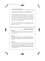
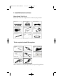
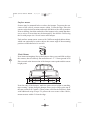
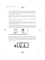
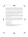
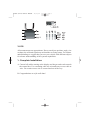
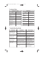
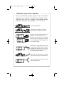
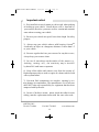
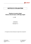
P5000 Series Owners Manual
12/16/04
5:16 PM
Page 1
Owners Manual
P5000 Series Owners Manual
C
12/16/04
5:16 PM
Page 2
ongratulations, You have made a wise investment and an excellent
choice in selecting a Precision Park System by Ackton.
Your Precision Park system utilizes the latest technology and quality
components to provide you and your family with years of reliable service.
Ackton's products have over 20 years of reverse sensing experience and are
manufactured to demanding ISO 9001 and QS 9000 standards. Quality, that
has earned the strict European TUV certification.
A great amount of care went into building your Precision Park system.
Please take the time to read the manual carefully before installing, as we
want you to be as proud of your installation, as we are of the product.
Thank You, for your purchase and safe motoring, From all of us at Ackton Inc.
Precision Park Limited Warranty
This Warranty covers defects in workmanship and materials for a period
of twelve (12) months from date of purchase. It does not cover any unit
that is damaged due to improper installation, or mishandling beyond normal
use, or other acts or omissions not sanctioned by the Owner's Manual. The
owner is required to return the defective product to their place of purchase
and provide dated proof of purchase. The authorized dealer will determine
if there is a warrantable condition. If a warrantable condition exists, the
component will be replaced or repaired free of charge. The owner is
responsible for any labor and installation charges. The Warranty does not
include any further obligation whatsoever, including but not limited to
actual installation of the replacement unit on the customer's vehicle. No
other warranty is expressed or implied. The absolute limit of liability is
the purchase price of the unit. Ackton Inc. is not liable for any direct,
consequential, indirect or punitive damages of any kind.Some states do not
allow limits on the validity or length of implied warranties or exclusions
or limitations of incidental or consequentiadamages, so this warranty may
not apply to you. This warranty gives you specific legal rights and other
rights may which vary from state to state.
2
P5000 Series Owners Manual
12/16/04
5:16 PM
Page 3
Function Specification
The Precision Park 5000 system consists of four ultrasonic sensors,
one control unit, one wiring harness and one display/speaker.
The sensors operate both as transmitters and as receivers, which send
an ultra high frequency sound wave (sonar) that is reflected off an
object and received. The distance from the obstacle is evaluated through
the transit time of the signals and is indicated by a sequence of pulse
tones, the closer the obstacle, the faster the sequence of pulse tones.
The distance to the obstacle and obstacle location are communicated
to the driver via a 5 color LED display.
The sensors mount into or attach to the rear bumper. The control
module mounts beneath the vehicle with the display mounted to the
dash in view of the driver.
Safety Precautions
Warning!
Safety precaution: Failure to observe the instructions could damage
the device and impair its function as well as cause injury due to
electrical current.
Warning!
Due to the risk of short circuit, always disconnect the negative pole
of the battery before starting work. Disconnecting the negative pole
of the battery may result in loss of system memory and may need to
be reset.
Warning!
Precision Park is intended as a parking aid. Due to the nature of the
system, some obstacles may not be detected or may be identified
inaccurately due to physical reflection properties. The system does
not relieve the driver of their responsibility to exercise caution when
reversing and to obey the safety rules and regulations given by the
vehicle manufacturer.
3
P5000 Series Owners Manual
12/16/04
5:16 PM
Page 4
I. Installation Instructions
Material and Tool Check
Insure that all of the components are in the kit, they include:
Sensors ( 4)
Control Module (1)
Sensor Cables (4)
Display & Cable (1)
Velcro Pad
(1)
Splice
Connectors
(2)
Cable Ties (10)
Sensor angle shims(12)
Manual
(1)
Tools required to install the system:
Alcohol
Wipe
Electric
Tape
Pilot drill bit
Power Drill
Pliers or
Crimp Tool
Elec.Test Light
Tape measure
Safty
Glasses
Other common tools may be requiredfor your specific application.
4
P5000 Series Owners Manual
12/16/04
5:16 PM
Page 5
II. Sensor Installation
Sensor installation will depend on the sensors supplied with the system
either flush mount or surface mount. Locate your sensor type from the
sensors below.
flush mount
flush mount with
adjustable angle
surface mount
NOTE:
The driver's side is considered the left side of the vehicle.
The sensors are marked:
R=Right, CR=Center Right, CL=Center Left, L=Left
45-60cm
Begin by parking on a flat level surface, set brake and disconnect ground
wire from battery. Measure the length of the bumper and mark the center
point with a mark on masking tape. Divide the bumper as shown below.
To protect the rear corner of the vehicle, mount sensors within 1' from
the bumper ends.
1/8
approx
2/8
approx
2/8
approx
5
2/8
approx
1/8
approx
P5000 Series Owners Manual
12/16/04
5:16 PM
Page 6
Surface mount
Sensors may be mounted below or above the bumper. To protect the rear
corner of the vehicle, mount sensors within 1' from the edge. Place the
sensors at the desired locations and mark drill holes with a felt tip marker.
Prior to drilling, check the underside of the bumper to be certain that there
are no wires or items that may be damaged by the drill bit. Drill using
the bit with proper size. Screw sensor onto bumper.
Each surface mount sensor comes with 3 different angled rubber shims,
which can optionally be used to adjust the sensor angle if the mounting
position would otherwise be too low.
Flush Mount
45-60cm
Next locate an imaginary line on the bumper where you would like to align
the sensors, that is relatively flat and between 1.5' - 2' from ground level.
Place a mark at the intersection of the bumper center-point and the sensor
height point.
1/8
approx
2/8
approx
2/8
approx
2/8
approx
1/8
approx
Near the ends of the bumper, mark the same sensor height on masking
tape creating 3 points along the bumper. Run a strip of tape so the top of
the tape connects all 3 points. (These points will form the drill line), mark
with additional strips of tape. To protect the rear corner of the vehicle,
mount sensors within 1' from the edge.
6
P5000 Series Owners Manual
12/16/04
5:16 PM
Page 7
Prior to drilling check the underside of the bumper to be certain that
there are no wires or items that may be damaged by the drill bit. Leave
the tape on when drilling to reduce any chipping of the paint that may
occur around the opening
Drill a pilot hole or use the pilot bit to drill the proper holes for sensor
placement. (Use straight steel bit when drilling into a steel bumper). Remove
tape.
Dig out foam in the sensor holes as necessary so as not to inhibit sensor
fitting or crimp the sensor cables.
Drop the cable through the hole. Gently pull the cables through the hole and
push the correct sensor into position. Push on the sensor edges only until
it's fitted into the bumper.
Your sensors may have a slight angle built into the plastic in this case (in some
model), place the thick part facing down. Do not force the sensor; a too tight
fitting may result in false alerts. Burnish the edge of the hole and re-insert.
III. Control Box & Display Installation:
Before assembly, loose fit the water resistant control module in a location
that minimizes stone damage, away from extreme heat and severe water
ingress. Find a suitable location for the display on the dash then check the
length of the cables to insure that desired placement is possible given the
product components.
7
P5000 Series Owners Manual
12/16/04
5:16 PM
Page 8
Attach sensor cable extensions and cable tie the sensor cables to conceal.
Be certain the cables will reach the control module then fasten the control
module using the screws provided. Attach the sensor cables to the control
module. Be sure to match the correct sensor location with the module inputs.
Clean the display location with alcohol and attach display to dash. Run the
display cable through an existing grommet. Cut grommet if necessary to
run the cables through. If there is no access from the cab drill a hole suitable
for the cables to pass and line with a grommet. Run display cable to control
module and attach. Cable tie the display cable and conceal
(5000 Wireless use Display) Splice red (+) power lead into a keyed circuit
or run to fuse box. Splice or attach black (-) ground wire to sufficient ground.
Clean the display location with alcohol and attach display to dash. Cable tie
power cable and conceal.
Identify the power wire to the reverse lights using a test light. Connect the
Red positive wire from the control box to the reverse lights positive lead,
and the Black ground wire to the reverse light's ground or other ground
using the splice connectors supplied. Electrical tape or shrink-wrap the
splices for additional protection
IV. System Check:
A. Re-connect battery
B. Engage brake, turn the ignition on
C. Shift transmission into reverse and make certain reverse lights are on.
Two beeps from the display indicates the system is active.
D. Note detection patterns and alerts levels below.
8
P5000 Series Owners Manual
12/16/04
5:16 PM
Page 9
0-2F
2-4F
4-6F
NOTE:
All measurements are approximate. Due to an objects position, angle, size
or shape, the reflected signal may mislead the receiving sensor. For a better
understanding we suggest that you test your vehicle with different objects
for a better understanding of the systems capabilities.
V. Complete Installation:
A. Conceal all cables starting at the display and beeper and work towards
the control box. Use remaining cable ties to bundle any excess cable or
wire. Be certain excess wire is secured and out of the way.
B. Congratulations on a job well done!
9
P5000 Series Owners Manual
12/16/04
5:16 PM
Page 10
Technical Data
CONTROL BOX
SENSOR
ITEM
SPECIFICATION
ITEM
SPECIFICATION
Specified voltage
DC12V
AC 90~130V P-P
Operation voltage
range
DC10.8~15V
Operation voltage
range
Standby current
Below 100MA
Operating current
Below 200MA
Operating
temperatur e
-30 C~80 C
Storage
temperature
-35 C~85 C
Operating
Temperatur e
-30 C~80 C
Operating
frequency
40KHz ± 2KHz
Storage
Temperatur e
-35 C~85 C
Detection angle
120 Horizontal
60 Vertical
Detection method
Ultrasonic wave
Operation
frequency
40KHz ± 2KHz
Trouble-Shooting Guide
PROBLEM
System does not
work when reverse
gear is engaged
Audio alarm/same
distance displayed
continuously
No audio alarm
when obstacle is in
detection range
False alarm
REASON
SOLUTION
Bad connection of main
power lead
Check power lead
Bad jack connection
Reconnect all jacks
Reset the system
Sensor detects the ground
Adjust angle of sensor
installation
Reset the system
Bad sensor connection
Reconnect sensors
Sensor detects the ground
Adjust angle of sensor
installation
System sensitivity is
too high
Ask your dealer/pro fessional installer to
adjust sensitivity
10
P5000 Series Owners Manual
12/16/04
5:16 PM
Page 11
Obstacles may not be detected
Due to the obstacle's position, angle or size, the reflected
signal may not reach the receiving sensor . Complex reflections may also occur in a complex environment causing
inaccurate detection. See examples 1, 2, 3, 4, 5 and 6.
Low lying obstacle
A
B
C
A
B
B
Complex environment: B will be
detected but A cannot be detected.
Distance A will be detected first, then
distance B, as the car reverses.
However, as the car nears, A will fall
into the sensor 's blind zone. In such
cases, the system will misjudge B as
the closest distance.
When the car approaches a glass wall
(or any other smooth surface) almost
paralleled to the body of the car, the
wall may not be detected as most of
the signal is reflected away.
When the car approaches a smooth
slope, the slope may not be detected.
The system may not detect a small,
r ound, smooth pole.
11
P5000 Series Owners Manual
12/16/04
5:16 PM
Page 12
Important notice!
1). Precision Park is strictly meant as a drivers aid when parking
or backing up your vehicle. Not all objects will be detected by
your sensors, therefore you must exercise caution and common
sense when reversing your vehicle.
2). Reverse your vehicle at a speed lower than 6mph for safety
purpose.
3). Always stop your vehicle when a solid beeping is heard as
it indicates an object in a dangerous distance no more than 1.5'
to your vehicle.
4). Execute regular check on your sensors for any dirt or snow,
always keep your sensors clean.
5). In case of water drops on the surface of the sensor (e.g.,
wash ing , rainin g ...etc.) , the sensitivi ty may be decreased
by about 20% until water evaporates.
6). Keep all the cables and sensors away from the vicinity of
high temperature objects such as engine or exhaust which could
cause system failure.
7). Precision Park components are complex, opening by user
may damage its completeness. The manufacturer or its distributors
sh all NOT take any responsibility for equipment that has been
tampered with by the user .
8). In case of defective sensor, please check the cable for color
coding, match a replacement sensor with the same color code.
ACKTON INC.
Tel: 949-770-8899
Fax:949-770-8892
12
www.ackton.com