1
TravelMate 8172/8172Z Series
Service Guide
Service guide files and updates are available
on the ACER/CSD web; for more information,
please refer to http://csd.acer.com.tw
PRINTED IN TAIWAN
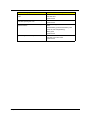
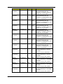
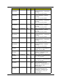
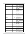
Revision History
Please refer to the table below for the updates made on TravelMate 8172/8172Z service guide.
Date
2
Chapter
Updates
Copyright
Copyright © 2010 by Acer Incorporated. All rights reserved. No part of this publication may be reproduced,
transmitted, transcribed, stored in a retrieval system, or translated into any language or computer language, in
any form or by any means, electronic, mechanical, magnetic, optical, chemical, manual or otherwise, without
the prior written permission of Acer Incorporated.
Disclaimer
The information in this guide is subject to change without notice.
Acer Incorporated makes no representations or warranties, either expressed or implied, with respect to the
contents hereof and specifically disclaims any warranties of merchantability or fitness for any particular
purpose. Any Acer Incorporated software described in this manual is sold or licensed “as is”. Should the
programs prove defective following their purchase, the buyer (and not Acer Incorporated, its distributor, or its
dealer) assumes the entire cost of all necessary servicing, repair, and any incidental or consequential
damages resulting from any defect in the software.
Acer is a registered trademark of Acer Corporation.
Intel is a registered trademark of Intel Corporation.
Pentium and Pentium II/III are trademarks of Intel Corporation.
Other brand and product names are trademarks and/or registered trademarks of their respective holders.
3
Conventions
The following conventions are used in this manual:
4
SCREEN
MESSAGES
Denotes actual messages that appear
on screen.
NOTE
Gives bits and pieces of additional
information related to the current
topic.
WARNING
Alerts you to any damage that might
result from doing or not doing specific
actions.
CAUTION
Gives precautionary measures to
avoid possible hardware or software
problems.
IMPORTANT
Reminds you to do specific actions
relevant to the accomplishment of
procedures.
Preface
Before using this information and the product it supports, please read the following general information.
1.
This Service Guide provides you with all technical information relating to the BASIC CONFIGURATION
decided for Acer's “global” product offering. To better fit local market requirements and enhance product
competitiveness, your regional office MAY have decided to extend the functionality of a machine (e.g.
add-on card, modem, or extra memory capability). These LOCALIZED FEATURES will NOT be covered
in this generic service guide. In such cases, please contact your regional offices or the responsible
personnel/channel to provide you with further technical details.
2.
Please note WHEN ORDERING FRU PARTS, that you should check the most up-to-date information
available on your regional web or channel. If, for whatever reason, a part number change is made, it will
not be noted in the printed Service Guide. For ACER-AUTHORIZED SERVICE PROVIDERS, your Acer
office may have a DIFFERENT part number code to those given in the FRU list of this printed Service
Guide. You MUST use the list provided by your regional Acer office to order FRU parts for repair and
service of customer machines.
5
6
Table of Contents
System Specifications
1
System Block Diagram . . . . . . . . . . . . . . . . . . . . . . . . . . . . . . . . . . . . . . . . . . . . . . . . .5
Board Layout . . . . . . . . . . . . . . . . . . . . . . . . . . . . . . . . . . . . . . . . . . . . . . . . . . . . . . . .6
Top View . . . . . . . . . . . . . . . . . . . . . . . . . . . . . . . . . . . . . . . . . . . . . . . . . . . . . . . .6
Bottom View . . . . . . . . . . . . . . . . . . . . . . . . . . . . . . . . . . . . . . . . . . . . . . . . . . . . .7
Your Acer Notebook tour . . . . . . . . . . . . . . . . . . . . . . . . . . . . . . . . . . . . . . . . . . . . . . .9
Top View . . . . . . . . . . . . . . . . . . . . . . . . . . . . . . . . . . . . . . . . . . . . . . . . . . . . . . . .9
Closed Front View . . . . . . . . . . . . . . . . . . . . . . . . . . . . . . . . . . . . . . . . . . . . . . . .10
Rear view . . . . . . . . . . . . . . . . . . . . . . . . . . . . . . . . . . . . . . . . . . . . . . . . . . . . . .10
Left View . . . . . . . . . . . . . . . . . . . . . . . . . . . . . . . . . . . . . . . . . . . . . . . . . . . . . . .11
Right View . . . . . . . . . . . . . . . . . . . . . . . . . . . . . . . . . . . . . . . . . . . . . . . . . . . . . .11
Base view . . . . . . . . . . . . . . . . . . . . . . . . . . . . . . . . . . . . . . . . . . . . . . . . . . . . . .12
Touchpad Basics (with fingerprint reader) . . . . . . . . . . . . . . . . . . . . . . . . . . . . .13
Touchpad basics (with two-click buttons) . . . . . . . . . . . . . . . . . . . . . . . . . . . . . .14
Using the Keyboard . . . . . . . . . . . . . . . . . . . . . . . . . . . . . . . . . . . . . . . . . . . . . . . . . .15
Lock Keys and embedded numeric keypad* . . . . . . . . . . . . . . . . . . . . . . . . . . . .15
Windows Keys . . . . . . . . . . . . . . . . . . . . . . . . . . . . . . . . . . . . . . . . . . . . . . . . . .16
Hot Keys . . . . . . . . . . . . . . . . . . . . . . . . . . . . . . . . . . . . . . . . . . . . . . . . . . . . . . .17
Using the system utilities . . . . . . . . . . . . . . . . . . . . . . . . . . . . . . . . . . . . . . . . . . . . . .18
Acer Backup Manager . . . . . . . . . . . . . . . . . . . . . . . . . . . . . . . . . . . . . . . . . . . .20
Power management . . . . . . . . . . . . . . . . . . . . . . . . . . . . . . . . . . . . . . . . . . . . . .21
Acer PowerSmart key . . . . . . . . . . . . . . . . . . . . . . . . . . . . . . . . . . . . . . . . . . . . .21
Acer eRecovery Management . . . . . . . . . . . . . . . . . . . . . . . . . . . . . . . . . . . . . .21
Burn backup discs . . . . . . . . . . . . . . . . . . . . . . . . . . . . . . . . . . . . . . . . . . . . . . . .22
Restore . . . . . . . . . . . . . . . . . . . . . . . . . . . . . . . . . . . . . . . . . . . . . . . . . . . . . . . .22
Hardware Specifications and Configurations . . . . . . . . . . . . . . . . . . . . . . . . . . . . . . .24
BIOS Setup Utility . . . . . . . . . . . . . . . . . . . . . . . . . . . . . . . . . . . . . . . . . . . . . . . . . . . .29
System Utilities
29
Invoking BIOS Setup . . . . . . . . . . . . . . . . . . . . . . . . . . . . . . . . . . . . . . . . . . . . . . . . .30
Information . . . . . . . . . . . . . . . . . . . . . . . . . . . . . . . . . . . . . . . . . . . . . . . . . . . . .30
Main . . . . . . . . . . . . . . . . . . . . . . . . . . . . . . . . . . . . . . . . . . . . . . . . . . . . . . . . . .31
Security . . . . . . . . . . . . . . . . . . . . . . . . . . . . . . . . . . . . . . . . . . . . . . . . . . . . . . . .33
Boot . . . . . . . . . . . . . . . . . . . . . . . . . . . . . . . . . . . . . . . . . . . . . . . . . . . . . . . . . . .36
Exit . . . . . . . . . . . . . . . . . . . . . . . . . . . . . . . . . . . . . . . . . . . . . . . . . . . . . . . . . . .36
BIOS Flash Utility . . . . . . . . . . . . . . . . . . . . . . . . . . . . . . . . . . . . . . . . . . . . . . . . . . . .39
DOS flash BIOS SOP . . . . . . . . . . . . . . . . . . . . . . . . . . . . . . . . . . . . . . . . . . . . . . . . .40
Clean BIOS Password SOP . . . . . . . . . . . . . . . . . . . . . . . . . . . . . . . . . . . . . . . . . . . .43
Clean HDD Password SOP . . . . . . . . . . . . . . . . . . . . . . . . . . . . . . . . . . . . . . . . . . . .48
Crisis Disk SOP . . . . . . . . . . . . . . . . . . . . . . . . . . . . . . . . . . . . . . . . . . . . . . . . . . . . .54
DMI Utility SOP . . . . . . . . . . . . . . . . . . . . . . . . . . . . . . . . . . . . . . . . . . . . . . . . . . . . . .57
LAN EEPROM Utility SOP . . . . . . . . . . . . . . . . . . . . . . . . . . . . . . . . . . . . . . . . . . . . .61
Winflash SOP . . . . . . . . . . . . . . . . . . . . . . . . . . . . . . . . . . . . . . . . . . . . . . . . . . . . . . .65
Disassembly Requirements . . . . . . . . . . . . . . . . . . . . . . . . . . . . . . . . . . . . . . . .69
Related Information . . . . . . . . . . . . . . . . . . . . . . . . . . . . . . . . . . . . . . . . . . . . . . .69
Replacement Requirements . . . . . . . . . . . . . . . . . . . . . . . . . . . . . . . . . . . . . . . .69
. . . . . . . . . . . . . . . . . . . . . . . . . . . . . . . . . . . . . . . . . . . . . . . . . . . . . . . . . . . . . .69
Machine Disassembly and Replacement
69
Pre-disassembly Instructions . . . . . . . . . . . . . . . . . . . . . . . . . . . . . . . . . . . . . . .70
Disassemble Process . . . . . . . . . . . . . . . . . . . . . . . . . . . . . . . . . . . . . . . . . . . . .71
External Module Disassembly Process . . . . . . . . . . . . . . . . . . . . . . . . . . . . . . . .71
Removing the Battery Pack . . . . . . . . . . . . . . . . . . . . . . . . . . . . . . . . . . . . . . . .72
Removing the HDD. . . . . . . . . . . . . . . . . . . . . . . . . . . . . . . . . . . . . . . . . . . . . . .74
1
Table of Contents
Removing the DIMM module . . . . . . . . . . . . . . . . . . . . . . . . . . . . . . . . . . . . . . .78
Remove the Wireless module . . . . . . . . . . . . . . . . . . . . . . . . . . . . . . . . . . . . . . .81
LCD Module Disassembly Process . . . . . . . . . . . . . . . . . . . . . . . . . . . . . . . . . . .83
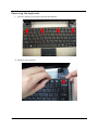
Removing the keyboard . . . . . . . . . . . . . . . . . . . . . . . . . . . . . . . . . . . . . . . . . . .84
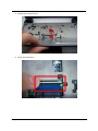
Removing the Upper Case . . . . . . . . . . . . . . . . . . . . . . . . . . . . . . . . . . . . . . . . .87
Removing the LCD Module . . . . . . . . . . . . . . . . . . . . . . . . . . . . . . . . . . . . . . . . .91
Removing the Bluetooth Module . . . . . . . . . . . . . . . . . . . . . . . . . . . . . . . . . . . . .98
Removing the Mainboard . . . . . . . . . . . . . . . . . . . . . . . . . . . . . . . . . . . . . . . . .100
LCD Module Disassembly Process . . . . . . . . . . . . . . . . . . . . . . . . . . . . . . . . . .113
Removing the Mainboard . . . . . . . . . . . . . . . . . . . . . . . . . . . . . . . . . . . . . . . . .114
Removing the Camera Board . . . . . . . . . . . . . . . . . . . . . . . . . . . . . . . . . . . . . .118
Remove the Antennas . . . . . . . . . . . . . . . . . . . . . . . . . . . . . . . . . . . . . . . . . . .119
LCD Reassembly . . . . . . . . . . . . . . . . . . . . . . . . . . . . . . . . . . . . . . . . . . . . . . . . . . .124
Replacing the Antenna . . . . . . . . . . . . . . . . . . . . . . . . . . . . . . . . . . . . . . . . . . .124
Replacing the Camera Board . . . . . . . . . . . . . . . . . . . . . . . . . . . . . . . . . . . . . .128
Replace the Wireless LAN Module . . . . . . . . . . . . . . . . . . . . . . . . . . . . . . . . . .129
Replacing LCM Module . . . . . . . . . . . . . . . . . . . . . . . . . . . . . . . . . . . . . . . . . . .130
Replacing the Mainboard . . . . . . . . . . . . . . . . . . . . . . . . . . . . . . . . . . . . . . . . .135
Replacing the Panel . . . . . . . . . . . . . . . . . . . . . . . . . . . . . . . . . . . . . . . . . . . . .144
Replacing the Bluetooth Module . . . . . . . . . . . . . . . . . . . . . . . . . . . . . . . . . . . .151
Replacing the Upper Case . . . . . . . . . . . . . . . . . . . . . . . . . . . . . . . . . . . . . . . .152
Replacing the keyboard . . . . . . . . . . . . . . . . . . . . . . . . . . . . . . . . . . . . . . . . . .156
Replace the Wireless LAN Module . . . . . . . . . . . . . . . . . . . . . . . . . . . . . . . . . .158
Replace the DIMM module . . . . . . . . . . . . . . . . . . . . . . . . . . . . . . . . . . . . . . . .159
Replacing HDD module . . . . . . . . . . . . . . . . . . . . . . . . . . . . . . . . . . . . . . . . . .162
Replacing the battery . . . . . . . . . . . . . . . . . . . . . . . . . . . . . . . . . . . . . . . . . . . .164
Troubleshooting
165
System Check Procedures . . . . . . . . . . . . . . . . . . . . . . . . . . . . . . . . . . . . . . . . . . . .166
External Diskette Drive Check . . . . . . . . . . . . . . . . . . . . . . . . . . . . . . . . . . . . .166
External CD-ROM Drive Check . . . . . . . . . . . . . . . . . . . . . . . . . . . . . . . . . . . .166
Keyboard or Auxiliary Input Device Check . . . . . . . . . . . . . . . . . . . . . . . . . . . .166
Memory check . . . . . . . . . . . . . . . . . . . . . . . . . . . . . . . . . . . . . . . . . . . . . . . . . .167
Power System Check . . . . . . . . . . . . . . . . . . . . . . . . . . . . . . . . . . . . . . . . . . . .167
Touchpad Check . . . . . . . . . . . . . . . . . . . . . . . . . . . . . . . . . . . . . . . . . . . . . . . .168
Power-On Self-Test (POST) Error Message . . . . . . . . . . . . . . . . . . . . . . . . . . . . . .169
Index of Error Messages . . . . . . . . . . . . . . . . . . . . . . . . . . . . . . . . . . . . . . . . . . . . . .170
InsydeH2O BIOS Beep Codes . . . . . . . . . . . . . . . . . . . . . . . . . . . . . . . . . . . . . . . . .173
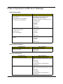
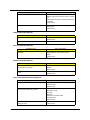
Index of Symptom-to-FRU Error Message . . . . . . . . . . . . . . . . . . . . . . . . . . . . . . . .177
Intermittent Problems . . . . . . . . . . . . . . . . . . . . . . . . . . . . . . . . . . . . . . . . . . . . . . . .181
Undetermined Problems . . . . . . . . . . . . . . . . . . . . . . . . . . . . . . . . . . . . . . . . . . . . . .182
Jumper and Connector Locations
183
Top View . . . . . . . . . . . . . . . . . . . . . . . . . . . . . . . . . . . . . . . . . . . . . . . . . . . . . . . . . .183
Bottom View. . . . . . . . . . . . . . . . . . . . . . . . . . . . . . . . . . . . . . . . . . . . . . . . . . . . . . . .184
FRU (Field Replaceable Unit) List
187
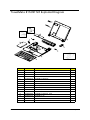
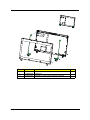
TravelMate 8172/8172Z Exploded Diagram . . . . . . . . . . . . . . . . . . . . . . . . . . . . . . .188
TravelMate 8172/8172Z FRU List . . . . . . . . . . . . . . . . . . . . . . . . . . . . . . . . . . . . . . .191
Model Definition and Configuration
203
Test Compatible Components
223
Online Support Information
231
2
Chapter 1
System Specifications
Features
Below is a brief summary of the computer’s many features:
Operating system
Genuine Windows® 7 Professional 32-bit
Genuine Windows® 7 Home Premium 64-bit
CPU and chipset
Intel® Core™ i5-430UM/i5-520UM/i5-540UM processor (3 MB L3 cache, 1.20/1.06/1.20 GHz with Turbo
Boost up to 1.73/1.86/2 GHz, DDR3 800 MHz, 18 W), supporting Intel® 64 architecture, Intel® Smart
Cache
Intel® Core™ i3-330UM processor (3 MB L3 cache, 1.20 GHz, DDR3 800 MHz, 18 W), supporting Intel®
64 architecture, Intel® Smart Cache
Mobile Intel® HM55 Express Chipse (for TM8172Z)
Memory
Dual-channel DDR3 SDRAM support:
z
Up to 2 GB of DDR3 system memory, upgradable to 4 GB using two soDIMM modules
Display and graphics
11.6" HD 1366 x 768 (WXGA) pixel resolution, high-brightness (200-nit) LED-backlit TFT LCD
Mercury-free environment friendly
Intel® HD Graphics with 128 MB of dedicated system memory, supporting Microsoft® DirectX® 10
Dual independent display support
16.7 million colors
External resolution / refresh rate:
z VGA port up to 2560 x 1600 : 60 Hz
MPEG-2/DVD decoding
WMV9 (VC-1) and H.264 (AVC) decoding
Storage subsystem
Hard disk drive:
z 160/250/320/500/640 GB or larger
Multi-in-1 card reader, supporting:
z Secure Digital™ (SD) Card, MultiMediaCard™(MMC), Memory Stick™ (MS), Memory Stick
PRO™(MS PRO), xD-Picture Card™(xD)
z Supported 8GB (test pass)
Chapter 1
1
Dimensions and weight
Dimensions:
z 285 (W) x 206.3 (D) x 20.2/29.1 (H) mm (11.22 x 8.12 x 0.795/ 1.146 inches)
Weight:
z 1.35 kg (2.97 lbs.) with 6-cell battery pack (non-3G model)
Power adapter and battery
ACPI 3.0 CPU power management standard: supports Standby and Hibernation power-saving modes
Power adapter:2-pin 40 W Acer MiniGo AC adapter
z 93.2 (W) x 32.2 (D) x 42.5 (H) mm (3.66 x 1.26 x 1.67 inches)
z 180 g (0.39 lbs.) with 250 cm DC cable
z 210 g (0.47 lbs.) with 250 cm DC cable and one AC power plug
Battery
24 W 2200 mAh 3-cell Li-ion battery pack
Battery life: 3 hours
48 W 4400 mAh 6-cell Li-ion battery pack
Battery life: 6 hours
63 W 5600 mAh 6-cell Li-ion battery pack
Battery life: 8 hours
ENERGY STAR®
Input and control
Keyboar
z 84-/85-/88-key full-size Acer FineTip keyboard with international language support
Touchpad
z Multi-gesture touchpad, supporting two-finger scroll, pinch, rotate, flip
Control key
z Acer Bio-Protection fingerprint reader
Audio
Two built-in stereo speakers
High-definition audio support
MS-Sound compatible
Built-in microphone
Webcam
Acer Video Conference, featuring:
z Acer Crystal Eye webcam with 1280 x 1024 resolution
z Acer Video Conference Manager software, featuring Video Quality Enhancement (VQE) technology,
supporting 640 x 480 resolution online video calls
Wireless and networking
WLAN:
z Acer InviLink™ Nplify™ 802.11b/g/n Wi-Fi CERTIFIED™
z Acer InviLink™ 802.11b/g Wi-Fi CERTIFIED™
z Supporting Acer SignalUp™wireless technology
2
Chapter 1
WPAN: BluetoothR 3.0+HS
WWAN: UMTS/HSPA at 900/2100 MHz and quad-band GSM/GPRS/EDGE at 850/900/1800/1900 MHz,
upgradable to 7.2 Mb/s HSDPA and 5.7 Mb/s HSUPA (for 3G model)
LAN: Gigabit Ethernet, Wake-on-LAN ready
Input and output
Acer Easyport IV connector
Multi-in-1 card reader (SD, MMC, MS, MS PRO, xD)
Three USB 2.0 ports
External display (VGA) port
Headphone/speaker/line-out jack
Microphone-in jack
Ethernet (RJ-45) port
DC-in jack for AC adapter
Security
Acer Bio-Protection fingerprint solution, featuring Pre-Boot Authentication (PBA), computer protection,
Acer FingerLaunch
BIOS user, supervisor, HDD passwords
Kensington lock slot
Software
Productivity
z Acer ePower Management
z Acer eRecovery Management
z Adobe® Flash® Player 10
z Adobe® Reader® 9.1
z eSobi™
z Google Toolbar™
z Microsoft® Office Personal 2007 (Service Pack 2)(Japan only, subject to customer request)
z Microsoft® Office Ready (Service Pack 2)
z Norton™ Online Backup
Security
z Acer Bio-Protection
z McAfee® Internet Security Suite Trial
InstantOn
z Instant View
Multimedia
z Corel® WinDVD
Communication and ISP
z Acer Crystal Eye
z Acer Video Conference Manager
z Microsoft® Silverlight™
z Skype™
z Windows Live™ Essentials-Wave 3.2 (Mail, Photo Gallery, Live™ Messenger, Movie Maker, Writer)
Chapter 1
3
Web links and utilities
z Acer Accessory Store (Belgium, France, Germany, Italy, Netherlands, Spain, Sweden, UK only)
z Acer Identity Card
z Acer Registration
z Acer Updater
z eBay® shortcut 2009 (Canada, France, Germany, Italy, Mexico, Spain, UK, US only)
z Netflix shortcut (US only)
Options and accessories
1 GB / 2 GB / DDR3 1066 MHz soDIMM module
6-cell Li-ion battery pack
3-pin 30 W AC adapter
External USB HDD
External USB optical disc drive
Acer Easyport IV
System compliance
Wi-Fi®
ACPI 3.0
Mobile PC 2002
DMI 2.0
Warranty
One-year International Travelers Warranty (ITW)
Quality and reliability tests
4
Temperature and humidity
Hinge life
Weight and pressure
Acoustics
Spillage
Free drop
Shock and vibration
Electrostatic discharge immunity
Keyboard-switch life
MTBF (mean time between failures)
Chapter 1
Chapter 1
MJOF!JO
NJD
IQ
VTC
VTC
EWJ
DSU
Fbtz!Qpsu
E48
VTC8
VTC4
IBMM!TXJUDI
DSU
EPDL`BEQJO
Fbtz!Qpsu!Dbcmf!Dpo
Q/47
BEJO
DSU!jo!MFE
Qpxfs!po!MFE
VTC
M7
Q/44
Q/39
Q/39
VTC23
XMBO
VNUT
Q/43
Q/45
Q/43
Q/39
Dbnfsb
VTC24
VTC!3/102/2
VTC!3/102/2
Q/44
Cmvfuppui
VTC:
Q/43
Q/47
Q/3:
Q/44
GjohfsQsjou
VTC22
TJN
VTC9
VTC5
Epdljoh
VTC6
Q/3:
VTC1
Qpsu1
TBUB!261
Q/44
DbseSfbefs
VTC!3/102/2
VTC21
VTC7
Q/3:
VTC2
Qpsu2
VTC!3/102/2
VTC3
Qpsu3
IEE
SHC
MWET
Tvqqpsu
T1T4!tubuf
FIDJ$3
Tvqqpsu
T1T4!tubuf
FIDJ$2
ENJ!y5
38nny36nn
Q/31.36
nCHB!2182qjo
IN66
Jcfyqfbl.N
GEJ
TQJ
UF9613F
QNV'LCD
Q/46
MQD!4/4W!44NI{
IEB!35NI{
QDJ.Fyqsftt!y2!3/6HI{
QDJ.Fyqsftt!y2!3/6HI{
QDJ.Fyqsftt!y2!3/6HI{
EES4!2/6W
!91102177!NI{
Q/43
Q/46
Q/43
Gmbti
SPN
Q/46
Q/44
Hmjef!Qbe
Tujdl!Qpjou
LC
91Qpsu
Pvu
Pvu
JO
JO
Pvu
Q/43
Q/42
DY31783
Bvejp
Dpefd
Qpsu$4
XMBO
NjojDbse!
QL u$5
VNUT
NjojDbse!
Q/41
Q/38
HcF
CDN68871
Q/38
TPEJNN1
Q/27.2:
EES4!2/6W
!91102177!NI{
Q/37
JDT:MST42:8BLMGU
DML`HFO
TPEJNN2
SK56
BEJO
VTC
MDE
45ny39nn
CHB-2399Q
DQV,HNDI
!BSSBOEBMF
Q/27
GBO
Q/41
TQL
Q/42
Q/42
TQEJG
Q/42
Q/42
Bobmph!Pvu
Q/42
Bobmph!Jo
JouNjd
Tufsfp
Q/43
TJN!Tmpu
SK56
244NI{,0.
211NI{,0.
59NI{
38NI{0:7NI{,0.
y3
y2
y2
y2
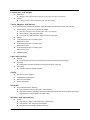
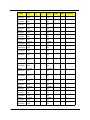
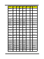
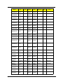
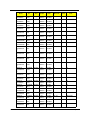
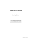
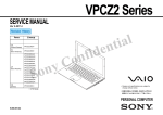
System Block Diagram
5
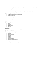
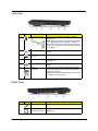
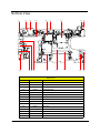
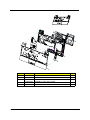
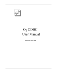
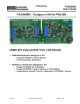
Board Layout
Top View
4
1
2 5
3
9
8 11
6
7 10
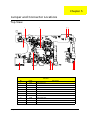
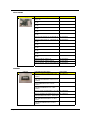
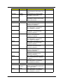
TravelMate 8172/8172Z M/B layout and connector location
TOP view
6
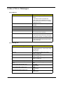
No.
Name
Description
1
CN1
LCM connector
2
CN2
Power
3
CN4
Keyboard connector
4
CN5
Microphone connector
5
CN6
Touch pad connector
6
CN7
Audio cable connector 1
7
CN8
Audio cable connector 2
8
CN9
Card reader slot
9
CN10
Bluetooth connector
10
CN11
Speaker connector
11
CN31
Webcam connector
Chapter 1
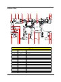
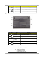
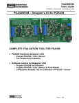
Bottom View
14
17
27
16
18
22 20 19
28
29
13
26
21
15 12
25
23
24
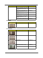
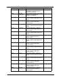
TravelMate 8172/8172Z M/B layout and connector location
Bottom view
Chapter 1
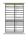
No.
Name
12
CN12
LAN slot
Description
13
CN13
Battery connector
14
CN14
DC-in jack
15
CN15
EZ-Docking slot
16
CN16
SIM Card slot
17
CN17
VGA port
18
CN18
HDD connector
19
CN18
USB slot 1
20
CN20
USB slot 2
21
CN21
DIMM-0
22
CN22
MIC jack
23
CN23
Fan connector
24
CN24
USB slot-3
25
CN25
DIMM-1
26
CN26
3G card slot
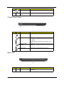
7
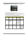
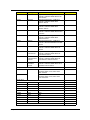
TravelMate 8172/8172Z M/B layout and connector location
Bottom view
8
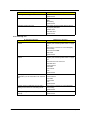
No.
Name
27
CN27
Description
Earphone connector
28
U30
South bridge
29
U32
CPU+ North bridge
Chapter 1
Your Acer Notebook tour
After setting up your computer as illustrated in the Just for Starters... poster, let us show you around your new
Acer notebook.
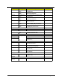
Top View
No.
Chapter 1
Icon
Item
Description
1
Microphones
Stereo internal microphones for sound recording.
2
Display screen
Also called Liquid-Crystal Display (LCD),displays
computer output (Configuration may vary by models).
3
Keyboard
For entering data into your computer.
4
Touchpad
Touch-sensitive pointing device which functions like a
computer mouse.
5
Acer BioProtection
fingerprint reader
The center button serves as the Acer Bio-Protection
fingerprint reader, supporting Pre-Boot Authentication
(PBA) computer protection, Acer FingerLaunch.
6
Click buttons
(left and right)
The left and right buttons function like the left and right
mouse buttons.
9
No.
Icon
Item
Description
7
Power switch
Turns the computer on and off.
8
Acer Crystal Eye
webcam
Web camera for video communication.
Closed Front View
No.
Icon
1
Item
Description
Power indicator
Indicates the computer's power status.
Battery indicator
Indicates the computer's battery status.
1. Charging: The light shows amber when the battery
is charging.
2. Fully charged: The light shows blue when in AC
mode.
Communication
indicator
Indicates the computer’s wireless connectivity device
status.
HDD indicator
Indicates when the hard disk drive is active.
Rear view
No.
1
10
Icon
Item
Battery
Description
Provides power for the computer to be used while
unplugged.
Chapter 1
Left View
No.
Icon
Item
Description
1
Kensington lock slot
Connects to a Kensington-compatible computer
security lock.
NOTE: Wrap the computer security lock cable around
an immovable object such as a table or handle of a
locked drawer. Insert the lock into the notch and turn
the key to secure the lock. Some keyless models are
also available.
2
Ethernet (RJ-45) port
Connects to an Ethernet 10/100/1000- based
network.
3
Acer EasyPort
connector
Connects to Acer EasyPort.
4
Ventilation slots
Enable the computer to stay cool,even after
prolonged use.
5
USB 2.0 ports
Connect to USB 2.0 devices (e.g., USB mouse, USB
camera).
6
Multi-in-1
card reader
Accepts Secure Digital (SD),MultiMediaCard (MMC),
Memory Stick (MS), Memory Stick PRO (MS PRO),
xD-Picture Card (xD).
NOTE: Push to remove/install the card. Only one card
can operate at any given time.
Right View
No.
1
Chapter 1
Icon
Item
Description
Microphone-in jack
Accepts inputs from external microphones.
Headphones/
speaker/line-out jack
Connects to audio line-out devices (e.g., speakers,
headphones).
11
No.
Icon
Item
Description
2
USB 2.0 port
Connects to USB 2.0 devices (e.g., USB mouse, USB
camera).
3
External display
(VGA) port
Connects to a display device (e.g., external monitor,
LCD projector).
4
DC-in jack
Connects to an AC adapter.
Base view
No.
Icon
Item
Battery bay
Houses the computer's battery pack.
2
Battery lock
Locks the battery in position.
3
Hard disk bay
Houses the computer's hard disk (secured with
screws).
4
Acer DASP (Disk
Anti-Shock
Protection)
Protects the hard disk from shocks and bumps.
5
Memory
compartment
Houses the computer's main memory.
6
Battery release latch
Releases the battery for removal.
Environment
12
Description
1
Temperature:
z
Operating: 5°C to 35°C
z
Non-operating: -20°C to 65°C
Humidity (non-condensing):
z
Operating: 20% to 80%
z
Non-operating: 20% to 80%
Chapter 1
Touchpad Basics (with fingerprint reader)
The following items show you how to use the touchpad with Acer Bio-Protection fingerprint reader.
1 2
3
4
Move your finger across the touchpad (1) to move the cursor.
Press the left (2) and right (4) buttons located beneath the touchpad to perform selection and execution
functions. These two buttons are similar to the left and right buttons on a mouse. Tapping on the
touchpad is the same as clicking the left button.
Use Acer Bio-Protection fingerprint reader (3) supporting Acer FingerNav 4-way control function (only
for certain models) to scroll up or down and move left or right a page. This fingerprint reader or button
mimics your cursor pressing on the right scroll bar of Windows applications.
Function
Right Button (4)
Main touchpad (1)
Quickly click
twice.
Tap twice (at the
same speed as
double-clicking a
mouse button).
Select
Click once.
Tap once.
Drag
Click and hold,
then use finger
on the touchpad
to drag the
cursor.
Tap twice (at the
same speed as
double-clicking a
mouse button);
rest your finger
on the touchpad
on the second
tap and drag the
cursor.
Access context
menu
Scroll
Chapter 1
Left Button (2)
Execute
Center button (3)
Click once.
Swipe up/down/
left/right using
Acer FingerNav
4-way control
function(Manufacturing option).
13
Touchpad basics (with two-click buttons)
The following items show you how to use the touchpad with two-click buttons.
Move your finger across the touchpad to move the cursor.
Press the left and right buttons located beneath the touchpad to perform selection and execution
functions. These two buttons are similar to the left and right buttons on a mouse. Tapping on the
touchpad is the same as clicking the left button.
Function
Execute
Left Button
Right Button
Quickly click twice.
Main touchpad
Tap twice (at the
same speed as
double-clicking a
mouse button).
Select
Click once.
Tap once.
Drag
Click and hold, then
use finger on the
touchpad to drag the
cursor.
Tap twice (at the
same speed as
double-clicking a
mouse button); rest
your finger on the
touchpad on the
second tap and drag
the cursor.
Access context menu
Click once.
NOTE: Illustrations for reference only. The exact configuration of your PC depends on the model purchased.
NOTE: When using the touchpad, keep it — and your fingers — dry and clean. The touchpad is sensitive to
finger movement; hence, the lighter the touch, the better the response. Tapping harder will not
increase the touchpad's responsiveness.
NOTE: By default, vertical and horizontal scrolling is enabled on your touchpad. It can be disabled under
Mouse settings in Windows Control Panel.
14
Chapter 1
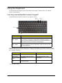
Using the Keyboard
The keyboard has full-sized keys and an embedded numeric keypad*, separate cursor, lock, Windows,
function and special keys.
Lock Keys and embedded numeric keypad*
The keyboard has three lock keys which you can toggle on and off.
F11/
Num Lock
F12/
Scroll Lock
Caps Lock
Fn
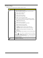
Lock key
Description
Caps Lock
When Caps Lock is on, all alphabetic characters typed are in uppercase.
Num Lock
<Fn> + <F11>*
When Num Lock is on, the embedded keypad is in numeric mode. The
keys function as a calculator (complete with the arithmetic operators +, -,
*, and /). Use this mode when you need to do a lot of numeric data entry. A
better solution would be to connect an external keypad.
Scroll Lock
<Fn> + <F12>
When Scroll Lock is on, the screen moves one line up or down when you
press the up or down arrow keys respectively. Scroll Lock does not work
with some applications.
The embedded numeric keypad functions like a desktop numeric keypad. It is indicated by small characters
located on the upper right corner of the keycaps. To simplify the keyboard legend, cursor-control key symbols
are not printed on the keys.
Desired access
Num Lock on
Number keys on
embedded keypad
Type numbers in a normal manner.
Num Lock off
Cursor-control
keys on embedded
keypad
Hold <Shift> while using cursorcontrol keys.
Hold <Fn> while using cursorcontrol keys.
Main keyboard
keys
Hold <Fn> while typing letters on
embedded keypad.
Type the letters in a normal manner.
* only for certain models
Chapter 1
15
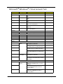
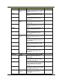
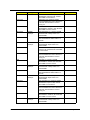
Windows Keys
The keyboard has two keys that perform Windows-specific functions.
Key
Windows
key
Description
Pressed alone, this key has the same effect as clicking on the Windows
Start button; it launches the Start menu.
It can also be used with other keys to provide a variety of functions:
<
> : Open or close the Start menu.
<
> + <D>: Display the desktop.
<
> + <E>: Open Windows Explore.
<
> + <F>: Search for a file or folder.
<
> + <G>: Cycle through Sidebar gadgets.
<
> + <L>: Lock your computer (if you are connected to a network
domain), or switch users (if you're not connected to a network domain).
<
> + <M>: Minimizes all windows.
<
> + <R>: Open the Run dialog box.
<
> + <T>: Cycle through programs on the taskbar.
<
> + <U>: Open Ease of Access Center.
<
> + <X>: Open Windows Mobility Center.
<
> + <BREAK>: Display the System Properties dialog box.
<
> + <SHIFT+M>: Restore minimized windows to the desktop.
<
> + <TAB>: Cycle through programs on the taskbar by using
Windows Flip 3-D.
<
> + <SPACEBAR>: Bring all gadgets to the front and select Windows
Sidebar.
<CTRL> + <
> + <F>: Search for computers (if you are on a network).
<CTRL> + <
> + <TAB>: Use the arrow keys to cycle through programs
on the taskbar by using Windows Flip 3-D.
NOTE: Depending on your edition of Windows Vista, some shortcuts may
not function as described.
Application
key
16
This key has the same effect as clicking the right mouse button; it opens
the application's context menu.
Chapter 1
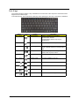
Hot Keys
The computer employs hotkeys or key combinations to access most of the computer's controls like screen
brightness and volume output.
To activate hot keys, press and hold the <Fn> key before pressing the other key in the hotkey combination.
Hotkey
Chapter 1
Icon
Function
Description
<Fn> + <F3>
Communication
Enables / disables the computer’s
communication devices.
(Communication devices may vary by
configuration.)
<Fn> + <F4>
Sleep
Puts the computer in Sleep mode.
<Fn> + <F5>
Display toggle
Switches display output between the display
screen, external monitor (if connected) and
both.
<Fn> + <F6>
Display off
Turns the display screen backlight off to save
power. Press any key to return.
<Fn> + <F7>
Touchpad toggle
Turns the touchpad on and off.
<Fn> + <F8>
Speaker toggle
Turns the speakers on and off.
<Fn> + <
>
Volume up
Increases the sound volume.
<Fn> + <
>
Volume down
Decreases the sound volume.
<Fn> + <
>
Brightness up
Increases the screen brightness.
<Fn> + <
>
Brightness down
Decreases the screen brightness.
17
Using the system utilities
Acer Bio-Protection (only for certain models)
Acer Bio-Protection Fingerprint Solution is a multi-purpose fingerprint software package integrated with the
Microsoft Windows operating system. Utilizing the uniqueness of one's fingerprint, Acer Bio-Protection
Fingerprint Solution incorporates protection against unauthorized access to your computer with centralized
password management via Password Bank; easy music player launching with Acer MusicLaunch*; secure
Internet favorites via Acer MyLaunch*; and fast application/website launching and login with Acer
FingerLaunch. Acer ProfileLaunch** can launch up to three applications/ websites with a single finger swipe.
Acer Bio-Protection Fingerprint Solution also allows you to navigate through web browsers and documents
using Acer FingerNav*. With Acer Bio-Protection Fingerprint Solution, you can now enjoy an extra layer of
protection for your personal computer, as well as the convenience of accessing your daily tasks with a simple
swipe of your finger!
For more information, refer to the Acer Bio-Protection help files.
NOTE:
* Acer ProfileLaunch, MusicLaunch, MyLaunch and FingerNav are only available on select models.
** In models without Acer ProfileLaunch, Acer FingerLaunch can be used to open applications in the Acer
ProfileLaunch icons area; a single finger swipe will launch only one application at a time.
18
Chapter 1
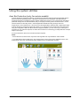
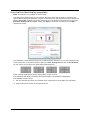
Acer GridVista (dual-display compatible)
NOTE: This feature is only available on certain models.
To enable the dual display feature of your notebook, first ensure that a second display is connected, then,
open the Display Settings properties box using the Control Panel or by right-clicking the Windows desktop and
selecting Personalize. Select the secondary monitor (2) icon in the display box and then click the check box
Extend the desktop onto this monitor. Finally, click Apply to confirm the new settings and click OK to
complete the process.
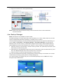
Acer GridVista is a handy utility that offers four pre-defined display settings so you can view multiple windows
on the same screen. To access this function, please go to Start, All Programs and click on Acer GridVista.
You may choose any one of the four display settings indicated below:
Double (vertical), Triple (primary at left), Triple (primary at right), or Quad.
Acer Gridvista is dual-display compatible, allowing two displays to be partitioned independently.
Acer GridVista is imple to set up:
1. Run Acer GridVista and select your preferred screen configuration for each display from the taskbar.
2. Drag and drop each window into the appropriate grid.
Chapter 1
19
3. Enjoy the convenience of a well-organized desktop.
NOTE: Please ensure that the resolution setting of the second monitor is set to the manufacturer's
recommended value.
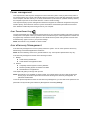
Acer Backup Manager
NOTE: This feature is only available on certain models.
Acer Backup Manager is a simple three-step process that allows you to create backup copies of your entire
system or selected files and folders according to a schedule or as you need to.
To start Acer Backup Manager, press the Acer Backup Manager key above the keyboard. Alternatively, you
can go to Start > All Programs > Acer Backup Manager > Acer Backup Manager. This will open the
Welcome screen; from this screen you will be taken through the three steps to setup scheduled back ups.
Click Continue to proceed to the following screen. Click the + button and follow the onscreen instructions:
1. Select the content you want to back up. The less content you select, the quicker the process will be, but it
will increase your risks of losing data.
2. Select where you want the backup copies to be stored. You will need to select an external drive or your D:
drive; Acer Backup Manager cannot store a backup on the source drive.
3. Select how often you want Acer Backup Manager to create back ups.
Once you have finished these three steps, backups will be created according to the schedule. You can also
create backups manually by pressing the Acer Backup Manager key.
If you wish to change your settings at any time, run Acer Backup Manager from the Start menu and go
through the steps outlined above.
20
Chapter 1
Power management
This computer has a built-in power management unit that monitors system activity. System activity refers to
any activity involving one or more of the following devices: keyboard, mouse, hard disk, peripherals connected
to the computer, and video memory. If no activity is detected for a period of time (called an inactivity timeout),
the computer stops some or all of these devices in order to conserve energy.
This computer employs a power management scheme that supports the advanced configuration and power
interface (ACPI), which allows for maximum power conservation and maximum performance at the same
time. Windows handles all power-saving chores for your computer.
Acer PowerSmart key
The Acer PowerSmart key uses the power-saving features of your computer's graphics sub-system to reduce
overall power consumption. When you press the Acer PowerSmart key, the screen brightness is reduced and
the graphics chip switched to a lower speed; PCI and WLAN switch to power-saving modes. Press the Acer
PowerSmart key again to return to your previous settings.
NOTE: This feature is only available on certain models.
Acer eRecovery Management
Acer eRecovery Management is a tool to quickly restore the system. You can back up/restore the factory
default image, and reinstall applications and drivers.
NOTE: All of the following content is for general reference only. Actual product specifications may vary.
Acer eRecovery Management consists of the following functions:
1. Backup:
z Create Factory Default Disc
z Create Drivers and Applications Disc
2. Restore:
z Completely Restore System to Factory Defaults
z Restore Operating System and Retain User Data
z Reinstall Drivers or Applications
This chapter will guide you through each process.
NOTE: This feature is only available on certain models. For systems that do not have a built-in optical disc
burner, plug in an external optical disc burner before entering Acer eRecovery Management for
optical disc-related tasks.
To use the password protection feature of Acer eRecovery Management, you must first set the password. The
password is set by launching Acer eRecovery Management and clicking Settings.
Chapter 1
21
Burn backup discs
From the Backup page of Acer eRecovery Management, you can burn the factory default image or back up
drivers and applications.
1. Click on Start > All Programs > Acer > Acer eRecovery Management.
2. Acer eRecovery Management opens to the Backup page.
3. Select the type of backup (factory default or drivers and applications) you would like to burn to disc.
4. Follow the instructions on screen to complete the process.
NOTE: Create a factory default image when you want to burn a bootable disc that contains your computer's
entire operating system as it was delivered to you from the factory. If you wish to have a disc that will
allow you to browse the contents and install selected drivers and applications, create a drivers and
application backup instead — this disc will not be bootable.
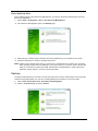
Restore
The restore feature allows you to restore or recover the system from a factory default image or from previously
created CD and DVD backups. You can also reinstall applications and drivers for your Acer system.
1. Click on Start, All Programs, Acer, Acer eRecovery Management.
2. Switch to the Restore page by clicking Restore.
22
Chapter 1
3. You can choose to restore the system from a factory default image or reinstall applications and drivers.
4. Follow the instructions on screen to complete the process.
Restore Windows Vista from backup discs
To restore Windows Vista from your previously burned backup discs, you will need to insert the first backup
disc and enable the F12 Boot Menu via the BIOS Setup Utility.
1. Turn on your computer and insert the first system recovery disc into the optical disc drive. Restart your
computer.
2. During startup when the Acer logo shows, press the F2 key to enter BIOS Setup, where you can set
system parameters.
3. Use the left and right arrow keys to select the Main submenu.
4. Use the up and down arrow keys to select F12 Boot Menu.
5. Use the F5 or F6 key to change F12 Boot Menu to Enabled.
6. Press the ESC key to enter the Exit submenu, press the ENTER key to Exit Saving Changes. Press the
ENTER key again to select Yes. The system will reboot.
7. After rebooting, when the Acer logo shows, press the F12 key to open the Boot Menu. Here you can
select which device to boot from.
8. Use the arrow keys to select the IDE CD, then press the ENTER key. Windows will be installed from the
recovery disc.
9. Insert the second recovery disc when prompted, then follow the onscreen prompts to complete the
restore.
10. Remove the recovery disc from the optical drive once the restore is complete. Do this before rebooting
your computer.
If you prefer to set the boot priority for long-term use, you should select the Boot submenu.
1. Turn on your computer and insert the first system recovery disc into the optical disc drive. Restart your
computer.
2. During startup when the Acer logo shows, press the F2 key to enter BIOS Setup, where you can set
system parameters.
3. Use the left and right arrow keys to select the Boot subme
4. Use the up and down arrow keys to select the IDE CD device.
5. Use the F6 key to move the IDE CD device to the highest boot priority, or use the F5 key to move other
devices to a lower boot priority. Ensure that the IDE CD device is the highest priority.
6. Press the ESC key to enter the Exit submenu, press the ENTER key to Exit Saving Changes. Press the
ENTER key again to select Yes. The system will reboot.
7. When you reboot, Windows will be installed from the recovery disc.
8. Insert the second recovery disc when prompted, then follow the onscreen prompts to complete the
restore.
9. Remove the recovery disc from the optical drive once the restore is complete. Do this before rebooting
your computer.
Chapter 1
23
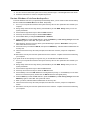
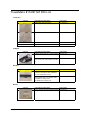
Hardware Specifications and Configurations
Processor
Item
Specification
Type
Core i5-540UM
Description
CPU intel Core i5 540UM 1.2G 18W
L3 Cache
8MB
FSB
1.20GHz
TDP (Thermal)
10W
Socket type
BGA
Second Level Cache
Item
Specification
North Bridge
CPU + GMCH
South Bridge
Ibexpeak-M HM55
System Memory
Item
Specification
Technology
DDR3 1066 / 1333MHz
Base memory
DDR3 SO-DIMM x 1 slot (1024) / 2048 / 4096MB DDR3
SDRAM
Expansion memory
DDR3 SO-DIMM x 1 slot (1024) / 2048 / 4096MB DDR3
SDRAM
Maximum memory size
8GB (Thermal evaluation bsed on 8GB)
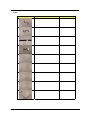
Lan Interface
Item
Specification
Controller (AVAP)
Broadcom BCM57760
SPEED
10 / 100 / 1000Mb/s
Wireless LAN
Item
Specification
Module
Intel PP / CP 3rd WiFi 1x2 / 2x2 / BGN/N
Interface
Mini Card
Antenna
2
Pointing Device
Item
Glide
24
Specification
Multi-touch touch PAD
Chapter 1
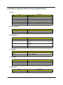
Bluetooth Interface
Item
Specification
Module
FOX_BRM_2046 T60G928.11
Antenna
on board
controller
CSR
Bluetooth module
Internal USB 2.0
Hard Disk Drive Interface
Item
Specification
HDD form factor
9.5 mm high / 12.5 mm high / solid state disks
Media I/F
SATA
IDE Controller
SATA 150 MB/s
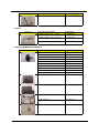
Audio Interface
Item
Sound Codec (AVAP)
Specification
Conexant CX20672-11Z
Internal Speakers
2 (1.5 Watt)
Internal Microphone
Array MIC x 1
Sound Volume
By Hot Key
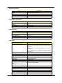
LCD panel
Item
Chapter 1
Specification
Vendor and model name
LED LCD AUO 11.6" WXGA B116XW02 V0 8ms 500:1
LED LCD LPL 11.6" WXGA LP116WH1-TLN1 LF 200nit
8ms 500:1
LED LCD CMO 11.6" WXGA N116B6-L02 C2 LF 200nit
10ms 500:1
LED LCD SAMSUNG 11.6" WXGA LTN116AT03 LF 200nit
16ms 500:1
Screen Diagonal [mm]
293.83
Active Area [mm]
256.125 X 144.0
Pixels H x V
1366x3(RGB) x 768
Pixel Pitch [mm]
0.1875 x 0.1875
Pixel Format
R.G.B. Vertical Stripe
Display Mode
Normally White
White Luminance (ILED=20mA)
[cd/m2]
(Note: ILED is LED current)
200 typ. (5 points average)
170 min. (5 points average)
Luminance Uniformity
1.25 max. (5 points)
Contrast Ratio
500:1 typ
Response Time [ms]
8 typ / 16 Max
Nominal Input Voltage VDD [Volt]
+3.3 typ.
Power Consumption [Watt]
4.0 max. (Include Logic and Blu power)
Weight[Grams]
255g max.
25
Item
Physical Size
Include bracket [mm]
Specification
Min.
Typ.
Max
Length
267.5
268.0
268.5
Width
161.0
161.5
162.0
Thickness
-
-
5.2
Min.
Typ.
Horizontal(Right)
40
45
CR=10(Left)
40
45
Veritical(Upper)
10
15
CR=10(Lower)
30
30
Electrical Interface
1 channel LVDS
Glass Thickness [mm]
0.5
Surface Treatment
Glare, Hardness 3H,
Reflection <4%
Support Color
262K colors ( RGB 6-bit )
Temperature Range
0 to +50
-20 to +60
Operating[oC]
Storage (Non-Operating)[oC]
RoHS Compliance
RoHS Compliance
Viewing Angle [degree]
Brightness
Brightness controlled by Hot Keys
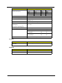
Card Slot
Item
5 in 1 card reader (SD/MMC/MS/
MSPro/xD)
Specification
RTS5128, supported 8GB (test pass)
WebCAM
Item
26
Specification
Module
1.3M
Interface
USB
Chapter 1
Keyboard
Item
Controller
Specification
Acer NT1T
I/O
Item
Specification
Monitor(VGA)
Yes
HDMI
No
USB
3
Stereo Mic-in
1
SPDIF
1
RJ45
1
mini card socket(Full size)
Full mini card (3G) x 1 & Half mini card (SP WLAN) x 1
Button
Item
Specification
Power on/off (with Visiable LED)
1 (mechanical, Blue)
WLAN
None
3G/BT
None
Launch key module(Follow spec)
None
Back up key
None
Power consumption key
None
Volume Control
None
Software
Item
Specification
Operation system
Windows 7
BIOS
Insyde H2O
Power Management
Item
Chapter 1
Specification
Controller
ITE ITE8512F
Interface
LPC
AC adapter (AVAP)
30W
1st Battery (AVAP)
3-cell 2.2Ah
6-cell 4.4Ah
6-cell 5.6Ah
27
LED Status Indicator
Item
Specification
Power Status
1 (Blue / Orange)
1st Battery Status
1 (Blue / Orange)
HDD
1 (Blue)
Caps Lock
1 (Blue)
Num Lock
1 (Blue)
Wireless LAN
1 (Blue / Orange)
Bluetooth
1 (Blue)
Security Features
Item
Specification
Kensington Lock Hole(7.5 mm
diameter)
1
Fingerprint
Optional
TPM
None
FAN
Item
Specification
Not Noise
as low as possible
Number
1
Physical Characteristics
Item
28
Specification
Dimensions
285mm x 206.3mm
Thickness (maximum)
20.2 ~ 29.1mm
Weight (incl 1st Battery & super
multi ODD)
Target < 1.35kg
Chapter 1
Chapter 2
System Utilities
BIOS Setup Utility
The BIOS Setup Utility is a hardware configuration program built into your computer’s BIOS (Basic Input /
Output System).
Your computer is already properly configured and optimized, and you do not need to run this utility. However, if
you encounter configuration problems, you may need to run Setup.Please also refer to Chapter 4
Troubleshooting when problem arises.
To activate the BIOS Utility, press m during POST (when “Press <F2> to enter Setup” message is prompted on
the bottom of screen).
Press m to enter setup. The default parameter of F12 Boot Menu is set to “disabled”. If you want to change
boot device without entering BIOS Setup Utility, please set the parameter to “enabled”.
Press <F12> during POST to enter multi-boot menu. In this menu, user can change boot device without
entering BIOS SETUP Utility.
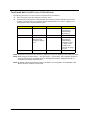
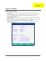
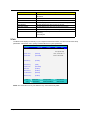
InsydeH2O Setup Utility
Information
Chapter 2
Main
Advanced
Rev. 3.0
Security
Boot
CPU Type:
Genuine Intel( R ) CPU
CPU Speed:
T2300 @ 1.66GHz
IDE 0 Model Name:
ST960821A-(PM)
IDE0 Serial Number:
3LF005DB
ATAPI Model Name:
MATSHITADVD
System BIOS Version:
V1.00
VGA BIOS Version:
ATI V008.050I.0-26.00
Serial Number:
xxxxxxxxxxxxxxxxxxxx (Max: 22 Byte)
Asset Tag Number:
xxxxxxxxxxxxxxxxxxxx (Max: 32 Byte)
Product Name:
xxxxxxxxxxxxxxxxxxxx (Max: 16 Byte)
UUID:
xxxxxxxxxxxxxxxxxxxx (Max: 16 Byte)
Exit
F1 Help
↑↓ Select Item
Esc
←→ Select Menu Enter Select4Sub-Menu F10 Save and Exit
Exit
F5/F6 Change Values
F9
Setup defaults
29
Invoking BIOS Setup
The setup function can only be invoked by pressing F2 when Press <F2> to enter Setup message is prompted
on the bottom of screen during POST.
The setup uses a menu driven interface to allow the user to configure their system. The features are divided
into 5 parts as follows:
Information
Display the system informations.
Main
allows the user to specify standard IBM PC AT system parameters.
Security
Provides security settings of the system.
Boot
Allows the user to specify the boot options.
Exit
Allows the user to save CMOS setting and exit Setup.
NOTE: You can change the value of a parameter if it is enclosed in square brackets. Navigation keys for a
particular menu are shown on the bottom of the screen. Help for parameters are found in the Item
Specific Help part of the screen. Read this carefully when making changes to parameter values.
Please note that system information is subject to different models.
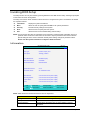
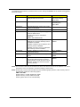
Information
InsydeH2O Setup Utility
Information
Main
Advanced
Rev. 3.0
Security
Boot
CPU Type:
Genuine Intel( R ) CPU
CPU Speed:
T2300 @ 1.66GHz
IDE 0 Model Name:
ST960821A-(PM)
IDE0 Serial Number:
3LF005DB
ATAPI Model Name:
MATSHITADVD
System BIOS Version:
V1.00
VGA BIOS Version:
ATI V008.050I.0-26.00
Serial Number:
xxxxxxxxxxxxxxxxxxxx (Max: 22 Byte)
Asset Tag Number:
xxxxxxxxxxxxxxxxxxxx (Max: 32 Byte)
Product Name:
xxxxxxxxxxxxxxxxxxxx (Max: 16 Byte)
UUID:
xxxxxxxxxxxxxxxxxxxx (Max: 16 Byte)
F1
Help
Esc Exit
Exit
↑↓ Select Item
F5/F6 Change Values
←→ Select Menu
Enter Select4Sub-Menu F10 Save and Exit
F9
Setup defaults
NOTE: Other fields are informational items and are unit dependent.
Parameter
30
Description
CPU Type
This field shows the CPU type of the system.
CPU Speed
This field shows the CPU speed of the system.
IDE0 Model Name
The field shows the Model name of HDD installed on Primary
IDE master.
Chapter 2
Parameter
Description
IDE0 Serial Number
The field shows the Serial number of HDD installed on Primary
IDE master.
ATAPI Model Name
The field shows the Model name of ATAPI.
System BIOS version
Displays system BIOS version.
VGA BIOS Version
This field displays the VGA firmware version of the system.
Serial Number
This field displays the serial number of this unit.
Asset Tag Number
This field displays the asset tag number of the system.
Product Name
This field shows product name of the system.
UUID Number
This will be visible only when an internal LAN device is
presenting.
UUID=32bytes
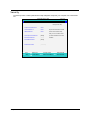
Main
The Main screen displays a summary of your computer hardware information, and also includes basic setup
parameters. It allows the user to specify standard IBM PC AT system parameters.
InsydeH2O Setup Utility
Information
Main
Advanced
Rev. 3.0
Security
Boot
Exit
Item specific Help
System Time:
[09:00:00]
<Tab>, <Shift-Tab>, or
System Date:
[01/01/2003]
<Enter> selects field
Total Memory
[xxxxMB]
Video Memory:
[XMB]
Graphic mode
[Switchable]
Quiet Boot:
[Enabled]
Network boot:
[Enabled]
F12 Boot Menu:
[Disabled]
D2D Recovery:
[Enabled]
F1 Help
↑↓ Select Item
Esc Exit
←→ Select Menu Enter Select4Sub-Menu F10 Save and Exit
F5/F6 Change Values
F9
Setup defaults
NOTE: The screen above is for your reference only. Actual values may differ.
Chapter 2
31
The table below describes the parameters in this screen. Settings in boldface are the default and suggested
parameter settings.
Parameter
Description
Format/Option
System Time
Sets the system time. The hours are
displayed with 24-hour format.
Format: HH:MM:SS
(hour:minute:second)
System Time
System Date
Sets the system date.
Format: MM/DD/YYYY
(month/day/year)
System Date
Total Memory
This field reports the memory size of total
memory in the system.
Video Memor
Shows the Video memory size.
Graphic mode
The following define the options of graphic
mode for different skus:
For Mux_less projects: Switchable/
Integrated
Others: Switchable/Discrete
Quiet Boot
Determines if Customer Logo will be
displayed or not; shows Summary Screen
is disabled or enabled.
Enabled: Customer Logo is displayed, and
Summary Screen is disabled.
Disabled: Customer Logo is not displayed,
and Summary Screen is enabled.
Option: Enabled or
Disabled
Network Boot
Enables, disables the system boot from
LAN (remote server).
Option: Enabled or
Disabled
F12 Boot Menu
Enables, disables Boot Menu during
POST.
Option: Disabled or
Enabled
D2D Recovery
Enables, disables D2D Recovery function.
The function allows the user to create a
hidden partition on hard disc drive to store
operation system and restore the system
to factory defaults.
Option: Enabled or
Disabled
NOTE: The sub-items under each device will not be shown if the device control is set to disable or auto. This is
because the user is not allowed to control the settings in these cases.
NOTE: Please refer to Acer’s VGA TAG table.For Intel switchable graphic platforms, Video memory refers to
the dedicated VRAM size of discrete graphics.
AMD or NV UMA:
System memory >=512M, VRAM set to 256M
System memory < 512M, VRAM set to 64M
Others: (please refer to Acer VGA tAG table)
32
Chapter 2
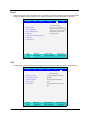
Security
The Security screen contains parameters that help safeguard and protect your computer from unauthorized
use.
InsydeH2O Setup Utility
Information.
Main
Advanced
Rev. 3.0
Security
Boot
Exit
Item specific Help
Supervisor Password Is
Clear
User Password Is
Clear
Supervisor Password controls
HDD Password
Clear
access to the whole setup
utility. It can be used to boot
Set Supervisor Password
[Enter]
up when Password on boot is
Set User Password
[Enter]
enabled.
Set HDD Password
[Enter]
Password on Boot:
[Disabled]
F1
Esc
Chapter 2
Help
Exit
↑↓ Select Item
F5/F6 Change Values
F9
Setup defaults
←→ Select Menu
Enter Select4Sub-Menu
F10
Save and Exit
33
The table below describes the parameters in this screen. Settings in boldface are the default and suggested
parameter settings.
Parameter
Description
Option
Supervisor Password
is
Shows the setting of the Supervisor
password.
Clear or Set
User Password is
Shows the setting of the user password.
Clear or Set
HDD Password is
Shows the setting of HDD password.
Clear or Set
Set Supervisor
Password
Press Enter to set the supervisor password.
When set, this password protects the BIOS
Setup Utility from unauthorized access. The
user can not enter the Setup menu and
change he value of parameters.
Set User Password
Press Enter to set the user password.
When user password is set, this password
protects the BIOS Setup Utility from
unauthorized access.
The user can enter Setup menu only and
does not have right to change the value of
parameters.
Set Hdd Passwor
Press Enter to set the Hdd password.
When Hdd password is set, this
password protects the Hdd . Other
user can’t steal information.
Password on Boot
Defines whether a password is required or
not while the events defined in this group
happened. The following sub-options are all
requires the Supervisor password for
changes and should be grayed out if the
user password was used to enter setup.
Disabled or Enabled
NOTE: When you are prompted to enter a password, you have three tries before the system halts. Don’t forget
your password. If you forget your password, you may have to return your notebook computer to your
dealer to reset it.
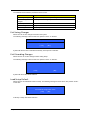
Set Supervisor Password
While these fields are highlighted and press ”Enter” , a window similar to the following is shown:
Set Supervisor Password
Enter New Password
[
]
Confirm New Password
[
]
If there is an old password then setup will prompt with the following window instead and a current password
will be required to be entered at first:
Set Supervisor Password
34
Enter current password
[
]
Enter New Password
[
]
Confirm New Password
[
]
Chapter 2
User can now type password in field “ Enter New Password“, and
re-enter password in field “Confirm New Password“ for verification.
Set Supervisor Password
Enter current password
[
]
Enter New Password
[
]
Confirm New Password
[
]
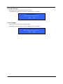
If the verification is OK:
Setup Notice
Changes have been saved.
[ continue]
The password setting is complete after user presses enter.
Setup Warning
Invalid password
Re-enter Password
[ continue]
If the new password and confirm new password strings do not match:
Setup Warning
Password do not match
Re-enter Password
The format of the password is as follows:
Password Max Length : 8 characters.
Characters List Table:
Chapter 2
A-Z
Alphabets A through Z (Not Case Sensitive)
0-9
Numerical Characters.
-
Dash
=
Equal Sign
[
Left Bracket
]
Right Bracket
.
Period
,
Comma
;
Semi-colon
/
Slash
\
Back-slash
35
Boot
This menu allows the user to decide the order of boot devices to load the operating system. Bootable devices
includes the distette drive in module bay, the onboard hard disk drive and the CD-ROM in module bay.
InsydeH2O Setup Utility
Information
Main
Advanced
Rev. 3.0
Security
Boot
Exit
Item specific Help
Boot priority order:
Use <↑> or <↓> to select a
device, then press <F6> to move
it up the List, or <F5> to move it
1. IDE 0: ST960821A
2: IDE 1: MATSHITADVD
down the list. Press <Esc> to
escape the menu
3: USB FDD:
4. Network Boot: Realtek Boot Agent
5. USB HDD:
6. USB CDROM:
F1
Help
Esc
Exit
↑↓ Select Item
F5/F6 Change Values
F9
←→ Select Menu
Enter Select4Sub-Menu
F10
Setup defaults
Save and Exit
Exit
The Exit screen contains parameters that help safeguard and protect your computer from unauthorized use.
InsydeH2O Setup Utility
Information
Main
Advanced
Security
Rev. 3.0
Boot
Exit
Item specific Help
Exit Saving Changes
Exit System Setup and save your
Exit Discarding Changes
Changes
Load Setup Defaults
Exit utility without saving Setup
Discard changes
Data
Save changes
Load default values for all SETUP
item.
F1
Esc
36
Help
Exit
↑↓ Select Item
F5/F6 Change Values
F9
←→ Select Menu
Enter Select4Sub-Menu
F10
Setup defaults
Save and Exit
Chapter 2
The table below describes the parameters in this screen.
Parameter
Description
Exit Saving Changes
Exit System Setup and save your changes to CMOS.
Exit Discarding
Changes
Exit utility without saving setup data to CMOS.
Load Setup Default
Load default values for all SETUP item.
Discard Changes
Load previous values from CMOS for all SETUP items.
Save Changes
Save Setup Data to CMOS.
Exit Saving Changes
Allows the user to save changes and reboot the system.
The following message is shown when user presses “Enter” on the item
Setup Confirmation
Save configuration changes and exit now
[ Yes]
[No]
System will reboot if Yes is selected and will stay in Setup if No is selected..
Exit Discarding Changes
Allows the user to not save changes before exiting Setup.
The following message is shown when user presses “Enter” on this item.
Exit discarding changes?
[Yes]
[No]
System will reboot after either selection.
Load Setup Default
Allows the user to load default values in Setup. The following message is shown when user presses “Enter”
on this item:.
Setup Confirmation
Load default configuration now?
[ Yes]
[No]
It still stay in Setup after either selection.
Chapter 2
37
Discard Changes
Allows the user to discard previous changes in Setup.
The following message is shown when user presses “Enter” on this item:
Setup Confirmation
Load previous configuration now?
[ Yes]
[No]
Save Changes
Allows the user to save current changes in Setup.
The following message is shown when user presses “Enter” on this item:
Setup Confirmation
Save configuration changes now?
[ Yes]
38
[No]
Chapter 2
BIOS Flash Utility
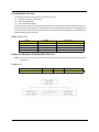
The BIOS flash memory update is required for the following conditions:
New versions of system programs
New features or options
Restore a BIOS when it becomes corrupted.
Use the Phlash utility to update the system BIOS flash ROM.
NOTE: If you do not have a crisis recovery diskette at hand, then you should create a Crisis Recovery
Diskette before you use the Phlash utility.
NOTE: Do not install memory-related drivers (XMS, EMS, DPMI) when you use the Phlash.
NOTE: Please use the AC adaptor power supply when you run the Phlash utility. If the battery pack does not
contain enough power to finish BIOS flash, you may not boot the system because the BIOS is not
completely loaded.
Fellow the steps below to run the Phlash.
1. Prepare a bootable diskette.
2. Copy the flash utilities to the bootable diskette.
3. Then boot the system from the bootable diskette. The flash utility has auto-execution function.
Chapter 2
39
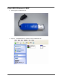
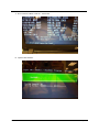
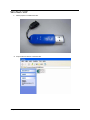
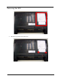
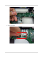
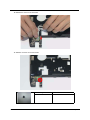
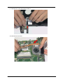
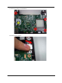
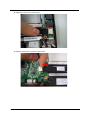
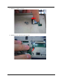
DOS flash BIOS SOP
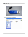
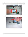
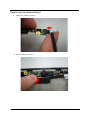
1. Please prepare a bootable flash disk.
2. Unzip the “BIOS”and leave the DOS file in the bootable flash disk.
40
Chapter 2
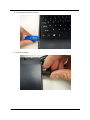
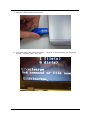
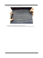
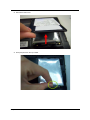
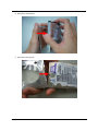
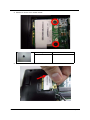
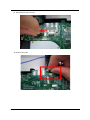
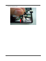
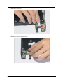
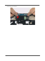
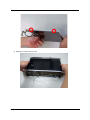
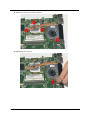
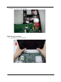
3. Insert the flash disk with the unzip file.
4. Connect the adapter.
Chapter 2
41
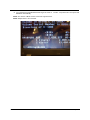
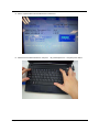
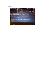
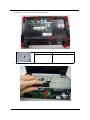
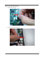
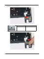
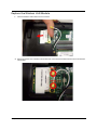
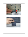
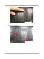
5. Log in the DOS by bootable flash disk and type the name of “exe file”and press Enter. The system will
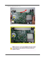
flash BIOS automatically.
NOTE: The version of BIOS must be newer than original version.
NOTE: Adapter have to be connected.
42
Chapter 2
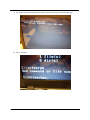
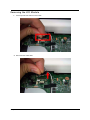
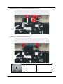
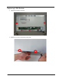
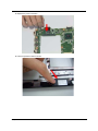
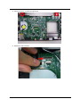
Clean BIOS Password SOP
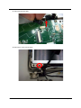
1. Please prepare a bootable flash disk.
2. Unzip the “CleanBIOSPassword” and leave it in the bootable flash disk.
Chapter 2
43
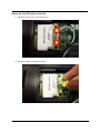
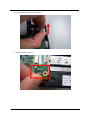
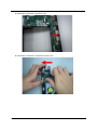
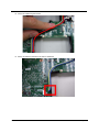
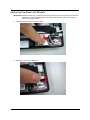
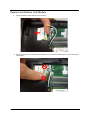
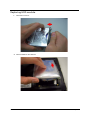
3. Insert the flash disk with the unzip file.
4. Connect the adapter.
44
Chapter 2
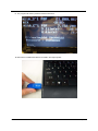
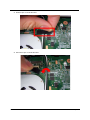
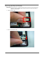
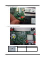
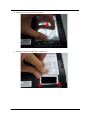
5. Set the supervisor BIOS and enable Power on Password.
6. Please insert bootable USB device, and press “alt gr+backspace+Esc”and press power button.
Chapter 2
45
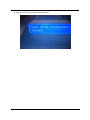
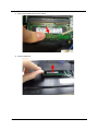
7. The system will automatically ignore the power on password and log in the bootable flash disk.
8. Insert “clearbpw” .
46
Chapter 2
9. When the screen show “Clear the SU PWs completely” means the BIOS password removed
completely.
Chapter 2
47
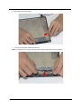
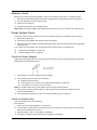
Clean HDD Password SOP
1. Please prepare a bootable flash disk.
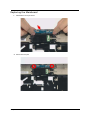
2. Unzip the “CleanHDDPassword” and leave it in the bootable flash disk.
48
Chapter 2
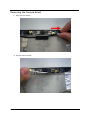
3. Insert the flash disk with the unzip file.
4. Connect the adapter.
Chapter 2
49
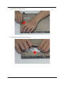
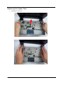
5. After inserting the wrong HDD password three times. The system will show select item screen.
6. Memorize the error code behind the “Enter Unlock Password” .
NOTE: the number will be created by system in disorder.
50
Chapter 2
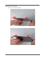
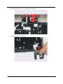
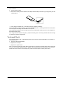
7. Remove the disk and insert it in other system.
8. Log in DOS mode in other system. Execute the “Unlockhd”in the bootable flash disk by insert the
keyword: “unlockhd+ space + error code” .
Chapter 2
51
9. The program will create a password. Please memorize it.
10. Remove the bootable flash disk and re-install in the original system.
52
Chapter 2
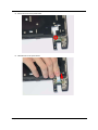
11. Enter the password and the HDD lock will be released.
Chapter 2
53
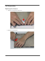
Crisis Disk SOP
1. Please prepare a bootable flash disk.
2. Unzip the “Crisis disk” and leave it in the bootable flash disk.
54
Chapter 2
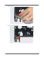
3. Insert the flash disk with the unzip file.
4. Connect the adapter.
Chapter 2
55
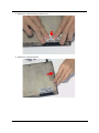
5. Press “Fn+ESC+Power” to power on the system.
6. The system will automatically power on after several minutes.
7. Please use normal BIOS flash procedure to flash BIOS again when the machine be rescued.
56
Chapter 2
DMI Utility SOP
1. Please prepare a bootable flash disk.
2. Unzip the “dmi174”and leave it in the bootable flash disk.
Chapter 2
57
3. Insert the flash disk with the unzip file.
4. Connect the adapter.
58
Chapter 2
5. Log in dos mode and type “dmi174r” to execute the program.
6. Activate the program.
Chapter 2
59
7. Type “DMI174 /?” can check all of the function of DMI.
60
Chapter 2
LAN EEPROM Utility SOP
1. Please prepare a bootable flash disk.
2. Unzip the MAC.zip and leave it in the bootable flash disk.
Chapter 2
61
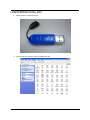
3. Insert the flash disk with the unzip file.
4. Connect the adapter.
62
Chapter 2
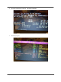
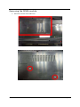
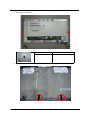
5. Power on the system and press F2 to log in the BIOS. Select the USB HDD to the first priority.
6. Save the BIOS setting, the system will reboot automatically and log in DOS.
Chapter 2
63
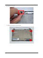
7. Go in to the file of MAC. Insert the “ßmacin.bat” .
8. Input the MAC address.
64
Chapter 2
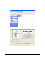
Winflash SOP
1. Please prepare a bootable flash disk.
2. Unzip the file and leave it in the flash disk.
Chapter 2
65
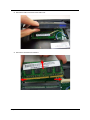
3. Insert the flash disk with the unzip file.
4. Connect the adapter.
66
Chapter 2
5. Double click the Winflash tool and begin to flash BIOS.
NOTE: The version of BIOS must be newer than original version.
NOTE: Adapter have to be connected.
Chapter 2
67
68
Chapter 2
Chapter 3
Machine Disassembly and Replacement
Disassembly Requirements
To disassemble the computer, you need the following tools:
Wrist grounding strap and conductive mat for preventing electrostatic discharge
Flat screwdriver
Philips screwdriver
Plastic flat screwdriver
Plastic tweezers
NOTE: The screws for the different components vary in size. During the disassembly process, group the
screws with the corresponding components to avoid mismatch when putting back the components
Related Information
The product previews seen in the disassembly procedures may not represent the final product color or
configuration.
IMPORTANT: Cable paths and positioning may not represent the actual model. During the removal and
replacement of components, ensure all available cable channels and clips are used and that the
cables are replaced in the same postion.
Replacement Requirements
NOTE: Cabling and components require adhesive to be applied during the replacement and reassembly
process.
NOTE: During manufacture a cyanoacrylate glue is used provided by Holdtite Adhesives LTD. This is not a
specified requirement. The reassembler is free to select an alternative appropriate adhesive.
Chapter 3
69
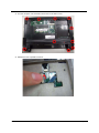
Pre-disassembly Instructions
Before proceeding with the disassembly procedure, make sure that you do the following:
1. Turn off the power to the system and all peripherals.
2. Unplug the AC adapter and all power and signal cables from the system.
3. Place the system on a flat, stable surface.
70
Chapter 3
Disassemble Process
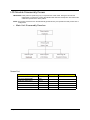
The disassembly process is divided into the following sections:
External components disassembly
Main unit disassembly
LCD module disassembly
The flowcharts provided in the succeeding disassembly sections illustrate the entire disassembly sequence.
Observe the order of the sequence to avoid damage to any of the hardware components. For example, if you
want to remove the Mainboard, you must first remove the Keyboard, and LCD Module then disassemble the
inside assembly frame in that order.
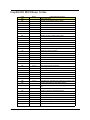
Main Screw List
Screw
Quantity
M2.5*4L
12
M2*6L
11
M2*3
7
M2*2.5
4
Acer part no
External Module Disassembly Process
NOTE: The product previews seen in the disassembly procedures may not represent the final product color or
configuration.
Screw List
Step
Wireless Module Disassembly
Chapter 3
Screw
M2.5*4L
Quantity
part no
2
71
Removing the Battery Pack
1. Turn the computer over.
2. Slide the battery lock/unlock latch to the unlock position.
72
Chapter 3
3. Slide and hold the battery to the release position (1) and remove the battery from the main unit (2).
Chapter 3
73
Removing the HDD
1. Remove two (2) screws on the HDD cover.
74
Chapter 3
2. Remove the HDD cover.
3. Grasp the pull tab on the top of HDD.
Chapter 3
75
4. Lift the HDD out of lower case.
5. Remove the HDD connector.
76
Chapter 3
6. Remove the HDD bracket.
7. Remove the HDD pocket.
Chapter 3
77
Removing the DIMM module
1. Remove two screws on the RAM cover.
78
Chapter 3
2. Remove the RAM cover.Remove the RAM cover.
3. Remove the first RAM from RAM slot.
Chapter 3
79
4. Remove the second RAM from RAM slot.
80
Chapter 3
Remove the Wireless module
1. Notice the antenna color on the wireless card.
2. Release the cable of the wireless module.
Chapter 3
81
3. Release two screws on the wireless module.
Type
M2.5*4
Number
2
4. Remove wireless module.
82
Chapter 3
LCD Module Disassembly Process
IMPORTANT: Cable paths and positioning may not represent the actual model. During the removal and
replacement of components, ensure all available cable channels and clips are used and that the
cables are replaced in the same position.
NOTE: The product previews seen in the disassembly procedures may not represent the final product color or
configuration.
1.
Main Unit Disassembly Flowchar.
Screw List
Step
Upper Cover Disassembly
Chapter 3
Screw
M2.5*6L
Quantity
part no
2
Lower Cover Disassembly
M2*6L
9
LCD Module Disassembly
M2.5*4L
2
Power bracket Disassembly
M2*3L
1
Mainboard Disassembly
M2*3L
4
Mainboard Disassembly
M2.5*4L
4
83
Removing the keyboard
1. Use tool to disconnect four latches which hold the keyboard.
2. Gently pry up the keyboard.
84
Chapter 3
3. Carefully flip the keyboard over.
4. Unlock the keyboard FFC.
Chapter 3
85
5. Disconnect the keyboard FFC.
86
Chapter 3
Removing the Upper Case
1. Unlock the touch pad FFC.
2. Disconnect the Touch Pad FFC.
Chapter 3
87
3. Unlock the power board FFC.
4. Disconnect the power board FFC.
88
Chapter 3
5. Remove two screws on the topper case.
Type
M2*6
Chapter 3
Number
2
89
6. Remove all of the screws on the back of the notebook.
Type
M2*6
Number
9
7. Remove the upper case.
90
Chapter 3
Removing the LCD Module
1. Use the pull tab and Grab the LVDS cable.
2. Disconnect the LVDS cable.
Chapter 3
91
3. Grab the tape on the WLAN cable.
4. Remove the tape on the WLAN cable.
92
Chapter 3
5. Release WLAN cable.
6. Remove 3G tape with the same method.
Chapter 3
93
7. Release the 3G cable.
8. Grab the CCD connector.
94
Chapter 3
9. Disconnect the CCD connector.
10. Grab the MIC cable.
Chapter 3
95
11. Disconnect the MIC cable.
12. Remove the screw from left hinge.
96
Chapter 3
13. Remove the screws from right hinge.
Type
M2.5*4
Number
2
14. Remove the LCD module from the chassis
CAUTION: Make sure all cables are pulled back and away from the device to avoid damage during removal.
Chapter 3
97
Removing the Bluetooth Module
IMPORTANT: Bluetooth Module may not represent the actual model. During the removal and replacement of
components, ensure all available cable channels and clips are used and that the cables are
replaced in the same position.
1. Grab the Bluetooth cable.
2. Disconnect the Bluetooth cable.
98
Chapter 3
3. Remove the Bluetooth module.
Chapter 3
99
Removing the Mainboard
1. Disconnect the Audio cable.
2. Disconnect another side of Audio cable.
100
Chapter 3
3. Remove the audio cable.
4. Remove the screws on the power bracket.
Type
M2*3
Chapter 3
Number
1
101
5. Lift the power bracket from the mainboard.
6. Grab the speaker connector.
102
Chapter 3
7. Remove the speaker connector.
8. Remove four screws on the mainboard.
Type
M2*3
Chapter 3
Number
1
103
9. Remove the Mainboard from button case.
104
Chapter 3
10. Remove speaker module.
11. Grab the speaker module and remove it carefully.
Chapter 3
105
12. Disassemble the power connection.
13. Disassemble fan connector.
106
Chapter 3
14. Release four screws on the thermal module.
15. Remove thermal module.
Chapter 3
107
16. Release the connector of LED board.
17. Release one screw on the LED board.
Type
M2.5*4
108
Number
1
Chapter 3
18. Remove the LED board.
19. Release the connector of power board.
Chapter 3
109
20. Release the screw on the power board.
Type
M2.5*4
Number
1
21. Remove the power board.
110
Chapter 3
22. Release the connector of touch pad board and release the FFC on it.
23. Remove two screws on the touch pad board.
Type
M2.5*4
Chapter 3
Number
2
111
24. Remove the touch pad board.
112
Chapter 3
LCD Module Disassembly Process
IMPORTANT: Cable paths and positioning may not represent the actual model. During the removal
andreplacement of components, ensure all available cable channels and clips are used and that
the cables are replaced in the same position.
NOTE: The product previews seen in the disassembly procedures may not represent the final product color or
configuration.
LCD Module Disassembly Flowchart
Screw List
Step
Chapter 3
Screw
Quantity
LCD Bazel Disassembly
M2.5*4L
2
LCD Panel Disassembly(Down)
M2.5*4L
2
LCD Panel Disassembly(Up)
M2*3L
2
Hinge Disassembly
M2*2.5L
4
part no
113
Removing the Mainboard
1. Use the tweezers to remove the gasket on the bazel.
Type
M2.5*4
Number
2
2. Remove two screws under the gaskets.
114
Chapter 3
3. Pry the bezel away from the top-center and then work around until the entire bezel is detached.
4. Remove the bezel from LCD module.
Chapter 3
115
5. Remove four screws on the corner of LCM.
Type
116
Number
M2.5*4
2
M2*3
1
Chapter 3
6. Lift the panel out.
Chapter 3
117
Removing the Camera Board
1. Disconnect the webcam.
2. Remove webcam module.
118
Chapter 3
Remove the Antennas
1. Release four screws from the LCD bracket.
Chapter 3
119
2. Remove the LCD bracket.
Type
M2*2.5
Number
4
3. Remove the two tapes on the microphone cable.
120
Chapter 3
4. Remove the microphone.
5. Remove the three tapes on the antenna cable.
Chapter 3
121
6. Remove the microphone cable.
7.
Remove the LAN black antenna aluminum foil.
NOTE: The aluminum foil only use one time. Please prepare new replacement for assemble.
122
Chapter 3
8. Remove the LAN white antenna.
9. Remove the LAN white antenna aluminum foil.
Chapter 3
123
LCD Reassembly
Replacing the Antenna
1. Replace the LAN white antenna aluminum foil.
2. Replace the LAN white antenna.
124
Chapter 3
3. Replace the LAN black antenna aluminum foil.
4. Replace the LAN black antenna.
Chapter 3
125
5. Replace the microphone cable.
6. Replace the three tapes on the antenna cable.
126
Chapter 3
7. Lay the microphone cable in the LCD cover.
8. Replace the microphone.
Chapter 3
127
Replacing the Camera Board
1. Replace the webcam connector.
2. Place the webcam in the slot.
128
Chapter 3
Replace the Wireless LAN Module
1. Insert the wireless LAN module into the connector.
2. Fasten two screws on the wireless LAN module and connect black and white antenna line to the wireless
LAN module.
Chapter 3
129
Replacing LCM Module
1. Replace the bracket to the panel.
2. Replace four screws on the bracket of the panel.
130
Chapter 3
3. Replace the panel on the top case.
Chapter 3
131
4. Fasten four screws on the panel.
5. Place the bezel hinge covers over the hinges.Ensure the cables are correctly exiting the hinges.
132
Chapter 3
6. Press down on the top middle edge of the bezel to engage the locking clips.
7. Press down on the bezel edge working simultaneously around the edges to the bottom.
Chapter 3
133
8. Replace the two screws on the panel.
9. Replace two gaskets on the screws of panel.
134
Chapter 3
Replacing the Mainboard
1. Assemble the touch pad board.
2. Fasten the touch pad.
Chapter 3
135
3. Install the three FFCs on the Touch pad board and stable it.
4. Install the power board on the slot.
136
Chapter 3
5. Fasten the screw of the power board.
6. Install the FFC to the power board.
Chapter 3
137
7. Install the LED board.
8. Fasten the screw of the LED board.
138
Chapter 3
9. Install the FFC on the LED board and stable it..
10. Install the thermal module.
Chapter 3
139
11. Fasten four screws on the thermal module.
12. Replace the fan connector.
140
Chapter 3
13. Replace the power connection.
14. Insert the speaker module in the slot.
Chapter 3
141
15. Assemble the mainboard to the bottom case.
16. Assemble the mainboard to the left side of bottom case.
142
Chapter 3
17. Fasten four screws on the mainboard.
18. Insert the power bracket.
Chapter 3
143
19. Fasten one screw on the power bracket.
Replacing the Panel
1. Assemble the panel to the mainboard.
144
Chapter 3
2. Fasten two screws on the left and right hinge.
3. Replace the CCD connector.
Chapter 3
145
4. Let the antenna cable along the red line and put in the hole beside the thermal module.
5. Stick the tape on the cable in order to stable it.
146
Chapter 3
6. Replace the LVDS cable.
7. Replace the MIC cable.
Chapter 3
147
8. Let the 3G cable along the red line.
9. Put the 3G cable into the hole in the side of mainboard.
148
Chapter 3
10. Add two tapes on the 3G cable.
11. Assemble the speaker connector.
Chapter 3
149
12. Replace the connection of audio board.
13. Replace another side connection of Audio board.
150
Chapter 3
Replacing the Bluetooth Module
IMPORTANT: Bluetooth Module may not represent the actual model. During the removal and replacement of
components, ensure all available cable channels and clips are used and that the cables are
replaced in the same position.
1. Assemble the Bluetooth device into the main.
2. Replace the connection of Bluetooth.
Chapter 3
151
Replacing the Upper Case
1. Assemble the upper case.
152
Chapter 3
2. Fasten two screws on the upper case.
Chapter 3
153
3. Turn the computer over and fasten nine screws on the button cover.
4. Release the lock of speaker connector.
154
Chapter 3
5. Replace the speaker connection.
6. Release the lock of the touch pad connection.
Chapter 3
155
7. Connect the touch pad connection..
Replacing the keyboard
1. Release the lock of keyboard connection.
156
Chapter 3
2. Connect the lock of keyboard connection.
3. Turn the keyboard over and insert the bottom edge in first then push to down ensure the five latches
across the top are fully secured.
Chapter 3
157
Replace the Wireless LAN Module
1. Insert the wireless LAN module into the connector.
2. Fasten two screws on the wireless LAN module and connect black and white antenna line to the wireless
LAN module.
158
Chapter 3
Replace the DIMM module
1. Slide the DIMM module into the connector.
2. Press down until the locking springs click into place.
Chapter 3
159
3. Insert another DIMM with the same method.
4. Insert the RAM door.
160
Chapter 3
5. Press down the RAM door.
6. Fasten two screws on the RAM door.
Chapter 3
161
Replacing HDD module
1. Insert HDD connector.
2. Insert the HDD into the HDD slot.
162
Chapter 3
3. Press down the HDD and make sure it stable.
4. Replace the HDD cover and fasten two screws on it.
Chapter 3
163
Replacing the battery
1. Insert the battery carefully.
2. Lock the battery lock.
164
Chapter 3
Chapter 4
Troubleshooting
Use the following procedure as a guide for computer problems.
NOTE: The diagnostic tests are intended to test only Acer products. Non-Acer products, prototype cards, or
modified options can give false errors and invalid system responses.
1. Obtain the failing symptoms in as much detail as possible.
2. Verify the symptoms by attempting to re-create the failure by running the diagnostic test or by repeating
the same operation.
3. Use the following table with the verified symptom to determine which page to go to.
4. If any problem occurs, you can perform visual inspection before you follow this chapter’s instructions.You
can check the following:
power cords are properly connected and secured;
there are no obvious shorts or opens;
there are no obviously burned or heated components;
all components appera normal.
5. Use the following table with the verified symptom to determine which page to go to.
Symptoms (Verified)
Chapter 4
Go To
Power failure. (The power indicator does not
go on or stay on.)
“Power System Check” on page 167.
POST does not complete. No beep or error
codes are indicated.
“Power-On Self-Test (POST) Error Message”
on page 169.
“Undetermined Problems” on page 182.
POST detects an error and displayed
messages on screen.
“Error Message List” on page 170.
Other symptoms (i.e. LCD display problems or
others).
“Power-On Self-Test (POST) Error Message”
on page 169.
Symptoms cannot be re-created (intermittent
problems).
Use the customer-reported symptoms and go
to “Power-On Self-Test (POST) Error
Message” on page 169.
“Intermittent Problems” on page 181.
“Undetermined Problems” on page 182.
165
System Check Procedures
External Diskette Drive Check
Do the following to isolate the problem to a controller, driver, or diskette. A write-enabled, diagnostic diskette is
required.
NOTE: Make sure that the diskette does not have more than one label attached to it. Multiple labels can cause
damage to the drive or cause the drive to fail.
Do the following to select the test device.
1. Boot from the diagnostics diskette and start the diagnostics program.
2. See if FDD Test is passed as the program runs to FDD Test.
3. Follow the instructions in the message window.
If an error occurs with the internal diskette drive, reconnect the diskette connector on the system board.
If the error still remains:
1. Reconnect the external diskette drive/DVD-ROM module.
2. Replace the external diskette drive/CD-ROM module.
3. Replace the main board.
External CD-ROM Drive Check
Do the following to isolate the problem to a controller, drive, or CD-ROM. Make sure that the CD-ROM does
not have any label attached to it. The label can cause damage to the drive or can cause the drive to fail.
Do the following to select the test device:
1. Boot from the diagnostics diskette and start the diagnostics program.
2. See if CD-ROM Test is passed when the program runs to CD-ROM Test.
3. Follow the instructions in the message window.
If an error occurs, reconnect the connector on the System board. If the error still remains:
1. Reconnect the external diskette drive/CD-ROM module.
2. Replace the external diskette drive/CD-ROM module.
3. Replace the main board.
Keyboard or Auxiliary Input Device Check
Remove the external keyboard if the internal keyboard is to be tested.
If the internal keyboard does not work or an unexpected character appears, make sure that the flexible cable
extending from the keyboard is correctly seated in the connector on the system board.
If the keyboard cable connection is correct, run the Keyboard Test.
If the tests detect a keyboard problem, do the following one at a time to correct the problem. Do not replace a
non-defective FRU:
1. Reconnect the keyboard cables.
2. Replace the keyboard.
3. Replace the main board.
The following auxiliary input devices are supported by this computer:
Numeric keypad
External keyboard
If any of these devices do not work, reconnect the cable connector and repeat the failing operation.
166
Chapter 4
Memory check
Memory errors might stop system operations, show error messages on the screen, or hang the system.
1. Boot from the diagnostics diskette and start the doagmpstotics program (please refer to main board.)
2. Go to the diagnostic memory in the test items.
3. Press F2 in the test items.
4. Follow the instructions in the message window.
NOTE: Make sure that the DIMM is fully installed into the connector. A loose connection can cause an error.
Power System Check
To verify the symptom of the problem, power on the computer using each of the following power sources:
1. Remove the battery pack.
2. Connect the power adapter and check that power is supplied.
3. Disconnect the power adapter and install the charged battery pack; then check that power is supplied by
the battery pack.
If you suspect a power problem, see the appropriate power supply check in the following list:
“Check the Power Adapter” on page 167
“Check the Battery Pack” on page 167
Check the Power Adapter
Unplug the power adapter cable from the computer and measure the output voltage at the plug of the power
adapter cable. See the following figure:
Pin 1: +19 to +20.5V
Pin 2: 0V, Ground
1. If the voltage is not correct, replace the power adapter.
2. If the voltage is within the range, do the following:
z Replace the System board.
z If the problem is not corrected, see “Undetermined Problems” on page 182.
z If the voltage is not correct, go to the next step.
NOTE: An audible noise from the power adapter does not always indicate a defect.
3. If the power-on indicator does not light up, check the power cord of the power adapter for correct
continuity and installation.
4. If the operational charge does not work, see “Check the Battery Pack” on page 167.
Check the Battery Pack
To check the battery pack, do the following:
From Software:
1. Check out the Power Management in control Panel.
2. In Power Meter, confirm that if the parameters shown in the screen for Current Power Source and Total
Battery Power Remaining are correct.
3. Repeat the steps 1 and 2, for both battery and adapter.
4. This helps you identify first the problem is on recharging or discharging.
Chapter 4
167
From Hardware:
1. Power off the computer.
2. Remove the battery pack and measure the voltage between battery terminals 1(+) and 6(ground). See the
following figure.
3. If the voltage is still less than 7.5 Vdc after recharging, replace the battery.
To check the battery charge operation, use a discharged battery pack or a battery pack that has less than 50%
of the total power remaining when installed in the computer.
If the battery status indicator does not light up, remove the battery pack and let it return to room temperature.
Re-install the battery pack.
If the charge indicator still does not light up, replace the battery pack. If the charge indicator still does not light
up, replace the DC/DC charger board.
Touchpad Check
If the touchpad doesn’t work, do the following actions one at a time to correct the problem. Do not replace a
non-defective FRU:
1. Reconnect the touchpad cables.
2. Replace the touchpad.
3. Replace the system board.
After you use the touchpad, the pointer drifts on the screen for a short time. This self-acting pointer movement
can occur when a slight, steady pressure is applied to the touchpad pointer. This symptom is not a hardware
problem. No service actions are necessary if the pointer movement stops in a short period of time.
168
Chapter 4
Power-On Self-Test (POST) Error Message
The POST error message index lists the error message and their possible causes. The most likely cause is
listed first.
NOTE: Perform the FRU replacement or actions in the sequence shown in FRU/Action column, if the FRU
replacement does not solve the problem, put the original part back in the computer. Do not replace a
non-defective FRU.
This index can also help you determine the next possible FRU to be replaced when servicing a computer.
If the symptom is not listed, see “Undetermined Problems” on page 182.
The following lists the error messages that the BIOS displays on the screen and the error symptoms classified
by function.
NOTE: Most of the error messages occur during POST. Some of them display information about a hardware
device, e.g., the amount of memory installed. Others may indicate a problem with a device, such as the
way it has been configured.
NOTE: If the system fails after you make changes in the BIOS Setup Utility menus, reset the computer, enter
Setup and install Setup defaults or correct the error.
Chapter 4
169
Index of Error Messages
Error Code List
Error Codes
Error Messages
006
Equipment Configuration Error
Causes:
1. CPU BIOS Update Code Mismatch.
2. IDE Primary Channel Master Drive Error.
(THe causes will be shown before “Equipment
Configuration Error”)
010
Memory Error at xxxx:xxxx:xxxxh (R:xxxxh,
W:xxxxh) .
070
Real Time Clock Error.
071
CMOS Battery Bad.
072
CMOS Checksum Error.
110
System disabled.
Incorrect password is specified.
<No error code>
Battery critical LOW.
In this situation BIOS will issue 4 short beeps
then shut down system, no message will show.
<No error code>
Thermal critical High.
In this situation BIOS will shut down system,
not show message.
Error Message List
Error Messages
170
FRU/Action in Sequence
Failure Fixed Disk
Reconnect hard disk drive connector.
“Load Default Settings” in BIOS Setup Utility.
Hard disk drive
System board
Stuck Key
see “Keyboard or Auxiliary Input Device
Check” on page 166.
Keyboard error
see “Keyboard or Auxiliary Input Device
Check” on page 166.
Keyboard Controller Failed
see “Keyboard or Auxiliary Input Device
Check” on page 166.
Keyboard locked - Unlock key switch
Unlock external keyboard.
Monitor type does not match CMOS - Run
Setup
Run “Load Default Settings” in BIOS Setup
Utility.
Shadow RAM Failed at offset: nnnn
BIOS ROM
System board
System RAM Failed at offset: nnnn
DIMM
System board
Extended RAM Failed at offset: nnnn
DIMM
System board
Chapter 4
Error Messages
Chapter 4
FRU/Action in Sequence
System battery is dead - Replace and run
Setup
Replace RTC battery and Run BIOS Setup
Utility to reconfigure system time, then reboot
system.
System CMOS checksum bad - Default
configuration used
RTC battery
Run BIOS Setup Utility to reconfigure system
time, then reboot system.
System timer error
RTC battery
Run BIOS Setup Utility to reconfigure system
time, then reboot system.
System board
Real time clock error
RTC battery
Run BIOS Setup Utility to reconfigure system
time, then reboot system.
System board
Previous boot incomplete - Default
configuration used
Run “Load Default Settings” in BIOS Setup
Utility.
RTC battery
System board
Memory size found by POST differed from
CMOS
Run “Load Default Settings” in BIOS Setup
Utility.
DIMM
System board
Diskette drive A error
Check the drive is defined with the proper
diskette type in BIOS Setup Utility.
See “External Diskette Drive Check” on page
166.
Incorrect Drive A type - run SETUP
Check the drive is defined with the proper
diskette type in BIOS Setup Utility.
System cache error - Cache disabled
System board
CPU ID:
System board
DMA Test Failed
DIMM
System board
Software NMI Failed
DIMM
System board
Fail-Safe Timer NMI Failed
DIMM
System board
Device Address Conflict
Run “Load Default Settings” in BIOS Setup
Utility.
RTC battery
System board
Allocation Error for device
Run “Load Default Settings” in BIOS Setup
Utility.
RTC battery
System board
Failing Bits: nnnn
DIMM
BIOS ROM
System board
Fixed Disk n
None
171
Error Messages
FRU/Action in Sequence
Invalid System Configuration Data
BIOS ROM
System board
I/O device IRQ conflict
Run “Load Default Settings” in BIOS Setup
Utility.
RTC battery
System board
Operating system not found
Enter Setup and see if fixed disk and drive A
are properly identified.
Diskette drive
Hard disk drive
System board
Error Message List
172
No beep Error Messages
FRU/Action in Sequence
No beep, power-on indicator turns off and LCD
is blank.
Power source (battery pack and power
adapter). See “Power System Check” on page
167.
Ensure every connector is connected tightly
and correctly.
Reconnect the DIMM.
LED board
System board
No beep, power-on indicator turns on and LCD
is blank.
Power source (battery pack and power
adapter). See “Power System Check” on page
167.
Reconnect the LCD connector.
Hard disk drive
LCD inverter ID
LCD cable
LCD Inverter
LCD
System board
No beep, power-on indicator turns on and LCD
is blank. But you can see POST on an external
CRT.
Reconnect the LCD connectors.
LCD inverter ID
LCD cable
LCD inverter
LCD
System board
No beep, power-on indicator turns on and a
blinking cursor shown on LCD during POST.
Ensure every connector is connected tightly
and correctly.
System board
No beep during POST but system runs
correctly.
Speaker
System board
Chapter 4
InsydeH2O BIOS Beep Codes
Code
Beeps
Verify Real Mode
03h
Disable Non-Maskable Interrupt (NMI)
04h
Get CPU type
06h
Initialize system hardware
08h
Initialize chipset with initial POST values
09h
Set IN POST flag
0Ah
Initialize CPU registers
0Bh
Enable CPU cache
0Ch
Initialize caches to initial POST values
0Eh
Initialize I/O component
0Fh
Initialize the local bus IDE
10h
Initialize Power Management
11h
Load alternate registers with initial POST values
12h
Restore CPU control word during warm boot
13h
Initialize PCI Bus Mastering devices
14h
16h
Initialize keyboard controller
1-2-2-3
BIOS ROM checksum
17h
Initialize cache before memory autosize
18h
8254 timer initialization
1Ah
8237 DMA controller initialization
1Ch
Reset Programmable Interrupt Controller
20h
1-3-1-1
Test DRAM refresh
22h
1-3-1-3
Test 8742 Keyboard Controller
24h
Set ES segment register to 4 GB
26h
Enable A20 line
28h
Autosize DRAM
29h
Initialize POST Memory Manager
2Ah
Clear 215 KB base RAM
2Ch
1-3-4-1
RAM failure on address line xxxx
2Eh
1-3-4-3
RAM failure on data bits xxxx of low byte of memory bus
2Fh
30h
Chapter 4
POST Routine Description
02h
Enable cache before system BIOS shadow
1-4-1-1
RAM failure on data bits xxxx of high byte of memory
bus
32h
Test CPU bus-clock frequency
33h
Initialize InsydeH2O Dispatch Manager
36h
Warm start shut down
38h
Shadow system BIOS ROM
3Ah
Autosize cache
3Ch
Advanced configuration of chipset registers
3Dh
Load alternate registers with CMOS values
42h
Initialize interrupt vectors
173
Code
Beeps
45h
46h
POST device initialization
2-1-2-3
Check ROM copyright notice
48h
Check video configuration against CMOS
49h
Initialize PCI bus and devices
4Ah
Initialize all video adapters in system
4Bh
QuietBoot start (optional)
4Ch
Shadow video BIOS ROM
4Eh
Display BIOS copyright notice
50h
Display CPU type and speed
51h
Initialize EISA board
52h
Test keyboard
54h
Set key click if enabled
58h
174
POST Routine Description
2-2-3-1
Test for unexpected interrupts
59h
Initialize POST display service
5Ah
Display prompt “Press F2 to enter SETUP”
5Bh
Disable CPU cache
5Ch
Test RAM between 512 and 640 KB
60h
Test extended memory
62h
Test extended memory address lines
64h
Jump to User Patch1
66h
Configure advanced cache registers
67h
Initialize Multi Processor APIC
68h
Enable external and CPU caches
69h
Setup System Management Mode (SMM) area
6Ah
Display external L2 cache size
6Bh
Load custom defaults (optional)
6Ch
Display shadow-area message
6Eh
Display possible high address for UMB recovery
70h
Display error messages
72h
Check for configuration errors
76h
Check for keyboard errors
7Ch
Set up hardware interrupt vectors
7Eh
Initialize coprocessor if present
80h
Disable onboard Super I/O ports and IRQs
81h
Late POST device initialization
82h
Detect and install external RS232 ports
83h
Configure non-MCD IDE controllers
84h
Detect and install external parallel ports
85h
Initialize PC-compatible PnP ISA devices
86h
Re-initialize onboard I/O ports
87h
Configure Motherboard Configurable Devices (optional)
88h
Initialize BIOS Area
89h
Enable Non-Maskable Interrupts (NMIs)
Chapter 4
Code
Beeps
8Ah
Initialize Extended BIOS Data Area
8Bh
Test and initialize PS/2 mouse
8Ch
Initialize floppy controller
8Fh
Determine number of ATA drives (optional)
90h
Initialize hard-disk controllers
91h
Initialize local-bus hard-disk controllers
92h
Jump to UserPatch2
93h
Build MPTABLE for multi-processor boards
95h
Install CD ROM for boot
96h
Clear huge ES segment register
97h
Fixup Multi Processor table
98h
1-2
Search for option ROMs. One long, two short beeps on
checksum failure.
99h
Check for SMART drive (optional)
9Ah
Shadow option ROMs
9Ch
Set up Power Management
9Dh
Initialize security engine (optional)
9Eh
Enable hardware interrupts
9Fh
Determine number of ATA and SCSI drives
A0h
Set time of day
A2h
Check key lock
A4h
Initialize Typematic rate
A8h
Erase F2 prompt
AAh
Scan for F2 key stroke
ACh
Enter SETUP
AEh
Clear Boot flag
B0h
Check for errors
B2h
POST done- prepare to boot operating system
B4h
Chapter 4
POST Routine Description
1
One short beep before boot
B5h
Terminate QuietBoot (optional)
B6h
Check password (optional)
B9h
Prepare Boot
BAh
Initialize DMI parameters
BBh
Initialize PnP Option ROMs
BCh
Clear parity checkers
BDh
Display MultiBoot menu
BEh
Clear screen (optional)
BFh
Check virus and backup reminders
C0h
Try to boot with INT 19
C1h
Initialize POST Error Manager (PEM)
C2h
Initialize error logging
C3h
Initialize error display function
C4h
Initialize system error handler
175
Code
Beeps
C5h
PnPnd dual CMOS (optional)
C6h
Initialize notebook docking (optional)
C7h
Initialize notebook docking late
C8h
Force check (optional)
C9h
Extended checksum (optional)
D2h
Unknown interrupt
E0h
Initialize the chipset
E1h
Initialize the bridge
E2h
Initialize the CPU
E3h
Initialize the system timer
E4h
Initialize system I/O
E5h
Check force recovery boot
E6h
Checksum BIOS ROM
E7h
Go to BIOS
E8h
Set Huge Segment
E9h
Initialize Multi Processor
EAh
Initialize OEM special code
EBh
Initialize PIC and DMA
ECh
Initialize Memory type
EDh
Initialize Memory size
EEh
Shadow Boot Block
EFh
System memory test
F0h
Initialize interrupt vectors
F1h
Initialize Run Time Clock
F2h
Initialize video
F3h
F4h
176
POST Routine Description
Initialize System Management Mode
1
Output one beep before boot
F5h
Boot to Mini DOS
F6h
Clear Huge Segment
F7h
Boot to Full DOS
Chapter 4
Index of Symptom-to-FRU Error Message
LCD-Related Symptoms
Symptom / Error
Action in Sequence
LCD backlight doesn't work
LCD is too dark
LCD brightness cannot be adjusted
LCD contrast cannot be adjusted
Enter BIOS Utility to execute “Load Setup
Default Settings”, then reboot system.
Reconnect the LCD connectors.
Keyboard (if contrast and brightness function
key doesn't work).
LCD inverter ID
LCD cable
LCD inverter
LCD
System board
Unreadable LCD screen
Missing pels in characters
Abnormal screen
Wrong color displayed
Reconnect the LCD connector
LCD inverter ID
LCD cable
LCD inverter
LCD
System board
LCD has extra horizontal or vertical lines
displayed.
LCD inverter ID
LCD inverter
LCD cable
LCD
System board
Indicator-Related Symptoms
Symptom / Error
Indicator incorrectly remains off or on, but
system runs correctly.
Action in Sequence
Reconnect the inverter board
Inverter board
System board
Power-Related Symptoms
Symptom / Error
Chapter 4
Action in Sequence
Power shuts down during operation.
Power source (battery pack and power
adapter). See “Power System Check” on page
167.
Battery pack
Power adapter
Hard drive & battery connection board
System board
The system doesn’t power-on.
Power source (battery pack and power
adapter). See “Power System Check” on page
167.
Battery pack
Power adapter
Hard drive & battery connection board
System board
177
Symptom / Error
Action in Sequence
The system doesn’t power-off.
Power source (battery pack and power
adapter). See “Power System Check” on page
167.
Hold and press the power switch for more than
4 seconds.
System board
Battery can’t be charged.
See “Check the Battery Pack” on page 167.
Battery pack
System board
PCMCIA-Related Symptoms
Symptom / Error
Action in Sequence
System cannot detect the PC Card (PCMCIA).
PCMCIA slot assembly
System board
PCMCIA slot pin is damaged.
PCMCIA slot assembly
Memory-Related Symptoms
Symptom / Error
Memory count (size) appears different from
actual size.
Action in Sequence
Enter BIOS Setup Utility to execute “Load
Default Settings”, then reboot system.
DIMM
System board
Speaker-Related Symptoms
Symptom / Error
Action in Sequence
In Windows, multimedia programs, no sound
comes from the computer.
Audio driver
Speaker
System board
Internal speakers make noise or emit no
sound.
Speaker
System board
Power Management-Related Symptoms
Symptom / Error
178
Action in Sequence
The system will not enter hibernation.
Keyboard (if control is from the keyboard)
Hard disk drive
System board
The system doesn't enter hibernation mode
and four short beeps every minute.
Press Fn+o and see if the computer enters
hibernation mode.
Touchpad
Keyboard
Hard disk connection board
Hard disk drive
System board
The system doesn’t enter standby mode after
closing the LCD.
LCD cover switch
System board
Chapter 4
Symptom / Error
Chapter 4
Action in Sequence
The system doesn't resume from hibernation
mode.
Hard disk connection board
Hard disk drive
System board
The system doesn't resume from standby
mode after opening the LCD.
LCD cover switch
System board
Battery fuel gauge in Windows doesn’t go
higher than 90%.
Remove battery pack and let it cool for 2
hours.
Refresh battery (continue use battery until
power off, then charge battery).
Battery pack
System board
System hangs intermittently.
Reconnect hard disk/CD-ROM drives.
Hard disk connection board
System board
179
Peripheral-Related Symptoms
Symptom / Error
Action in Sequence
System configuration does not match the
installed devices.
Enter BIOS Setup Utility to execute “Load
Default Settings”, then reboot system.
Reconnect hard disk/CD-ROM/diskette drives.
External display does not work correctly.
Press Fn+F5, LCD/CRT/Both display
switching.
System board
USB does not work correctly.
System board
Print problems.
Ensure the “Parallel Port” in the “Onboard
Devices Configuration” of BIOS Setup Utility is
set to Enabled.
Onboard Devices Configuration
Run printer self-test.
Printer driver
Printer cable
Printer
System Board
Serial or parallel port device problems.
Ensure the “Serial Port” in the Devices
Configuration” of BIOS Setup Utility is set to
Enabled.
Device driver
Device cable
Device
System board
Keyboard/Touchpad-Related Symptoms
Symptom / Error
Action in Sequence
Keyboard (one or more keys) does not work.
Reconnect the keyboard cable.
Keyboard
System board
Touchpad does not work.
Reconnect touchpad cable.
Touchpad board
System board
Modem-Related Symptoms
Symptom / Error
Internal modem does not work correctly.
Action in Sequence
Modem phone port
modem combo board
System board
NOTE: If you cannot find a symptom or an error in this list and the problem remains, see “Undetermined
Problems” on page 182.
180
Chapter 4
Intermittent Problems
Intermittent system hang problems can be caused by a variety of reasons that have nothing to do with a
hardware defect, such as: cosmic radiation, electrostatic discharge, or software errors. FRU replacement
should be considered only when a recurring problem exists.
When analyzing an intermittent problem, do the following:
1. Run the advanced diagnostic test for the system board in loop mode at least 10 times.
2. If no error is detected, do not replace any FRU.
3. If any error is detected, replace the FRU. Rerun the test to verify that there are no more errors.
Chapter 4
181
Undetermined Problems
The diagnostic problems does not identify which adapter or device failed, which installed devices are incorrect,
whether a short circuit is suspected, or whether the system is inoperative.
Follow these procedures to isolate the failing FRU (do not isolate non-defective FRU).
NOTE: Verify that all attached devices are supported by the computer.
NOTE: Verify that the power supply being used at the time of the failure is operating correctly. (See “Power
System Check” on page 167).
1. Power-off the computer.
2. Visually check them for damage. If any problems are found, replace the FRU.
3. Remove or disconnect all of the following devices:
z Non-Acer devices
z Printer, mouse, and other external devices
z Battery pack
z Hard disk drive
z DIMM
z CD-ROM/Diskette drive Module
z PC Cards
4. Power-on the computer.
5. Determine if the problem has changed.
6. If the problem does not recur, reconnect the removed devices one at a time until you find the failing FRU.
7. If the problem remains, replace the following FRU one at a time. Do not replace a non-defective FRU:
z System board
z LCD assembly
182
Chapter 4
Chapter 5
Jumper and Connector Locations
Top View
4
1
2 5
3
9
8 11
6
7 10
TravelMate 8172/8172Z M/B layout and connector location
TOP view
Chapter 5
No.
Name
1
CN1
Description
LCM connector
2
CN2
Power
3
CN4
Keyboard connector
4
CN5
Microphone connector
5
CN6
Touch pad connector
6
CN7
Audio cable connector 1
7
CN8
Audio cable connector 2
8
CN9
Card reader slot
9
CN10
Bluetooth connector
10
CN11
Speaker connector
183
Bottom View
14
17
27
16
18
22 20 19
28
29
13
26
21
15 12
25
23
24
TravelMate 8172/8172Z M/B layout and connector location
Bottom view
184
No.
Name
Description
12
CN12
LAN slot
13
CN13
Battery connector
14
CN14
DC-in jack
15
CN15
EZ-Docking slot
16
CN16
SIM Card slot
17
CN17
VGA port
18
CN18
HDD connector
19
CN18
USB slot 1
20
CN20
USB slot 2
21
CN21
DIMM-0
22
CN22
MIC jack
23
CN23
Fan connector
24
CN24
USB slot-3
25
CN25
DIMM-1
26
CN26
3G card slot
Chapter 5
TravelMate 8172/8172Z M/B layout and connector location
Bottom view
Chapter 5
No.
Name
Description
27
CN27
28
U30
South bridge
29
U32
CPU+ North bridge
Earphone connector
185
186
Chapter 5
Chapter 6
FRU (Field Replaceable Unit) List
This chapter gives you the FRU (Field Replaceable Unit) listing in global configurations of TravelMate 8172/
8172Z. Refer to this chapter whenever ordering for parts to repair or for RMA (Return Merchandise
Authorization).
Please note that WHEN ORDERING FRU PARTS, you should check the most up-to-date information available
on your regional web or channel. For whatever reasons a part number change is made, it will not be noted on
the printed Service Guide. For ACER AUTHORIZED SERVICE PROVIDERS, your Acer office may have a
DIFFERENT part number code from those given in the FRU list of this printed Service Guide. You MUST use
the local FRU list provided by your regional Acer office to order FRU parts for repair and service of customer
machines.
NOTE: To scrap or to return the defective parts, you should follow the local government ordinance or
regulations on how to dispose it properly, or follow the rules set by your regional Acer office on how to
return it.
Chapter 6
187
TravelMate 8172/8172Z Exploded Diagram
NO.
188
PART NUMBER
DESCRIPTION
QTY
1
1510B0928401
ASSEMBLY, BASE
1
2
6053B0630801
ASSEMBLY, Nameplate
1
3
1510B0929601
ASSEMBLY, DISPLAY
1
4
1510B0929701
ASSEMBLY, CAMERA
1
5
1510B0929101
ASSEMBLY, MEMORY
3
6
1510B0930101
ASSEMBLY, HDD
1
7
1510B0931701
ASSEMBLY, BATTERY
1
8
1700B0271001
AC Adapter
1
9
1510B0925301
ASSEMBLY, KEYBOARD
1
10
1510B0931901
ASSEMBLY, WIFI
1
11
1510B0932001
ASSEMBLY, BULETOOTH
1
12
1397B0093201
ASSEMBLY, MODULE, TPM
1
13
1510B0934101
ASSEMBLY, 3G
1
14
6017A0034801
Power Cord
1
15
NA
ASSEMBLY, PACKAGING, UNIT KIT
1
Chapter 6
Chapter 6
NO.
PART NUMBER
DESCRIPTION
QTY
1
1510B0922401
ASSEMBLY, CASE, REAR, DISPLAY, OFFLINE
1
2
1510B0935401
HINGE Set
1
3
1510B0922501
ASSEMBLY, CASE, FRONT, DISPLAY, OFFLINE
1
189
190
NO.
PART NUMBER
1
1510B0928701
DESCRIPTION
ASSEMBLY, CASE, TOP
QTY
1
2
1397B0092701
ASSEMBLY, MODULE, MAIN, OFFLINE
1
3
1510B0922001
ASSEMBLY, CASE, BOTTOM OFFLINE
1
4
1510B0922301
ASSEMBLY, CASE, HDD COVER
1
5
1510B0935201
ASSEMBLY, CASE, DDR COVER
1
Chapter 6
TravelMate 8172/8172Z FRU List
Accessory
Category
Part Name and Description
Acer Part No.
WIRELESS ANTENNA RIGHT
50.TWR0N.001
WIRELESS ANTENNA LEFT
50.TWR0N.002
ANTENNA - R
50.TWM0N.003
ANTENNA - L
50.TWM0N.004
Part Name and Description
Acer Part No.
Adapter
Category
Adapter DELTA 40W 19V 1.7x5.5x11 Black AP.04001.002
ADP-40 TH AA, LV5 wall-mounted, OBL LF
Adapter Leader 40W 19V 1.7x5.5x11 Black
IU40-11190-011S, wall-mounted, LV5+OBL
LF
AP.04007.002
Battery
Category
Part Name and Description
Acer Part No.
Battery SANYO UM-2009E Li-Ion 3S2P
SANYO 6 cell 5600mAh Main COMMON
for HSF ID:UM09E36,for HSF
BT.00603.122
Battery PANASONIC UM-2009E Li-Ion
3S2P PANASONIC 6 cell 5800mAh Main
COMMON for Halogen-Free
ID:UM09E56,for Halogen-Free
BT.00605.069
Part Name and Description
Acer Part No.
Liteon Wireless LAN Atheris HB93 2x2 BGN
(HM) WN6602AH
NI.23600.063
Board
Category
Chapter 6
191
Category
Part Name and Description
Acer Part No.
Foxconn Wireless LAN Atheros HB97 2x2
BGN (HM)
NI.23600.072
Liteon Wireless LAN Atheris HB97 2x2 BGN
(HM) WN6603AH
NI.23600.073
Foxconn Wirelss LAN Atheros HB95BG
(HM) T77H121.10
NI.23600.077
Foxconn Wireless LAN Broadcomm 43225
2x2 BGN (HM) T77H103.00
NI.23600.066
Foxconn Wireless LAN Atheros HB93 2x2
BGN (HM)
NI.23600.062
Foxconn Wirelss LAN Broadcom 4313 1x1
BGN (HM) T77H194.00
NI.23600.076
Ericsson F3307-900MHz
LC.21300.039
Foxconn Bluetooth BRM 2046 BT2.1
(T60H928.33 Ver.3/PCB V015) HSF
BH.21100.006
Foxconn Bluetooth ATH AR3011
BH.21100.009
Foxconn Bluetooth BRM 2070 (T77H114.01) BH.21100.010
BT 3.0
192
POWER SWITCH BOARD
55.TWN0N.001
TOUCH PAD BUTTON BOARD W/FP
55.TZV0N.001
TOUCH PAD BUTTON BOARD WO/FP
55.TZV0N.002
Chapter 6
Cable
Category
Chapter 6
Part Name and Description
Acer Part No.
BLUETOOTH CABLE_8 Pin (BT 2.1)
50.TWM0N.006
BLUETOOTH CABLE_6 Pin (BT 3.0)
50.TWM0N.005
AUDIO CABLE
50.TWN0N.001
DC IN CABLE
50.TWN0N.002
POWER SWITCH BOARD CABLE
50.TWN0N.003
TOUCH PAD BUTTON BOARD CABLE
50.TWN0N.004
TOUCH PAD CABLE_RIGHT
50.TWN0N.005
TOUCH PAD CABLE_LEFT
50.TWN0N.006
CCD CABLE
50.TWM0N.001
193
Category
Part Name and Description
Acer Part No.
LCD CABLE
50.TWM0N.002
Camera
Category
Part Name and Description
Acer Part No.
CAMERA MODULE 1.3M - SUYIN
57.TWM0N.001
CAMERA MODULE 1.3M - CHICONY
57.TWM0N.002
CAMERA MODULE 1.3M - LITEON
57.TWM0N.003
CASE/COVER/BRACKET ASSEMBLY
Category
194
Part Name and Description
Acer Part No.
AC Power Clip IU40-1-UL Rev 1.0
LZ.20400.315
AC Power Clip IU40-1-EU Rev 1.0
LZ.20400.311
AC Power Clip IU40-1-SAA Rev 1.0
LZ.20400.312
AC Power Clip IU40-1-UK Rev 1.0
LZ.20400.314
AC power clip IU40-1-ARG Rev 1.0
LZ.20400.308
AC Power Clip IU40-1-CCC Rev 1.0
LZ.20400.309
AC power Clip IU40-1-BRZ Rev 1.0
LZ.20400.307
AC Power Clip IU40-1-SABS Rev 1.0
LZ.20400.313
AC Power Clip IU40-1-EK Rev 1.0
LZ.20400.310
AC Power Clip IU40-1-AF Rev 1.0
LZ.20400.324
HDD COVER
42.TWN0N.001
RAM COVER
42.TWN0N.002
LOWER CASE
60.TWN0N.001
LOWER CASE_3G
60.TZW0N.001
DC IN BRACKET
33.TWN0N.001
Chapter 6
Category
Chapter 6
Part Name and Description
Acer Part No.
DUMMY CARD
42.TWN0N.003
UPPER CASE ASSY W/ TP, W/ FP
60.TWN0N.002
UPPER CASE ASSY W/ TP, W/ O FP
60.TWM0N.001
HDD CONNECTOR
20.TWN0N.001
LCD HINGE R
33.TWM0N.001
LCD HINGE L
33.TWM0N.002
LCD BEZEL 11.6" W/CCD
60.TWM0N.003
LCD COVER 11.6" W/CCD
60.TWM0N.004
LCD COVER 11.6" W/CCD, NON 3G
60.TWM0N.006
195
HDD/HARD DISK DRIVER
Category
Part Name and Description
Acer Part No.
HDD SEAGATE 2.5" 5400rpm 160GB
ST9160314AS Wyatt SATA LF
F/W:0001SDM1
KH.16001.042
HDD TOSHIBA 2.5" 5400rpm 160GB
MK1665GSX, Capricorn BS, 320G/P SATA
8MB LF F/W:GJ002J
KH.16004.008
HDD HGST 2.5" 5400rpm 160GB
HTS545016B9A300 Panther B SATA LF
F/W:C60F Disk imbalance criteria = 0.014gcm
KH.16007.026
HDD WD 2.5" 5400rpm 160GB
WD1600BEVT-22A23T0 , WD, ML320S
SATA 8MB LF F/W:01.01A01
KH.16008.027
HDD SEAGATE 2.5" 5400RPM 250GB
ST9250315AS WYATT SATA LF
F/W:0001SDM1
KH.25001.016
HDD TOSHIBA 2.5" 5400rpm 250GB
MK2565GSX, Capricorn BS, 320G/P SATA
8MB LF F/W:GJ002J
KH.25004.005
HDD HGST 2.5" 5400rpm 250GB
KH.25007.016
HTS545025B9A300 Panther B SATA LF
F/W:C60F Disk imbalance criteria = 0.014gcm
HDD WD 2.5" 5400rpm 250GB
WD2500BEVT-22A23T0, WD, ML320S
SATA 8MB LF F/W:01.01A01.
KH.25008.025
HDD SEAGATE 2.5" 7200rpm 250GB
ST9250410AS Holiday SATA LF
F/W:0002SDM1
KH.25001.017
HDD HGST 2.5" 7200rpm 250GB
HTS725025A9A364 SATA 8MB LF
F/W:C70E
KH.25007.018
HDD SEAGATE 2.5" 5400rpm 320GB
ST9320325AS Wyatt SATA LF
F/W:0001SDM1
KH.32001.017
HDD TOSHIBA 2.5" 5400rpm 320GB
Capricorn BS ,MK3265GSX SATA 8MB LF
F/W:GJ002J
KH.32004.004
HDD HGST 2.5" 5400rpm 320GB
KH.32007.008
HTS545032B9A300 Panther B SATA LF
F/W:C60F Disk imbalance criteria = 0.014gcm
HDD WD 2.5" 5400rpm 320GB
KH.32008.019
WD3200BEVT-22A23T0,ML320S,WD SATA
8MB LF F/W:01.01A01
196
HDD SEAGATE 2.5" 7200rpm 320GB
ST9320423AS Holiday SATA LF
F/W:0002SDM1
KH.32001.016
HDD HGST 2.5" 7200rpm 320GB
HTS725032A9A364 SATA 8MB LF
F/W:C70E
KH.32007.010
HDD 500GB 5400RPM SEAGATE
ST9500325AS WYATT SATA LF
F/W:0001SDM1
KH.50001.011
HDD TOSHIBA 2.5" 5400rpm 500GB
MK5065GSX,Capricorn BS, 320G/P SATA
8MB LF F/W:GJ002J
KH.50004.002
Chapter 6
Category
Part Name and Description
Acer Part No.
HDD HGST 2.5" 5400RPM 500GB
HTS545050B9A300 PANTHER B SATA LF
F/W:C60F
KH.50007.010
HDD WD 2.5" 5400rpm 500GB
WD5000BEVT-22A0RT0, ML320M,WD
SATA 8MB LF F/W:01.01A01
KH.50008.017
HDD SEAGATE 2.5" 7200rpm 500GB
ST9500420AS Holiday SATA LF
F/W:0002SDM1
KH.50001.013
HDD HGST 2.5" 7200rpm 500GB
HTS725050A9A364 SATA 8MB LF
F/W: C70E
KH.50007.011
HDD TOSHIBA 2.5" 5400rpm 640GB
MK6465GSX,Capricorn BS,320G/P SATA
8MB LF F/W:GJ002J
KH.64004.001
HDD WD 2.5" 5400rpm 640GB
KH.64008.004
WD6400BEVT-22A0RT0, ML320 SATA 8MB
LF F/W:01.01A01
HEATSINK
Category
Part Name and Description
Acer Part No.
THERMAL MODULE UMA
60.TWM0N.005
KEYBOARD
Category
Part Name and Description
Acer Part No.
Keyboard ACER NT1T_A10B NT1T Internal
11 Standard 84KS Black Arabic Texture
KB.I110A.092
Keyboard ACER NT1T_A10B NT1T Internal
11 Standard 85KS Black Belgium Texture
KB.I110A.093
Keyboard ACER NT1T_A10B NT1T Internal
11 Standard 85KS Black Brazilian
Portuguese Texture
KB.I110A.094
Keyboard ACER NT1T_A10B NT1T Internal
11 Standard 85KS Black CZ/SK Texture
KB.I110A.095
Keyboard ACER NT1T_A10B NT1T Internal
11 Standard 84KS Black Chinese Texture
KB.I110A.096
Keyboard ACER NT1T_A10B NT1T Internal
11 Standard 85KS Black Danish Texture
KB.I110A.097
Keyboard ACER NT1T_A10B NT1T Internal
11 Standard 85KS Black FR/Arabic Texture
KB.I110A.098
Keyboard ACER NT1T_A10B NT1T Internal
11 Standard 85KS Black French Texture
KB.I110A.099
Keyboard ACER NT1T_A10B NT1T Internal
11 Standard 85KS Black German Texture
KB.I110A.100
Keyboard ACER NT1T_A10B NT1T Internal
11 Standard 84KS Black Greek Texture
KB.I110A.101
Keyboard ACER NT1T_A10B NT1T Internal KB.I110A.102
11 Standard 85KS Black Hungarian Texture
Chapter 6
Keyboard ACER NT1T_A10B NT1T Internal
11 Standard 85KS Black Italian Texture
KB.I110A.103
Keyboard ACER NT1T_A10B NT1T Internal
11 Standard 88KS Black Japanese Texture
KB.I110A.104
197
Category
Part Name and Description
Acer Part No.
Keyboard ACER NT1T_A10B NT1T Internal
11 Standard 84KS Black Korean Texture
KB.I110A.105
Keyboard ACER NT1T_A10B NT1T Internal
11 Standard 85KS Black Nordic Texture
KB.I110A.106
Keyboard ACER NT1T_A10B NT1T Internal KB.I110A.107
11 Standard 85KS Black Norwegian Texture
Keyboard ACER NT1T_A10B NT1T Internal KB.I110A.108
11 Standard 85KS Black Portuguese Texture
Keyboard ACER NT1T_A10B NT1T Internal
11 Standard 84KS Black Russian Texture
KB.I110A.109
Keyboard ACER NT1T_A10B NT1T Internal KB.I110A.110
11 Standard 85KS Black SLO/CRO Texture
Keyboard ACER NT1T_A10B NT1T Internal
11 Standard 85KS Black Spanish Texture
KB.I110A.111
Keyboard ACER NT1T_A10B NT1T Internal
11 Standard 85KS Black Sweden Texture
KB.I110A.112
Keyboard ACER NT1T_A10B NT1T Internal
11 Standard 85KS Black Swiss/G Texture
KB.I110A.113
Keyboard ACER NT1T_A10B NT1T Internal
11 Standard 84KS Black Thailand Texture
KB.I110A.114
Keyboard ACER NT1T_A10B NT1T Internal
11 Standard 85KS Black Turkish Texture
KB.I110A.115
Keyboard ACER NT1T_A10B NT1T Internal
11 Standard 85KS Black UK Texture
KB.I110A.116
Keyboard ACER NT1T_A10B NT1T Internal
11 Standard 84KS Black US International
Texture
KB.I110A.117
Keyboard ACER NT1T_A10B NT1T Internal
11 Standard 84KS Black US International w/
Hebrew Texture
KB.I110A.118
Keyboard ACER NT1T_A10B NT1T Internal
11 Standard 85KS Black US w/ Canadian
French Texture
KB.I110A.119
Part Name and Description
Acer Part No.
LCD PANEL
Category
LED LCD AUO 11.6" WXGA Glare
LK.11605.003
B116XW02 V0 1A (3G) LF 200nit 8ms 500:1
LED LCD LPL 11.6" WXGA Glare
LP116WH1-TLN1 LF 200nit 16ms 400:1
(Power saving)
LK.11608.003
LED LCD CMO 11.6" WXGA Glare N116B6- LK.1160D.005
L02 C2 LF 200nit 10ms 500:1
198
LED LCD SAMSUNG 11.6" WXGA Glare
LTN116AT03-A01 LF 200nit 16ms 500:1
LK.11606.003
LED LCD AUO 11.6" WXGA None Glare
B116XW02 V1 LF 200nit 8ms 500:1
LK.11605.006
LED LCD SAMSUNG 11.6" WXGA None
Glare LTN116AT03-002 LF 200nit 16ms
300:1
LK.11606.005
LED LCD LPL 11.6" WXGA None Glare
LP116WH1-TLP1 LF 200nit 16ms
LK.11608.004
Chapter 6
MIAN BOARD
Category
Part Name and Description
Acer Part No.
Mainboard NS10C/TM8172Z PMDU5400B
3G LF+HF
MB.WTN0B.001
Mainboard NS10i/TM8172 Ci5540UMB 3G
LF+HF
MB.WTS0B.004
Mainboard NS10i/TM8172 Ci5430UMB 3G
LF+HF
MB.WTS0B.006
Mainboard NS10i/TM8172 Ci5520UMB 3G
LF+HF
MB.WTS0B.005
Mainboard NS10i/TM8172 Ci3330UMB 3G
LF+HF
MB.WTS0B.007
Mainboard NS10i/TM8172 Ci5470UMB 3G
LF+HF
MB.WTS0B.002
Mainboard NS10i/TM8172 Ci3380UMB 3G
LF+HF
MB.WTS0B.001
Mainboard NS10i/TM8172 Ci5560UMB 3G
LF+HF
MB.WTS0B.003
Mainboard NS10i/TM8172 Ci5430UMB
LF+HF
MB.WTP0B.006
Mainboard NS10i/TM8172 Ci5540UMB
LF+HF
MB.WTP0B.004
Mainboard NS10i/TM8172 Ci5520UMB
LF+HF
MB.WTP0B.005
Mainboard NS10i/TM8172 Ci3330UMB
LF+HF
MB.WTP0B.007
Mainboard NS10C/TM8172Z PMDU5400B
LF+HF
MB.WTM0B.001
Mainboard NS10I, TM8172 LF
MB.WTP0B.002
Mainboard NS10I, TM8172 Intel LF
MB.WTP0B.001
Mainboard NS10I, TM8172 Ci5560UMB Intel MB.WTP0B.003
LF
MEMORY
Category
Part Name and Description
Acer Part No.
Memory ELPIDA SO-DIMM DDRIII 1066
1GB EBJ10UE8BDS0-AE-F LF 128*8
0.065um
KN.1GB09.012
MEMORY SAMSUNG SO-DIMM DDRIII
1066 1GB M471B2873EH1-CF8 LF 64*16
0.055UM
KN.1GB0B.028
Memory HYNIX SO-DIMM DDRIII 1066 1GB KN.1GB0G.025
HMT112S6BFR6C-G7 N0 LF 64*16
0.055um
Memory ELPIDA SO-DIMM DDRIII 1333
1GB EBJ10UE8BDS0-DJ-F LF 128*8
0.065um
KN.1GB09.015
Memory HYNIX SO-DIMM DDRIII 1333 1GB KN.1GB0G.026
HMT112S6TFR8C-H9 LF 128*8 0.055um
Memory SAMSUNG SO-DIMM DDRIII 1333
1GB M471B2873FHS-CH9 LF 128*8 46nm
KN.1GB0B.035
Memory KINGSTON SO-DIMM DDRIII 1066 KN.2GB07.001
2GB ACR256X64D3S1066C7 LF 128*8
0.07um
Memory ELPIDA SO-DIMM DDRIII 1066
2GB EBJ21UE8BDS0-AE-F LF 128*8
0.065um
Chapter 6
KN.2GB09.006
199
Category
Part Name and Description
Acer Part No.
Memory A-DATA SO-DIMM DDRIII 1066
2GB HY7YG1B1674ZM LF 128*8 0.065um
KN.2GB0C.002
Memory HYNIX SO-DIMM DDRIII 1066 2GB KN.2GB0G.014
HMT125S6BFR8C-G7 N0 LF 128*8
0.055um
Memory NANYA SO-DIMM DDRIII 1333
2GB NT2GC64B8HC0NS-CG LF 128*8
0.065um
KN.2GB03.017
Memory KINGSTON SO-DIMM DDRIII 1333 KN.2GB07.004
2GB ACR256X64D3S1333C9 LF 128*8
0.065um
Memory HYNIX SO-DIMM DDRIII 1333 2GB KN.2GB0G.016
HMT125S6TFR8C-H9 LF 128*8 0.055um
Memory ELPIDA SO-DIMM DDRIII 1333
2GB EBJ21UE8BDS0-DJ-F LF 128*8
0.065um
KN.2GB09.007
Memory SAMSUNG SO-DIMM DDRIII 1333
2GB M471B5673FH0-CH9 LF 128*8 46nm
KN.2GB0B.023
Part Name and Description
Acer Part No.
MICROPHONE
23.TZV0N.001
Part Name and Description
Acer Part No.
HDD INSULATOR
47.TLK0N.005
HDD HOLDER
42.TLK0N.006
LCD BUMPER
47.TWM0N.005
BLUETOOTH INSULATOR (8 PIN)
47.TWM0N.003
BLUETOOTH INSULATOR (6 PIN)
47.TWM0N.004
MICROPHONE
Category
MISCELLANEOUS
Category
200
Chapter 6
Category
Part Name and Description
Acer Part No.
BLUETOOTH FOIL
47.WPP0N.004
Part Name and Description
Acer Part No.
SCREW-I25040M PATCH
86.PCR0N.002
SCREW
Category
SCREW,I,M2,6mm,M,4.5mm,0.8mm,PHIL,B 86.APQ0N.004
K,PATCH
SCREW M2.5 2.5MM CROSS BNI PATCH
86.TQP0N.002
SCREW,I,M2.0,3mm,MACH,3.5mm,0.5mm,
CROSS,BNI,PATCH
86.TWM0N.001
SCREW,I,M2.0,2.5mm,MACH,3.5mm,0.5m
m,CROSS,NI,PATCH
86.TWM0N.002
Part Name and Description
Acer Part No.
SPEAKER
23.TWM0N.002
SPEAKER
Category
Chapter 6
201
202
Chapter 6
Appendix A
Model Definition and Configuration
TravelMate 8172/8172Z
Model
Acer Part No
RO
Country
Description
TM8172ZU542G25nkk
LX.TX903.002
AAP
Japan
TM8172Z-U542G25nkk
W7PR32TJP1 MC XPP UMACFkk_3
1*2G/250/6L2.8/5R/
bgn_FP_1.3C_AL_JA11_CF23
TM8172ZU542G16nkk
LX.TX903.001
AAP
Japan
TM8172Z-U542G16nkk
W7PR32TJP1 MC XPP UMACFkk_3
1*2G/160/BT/6L2.8/5R/
bgn_FP_1.3C_AL_JA11_CF26
TM8172ZU542G25nkk
LX.TX903.004
AAP
Japan
TM8172Z-U542G25nkk
W7PR32TJP1 MC XPP UMACFkk_3
1*2G/250/6L2.8/5R/
bgn_FP_1.3C_AL_JA11_CF24
TM8172ZU542G25nkk
LX.TX903.003
AAP
Japan
TM8172Z-U542G25nkk
W7PR32TJP1 MC XPP UMACFkk_3
1*2G/250/BT/6L2.8/5R/
bgn_FP_1.3C_AL_JA11_CF25
TM8172ZU542G25n
S2.TX903.001
WW
WW
TM8172Z-U542G25n
W7PR32TWW1 MC UMACFkk_3
1*2G/250/6L2.2/5R/
bgn_FP_1.3C_AL_ES62
TM8172ZU542G16nkk
LX.TXB03.001
AAP
Japan
TM8172Z-U542G16nkk
W7PR32TJP1 MC XPP UMACkk_3
1*2G/160/BT/6L2.8/5R/
bgn_1.3C_AL_JA11_C26
TM8172ZU542G25nkk
LX.TXB03.004
AAP
Japan
TM8172Z-U542G25nkk
W7PR32TJP1 MC XPP UMACkk_3
1*2G/250/6L2.8/5R/
bgn_1.3C_AL_JA11_C23
TM8172ZU542G25nkk
LX.TXB03.002
AAP
Japan
TM8172Z-U542G25nkk
W7PR32TJP1 MC XPP UMACkk_3
1*2G/250/BT/6L2.8/5R/
bgn_1.3C_AL_JA11_C25
TM8172ZU542G16nkk
LX.TXB03.003
AAP
Japan
TM8172Z-U542G16nkk
W7PR32TJP1 MC XPP UMACkk_3
1*2G/160/6L2.8/5R/
bgn_1.3C_AL_JA11_C24
TM8172ZU542G25n
S2.TXB03.001
WW
WW
TM8172Z-U542G25n
W7PR32TWW1 MC UMACkk_3
1*2G/250/6L2.2/5R/
bgn_1.3C_AL_ES62
TM8172ZU542G25n
S2.TX803.003
WW
WW
TM8172Z-U542G25n
W7PR32TWW1 MC XPP
UMAGCFkk_3 1*2G/250/BT/6L2.2/
5R/bgn_FP_1.3C_F33900_AL_ES62
Appendix A
203
Model
204
Acer Part No
RO
Country
Description
TM8172ZU542G25n
S2.TX803.002
WW
WW
TM8172Z-U542G25n
W7PR32TWW1 MC UMAGCFkk_3
1*2G/250/BT/6L2.2/5R/
bgn_FP_1.3C_F33-900_AL_ES62
TM8172ZU542G25n
S2.TX803.001
WW
WW
TM8172Z-U542G25n
W7PR32TWW1 MC UMAGCFkk_3
1*2G/250/6L2.2/5R/
bgn_FP_1.3C_F33-900_AL_ES62
TM8172ZU542G25n
S2.TXA03.001
WW
WW
TM8172Z-U542G25n
W7PR32TWW1 MC UMAGCkk_3
1*2G/250/6L2.2/5R/bgn_1.3C_F33900_AL_ES62
TM817233U2G25nkk
LX.TWN02.00
2
TWN
GCTWN
TM8172-33U2G25nkk
W7HP64TRTW1 MC UMACFkk_3
1*2G/250/BT/6L2.8/5R/
bgn_FP_1.3C_AL_TC11
TM817252U2G25nkk
LX.TWN02.00
1
TWN
GCTWN
TM8172-52U2G25nkk
W7HP64TRTW1 MC UMACFkk_3
1*2G/250/BT/6L2.8/5R/
bgn_FP_1.3C_AL_TC11
TM817252U2G25nkk
LX.TWN03.00
3
AAP
Thailand
TM8172-52U2G25nkk EM
W7PR32EMTRTH1 MC UMACFkk_3
1*2G/250/BT/6L2.2/5R/
bgn_FP_1.3C_AL_TH41
TM817233U2G32nkk
LX.TWN03.00
4
AAP
Thailand
TM8172-33U2G32nkk EM
W7PR32EMTRTH1 MC UMACFkk_3
1*2G/320/BT/6L2.2/5R/
bgn_FP_1.3C_AL_TH41
TM817252U2G25nkk
LX.TWN03.00
2
EMEA
South
Africa
TM8172-52U2G25nkk EM
W7PR32EMTRZA2 MC UMACFkk_3
1*2G/250/6L2.2/5R/
bgn_FP_1.3C_AL_ES61
TM817252U2G25nkk
LX.TWN03.00
1
EMEA
Italy
TM8172-52U2G25nkk
W7PR32TRIT1 MC UMACFkk_3
1*2G/250/BT/6L2.2/5R/
bgn_FP_1.3C_AL_IT11
TM817233U2G25nk
LX.TWN03.03
2
EMEA
South
Africa
TM8172-33U2G25nk EM
W7PR32EMTRZA2 MC XPP
UMACFkk_3 1*2G/250/BT/6L2.2/5R/
bgn_FP_1.3C_AL_ES61
TM817233U4G25nk
LX.TWN03.03
1
EMEA
South
Africa
TM8172-33U4G25nk EM
W7PR32EMTRZA2 MC XPP
UMACFkk_3 2*2G/250/BT/6L2.2/5R/
bgn_FP_1.3C_AL_ES61
TM817233U4G32nk
LX.TWN03.03
0
EMEA
South
Africa
TM8172-33U4G32nk EM
W7PR32EMTRZA2 MC XPP
UMACFkk_3 2*2G/320/BT/6L2.2/5R/
bgn_FP_1.3C_AL_ES61
TM817233U4G50nk
LX.TWN03.02
9
EMEA
South
Africa
TM8172-33U4G50nk EM
W7PR32EMTRZA2 MC XPP
UMACFkk_3 2*2G/500_L/BT/6L2.2/
5R/bgn_FP_1.3C_AL_ES61
Chapter 5
Model
Acer Part No
TM81725434G50nk
LX.TWN03.02
8
EMEA
South
Africa
TM8172-5434G50nk EM
W7PR32EMTRZA2 MC XPP
UMACFkk_3 2*2G/500_L/BT/6L2.2/
5R/bgn_FP_1.3C_AL_ES61
TM81725434G32nk
LX.TWN03.02
7
EMEA
South
Africa
TM8172-5434G32nk EM
W7PR32EMTRZA2 MC XPP
UMACFkk_3 2*2G/320/BT/6L2.2/5R/
bgn_FP_1.3C_AL_ES61
TM817252U4G32nk
LX.TWN03.02
6
EMEA
South
Africa
TM8172-52U4G32nk EM
W7PR32EMTRZA2 MC XPP
UMACFkk_3 2*2G/320/BT/6L2.2/5R/
bgn_FP_1.3C_AL_ES61
TM817252U4G50nk
LX.TWN03.02
5
EMEA
South
Africa
TM8172-52U4G50nk EM
W7PR32EMTRZA2 MC XPP
UMACFkk_3 2*2G/500_L/BT/6L2.2/
5R/bgn_FP_1.3C_AL_ES61
TM817252U2G50nk
LX.TWN03.02
4
EMEA
South
Africa
TM8172-52U2G50nk EM
W7PR32EMTRZA2 MC XPP
UMACFkk_3 1*2G/500_L/BT/6L2.2/
5R/bgn_FP_1.3C_AL_ES61
TM817252U2G32nk
LX.TWN03.02
3
EMEA
South
Africa
TM8172-52U2G32nk EM
W7PR32EMTRZA2 MC XPP
UMACFkk_3 1*2G/320/BT/6L2.2/5R/
bgn_FP_1.3C_AL_ES61
TM817252U2G25nk
LX.TWN03.02
2
EMEA
South
Africa
TM8172-52U2G32nk EM
W7PR32EMTRZA2 MC XPP
UMACFkk_3 1*2G/320/BT/6L2.2/5R/
bgn_FP_1.3C_AL_ES61
TM817233U2G32nk
LX.TWN03.02
1
EMEA
South
Africa
TM8172-52U2G25nk EM
W7PR32EMTRZA2 MC XPP
UMACFkk_3 1*2G/250/BT/6L2.2/5R/
bgn_FP_1.3C_AL_ES61
TM81725432G16nkk
LX.TWN03.02
0
AAP
Japan
TM8172-5432G16nkk W7PR32TJP1
MC XPP UMACFkk_3 1*2G/160/
6L2.8/5R/
bgn_FP_1.3C_AL_JA11FC524
TM817233U2G16nkk
LX.TWN03.01
9
AAP
Japan
TM8172-33U2G16nkk W7PR32TJP1
MC XPP UMACFkk_3 1*2G/160/
6L2.8/5R/
bgn_FP_1.3C_AL_JA11_FC323
TM81725432G25nkk
LX.TWN03.01
8
AAP
Japan
TM8172-5432G25nkk W7PR32TJP1
MC XPP UMACFkk_3 1*2G/250/BT/
6L2.8/5R/
bgn_FP_1.3C_AL_JA11_FC525
TM81725432G16nkk
LX.TWN03.01
7
AAP
Japan
TM8172-5432G16nkk W7PR32TJP1
MC XPP UMACFkk_3 1*2G/160/BT/
6L2.8/5R/
bgn_FP_1.3C_AL_JA11_FC526
TM817233U2G16nkk
LX.TWN03.01
6
AAP
Japan
TM8172-33U2G16nkk W7PR32TJP1
MC XPP UMACFkk_3 1*2G/160/BT/
6L2.8/5R/
bgn_FP_1.3C_AL_JA11_FC326
Appendix A
RO
Country
Description
205
Model
206
Acer Part No
RO
Country
Description
TM817233U2G16nkk
LX.TWN03.01
5
AAP
Japan
TM8172-33U2G16nkk W7PR32TJP1
MC XPP UMACFkk_3 1*2G/160/
6L2.8/5R/
bgn_FP_1.3C_AL_JA11_FC324
TM817233U2G25nkk
LX.TWN03.01
4
AAP
Japan
TM8172-33U2G25nkk W7PR32TJP1
MC XPP UMACFkk_3 1*2G/250/BT/
6L2.8/5R/
bgn_FP_1.3C_AL_JA11_FC325
TM817233U3G32n
LX.TWN03.00
8
EMEA
German
y
TM8172-33U3G32n W7PR32TRDE1
MC XPP UMACFkk_3 2G+1G/320/
BT/6L2.8/5R/
bgn_FP_1.3C_AL_DE62
TM817233U2G32n
LX.TWN03.01
3
AAP
Singapor
e
TM8172-33U2G32n W7PR32TRSG1
MC XPP UMACFkk_3 1*2G/320/BT/
6L2.2/5R/bgn_FP_1.3C_AL_ZH31
TM817252U3G32n
LX.TWN03.01
2
AAP
Singapor
e
TM8172-52U3G32n W7PR32TRSG1
MC XPP UMACFkk_3 2G+1G/320/
BT/6L2.2/5R/
bgn_FP_1.3C_AL_ZH31
TM817233U3G32n
LX.TWN03.011
AAP
Singapor
e
TM8172-33U3G32n W7PR32TRSG1
MC XPP UMACFkk_3 2G+1G/320/
BT/6L2.2/5R/bgn_FP_1.3C_AL_ZH
TM817233U4G25n
S2.TWN03.00
4
WW
WW
TM8172-33U4G25n W7PR32TWW1
MC XPP UMACFkk_3 2*2G/250/BT/
6L2.8/5R/bgn_FP_1.3C_AL_ES62
TM817233U2G25n
LX.TWN03.01
0
PA
USA
TM8172-33U2G25n W7PR32TRUS1
MC XPP UMACFkk_3 1*2G/250/BT/
6L2.2/5R/bgn_FP_1.3C_AL_FRB3
TM817233U4G16n
LX.TWN03.00
9
AAP
Australia
/New
Zealand
TM8172-33U4G16n W7PR32TRAU1
MC XPP UMACFkk_3 2*2G/160/
6L2.2/5R/bgn_FP_1.3C_AL_ES61
TM817233U4G25n
S2.TWN03.00
3
WW
WW
TM8172-33U4G25n W7PR32TWW1
MC UMACFkk_3 2*2G/250/BT/6L2.8/
5R/bgn_FP_1.3C_AL_ES62
TM817233U2G25n
LX.TWN03.00
6
PA
USA
TM8172-33U2G25n W7PR32TRUS1
MC UMACFkk_3 1*2G/250/BT/6L2.2/
5R/bgn_FP_1.3C_AL_FRB3
TM817233U2G25n
LX.TWN03.00
7
AAP
Australia
/New
Zealand
TM8172-33U2G25n W7PR32TRAU1
MC XPP UMACFkk_3 1*2G/250/
6L2.2/5R/bgn_FP_1.3C_AL_ES61
TM817233U2G25n
LX.TWN03.00
5
PA
USA
TM8172-33U2G25n W7PR32TRUS1
MC UMACFkk_3 1*2G/250/6L2.2/5R/
bgn_FP_1.3C_AL_FRB3
TM817252U4G50n
S2.TWN03.00
2
WW
WW
TM8172-52U4G50n W7PR32TWW1
MC UMACFkk_3 2*2G/500_L/BT/
6L2.8/5R/bgn_FP_1.3C_AL_ES62
TM817252U2G32n
S2.TWN03.00
1
WW
WW
TM8172-52U2G32n W7PR32TWW1
MC UMACFkk_3 1*2G/320/BT/6L2.2/
5R/bgn_FP_1.3C_AL_ES62
TM817233U1G16nk
LX.TWM03.01
1
Eastern
Europe
TM8172-33U1G16nk
W7PR32TREU7 MC UMACkk_3
1*1G/160/3L2.2/5R/
bgn_1.3C_AL_ENQ2
Chapter 5
Model
Acer Part No
RO
Country
Description
TM81725432G16nkk
LX.TWM03.01
0
AAP
Japan
TM8172-5432G16nkk W7PR32TJP1
MC XPP UMACkk_3 1*2G/160/BT/
6L2.8/5R/
bgn_1.3C_AL_JA11_CC526
TM81725432G16nkk
LX.TWM03.00
9
AAP
Japan
TM8172-5432G16nkk W7PR32TJP1
MC XPP UMACkk_3 1*2G/160/
6L2.8/5R/
bgn_1.3C_AL_JA11_CC524
TM81725432G25nkk
LX.TWM03.00
8
AAP
Japan
TM8172-5432G25nkk W7PR32TJP1
MC XPP UMACkk_3 1*2G/250/BT/
6L2.8/5R/
bgn_1.3C_AL_JA11_CC525
TM817233U2G25nkk
LX.TWM03.00
7
AAP
Japan
TM8172-33U2G25nkk W7PR32TJP1
MC XPP UMACkk_3 1*2G/250/
6L2.8/5R/
bgn_1.3C_AL_JA11_CC323
TM817233U2G16nkk
LX.TWM03.00
6
AAP
Japan
TM8172-33U2G16nkk W7PR32TJP1
MC XPP UMACkk_3 1*2G/160/
6L2.8/5R/
bgn_1.3C_AL_JA11_CC324
TM817233U2G25nkk
LX.TWM03.00
5
AAP
Japan
TM8172-33U2G25nkk W7PR32TJP1
MC XPP UMACkk_3 1*2G/250/BT/
6L2.8/5R/
bgn_1.3C_AL_JA11_CC325
TM817233U2G16nkk
LX.TWM03.00
4
AAP
Japan
TM8172-33U2G16nkk W7PR32TJP1
MC XPP UMACkk_3 1*2G/160/BT/
6L2.8/5R/
bgn_1.3C_AL_JA11_CC326
TM817233U2G25nkk
LX.TWM03.00
3
AAP
Japan
TM8172-33U2G25nkk W7PR32TJP1
MC XPP UMACkk_3 1*2G/250/
6L2.8/5R/
bgn_1.3C_AL_JA11_CC523
TM817233U2G16n
LX.TWM03.00
2
EMEA
German
y
TM8172-33U2G16n W7PR32TRDE1
MC UMACkk_3 1*2G/160/BT/6L2.2/
5R/bgn_1.3C_AL_DE62
TM817233U2G32n
LX.TWM0C.00
1
EMEA
Austria
TM8172-33U2G32n LINPUS MTAT1
UMACkk_3 1*2G/320/6L2.2/5R/
bgn_1.3C_AL_FRH1
TM817233U2G25n
LX.TWM03.00
1
EMEA
Denmark
TM8172-33U2G25n W7PR32TRDK2
MC UMACkk_3 1*2G/250/6L2.2/5R/
bgn_1.3C_AL_ENS2
TM817252U1G16n
S2.TWM03.00
1
WW
WW
TM8172-52U1G16n W7PR32TWW1
MC UMACkk_3 1*1G/160/3L2.2/5R/
bgn_1.3C_AL_ES62
TM817252U4G64nk
LX.TWS03.010
EMEA
South
Africa
TM8172-52U4G64nk EM
W7PR32EMTRZA2 MC XPP
UMAGCFkk_3 2*2G/640/BT/6L2.2/
5R/bgn_FP_1.3C_F33900_AL_ES61
TM817252U4G50nk
LX.TWS03.009
EMEA
South
Africa
TM8172-52U4G50nk EM
W7PR32EMTRZA2 MC XPP
UMAGCFkk_3 2*2G/500_L/BT/
6L2.2/5R/bgn_FP_1.3C_F33900_AL_ES61
Appendix A
207
Model
208
Acer Part No
RO
Country
Description
TM817252U4G32nk
LX.TWS03.008
EMEA
South
Africa
TM8172-52U4G32nk EM
W7PR32EMTRZA2 MC XPP
UMAGCFkk_3 2*2G/320/BT/6L2.2/
5R/bgn_FP_1.3C_F33-900_AL_ES6
TM81725434G32nk
LX.TWS03.007
EMEA
South
Africa
TM8172-5434G32nk EM
W7PR32EMTRZA2 MC XPP
UMAGCFkk_3 2*2G/320/BT/6L2.2/
5R/bgn_FP_1.3C_F33900_AL_ES61
TM81725434G50nk
LX.TWS03.006
EMEA
South
Africa
TM8172-5434G50nk EM
W7PR32EMTRZA2 MC XPP
UMAGCFkk_3 2*2G/500_L/BT/
6L2.2/5R/bgn_FP_1.3C_F33900_AL_ES61
TM817233U4G50nk
LX.TWS03.005
EMEA
South
Africa
TM8172-33U4G50nk EM
W7PR32EMTRZA2 MC XPP
UMAGCFkk_3 2*2G/500_L/BT/
6L2.2/5R/bgn_FP_1.3C_F33900_AL_ES61
TM817233U4G32nk
LX.TWS03.004
EMEA
South
Africa
TM8172-33U4G32nk EM
W7PR32EMTRZA2 MC XPP
UMAGCFkk_3 2*2G/320/BT/6L2.2/
5R/bgn_FP_1.3C_F33900_AL_ES61
TM817233U2G32nk
LX.TWS03.003
EMEA
South
Africa
TM8172-33U2G32nk EM
W7PR32EMTRZA2 MC XPP
UMAGCFkk_3 1*2G/320/BT/6L2.2/
5R/bgn_FP_1.3C_F33900_AL_ES61
TM817233U2G25nk
LX.TWS03.002
EMEA
South
Africa
TM8172-33U2G25nk EM
W7PR32EMTRZA2 MC XPP
UMAGCFkk_3 1*2G/250/BT/6L2.2/
5R/bgn_FP_1.3C_F33900_AL_ES61
TM817233U2G32n
LX.TWS03.001
AAP
Australia
/New
Zealand
TM8172-33U2G32n W7PR32TRAU1
MC XPP UMAGCFkk_3 1*2G/320/
BT/6L2.2/5R/bgn_FP_1.3C_F33900_AL_ES61
TM817233U4G32n
S2.TWS03.003
WW
WW
TM8172-33U4G32n W7PR32TWW1
MC XPP UMAGCFkk_3 2*2G/320/
BT/6L2.8/5R/bgn_FP_1.3C_F33900_AL_ES62
TM817233U4G32n
S2.TWS03.002
WW
WW
TM8172-33U4G32n W7PR32TWW1
MC UMAGCFkk_3 2*2G/320/BT/
6L2.8/5R/bgn_FP_1.3C_F33900_AL_ES62
TM817252U1G16n
S2.TWS03.001
WW
WW
TM8172-52U1G16n W7PR32TWW1
MC UMAGCFkk_3 1*1G/160/3L2.2/
5R/bgn_FP_1.3C_F33900_AL_ES62
TM817252U1G16n
S2.TWR03.00
1
WW
WW
TM8172-52U1G16n W7PR32TWW1
MC UMAGCkk_3 1*1G/160/3L2.2/
5R/bgn_1.3C_F33-900_AL_ES62
Chapter 5
Model
Acer Part
No
CPU
LCD
TM8172ZU542G25nkk
LX.TX903.
002
PMDU
5400B
NLED1
1.6WX
GA
UMA
N
SO2GBIII10
N
TM8172ZU542G16nkk
LX.TX903.
001
PMDU
5400B
NLED1
1.6WX
GA
UMA
N
SO2GBIII10
N
TM8172ZU542G25nkk
LX.TX903.
004
PMDU
5400B
NLED1
1.6WX
GA
UMA
N
SO2GBIII10
N
TM8172ZU542G25nkk
LX.TX903.
003
PMDU
5400B
NLED1
1.6WX
GA
UMA
N
SO2GBIII10
N
TM8172ZU542G25n
S2.TX903.
001
PMDU
5400B
NLED1
1.6WX
GA
UMA
N
SO2GBIII10
N
TM8172ZU542G16nkk
LX.TXB03.
001
PMDU
5400B
NLED1
1.6WX
GA
UMA
N
SO2GBIII10
N
TM8172ZU542G25nkk
LX.TXB03.
004
PMDU
5400B
NLED1
1.6WX
GA
UMA
N
SO2GBIII10
N
TM8172ZU542G25nkk
LX.TXB03.
002
PMDU
5400B
NLED1
1.6WX
GA
UMA
N
SO2GBIII10
N
TM8172ZU542G16nkk
LX.TXB03.
003
PMDU
5400B
NLED1
1.6WX
GA
UMA
N
SO2GBIII10
N
TM8172ZU542G25n
S2.TXB03.
001
PMDU
5400B
NLED1
1.6WX
GA
UMA
N
SO2GBIII10
N
TM8172ZU542G25n
S2.TX803.
003
PMDU
5400B
NLED1
1.6WX
GA
UMA
N
SO2GBIII10
N
TM8172ZU542G25n
S2.TX803.
002
PMDU
5400B
NLED1
1.6WX
GA
UMA
N
SO2GBIII10
N
TM8172ZU542G25n
S2.TX803.
001
PMDU
5400B
NLED1
1.6WX
GA
UMA
N
SO2GBIII10
N
TM8172ZU542G25n
S2.TXA03.
001
PMDU
5400B
NLED1
1.6WX
GA
UMA
N
SO2GBIII10
N
TM817233U2G25nkk
LX.TWN02
.002
Ci3330
UMB
NLED1
1.6WX
GA
UMA
N
SO2GBIII10
N
TM817252U2G25nkk
LX.TWN02
.001
Ci5520
UMB
NLED1
1.6WX
GA
UMA
N
SO2GBIII10
N
Appendix A
VGA
Chip
VRAM
1
Memory 1
Memory 2
209
210
Model
Acer Part
No
CPU
LCD
VGA
Chip
VRAM
1
TM817252U2G25nkk
LX.TWN03
.003
Ci5520
UMB
NLED1
1.6WX
GA
UMA
N
SO2GBIII10
N
TM817233U2G32nkk
LX.TWN03
.004
Ci3330
UMB
NLED1
1.6WX
GA
UMA
N
SO2GBIII10
N
TM817252U2G25nkk
LX.TWN03
.002
Ci5520
UMB
NLED1
1.6WX
GA
UMA
N
SO2GBIII10
N
TM817252U2G25nkk
LX.TWN03
.001
Ci5520
UMB
NLED1
1.6WX
GA
UMA
N
SO2GBIII10
N
TM817233U2G25nk
LX.TWN03
.032
Ci3330
UMB
NLED1
1.6WX
GA
UMA
N
SO2GBIII10
N
TM817233U4G25nk
LX.TWN03
.031
Ci3330
UMB
NLED1
1.6WX
GA
UMA
N
SO2GBIII10
SO2GBIII10
TM817233U4G32nk
LX.TWN03
.030
Ci3330
UMB
NLED1
1.6WX
GA
UMA
N
SO2GBIII10
SO2GBIII10
TM817233U4G50nk
LX.TWN03
.029
Ci3330
UMB
NLED1
1.6WX
GA
UMA
N
SO2GBIII10
SO2GBIII10
TM81725434G50nk
LX.TWN03
.028
Ci5430
UMB
NLED1
1.6WX
GA
UMA
N
SO2GBIII10
SO2GBIII10
TM81725434G32nk
LX.TWN03
.027
Ci5430
UMB
NLED1
1.6WX
GA
UMA
N
SO2GBIII10
SO2GBIII10
TM817252U4G32nk
LX.TWN03
.026
Ci5520
UMB
NLED1
1.6WX
GA
UMA
N
SO2GBIII10
SO2GBIII10
TM817252U4G50nk
LX.TWN03
.025
Ci5520
UMB
NLED1
1.6WX
GA
UMA
N
SO2GBIII10
SO2GBIII10
TM817252U2G50nk
LX.TWN03
.024
Ci5520
UMB
NLED1
1.6WX
GA
UMA
N
SO2GBIII10
N
TM817252U2G32nk
LX.TWN03
.023
Ci5520
UMB
NLED1
1.6WX
GA
UMA
N
SO2GBIII10
N
TM817252U2G25nk
LX.TWN03
.022
Ci5520
UMB
NLED1
1.6WX
GA
UMA
N
SO2GBIII10
N
TM817233U2G32nk
LX.TWN03
.021
Ci3330
UMB
NLED1
1.6WX
GA
UMA
N
SO2GBIII10
N
TM81725432G16nkk
LX.TWN03
.020
Ci5430
UMB
NLED1
1.6WX
GA
UMA
N
SO2GBIII10
N
Memory 1
Memory 2
Chapter 5
Model
Acer Part
No
CPU
LCD
TM817233U2G16nkk
LX.TWN03
.019
Ci3330
UMB
NLED1
1.6WX
GA
UMA
N
SO2GBIII10
N
TM81725432G25nkk
LX.TWN03
.018
Ci5430
UMB
NLED1
1.6WX
GA
UMA
N
SO2GBIII10
N
TM81725432G16nkk
LX.TWN03
.017
Ci5430
UMB
NLED1
1.6WX
GA
UMA
N
SO2GBIII10
N
TM817233U2G16nkk
LX.TWN03
.016
Ci3330
UMB
NLED1
1.6WX
GA
UMA
N
SO2GBIII10
N
TM817233U2G16nkk
LX.TWN03
.015
Ci3330
UMB
NLED1
1.6WX
GA
UMA
N
SO2GBIII10
N
TM817233U2G25nkk
LX.TWN03
.014
Ci3330
UMB
NLED1
1.6WX
GA
UMA
N
SO2GBIII10
N
TM817233U3G32n
LX.TWN03
.008
Ci3330
UMB
NLED1
1.6WX
GA
UMA
N
SO2GBIII10
SO1GBIII10
TM817233U2G32n
LX.TWN03
.013
Ci3330
UMB
NLED1
1.6WX
GA
UMA
N
SO2GBIII10
N
TM817252U3G32n
LX.TWN03
.012
Ci5520
UMB
NLED1
1.6WX
GA
UMA
N
SO2GBIII10
SO1GBIII10
TM817233U3G32n
LX.TWN03
.011
Ci3330
UMB
NLED1
1.6WX
GA
UMA
N
SO2GBIII10
SO1GBIII10
TM817233U4G25n
S2.TWN03
.004
Ci3330
UMB
NLED1
1.6WX
GA
UMA
N
SO2GBIII10
SO2GBIII10
TM817233U2G25n
LX.TWN03
.010
Ci3330
UMB
NLED1
1.6WX
GA
UMA
N
SO2GBIII10
N
TM817233U4G16n
LX.TWN03
.009
Ci3330
UMB
NLED1
1.6WX
GA
UMA
N
SO2GBIII10
SO2GBIII10
TM817233U4G25n
S2.TWN03
.003
Ci3330
UMB
NLED1
1.6WX
GA
UMA
N
SO2GBIII10
SO2GBIII10
TM817233U2G25n
LX.TWN03
.006
Ci3330
UMB
NLED1
1.6WX
GA
UMA
N
SO2GBIII10
N
TM817233U2G25n
LX.TWN03
.007
Ci3330
UMB
NLED1
1.6WX
GA
UMA
N
SO2GBIII10
N
TM817233U2G25n
LX.TWN03
.005
Ci3330
UMB
NLED1
1.6WX
GA
UMA
N
SO2GBIII10
N
Appendix A
VGA
Chip
VRAM
1
Memory 1
Memory 2
211
Acer Part
No
CPU
LCD
TM817252U4G50n
S2.TWN03
.002
Ci5520
UMB
NLED1
1.6WX
GA
UMA
TM817252U2G32n
S2.TWN03
.001
Ci5520
UMB
NLED1
1.6WX
GA
TM817233U1G16nk
LX.TWM0
3.011
Ci3330
UMB
TM81725432G16nkk
LX.TWM0
3.010
TM81725432G16nkk
Model
212
VGA
Chip
VRAM
1
Memory 1
Memory 2
N
SO2GBIII10
SO2GBIII10
UMA
N
SO2GBIII10
N
NLED1
1.6WX
GA
UMA
N
SO1GBIII10
N
Ci5430
UMB
NLED1
1.6WX
GA
UMA
N
SO2GBIII10
N
LX.TWM0
3.009
Ci5430
UMB
NLED1
1.6WX
GA
UMA
N
SO2GBIII10
N
TM81725432G25nkk
LX.TWM0
3.008
Ci5430
UMB
NLED1
1.6WX
GA
UMA
N
SO2GBIII10
N
TM817233U2G25nkk
LX.TWM0
3.007
Ci3330
UMB
NLED1
1.6WX
GA
UMA
N
SO2GBIII10
N
TM817233U2G16nkk
LX.TWM0
3.006
Ci3330
UMB
NLED1
1.6WX
GA
UMA
N
SO2GBIII10
N
TM817233U2G25nkk
LX.TWM0
3.005
Ci3330
UMB
NLED1
1.6WX
GA
UMA
N
SO2GBIII10
N
TM817233U2G16nkk
LX.TWM0
3.004
Ci3330
UMB
NLED1
1.6WX
GA
UMA
N
SO2GBIII10
N
TM817233U2G25nkk
LX.TWM0
3.003
Ci3330
UMB
NLED1
1.6WX
GA
UMA
N
SO2GBIII10
N
TM817233U2G16n
LX.TWM0
3.002
Ci3330
UMB
NLED1
1.6WX
GA
UMA
N
SO2GBIII10
N
TM817233U2G32n
LX.TWM0
C.001
Ci3330
UMB
NLED1
1.6WX
GA
UMA
N
SO2GBIII10
N
TM817233U2G25n
LX.TWM0
3.001
Ci3330
UMB
NLED1
1.6WX
GA
UMA
N
SO2GBIII10
N
TM817252U1G16n
S2.TWM0
3.001
Ci5520
UMB
NLED1
1.6WX
GA
UMA
N
SO1GBIII10
N
TM817252U4G64nk
LX.TWS03
.010
Ci5520
UMB
NLED1
1.6WX
GA
UMA
N
SO2GBIII10
SO2GBIII10
TM817252U4G50nk
LX.TWS03
.009
Ci5520
UMB
NLED1
1.6WX
GA
UMA
N
SO2GBIII10
SO2GBIII10
Chapter 5
Acer Part
No
CPU
LCD
TM817252U4G32nk
LX.TWS03
.008
Ci5520
UMB
NLED1
1.6WX
GA
UMA
TM81725434G32nk
LX.TWS03
.007
Ci5430
UMB
NLED1
1.6WX
GA
TM81725434G50nk
LX.TWS03
.006
Ci5430
UMB
TM817233U4G50nk
LX.TWS03
.005
TM817233U4G32nk
Model
VGA
Chip
VRAM
1
Memory 1
Memory 2
N
SO2GBIII10
SO2GBIII10
UMA
N
SO2GBIII10
SO2GBIII10
NLED1
1.6WX
GA
UMA
N
SO2GBIII10
SO2GBIII10
Ci3330
UMB
NLED1
1.6WX
GA
UMA
N
SO2GBIII10
SO2GBIII10
LX.TWS03
.004
Ci3330
UMB
NLED1
1.6WX
GA
UMA
N
SO2GBIII10
SO2GBIII10
TM817233U2G32nk
LX.TWS03
.003
Ci3330
UMB
NLED1
1.6WX
GA
UMA
N
SO2GBIII10
N
TM817233U2G25nk
LX.TWS03
.002
Ci3330
UMB
NLED1
1.6WX
GA
UMA
N
SO2GBIII10
N
TM817233U2G32n
LX.TWS03
.001
Ci3330
UMB
NLED1
1.6WX
GA
UMA
N
SO2GBIII10
N
TM817233U4G32n
S2.TWS03
.003
Ci3330
UMB
NLED1
1.6WX
GA
UMA
N
SO2GBIII10
SO2GBIII10
TM817233U4G32n
S2.TWS03
.002
Ci3330
UMB
NLED1
1.6WX
GA
UMA
N
SO2GBIII10
SO2GBIII10
TM817252U1G16n
S2.TWS03
.001
Ci5520
UMB
NLED1
1.6WX
GA
UMA
N
SO1GBIII10
N
TM817252U1G16n
S2.TWR03
.001
Ci5520
UMB
NLED1
1.6WX
GA
UMA
N
SO1GBIII10
N
Model
Acer Part
No
Memory
3
Memory
4
HDD
1(GB)
HDD
2(GB)
Media
Processor
ODD
TM8172ZU542G25nk
k
LX.TX903
.002
N
N
N250GB5
.4KS
N
N
N
TM8172ZU542G16nk
k
LX.TX903
.001
N
N
N160GB5
.4KS
N
N
N
TM8172ZU542G25nk
k
LX.TX903
.004
N
N
N250GB5
.4KS
N
N
N
Appendix A
213
Model
214
Acer Part
No
Memory
3
Memory
4
HDD
1(GB)
HDD
2(GB)
Media
Processor
ODD
TM8172ZU542G25nk
k
LX.TX903
.003
N
N
N250GB5
.4KS
N
N
N
TM8172ZU542G25n
S2.TX903
.001
N
N
N250GB5
.4KS
N
N
N
TM8172ZU542G16nk
k
LX.TXB03
.001
N
N
N160GB5
.4KS
N
N
N
TM8172ZU542G25nk
k
LX.TXB03
.004
N
N
N250GB5
.4KS
N
N
N
TM8172ZU542G25nk
k
LX.TXB03
.002
N
N
N250GB5
.4KS
N
N
N
TM8172ZU542G16nk
k
LX.TXB03
.003
N
N
N160GB5
.4KS
N
N
N
TM8172ZU542G25n
S2.TXB03
.001
N
N
N250GB5
.4KS
N
N
N
TM8172ZU542G25n
S2.TX803
.003
N
N
N250GB5
.4KS
N
N
N
TM8172ZU542G25n
S2.TX803
.002
N
N
N250GB5
.4KS
N
N
N
TM8172ZU542G25n
S2.TX803
.001
N
N
N250GB5
.4KS
N
N
N
TM8172ZU542G25n
S2.TXA03
.001
N
N
N250GB5
.4KS
N
N
N
TM817233U2G25nk
k
LX.TWN0
2.002
N
N
N250GB5
.4KS
N
N
N
TM817252U2G25nk
k
LX.TWN0
2.001
N
N
N250GB5
.4KS
N
N
N
TM817252U2G25nk
k
LX.TWN0
3.003
N
N
N250GB5
.4KS
N
N
N
TM817233U2G32nk
k
LX.TWN0
3.004
N
N
N320GB5
.4KS
N
N
N
TM817252U2G25nk
k
LX.TWN0
3.002
N
N
N250GB5
.4KS
N
N
N
TM817252U2G25nk
k
LX.TWN0
3.001
N
N
N250GB5
.4KS
N
N
N
TM817233U2G25nk
LX.TWN0
3.032
N
N
N250GB5
.4KS
N
N
N
TM817233U4G25nk
LX.TWN0
3.031
N
N
N250GB5
.4KS
N
N
N
TM817233U4G32nk
LX.TWN0
3.030
N
N
N320GB5
.4KS
N
N
N
Chapter 5
Model
Acer Part
No
Memory
3
Memory
4
TM817233U4G50nk
LX.TWN0
3.029
N
N
N500GB5
.4KS
N
N
N
TM81725434G50nk
LX.TWN0
3.028
N
N
N500GB5
.4KS
N
N
N
TM81725434G32nk
LX.TWN0
3.027
N
N
N320GB5
.4KS
N
N
N
TM817252U4G32nk
LX.TWN0
3.026
N
N
N320GB5
.4KS
N
N
N
TM817252U4G50nk
LX.TWN0
3.025
N
N
N500GB5
.4KS
N
N
N
TM817252U2G50nk
LX.TWN0
3.024
N
N
N500GB5
.4KS
N
N
N
TM817252U2G32nk
LX.TWN0
3.023
N
N
N320GB5
.4KS
N
N
N
TM817252U2G25nk
LX.TWN0
3.022
N
N
N250GB5
.4KS
N
N
N
TM817233U2G32nk
LX.TWN0
3.021
N
N
N320GB5
.4KS
N
N
N
TM81725432G16nkk
LX.TWN0
3.020
N
N
N160GB5
.4KS
N
N
N
TM817233U2G16nk
k
LX.TWN0
3.019
N
N
N160GB5
.4KS
N
N
N
TM81725432G25nkk
LX.TWN0
3.018
N
N
N250GB5
.4KS
N
N
N
TM81725432G16nkk
LX.TWN0
3.017
N
N
N160GB5
.4KS
N
N
N
TM817233U2G16nk
k
LX.TWN0
3.016
N
N
N160GB5
.4KS
N
N
N
TM817233U2G16nk
k
LX.TWN0
3.015
N
N
N160GB5
.4KS
N
N
N
TM817233U2G25nk
k
LX.TWN0
3.014
N
N
N250GB5
.4KS
N
N
N
TM817233U3G32n
LX.TWN0
3.008
N
N
N320GB5
.4KS
N
N
N
TM817233U2G32n
LX.TWN0
3.013
N
N
N320GB5
.4KS
N
N
N
TM817252U3G32n
LX.TWN0
3.012
N
N
N320GB5
.4KS
N
N
N
TM817233U3G32n
LX.TWN0
3.011
N
N
N320GB5
.4KS
N
N
N
TM817233U4G25n
S2.TWN0
3.004
N
N
N250GB5
.4KS
N
N
N
TM817233U2G25n
LX.TWN0
3.010
N
N
N250GB5
.4KS
N
N
N
TM817233U4G16n
LX.TWN0
3.009
N
N
N160GB5
.4KS
N
N
N
Appendix A
HDD
1(GB)
HDD
2(GB)
Media
Processor
ODD
215
Model
216
Acer Part
No
Memory
3
Memory
4
HDD
1(GB)
HDD
2(GB)
Media
Processor
ODD
TM817233U4G25n
S2.TWN0
3.003
N
N
N250GB5
.4KS
N
N
N
TM817233U2G25n
LX.TWN0
3.006
N
N
N250GB5
.4KS
N
N
N
TM817233U2G25n
LX.TWN0
3.007
N
N
N250GB5
.4KS
N
N
N
TM817233U2G25n
LX.TWN0
3.005
N
N
N250GB5
.4KS
N
N
N
TM817252U4G50n
S2.TWN0
3.002
N
N
N500GB5
.4KS
N
N
N
TM817252U2G32n
S2.TWN0
3.001
N
N
N320GB5
.4KS
N
N
N
TM817233U1G16nk
LX.TWM0
3.011
N
N
N160GB5
.4KS
N
N
N
TM81725432G16nkk
LX.TWM0
3.010
N
N
N160GB5
.4KS
N
N
N
TM81725432G16nkk
LX.TWM0
3.009
N
N
N160GB5
.4KS
N
N
N
TM81725432G25nkk
LX.TWM0
3.008
N
N
N250GB5
.4KS
N
N
N
TM817233U2G25nk
k
LX.TWM0
3.007
N
N
N250GB5
.4KS
N
N
N
TM817233U2G16nk
k
LX.TWM0
3.006
N
N
N160GB5
.4KS
N
N
N
TM817233U2G25nk
k
LX.TWM0
3.005
N
N
N250GB5
.4KS
N
N
N
TM817233U2G16nk
k
LX.TWM0
3.004
N
N
N160GB5
.4KS
N
N
N
TM817233U2G25nk
k
LX.TWM0
3.003
N
N
N250GB5
.4KS
N
N
N
TM817233U2G16n
LX.TWM0
3.002
N
N
N160GB5
.4KS
N
N
N
TM817233U2G32n
LX.TWM0
C.001
N
N
N320GB5
.4KS
N
N
N
TM817233U2G25n
LX.TWM0
3.001
N
N
N250GB5
.4KS
N
N
N
TM817252U1G16n
S2.TWM0
3.001
N
N
N160GB5
.4KS
N
N
N
TM817252U4G64nk
LX.TWS0
3.010
N
N
N640GB5
.4KS
N
N
N
TM817252U4G50nk
LX.TWS0
3.009
N
N
N500GB5
.4KS
N
N
N
TM817252U4G32nk
LX.TWS0
3.008
N
N
N320GB5
.4KS
N
N
N
Chapter 5
Model
Acer Part
No
Memory
3
Memory
4
TM81725434G32nk
HDD
1(GB)
HDD
2(GB)
Media
Processor
LX.TWS0
3.007
N
N
N320GB5
.4KS
N
N
N
TM81725434G50nk
LX.TWS0
3.006
N
N
N500GB5
.4KS
N
N
N
TM817233U4G50nk
LX.TWS0
3.005
N
N
N500GB5
.4KS
N
N
N
TM817233U4G32nk
LX.TWS0
3.004
N
N
N320GB5
.4KS
N
N
N
TM817233U2G32nk
LX.TWS0
3.003
N
N
N320GB5
.4KS
N
N
N
TM817233U2G25nk
LX.TWS0
3.002
N
N
N250GB5
.4KS
N
N
N
TM817233U2G32n
LX.TWS0
3.001
N
N
N320GB5
.4KS
N
N
N
TM817233U4G32n
S2.TWS0
3.003
N
N
N320GB5
.4KS
N
N
N
TM817233U4G32n
S2.TWS0
3.002
N
N
N320GB5
.4KS
N
N
N
TM817252U1G16n
S2.TWS0
3.001
N
N
N160GB5
.4KS
N
N
N
TM817252U1G16n
S2.TWR0
3.001
N
N
N160GB5
.4KS
N
N
N
Model
Acer Part
No
Extra
SW1
Card
Reader
Wireless
LAN1
TM8172ZU542G25nk
k
LX.TX903
.002
McAfee
5 in 1Build in
TM8172ZU542G16nk
k
LX.TX903
.001
McAfee
TM8172ZU542G25nk
k
LX.TX903
.004
TM8172ZU542G25nk
k
ODD
Bluetooth
VOIP
Phone
3rd WiFi
2x2 BGN
N
N
AES1660
5 in 1Build in
3rd WiFi
2x2 BGN
BT 3.0
N
AES1660
McAfee
5 in 1Build in
3rd WiFi
2x2 BGN
N
N
AES1660
LX.TX903
.003
McAfee
5 in 1Build in
3rd WiFi
2x2 BGN
BT 3.0
N
AES1660
TM8172ZU542G25n
S2.TX903
.001
McAfee
5 in 1Build in
3rd WiFi
2x2 BGN
N
N
AES1660
TM8172ZU542G16nk
k
LX.TXB03
.001
McAfee
5 in 1Build in
3rd WiFi
2x2 BGN
BT 3.0
N
N
TM8172ZU542G25nk
k
LX.TXB03
.004
McAfee
5 in 1Build in
3rd WiFi
2x2 BGN
N
N
N
Appendix A
Finger
Print
217
Acer Part
No
Extra
SW1
Card
Reader
Wireless
LAN1
Bluetooth
VOIP
Phone
TM8172ZU542G25nk
k
LX.TXB03
.002
McAfee
5 in 1Build in
3rd WiFi
2x2 BGN
BT 3.0
N
N
TM8172ZU542G16nk
k
LX.TXB03
.003
McAfee
5 in 1Build in
3rd WiFi
2x2 BGN
N
N
N
TM8172ZU542G25n
S2.TXB03
.001
McAfee
5 in 1Build in
3rd WiFi
2x2 BGN
N
N
N
TM8172ZU542G25n
S2.TX803
.003
McAfee
5 in 1Build in
3rd WiFi
2x2 BGN
BT 3.0
N
AES1660
TM8172ZU542G25n
S2.TX803
.002
McAfee
5 in 1Build in
3rd WiFi
2x2 BGN
BT 3.0
N
AES1660
TM8172ZU542G25n
S2.TX803
.001
McAfee
5 in 1Build in
3rd WiFi
2x2 BGN
N
N
AES1660
TM8172ZU542G25n
S2.TXA03
.001
McAfee
5 in 1Build in
3rd WiFi
2x2 BGN
N
N
N
TM817233U2G25nk
k
LX.TWN0
2.002
McAfee
5 in 1Build in
3rd WiFi
2x2 BGN
BT 3.0
N
AES1660
TM817252U2G25nk
k
LX.TWN0
2.001
McAfee
5 in 1Build in
3rd WiFi
2x2 BGN
BT 3.0
N
AES1660
TM817252U2G25nk
k
LX.TWN0
3.003
McAfee
5 in 1Build in
3rd WiFi
2x2 BGN
BT 3.0
N
AES1660
TM817233U2G32nk
k
LX.TWN0
3.004
McAfee
5 in 1Build in
3rd WiFi
2x2 BGN
BT 3.0
N
AES1660
TM817252U2G25nk
k
LX.TWN0
3.002
McAfee
5 in 1Build in
3rd WiFi
2x2 BGN
N
N
AES1660
TM817252U2G25nk
k
LX.TWN0
3.001
McAfee
5 in 1Build in
3rd WiFi
2x2 BGN
BT 3.0
N
AES1660
TM817233U2G25nk
LX.TWN0
3.032
McAfee
5 in 1Build in
3rd WiFi
2x2 BGN
BT 3.0
N
AES1660
TM817233U4G25nk
LX.TWN0
3.031
McAfee
5 in 1Build in
3rd WiFi
2x2 BGN
BT 3.0
N
AES1660
TM817233U4G32nk
LX.TWN0
3.030
McAfee
5 in 1Build in
3rd WiFi
2x2 BGN
BT 3.0
N
AES1660
TM817233U4G50nk
LX.TWN0
3.029
McAfee
5 in 1Build in
3rd WiFi
2x2 BGN
BT 3.0
N
AES1660
TM81725434G50nk
LX.TWN0
3.028
McAfee
5 in 1Build in
3rd WiFi
2x2 BGN
BT 3.0
N
AES1660
TM81725434G32nk
LX.TWN0
3.027
McAfee
5 in 1Build in
3rd WiFi
2x2 BGN
BT 3.0
N
AES1660
Model
218
Finger
Print
Chapter 5
Model
Acer Part
No
Extra
SW1
Card
Reader
Wireless
LAN1
Bluetooth
VOIP
Phone
TM817252U4G32nk
LX.TWN0
3.026
McAfee
5 in 1Build in
TM817252U4G50nk
LX.TWN0
3.025
McAfee
TM817252U2G50nk
LX.TWN0
3.024
TM817252U2G32nk
3rd WiFi
2x2 BGN
BT 3.0
N
AES1660
5 in 1Build in
3rd WiFi
2x2 BGN
BT 3.0
N
AES1660
McAfee
5 in 1Build in
3rd WiFi
2x2 BGN
BT 3.0
N
AES1660
LX.TWN0
3.023
McAfee
5 in 1Build in
3rd WiFi
2x2 BGN
BT 3.0
N
AES1660
TM817252U2G25nk
LX.TWN0
3.022
McAfee
5 in 1Build in
3rd WiFi
2x2 BGN
BT 3.0
N
AES1660
TM817233U2G32nk
LX.TWN0
3.021
McAfee
5 in 1Build in
3rd WiFi
2x2 BGN
BT 3.0
N
AES1660
TM81725432G16nkk
LX.TWN0
3.020
McAfee
5 in 1Build in
3rd WiFi
2x2 BGN
N
N
AES1660
TM817233U2G16nk
k
LX.TWN0
3.019
McAfee
5 in 1Build in
3rd WiFi
2x2 BGN
N
N
AES1660
TM81725432G25nkk
LX.TWN0
3.018
McAfee
5 in 1Build in
3rd WiFi
2x2 BGN
BT 3.0
N
AES1660
TM81725432G16nkk
LX.TWN0
3.017
McAfee
5 in 1Build in
3rd WiFi
2x2 BGN
BT 3.0
N
AES1660
TM817233U2G16nk
k
LX.TWN0
3.016
McAfee
5 in 1Build in
3rd WiFi
2x2 BGN
BT 3.0
N
AES1660
TM817233U2G16nk
k
LX.TWN0
3.015
McAfee
5 in 1Build in
3rd WiFi
2x2 BGN
N
N
AES1660
TM817233U2G25nk
k
LX.TWN0
3.014
McAfee
5 in 1Build in
3rd WiFi
2x2 BGN
BT 3.0
N
AES1660
TM817233U3G32n
LX.TWN0
3.008
McAfee
5 in 1Build in
3rd WiFi
2x2 BGN
BT 3.0
N
AES1660
TM817233U2G32n
LX.TWN0
3.013
McAfee
5 in 1Build in
3rd WiFi
2x2 BGN
BT 3.0
N
AES1660
TM817252U3G32n
LX.TWN0
3.012
McAfee
5 in 1Build in
3rd WiFi
2x2 BGN
BT 3.0
N
AES1660
TM817233U3G32n
LX.TWN0
3.011
McAfee
5 in 1Build in
3rd WiFi
2x2 BGN
BT 3.0
N
AES1660
TM817233U4G25n
S2.TWN0
3.004
McAfee
5 in 1Build in
3rd WiFi
2x2 BGN
BT 3.0
N
AES1660
TM817233U2G25n
LX.TWN0
3.010
McAfee
5 in 1Build in
3rd WiFi
2x2 BGN
BT 3.0
N
AES1660
TM817233U4G16n
LX.TWN0
3.009
McAfee
5 in 1Build in
3rd WiFi
2x2 BGN
N
N
AES1660
TM817233U4G25n
S2.TWN0
3.003
McAfee
5 in 1Build in
3rd WiFi
2x2 BGN
BT 3.0
N
AES1660
TM817233U2G25n
LX.TWN0
3.006
McAfee
5 in 1Build in
3rd WiFi
2x2 BGN
BT 3.0
N
AES1660
Appendix A
Finger
Print
219
Acer Part
No
Extra
SW1
Card
Reader
Wireless
LAN1
Bluetooth
VOIP
Phone
TM817233U2G25n
LX.TWN0
3.007
McAfee
5 in 1Build in
3rd WiFi
2x2 BGN
N
N
AES1660
TM817233U2G25n
LX.TWN0
3.005
McAfee
5 in 1Build in
3rd WiFi
2x2 BGN
N
N
AES1660
TM817252U4G50n
S2.TWN0
3.002
McAfee
5 in 1Build in
3rd WiFi
2x2 BGN
BT 2.1
N
AES1660
TM817252U2G32n
S2.TWN0
3.001
McAfee
5 in 1Build in
3rd WiFi
2x2 BGN
BT 2.1
N
AES1660
TM817233U1G16nk
LX.TWM0
3.011
McAfee
5 in 1Build in
3rd WiFi
2x2 BGN
N
N
N
TM81725432G16nkk
LX.TWM0
3.010
McAfee
5 in 1Build in
3rd WiFi
2x2 BGN
BT 3.0
N
N
TM81725432G16nkk
LX.TWM0
3.009
McAfee
5 in 1Build in
3rd WiFi
2x2 BGN
N
N
N
TM81725432G25nkk
LX.TWM0
3.008
McAfee
5 in 1Build in
3rd WiFi
2x2 BGN
BT 3.0
N
N
TM817233U2G25nk
k
LX.TWM0
3.007
McAfee
5 in 1Build in
3rd WiFi
2x2 BGN
N
N
N
TM817233U2G16nk
k
LX.TWM0
3.006
McAfee
5 in 1Build in
3rd WiFi
2x2 BGN
N
N
N
TM817233U2G25nk
k
LX.TWM0
3.005
McAfee
5 in 1Build in
3rd WiFi
2x2 BGN
BT 3.0
N
N
TM817233U2G16nk
k
LX.TWM0
3.004
McAfee
5 in 1Build in
3rd WiFi
2x2 BGN
BT 3.0
N
N
TM817233U2G25nk
k
LX.TWM0
3.003
McAfee
5 in 1Build in
3rd WiFi
2x2 BGN
N
N
N
TM817233U2G16n
LX.TWM0
3.002
McAfee
5 in 1Build in
3rd WiFi
2x2 BGN
BT 3.0
N
N
TM817233U2G32n
LX.TWM0
C.001
McAfee
5 in 1Build in
3rd WiFi
2x2 BGN
N
N
N
TM817233U2G25n
LX.TWM0
3.001
McAfee
5 in 1Build in
3rd WiFi
2x2 BGN
N
N
N
TM817252U1G16n
S2.TWM0
3.001
McAfee
5 in 1Build in
3rd WiFi
2x2 BGN
N
N
N
TM817252U4G64nk
LX.TWS0
3.010
McAfee
5 in 1Build in
3rd WiFi
2x2 BGN
BT 3.0
N
AES1660
TM817252U4G50nk
LX.TWS0
3.009
McAfee
5 in 1Build in
3rd WiFi
2x2 BGN
BT 3.0
N
AES1660
TM817252U4G32nk
LX.TWS0
3.008
McAfee
5 in 1Build in
3rd WiFi
2x2 BGN
BT 3.0
N
AES1660
TM81725434G32nk
LX.TWS0
3.007
McAfee
5 in 1Build in
3rd WiFi
2x2 BGN
BT 3.0
N
AES1660
TM81725434G50nk
LX.TWS0
3.006
McAfee
5 in 1Build in
3rd WiFi
2x2 BGN
BT 3.0
N
AES1660
Model
220
Finger
Print
Chapter 5
Model
Acer Part
No
Extra
SW1
Card
Reader
Wireless
LAN1
Bluetooth
VOIP
Phone
TM817233U4G50nk
LX.TWS0
3.005
McAfee
5 in 1Build in
TM817233U4G32nk
LX.TWS0
3.004
McAfee
TM817233U2G32nk
LX.TWS0
3.003
TM817233U2G25nk
3rd WiFi
2x2 BGN
BT 3.0
N
AES1660
5 in 1Build in
3rd WiFi
2x2 BGN
BT 3.0
N
AES1660
McAfee
5 in 1Build in
3rd WiFi
2x2 BGN
BT 3.0
N
AES1660
LX.TWS0
3.002
McAfee
5 in 1Build in
3rd WiFi
2x2 BGN
BT 3.0
N
AES1660
TM817233U2G32n
LX.TWS0
3.001
McAfee
5 in 1Build in
3rd WiFi
2x2 BGN
BT 3.0
N
AES1660
TM817233U4G32n
S2.TWS0
3.003
McAfee
5 in 1Build in
3rd WiFi
2x2 BGN
BT 3.0
N
AES1660
TM817233U4G32n
S2.TWS0
3.002
McAfee
5 in 1Build in
3rd WiFi
2x2 BGN
BT 3.0
N
AES1660
TM817252U1G16n
S2.TWS0
3.001
McAfee
5 in 1Build in
3rd WiFi
2x2 BGN
N
N
AES1660
TM817252U1G16n
S2.TWR0
3.001
McAfee
5 in 1Build in
3rd WiFi
2x2 BGN
N
N
N
Appendix A
Finger
Print
221
222
Chapter 5
Appendix B
Test Compatible Components
This computer’s compatibility is tested and verified by Acer’s internal testing department. All of its system
functions are tested under Windows® 7 environment.
Refer to the following lists for components, adapter cards, and peripherals which have passed these tests.
Regarding configuration, combination and test procedures, please refer to the TravelMate 8172/8172Z
Compatibility Test Report released by the Acer Mobile System Testing Department.
Appendix B
223
Microsoft® Windows® 7 Environment Test
Vendor
Type
Description
PN
CPU
Intel
Core i5-540UM
CPU Intel Core i5 540UM BGA 1.20G
18W
Intel
Core i5-520UM
CPU Intel Core i5 520UM BGA 1.06G
18W
Intel
Core i5-430UM
CPU Intel Core i5 430UM BGA 1.20G
18W
Intel
Ci3330UMB
CPU Intel Core i3 330UM BGA 1.2G
18W K-0 no Turbo Boost
Intel
CMU3400B
CPU Intel Celeron U3400 BGA 1.06G
18W K-0
Intel
PMDU5400B
CPU Intel Pentium Dual-Core U5400
BGA 1.2G 18W K-0
PCH
HM55 (4MB SPI)
Broadcom
LAN Controller
Broadcom BCM57760
Conexant
Audio
Conexant CX20672-11Z
Infineon
TPM
Infineon SLB9635TT1.2 TPM 1.2
Realtek
Card Reader
RTS5128
11.6"/WXGA/
Glare
LED LCD AUO 11.6" WXGA Glare
B116XW02 V0 8ms 500:1
Chipset
Intel
Main Chip
Panel
AUO
LG
LED LCD LPL 11.6" WXGA Glare
LP116WH1-TLN1 LF 200nit 8ms 500:1
CMO
LED LCD CMO 11.6" WXGA Glare
N116B6-L02 C2 LF 200nit 10ms 500:1
SAMSUNG
LED LCD SAMSUNG 11.6" WXGA
Glare LTN116AT03-A01 LF 200nit 16ms
500:1
AUO
11.6"/WXGA/
non-Glare
SAMSUNG
LED LCD AUO 11.6" WXGA non - Glare
B116XW02 V1 8ms 500:1
LED LCD SAMSUNG 11.6" WXGA
None Glare LTN116AT03-002 LF 200nit
16ms 300:1
Memory
ELPIDA
224
1GB/1066/
DDRIII
Memory ELPIDA SO-DIMM DDRIII 1066
1GB EBJ10UE8BDS0-AE-F LF 128*8
0.065um
SAMSUNG
Memory SAMSUNG SO-DIMM DDRIII
1066 1GB M471B2873EH1-CF8 LF
64*16 0.055um
HYNIX
Memory HYNIX SO-DIMM DDRIII 1066
1GB HMT112S6BFR6C-G7 N0 LF
64*16 0.055um
Appendix B
Vendor
ELPIDA
Type
1GB/1333/
DDRIII
Description
Memory ELPIDA SO-DIMM DDRIII 1333
1GB EBJ10UE8BDS0-DJ-F LF 128*8
0.065um
HYNIX
Memory HYNIX SO-DIMM DDRIII 1333
1GB HMT112S6TFR8C-H9 LF 128*8
0.055um
SAMSUNG
Memory SAMSUNG SO-DIMM DDRIII
1333 1GB M471B2873FHS-CH9 LF
128*8 46nm
KINGSTON
2GB/1066/
DDRIII
Memory KINGSTON SO-DIMM DDRIII
1066 2GB ACR256X64D3S1066C7 LF
128*8 0.07um
ELPIDA
Memory ELPIDA SO-DIMM DDRIII 1066
2GB EBJ21UE8BDS0-AE-F LF 128*8
0.065um
A-DATA
Memory A-DATA SO-DIMM DDRIII 1066
2GB HY7YG1B1674ZM LF 128*8
0.065um
HYNIX
Memory HYNIX SO-DIMM DDRIII 1066
2GB HMT125S6BFR8C-G7 N0 LF
128*8 0.055um
NANYA
2GB/1333/
DDRIII
PN
Memory NANYA SO-DIMM DDRIII 1333
2GB NT2GC64B8HC0NS-CG LF 128*8
0.065um
KINGSTON
Memory KINGSTON SO-DIMM DDRIII
1333 2GB ACR256X64D3S1333C9 LF
128*8 0.065um
HYNIX
Memory HYNIX SO-DIMM DDRIII 1333
2GB HMT125S6TFR8C-H9 LF 128*8
0.055um
ELPIDA
Memory ELPIDA SO-DIMM DDRIII 1333
2GB EBJ21UE8BDS0-DJ-F LF 128*8
0.065um
SAMSUNG
Memory SAMSUNG SO-DIMM DDRIII
1333 2GB M471B5673FH0-CH9 LF
128*8 46nm
HDD
SEAGATE
HDD SEAGATE 2.5" 5400rpm 160GB
ST9160314AS Wyatt SATA LF F/
W:0001SDM1
TOSHIBA DIGI
HDD TOSHIBA 2.5" 5400rpm 160GB
MK1665GSX, Capricorn BS, 320G/P
SATA 8MB LF F/W:GJ002J
HGST
HDD HGST 2.5" 5400rpm 160GB
HTS545016B9A300 Panther B SATA LF
F/W:C60F Disk imbalance criteria =
0.014g-cm
WD
HDD WD 2.5" 5400rpm 160GB
WD1600BEVT-22A23T0 , WD, ML320S
SATA 8MB LF F/W:01.01A01
SEAGATE
Chapter 5
160GB/
5400rpm
250GB/
5400rpm
HDD SEAGATE 2.5" 5400rpm 250GB
ST9250315AS Wyatt SATA LF F/
W:0001SDM1
225
Vendor
Type
TOSHIBA DIGI
HDD TOSHIBA 2.5" 5400rpm 250GB
MK2565GSX, Capricorn BS, 320G/P
SATA 8MB LF F/W:GJ002J
HGST SG
HDD HGST 2.5" 5400rpm 250GB
HTS545025B9A300 Panther B SATA LF
F/W:C60F Disk imbalance criteria =
0.014g-cm
WD
HDD WD 2.5" 5400rpm 250GB
WD2500BEVT-22A23T0, WD, ML320S
SATA 8MB LF F/W:01.01A01.
SEAGATE
250GB/
7200rpm
HGST
SEAGATE
HDD HGST 2.5" 7200rpm 250GB
HTS725025A9A364 SATA 8MB LF F/
W:C70E
320GB/
5400rpm
HDD SEAGATE 2.5" 5400rpm 320GB
ST9320325AS Wyatt SATA LF F/
W:0001SDM1
HDD TOSHIBA 2.5" 5400rpm 320GB
Capricorn BS ,MK3265GSX SATA 8MB
LF F/W:GJ002J
HGST SG
HDD HGST 2.5" 5400rpm 320GB
HTS545032B9A300 Panther B SATA LF
F/W:C60F Disk imbalance criteria =
0.014g-cm
WD
HDD WD 2.5" 5400rpm 320GB
WD3200BEVT-22A23T0,ML320S,WD
SATA 8MB LF F/W:01.01A01
320GB/
7200rpm
HGST
SEAGATE
HDD SEAGATE 2.5" 7200rpm 320GB
ST9320423AS Holiday SATA LF F/
W:0002SDM1
HDD HGST 2.5" 7200rpm 320GB
HTS725032A9A364 SATA 8MB LF F/
W:C70E
500GB/
5400rpm
HDD SEAGATE 2.5" 5400rpm 500GB
ST9500325AS Wyatt SATA LF F/
W:0001SDM1
TOSHIBA
HDD TOSHIBA 2.5" 5400rpm 500GB
MK5065GSX,Capricorn BS, 320G/P
SATA 8MB LF F/W:GJ002J
HGST
HDD HGST 2.5" 5400rpm 500GB
HTS545050B9A300 Panther B SATA LF
F/W:C60F Disk imbalance criteria =
0.014g-cm
WD
HDD WD 2.5" 5400rpm 500GB
WD5000BEVT-22A0RT0, ML320M,WD
SATA 8MB LF F/W:01.01A01
SEAGATE
PN
HDD SEAGATE 2.5" 7200rpm 250GB
ST9250410AS Holiday SATA LF F/
W:0002SDM1
TOSHIBA DIGI
SEAGATE
226
Description
500GB/
7200rpm
HDD SEAGATE 2.5" 7200rpm 500GB
ST9500420AS Holiday SATA LF F/
W:0002SDM1
Appendix B
Vendor
Type
HGST
TOSHIBA
Description
PN
HDD HGST 2.5" 7200rpm 500GB
HTS725050A9A364 SATA 8MB LF F/W:
C70E
640GB/
5400rpm
WD
HDD TOSHIBA 2.5" 5400rpm 640GB
MK6465GSX,Capricorn BS,320G/P
SATA 8MB LF F/W:GJ002J
HDD WD 2.5" 5400rpm 640GB
WD6400BEVT-22A0RT0, ML320 SATA
8MB LF F/W:01.01A01
Battery
Sanyo
3CELL2.2
Battery SANYO UM-2009E Li-Ion 3S1P
SANYO 3 cell 2200mAh Main
COMMON ID : UM09E32
PANASONIC
Battery PANASONIC UM-2009E Li-Ion
3S1P PANASONIC 3 cell 2200mAh
Main COMMON ID: UM09E52
SIMPO
Battery SIMPLO UM-2009E Li-Ion 3S1P
PANASONIC 3 cell 2200mAh Main
COMMON ID:UM09E72
SANYO
6CELL2.2
Battery SANYO UM-2009E Li-Ion 3S2P
SANYO 6 cell 4400mAh Main
COMMON ID: UM09E31
PANASONIC
Battery PANASONIC UM-2009E Li-Ion
3S2P PANASONIC 6 cell 4400mAh
Main COMMON ID:UM09E51
SIMPO
Battery SIMPLO UM-2009E Li-Ion 3S2P
PANASONIC 6 cell 4400mAh Main
COMMON ID:UM09E71
SIMPO
Battery SIMPLO UM-2009E Li-Ion 3S2P
SAMSUNG 6 cell 4400mAh Main
COMMON ID:UM09E75
Sanyo
6CELL2.8
Battery SANYO UM-2009E Li-Ion 3S2P
SANYO 6 cell 5600mAh Main
COMMON ID:UM09E36
SIMPO
Battery SIMPLO UM-2009E Li-Ion 3S2P
SAMSUNG 6 cell 5600mAh Main
COMMON ID:UM09E70
SIMPO
Battery SIMPLO UM-2009E Li-Ion 3S2P
LGC 6 cell 5600mAh Main COMMON
ID:UM09E78
PANASONIC
6CELL2.9
Battery PANASONIC UM-2009E Li-Ion
3S2P PANASONIC 6 cell 5800mAh
Main COMMON ID:UM09E56
Keyboard NT1T_A10B
Chapter 5
Darfon
Standard for
Trial Run
Keyboard ACER NT1T_A10B NT1T
Internal 11 Standard Black NONE Y2010
Acer Legend Texture
Darfon
Arabic
Battery PANASONIC UM-2009E Li-Ion
3S1P PANASONIC 3 cell 2200mAh
Main COMMON ID: UM09E52
227
Vendor
228
Type
Description
Darfon
Belgium
Battery SIMPLO UM-2009E Li-Ion 3S1P
PANASONIC 3 cell 2200mAh Main
COMMON ID:UM09E72
Darfon
Brazilian
Portuguese
Battery SANYO UM-2009E Li-Ion 3S2P
SANYO 6 cell 4400mAh Main
COMMON ID: UM09E31
Darfon
CZ/SK
Keyboard ACER NT1T_A10B NT1T
Internal 11 Standard 85KS Black CZ/SK
Texture
Darfon
Chinese
Keyboard ACER NT1T_A10B NT1T
Internal 11 Standard 84KS Black
Chinese Texture
Darfon
Danish
Keyboard ACER NT1T_A10B NT1T
Internal 11 Standard 85KS Black Danish
Texture
Darfon
FR/Arabic
Keyboard ACER NT1T_A10B NT1T
Internal 11 Standard 85KS Black FR/
Arabic Texture
Darfon
French
Keyboard ACER NT1T_A10B NT1T
Internal 11 Standard 85KS Black French
Texture
Darfon
German
Keyboard ACER NT1T_A10B NT1T
Internal 11 Standard 85KS Black
German Texture
Darfon
Greek
Keyboard ACER NT1T_A10B NT1T
Internal 11 Standard 84KS Black Greek
Texture
Darfon
Hungarian
Keyboard ACER NT1T_A10B NT1T
Internal 11 Standard 85KS Black
Hungarian Texture
Darfon
Italian
Keyboard ACER NT1T_A10B NT1T
Internal 11 Standard 85KS Black Italian
Texture
Darfon
Japanese
Keyboard ACER NT1T_A10B NT1T
Internal 11 Standard 88KS Black
Japanese Texture
Darfon
Korean
Keyboard ACER NT1T_A10B NT1T
Internal 11 Standard 84KS Black Korean
Texture
Darfon
Nordic
Keyboard ACER NT1T_A10B NT1T
Internal 11 Standard 85KS Black Nordic
Texture
Darfon
Norwegian
Keyboard ACER NT1T_A10B NT1T
Internal 11 Standard 85KS Black
Norwegian Texture
Darfon
Portuguese
Keyboard ACER NT1T_A10B NT1T
Internal 11 Standard 85KS Black
Portuguese Texture
Darfon
Russian
Keyboard ACER NT1T_A10B NT1T
Internal 11 Standard 84KS Black
Russian Texture
PN
Appendix B
Vendor
Type
Description
Darfon
SLO/CRO
Keyboard ACER NT1T_A10B NT1T
Internal 11 Standard 85KS Black SLO/
CRO Texture
Darfon
Spanish
Keyboard ACER NT1T_A10B NT1T
Internal 11 Standard 85KS Black
Spanish Texture
Darfon
Sweden
Keyboard ACER NT1T_A10B NT1T
Internal 11 Standard 85KS Black
Sweden Texture
Darfon
Swiss/G
Keyboard ACER NT1T_A10B NT1T
Internal 11 Standard 85KS Black Swiss/
G Texture
Darfon
Thailand
Keyboard ACER NT1T_A10B NT1T
Internal 11 Standard 84KS Black
Thailand Texture
Darfon
Turkish
Keyboard ACER NT1T_A10B NT1T
Internal 11 Standard 85KS Black Turkish
Texture
Darfon
UK
Keyboard ACER NT1T_A10B NT1T
Internal 11 Standard 85KS Black UK
Texture
Darfon
US
International
Keyboard ACER NT1T_A10B NT1T
Internal 11 Standard 84KS Black US
International Texture
Darfon
US
International w/
Hebrew
Keyboard ACER NT1T_A10B NT1T
Internal 11 Standard 84KS Black US
International w/ Hebrew Texture
Darfon
US w/
Canadian
French
Keyboard ACER NT1T_A10B NT1T
Internal 11 Standard 85KS Black US w/
Canadian French Texture
40W
ADAPTOR,2
PIN,40W,19VDC,2.15A,100V~240V
ADP-40THAA
PN
Adapter
DELTA
Leader
ADAPTOR,2
PIN,40W,19VDC,2.15A,100V~240V
IU40-1190-011S
Power Plug
Leader
UL
UL
Leader
EU
EU
Leader
AUS
AUS
Leader
UK
UK
Leader
ARG
ARG
Leader
CCC
CCC
Leader
BRZ
BRZ
Leader
SAF
SAF
Leader
KOR
KOR
Leader
AF
AF
WLAN
Chapter 5
229
Vendor
Type
Description
Foxconn
3rd WiFi 2x2
BGN
Foxconn Wireless LAN Atheros HB93
2x2 BGN (HM)
Lite-on
3rd WiFi 2x2
BGN
Liteon Wireless LAN Atheros HB93 2x2
BGN (HM) WN6602AH
Foxconn
3rd WiFi 2x2
BGN
Foxconn Wireless LAN Atheros HB97
2x2 BGN (HM)
Lite-on
3rd WiFi 2x2
BGN
Liteon Wireless LAN Atheros HB97 2x2
BGN (HM) WN6603AH
Foxconn
3rd WiFi 2x2
BG
Foxconn Wirelss LAN Atheros HB95BG
(HM) T77H121.10
Foxconn
3rd WiFi 2x2
BGN
Foxconn Wireless LAN Broadcomm
43225 2x2 BGN (HM) T77H103.00
Foxconn
3rd WiFi 2x2
BGN
Foxconn Wirelss LAN Broadcom 4313
1x1 BGN (HM) T77H194.00
Ericson
Ericsson F3307-900MHz
N/A
THERMAL MODULE,UMA
1.3M (3.8mm)
Suyin HF1315-S32B-OV01 R1.4
PN
3G Module
Ericsson
Thermal Module
Antenna
Suyin
Chicony
Chicony CN9157
LitON
LiteON Liteon 1.3M LT9665AL
(09P2SF119)
Bluetooth
FOXCONN
BRM 2046
Foxconn Bluetooth BRM 2046 BT2.1
(T60H928.33) f/w:861
FOXCONN
BRM 2046
Foxconn Bluetooth BRM 2046 BT2.1
(T60H928.33) f/w:861(HSF)
FOXCONN
BRM 2070
Foxconn Bluetooth BRM 2070
(T77H114.01)
FOXCONN
ATH AR3011
Foxconn Bluetooth ATH AR3011
(T77H056.00)
AES1660
Authentec AES1660 (AES1660-C-SZTR-BB0A-AC.)
N/A
EZ Dock
Fingerprint
Authentec
EZ Dock
Wistron/
Foxconn
230
Appendix B
Appendix C
Online Support Information
BIOS Setup Utility
This section describes online technical support services available to help you repair your Acer Systems.
If you are a distributor, dealer, ASP or TPM, please refer your technical queries to your local Acer branch
office. Acer Branch Offices and Regional Business Units may access our website. However some information
sources will require a user i.d. and password. These can be obtained directly from Acer CSD Taiwan.
Acer's Website offers you convenient and valuable support resources whenever you need them.
In the Technical Information section you can download information on all of Acer's Notebook, Desktop and Server
models including:
Service guides for all models
z Bios updates
z Software utilities
z Spare parts lists
z TABs (Technical Announcement Bulletin)
For these purposes, we have included an Acrobat File to facilitate the problem-free downloading of our
technical material.
Also contained on this website are:
z Detailed information on Acer's International Traveler's Warranty (ITW)
z Returned material authorization procedures
z An overview of all the support services we offer, accompanied by a list of telephone, fax and email
contacts for all your technical queries.
We are always looking for ways to optimize and improve our services, so if you have any suggestions or
comments, please do not hesitate to communicate these to us.
Appendix C
231
232
Appendix C