1
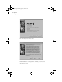
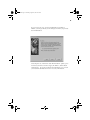
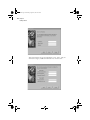
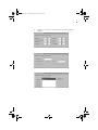
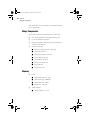
Wbt.book Page 1 Monday, August 2, 1999 4:07 PM
Acer WT 300
User’s Guide
Wbt.book Page 2 Monday, August 2, 1999 4:07 PM
Copyright 1999 Acer Incorporated
All Rights Reserved. Printed in Taiwan
Acer WT 300 User’s Guide
Part No.: 49.32B01.001
Draft Version: July, 1999
Changes may be made periodically to the information in this publication without obligation
to notify any person of such revision or changes. Such changes will be incorporated in new
editions of this manual or supplementary documents and publications. This company makes
no representations or warranties, either expressed or implied, with respect to the contents
hereof and specifically disclaims the implied warranties of merchantability or fitness for a
particular purpose.
Record the model number, serial number, purchase date, and place of purchase information
in the space provided below. The serial number and model number are recorded on the label
affixed to your computer. All correspondense concerning your unit should include the serial
number, model number, and purchase information.
No part of this publication may be reproduced, stored in a retrieval system, or transmitted,
in any form or by any means, electronic, mechanical, photocopy, recording, or otherwise,
without the prior written permission of Acer Incorporated.
Acer WT 300 User’s Guide
Model Number
:_________________________________
Serial Number
:_________________________________
Purchase Date
: _________________________________
Place of Purchase : _________________________________
All trademarks, registered trademarks and/or service marks are the properties
of their respective owners.
Wbt.book Page iii Monday, August 2, 1999 4:07 PM
iii
Notices
FCC Notice
This device has been tested and found to comply with the limits for a Class B
digital device pursuant to Part 15 of the FCC Rules. These limits are designed
to provide reasonable protection against harmful interference in a residential
installation. This device generates, uses, and can radiate radio frequency energy
and, if not installed and used in accordance with the instructions, may cause
harmful interference to radio communications.
However, there is no guarantee that interference will not occur in a particular
installation. If this device does cause harmful interference to radio or television
reception, which can be determined by turning the device off and on, the user is
encouraged to try to correct the interference by one or more of the following
measures:
❑
Reorient or relocate the receiving antenna
❑
Increase the separation between the device and receiver
❑
Connect the device into an outlet on a circuit different from that to
which the receiver is connected
❑
Consult the dealer or an experienced radio/television technician for help
Notice: Shield Cables
All connections to other computing devices must be made using shielded cables
to maintain compliance with FCC regulations.
Notice: Peripheral Devices
Only peripherals (input/output devices, terminals, printers, etc.) certified to
comply with the Class B limits may be attached to this equipment. Operation
with non certified peripherals is likely to result in interference to radio and TV
reception.
Caution
Changes or modifications not expressly approved by the manufacturer could
void the user’s authority, which is granted by the Federal Communications
Commission, to operate this computer.
Wbt.book Page iv Monday, August 2, 1999 4:07 PM
iv
Notices
Use Conditions
This part complies with Part 15 of the FCC Rules. Operation is subject to
the following two conditions: (1) this device may not cause harmful
interference, and (2) this device must accept any interference received,
including interference that may cause undesired operation.
Notice: Canadian Users
This Class B digital apparatus meets all requirements of the Canadian
Interference-Causing Equipment Regulations.
Remarque à l’intention des utilisateurs canadiens
Cet appareil numérique de la classe B respected toutes les exigences du
Règlement sur le matériel brouilleur du Canada.
Important Safety Instructions
Read these instructions carefully. Save these instructions for future
reference.
1.
Follow all warnings and instructions marked on the product.
2.
Unplug this product from the wall outlet before cleaning. Do not
use liquid cleaners or aerosol cleaners. Use a damp cloth for
cleaning.
3.
Do not use this product near water.
4.
Do not place this product on an unstable cart, stand, or table. The
product may fall, causing serious damage to the product.
5.
Slots and openings in the cabinet and the back or bottom are
provided for ventilation; to ensure reliable operation of the product
and to protect it from overheating, these openings must not be
blocked or covered. The openings should never be blocked by
placing the product on a bed, sofa, rug, or other similar surface.
This product should never be placed near or over a radiator or heat
register, or in a built-in installation unless proper ventilation is
provided.
6.
This product should be operated from the type of power indicated
on the marking label. If you are not sure of the type of power
available, consult your dealer or local power company.
7.
Do not allow anything to rest on the power cord. Do not locate
this product where persons will walk on the cord.
8.
If an extension cord is used with this product, make sure that the
total ampere rating of the equipment plugged into the extension
Wbt.book Page v Monday, August 2, 1999 4:07 PM
v
cord does not exceed the extension cord ampere rating. Also, make
sure that the total rating of all products plugged into the wall outlet
does not exceed the fuse rating.
9.
Never push objects of any kind into this product through cabinet
slots as they may touch dangerous voltage points or short out parts
that could result in a fire or electric shock. Never spill liquid of any
kind on the product.
10.
Do not attempt to service this product yourself, as opening or
removing covers may expose you to dangerous voltage points or
other risks. Refer all servicing to qualified service personnel.
11.
Unplug this product from the wall outlet and refer servicing to
qualified service personnel under the following conditions:
12.
a.
When the power cord or plug is damaged or frayed
b.
If liquid has been spilled into the product
c.
If the product has been exposed to rain or water
d.
If the product does not operate normally when the operating
instructions are followed. Adjust only those controls that are
covered by the operating instructions since improper
adjustment of other controls may result in damage and will
often require extensive work by a qualified technician to
restore the product to normal condition.
e.
If the product has been dropped or the cabinet has been
damaged
f.
If the product exhibits a distinct change in performance,
indicating a need for service.
Use only the proper type of power supply cord set (provided in
your accessories box) for this unit. It should be a detachable type:
UL listed/CSA certified, type SPT-2, rated 10A 250V minimum,
VDE approved or its equivalent. Maximum length is 15 feet (4.6
meters).
Wbt.book Page vi Monday, August 2, 1999 4:07 PM
vi
Notices
Year 2000 Compliance Statement
This product is Year 2000-compliant and carries the “NSTL Hardware
Tested Year 2000 Compliant” logo. This product has been tested both by
Acer’s internal test labs and NSTL using NSTL’s YMARK2000
certification test. These tests certify that this product will successfully
make the year 2000 transition.
For more details, check the Acer Year 2000 Resource Center at http://
www.acer.com.tw/service/y2k/
Wbt.book Page vii Monday, August 2, 1999 4:07 PM
vii
Table of Contents
Chapter 1 Getting Started . . . . . . . . . . . . . . . . . . . . . . . . . . . . . . 1
Introduction . . . . . . . . . . . . . . . . . . . . . . . . . . . . . . . . . . . . . . . . . . . . . . . . 2
Overview . . . . . . . . . . . . . . . . . . . . . . . . . . . . . . . . . . . . . . . . . . . . . . . 2
Preinstallation . . . . . . . . . . . . . . . . . . . . . . . . . . . . . . . . . . . . . . . . . . . . . . 3
Selecting a Site . . . . . . . . . . . . . . . . . . . . . . . . . . . . . . . . . . . . . . . . . . 3
Unpacking Components. . . . . . . . . . . . . . . . . . . . . . . . . . . . . . . . . . . . 3
Features . . . . . . . . . . . . . . . . . . . . . . . . . . . . . . . . . . . . . . . . . . . . . . . . 4
Front Panel . . . . . . . . . . . . . . . . . . . . . . . . . . . . . . . . . . . . . . . . . . 4
Rear Panel . . . . . . . . . . . . . . . . . . . . . . . . . . . . . . . . . . . . . . . . . . . 5
Connecting System Components. . . . . . . . . . . . . . . . . . . . . . . . . . . . . 7
Connecting the Keyboard . . . . . . . . . . . . . . . . . . . . . . . . . . . . . . . 7
Connecting the Monitor . . . . . . . . . . . . . . . . . . . . . . . . . . . . . . . . . 8
Connecting the Mouse. . . . . . . . . . . . . . . . . . . . . . . . . . . . . . . . . . 8
Connecting the Printer. . . . . . . . . . . . . . . . . . . . . . . . . . . . . . . . . . 9
Connecting to the Network . . . . . . . . . . . . . . . . . . . . . . . . . . . . . 10
Connecting the Power Adapter . . . . . . . . . . . . . . . . . . . . . . . . . . 10
Connecting the Speaker. . . . . . . . . . . . . . . . . . . . . . . . . . . . . . . . 11
Using the Base Holder . . . . . . . . . . . . . . . . . . . . . . . . . . . . . . . . . 12
Turning On Your System . . . . . . . . . . . . . . . . . . . . . . . . . . . . . . . . . . 13
Turning Off Your System . . . . . . . . . . . . . . . . . . . . . . . . . . . . . . . . . . 14
Setup . . . . . . . . . . . . . . . . . . . . . . . . . . . . . . . . . . . . . . . . . . . . . . . . . . . . 15
Setup Wizard . . . . . . . . . . . . . . . . . . . . . . . . . . . . . . . . . . . . . . . . . . 15
Terminal Connection Manager . . . . . . . . . . . . . . . . . . . . . . . . . . . . . . 21
Microsoft Remote Desktop Client . . . . . . . . . . . . . . . . . . . . . . . . 22
Citrix ICA Client . . . . . . . . . . . . . . . . . . . . . . . . . . . . . . . . . . . . . . 25
Ericom Power Term Terminal Emulator (Optional) . . . . . . . . . . . 31
Multiple Sessions. . . . . . . . . . . . . . . . . . . . . . . . . . . . . . . . . . . . . . . . 32
Terminal Properties . . . . . . . . . . . . . . . . . . . . . . . . . . . . . . . . . . . . . . 33
Chapter 2 Hardware Specifications . . . . . . . . . . . . . . . . . . . . . . 39
Major Components . . . . . . . . . . . . . . . . . . . . . . . . . . . . . . . . . . . . . .
Memory . . . . . . . . . . . . . . . . . . . . . . . . . . . . . . . . . . . . . . . . . . . . . . .
VGA Controller . . . . . . . . . . . . . . . . . . . . . . . . . . . . . . . . . . . . . . . . . .
Serial Port . . . . . . . . . . . . . . . . . . . . . . . . . . . . . . . . . . . . . . . . . . . . .
Parallel Port . . . . . . . . . . . . . . . . . . . . . . . . . . . . . . . . . . . . . . . . . . . .
Software Specification . . . . . . . . . . . . . . . . . . . . . . . . . . . . . . . . . . . .
Bootloader . . . . . . . . . . . . . . . . . . . . . . . . . . . . . . . . . . . . . . . . . .
Operating System . . . . . . . . . . . . . . . . . . . . . . . . . . . . . . . . . . . .
40
40
41
41
41
42
42
42
Wbt.book Page viii Monday, August 2, 1999 4:07 PM
viii
Table of Contents
Drivers. . . . . . . . . . . . . . . . . . . . . . . . . . . . . . . . . . . . . . . . . . . . . 42
Application. . . . . . . . . . . . . . . . . . . . . . . . . . . . . . . . . . . . . . . . . . . . . 43
Troubleshooting Your Terminal . . . . . . . . . . . . . . . . . . . . . . . . . . . . . 44
Wbt.book Page 1 Monday, August 2, 1999 4:07 PM
Getting Started
Chapter 1
Wbt.book Page 2 Monday, August 2, 1999 4:07 PM
2
Chapter 1
Getting Started
Introduction
Acer has been on the leading edge of microcomputer systems
development for both corporate and home computing needs for
20 years, as the OEM of choice for many of the world’s leading
computer companies. Acer is committed to meeting the world’s
demand for state-of-the-art computers at the best prices.
Your Window Based Terminal (WBT) configuration provides
flexible feature in a small footprint making it perfect for general
business or commercial use.
Overview
The Acer WT 300 system is a combination of one Cyrix MediaGX
microprocessor, a Cyrix’s Virtual system architecture enabling
XpressGRAPHICS and XpressAUDIO, an Ethernet Controller
(AMD 79C973), one PCI connector for upgrading to TYPE II
PCMCIA daughter card, and one DIMM socket (which supports
up to 256 MB RAM). The Acer WT 300 system is based on Intel®
x86 architecture with audio capability and 100 BaseT support.
The Acer WT 300 system is one of Acer’s Window Based
Terminal numerous product line. It’s advantages are high
performance, low TCO (Total Cost of Ownership), low
administration cost, good security and seamless integration into
networking environment.
Wbt.book Page 3 Monday, August 2, 1999 4:07 PM
3
Preinstallation
The preinstallation process involves the following activities:
· Selecting a site
· Unpacking components
Selecting a Site
Consider the following when selecting a site for your computer:
· Determine the best site for your system. Cable paths
should not run near equipment that might cause
electromagnetic or radio frequency interference such as
radio transmitters, television sets, copy machines, or heating
and air conditioning equipment.
· Route cables away from personnel and equipment traffic.
· Avoid dusty areas and extremes of temperature and
humidity.
Unpacking Components
Unpack the contents of each box carefully. Save all packing
materials in case you need to move or ship the system in the
future.
Check that all items are present and in good condition. Contact
your dealer immediately if anything is missing or damaged.
Wbt.book Page 4 Monday, August 2, 1999 4:07 PM
4
Chapter 1
Getting Started
Features
The basic configuration consists of a system unit, a base holder,
power adapter and it may also come with an optional SmartCard.
Front Panel
The figure below shows the system unit front panel.
#
Description
1
SmartCard slot
2
Power indicator
3
Manufacturer’s logo
Wbt.book Page 5 Monday, August 2, 1999 4:07 PM
5
Rear Panel
The figure shows the system unit rear panel.
#
Description
1
Parallel/Printer connector
2
Mouse connector
3
Ethernet connector
4
Main power switch
5
Power adapter jack
Wbt.book Page 6 Monday, August 2, 1999 4:07 PM
6
Chapter 1
Getting Started
#
Description
6
USB ports
7
Keyboard connector
8
Serial connector
9
Monitor/VGA connector
10
Line-out/Speaker port
Note : As of now, Windows CE does not support the USB port, it will be
available in the future.
Wbt.book Page 7 Monday, August 2, 1999 4:07 PM
7
Connecting System Components
Do not turn on the power until you finish connecting the system
components.
The following sections show how to connect each component to
the system.
Connecting the Keyboard
Plug the keyboard cable into the keyboard connector on the rear
panel. See the figure below.
Wbt.book Page 8 Monday, August 2, 1999 4:07 PM
8
Chapter 1
Getting Started
Connecting the Monitor
Plug the monitor signal cable into the VGA connector on the rear
panel.
Connecting the Mouse
Plug the mouse cable into the mouse connector on the rear
panel.
Wbt.book Page 9 Monday, August 2, 1999 4:07 PM
9
Connecting the Printer
If you have a parallel printer, connect it to the parallel connector
on the rear panel. See figure below.
Wbt.book Page 10 Monday, August 2, 1999 4:07 PM
10
Chapter 1
Getting Started
Connecting to the Network
Plug into the network via the Ethernet connector to the hub. See
figure below.
Connecting the Power Adapter
Plug one end of the power adapter to the power adapter jack,
and then one end to the power cord, then plug the other end of
the power cord into the wall outlet.
Wbt.book Page 11 Monday, August 2, 1999 4:07 PM
11
Connecting the Speaker
The figure below shows the connection of the speaker to the
system.
Wbt.book Page 12 Monday, August 2, 1999 4:07 PM
12
Chapter 1
Getting Started
Using the Base Holder
Your system also includes a base holder to save precious table
space. See figure below for the assembly.
Wbt.book Page 13 Monday, August 2, 1999 4:07 PM
13
Turning On Your System
After you have connected all peripherals and cables, follow these
steps to turn on your computer:
1.
Turn on all peripherals connected to the system such as
monitor, printer, etc.
2.
Turn on the main power switch located at the back of the
system.
Note: If your system needs a SmartCard to power on, then insert the
SmartCard into the slot in front of the system. See your SmartCard manual for
more detail.
Caution: The SmartCard should be inserted correctly, the circuit chip should
be facing down and in front as shown below, for the system to power up
properly. See your SmartCard manual for more detail.
3.
After inserting the SmartCard, the system will boot up and
the Acer logon screen will be displayed.
Wbt.book Page 14 Monday, August 2, 1999 4:07 PM
14
Chapter 1
Getting Started
Turning Off Your System
1.
Log off from the server and then turn off the power of the
system.
2.
Turn off all peripherals connected to the system such as
the monitor, printer, etc.
3.
Turn off the main power switch and unplug the system if
you are going to do any of the following
■
not use the system for a long period of time
■
install system component(s)
Note: If your system is equipped with a SmartCard, remove the SmartCard first
before turning off the system.
Warning! Installing components without unplugging the system may result in
serious damage both to the system and the component. Unplugging the
system ensures that there is no standby current on the system board. Not
doing so may damage your system.
Wbt.book Page 15 Monday, August 2, 1999 4:07 PM
15
Setup
The setup refers to the Setup Wizard and the Terminal Properties.
The Setup Wizard is used when the Acer WT 300 is installed for
the first time. The Terminal Properties is used after the Setup
Wizard is set.
Setup Wizard
The Setup Wizard lets you set terminal network configuration
and terminal display parameters. Any future changes can be
made using the Terminal Properties dialog box. You can launch
this dialog box anywhere in the program at any time by pressing
the [F2] key, see Terminal Properties on page 33.
There are several dialog boxes that display in succession during
the process. Each dialog box is self-explanatory. Some dialog
boxes are informational and require no user input. Other dialog
boxes will prompt you for network and display information.
Click on the “Next” or “Accept” buttons to display the next dialog
box in the sequence. Click on the Back command button to
return to the previous dialog box. Click on Cancel to quit and
display the Terminal Connections Manager. Following are the
dialog boxes of the Setup Wizard.
Wbt.book Page 16 Monday, August 2, 1999 4:07 PM
16
Chapter 1
Getting Started
Press next to go to the next screen.
Read the end user’s license agreement carefully, press “Accept” to
go to the next screen.
Wbt.book Page 17 Monday, August 2, 1999 4:07 PM
17
If you choose the “Yes, use the IP information supplied by
DHCP” you will go directly to the dialog box where you provide
the IP information.
Choosing the “No, I will enter status IP information” option, press
next and you will be asked to supply IP address, Subnet Mask
and Gateway. If you do not know the information, you can ask
your network administrator for the necessary information.
Wbt.book Page 18 Monday, August 2, 1999 4:07 PM
18
Chapter 1
Getting Started
After supplying the necessary information, press “Next”, and you
will have to supply additional information as shown below.
Wbt.book Page 19 Monday, August 2, 1999 4:07 PM
19
When the necessary information is supplied, choose “Next” to set
your video display resolution. The screen below shows the
current setting of the video display resolution.
Note: Make sure the resolution you select is supported by you monitor,
otherwise your monitor will only display a blankscreen.
After choosing your video display resolution, choose next and
click on “Finish” to finish the setup. A dialog box will be
displayed asking you if you want to keep the selection. Choose
“OK” to keep the selection or “Cancel” to pick another one.
Wbt.book Page 20 Monday, August 2, 1999 4:07 PM
20
Chapter 1
Getting Started
If you choose “OK” the following screen will be displayed saying
that you have successfully completed the Setup Wizard. Click
“Finish” to apply the settings that you have chosen.
After clicking the “Finish”, you will be asked to restart the system
in order for the settings to take effect. Click on “Yes” to restart
the system, otherwise, click “No”.
Wbt.book Page 21 Monday, August 2, 1999 4:07 PM
21
Terminal Connection Manager
Terminal Connection Manager dialog box is designed to help you
manage your terminal's network connections. The dialog box
displays after you are finish with the Setup Wizard. This is the
screen that is displayed everytime you start your terminal and
want to log onto a server. It can support up to seven different
server connections. This section guide you through the steps on
some of the features of the Terminal Connection Manager.
1.
The Connection and the Configure are the two main
options in the Terminal Connection Manager.
2.
In order to connect to a server for the very first time, you
should go the the “Configure” option. Click on the
“Configure” option and click on “Add”.
Wbt.book Page 22 Monday, August 2, 1999 4:07 PM
22
Chapter 1
Getting Started
3.
On the “New Connection” dialog box, you can choose a
“Citrix ICA Client”, “Ericom Power Term Terminal Emulator”
or “Microsoft Remote Desktop Client” type of connection to
create.
Note: “Citrix ICA Client” and “Microsoft Remote Desktop Client” is a Windows
NT based type of operating system, while “Ericom Power Term Terminal
Emulator” is a Unix system.
Microsoft Remote Desktop Client
To create a new “Microsoft Remote Desktop Client”, use the WTS
Connection Wizard. Make selections and enter data in each
dialog box. Click on the Next command button to move to the
next dialog box. When you are finished, the new connection will
Wbt.book Page 23 Monday, August 2, 1999 4:07 PM
23
be added to the Connection Name list in the Terminal
Connection Manager.
Use the Back command button to go to the previous dialog box.
Click on the Cancel command button to quit this dialog box at
any time.
The following figures show the sequence of the WTS Connection
Wizard.
Wbt.book Page 24 Monday, August 2, 1999 4:07 PM
24
Chapter 1
Getting Started
After you are finished with the configuration, you can get
connected to a server by going to the connection option and
double-clicking on a connection name or you can also highlight a
connection name and click on “Connect”.
Wbt.book Page 25 Monday, August 2, 1999 4:07 PM
25
Citrix ICA Client
The following procedure describes how to create a network
connection to a Citrix server.
Creating a Network Connection
1.
In the Connection Manager dialog box click the Configure
tab and then click “Add”.
2.
In the New Connection dialog box, click Citrix ICA Client in
the type of connection list. Click “OK”.
3.
In the Specify Connection Type dialog box, click “Network
Connection”. Make sure your client device is connected to
the network through a NIC or by a serial PPP connection to
a Windows 95 or Windows NT RAS server. Click "Next" to
continue.
Wbt.book Page 26 Monday, August 2, 1999 4:07 PM
26
Chapter 1
Getting Started
4.
The Select a Citrix Server or Published Application screen
will appear and If your Windows CE device is not on the
same network as the Citrix server you want to connect to
(for example, if you are on the other side of a router, across
the Internet, or using RAS to connect to a remote network
containing Citrix servers), the server and published
application list will not contain that server. In this case, click
“Server Location” and go to Step 5. Otherwise, scroll
through the list and select the Citrix server or published
application or type the name of the Citrix server or
published application in the edit field. Click “Next” to
continue, and go to Step 6.
5.
In the Server Location screen, the ICA Windows CE Client
uses the information entered in the Server Location dialog
to help locate available Citrix servers and published
applications. The default value entered in the Address field
is Auto-Locate. To use Auto-Locate, your Windows CE
device and the Citrix server you want to connect to must be
on the same local network. If you are on another network
(for example, if you are on the other side of a router, across
the Internet, or connected by RAS) you must enter the IP
address or DNS name of a Citrix server on the network that
contains the Citrix server you want to connect to. Click
“Add” and enter the IP address or DNS name of any Citrix
Wbt.book Page 27 Monday, August 2, 1999 4:07 PM
27
server on the remote network. Click “OK”. The Select a
Citrix Server or Published Application screen reappears.
Scroll through the list and select the name of the Citrix
server or published application you want to connect to.
Click “Next” to continue.
6.
The Specify an Application screen will appears and in the
Command Line field, enter the path and name of an
application to run on the server once the logon to the Citrix
server is successful. Leave this field blank to run a Windows
NT desktop on the Citrix server. Working Directory lets you
associate a directory with the application specified in the
Command Line field. Enter the drive and path of the
working directory in the Working Directory field. For
example, if the application Notepad.exe is in the C:\WTSRV
directory on the Citrix server, type C:\WTSRV\Notepad.exe
in the Command Line field. If you use Notepad to work on
documents in the C:\My Documents directory, type C:\My
Documents in the Working Directory field. When you log
on to the Citrix server, Notepad begins. In Notepad, if you
click the File menu, the directory C:\My Documents is
displayed. Click “Next” to continue.
7.
In the Specify Logon Information screen, typea valid
username, domain, and password. If you leave these fields
blank, you are prompted for your username, domain, and
Wbt.book Page 28 Monday, August 2, 1999 4:07 PM
28
Chapter 1
Getting Started
password when the ICA Windows CE Client connects to the
Citrix server. Click “Next” to continue.
8.
In the Select Window Option screen, select 16 or 256 colors
from the Window Colors field. Click “Next” to continue.
9.
In the Compression, Cache, and Sound screen, click
Compress Data Stream to reduce the amount of data
transferred between the ICA Windows CE Client and the
Citrix server hosting the session. (If your connection is
bandwidth-limited, enabling compression may increase
performance. If your client device is on a high-speed LAN,
you may not need compression.) The Cache feature is not
supported in this release. Click “Enable Sound” to enable
sound support. Remote applications will be able to play
sounds on your client. From the pull-down list, select a
sound presentation quality level. High provides the
greatest audio quality but should only be used when
bandwidth consumption is not a concern. Medium results
in less bandwidth consumption than when using High.
Compression of sound data provides greater bandwidth
efficiency but reduces sound quality somewhat. This value
is recommended for most LAN-based connections. Low
offers the most efficient use of bandwidth but also
decreases sound quality severely. This value is
Wbt.book Page 29 Monday, August 2, 1999 4:07 PM
29
recommended for low-bandwidth connections, including
most modem connections. Click “Next” to continue.
10.
By default, the Citrix server or published application name
appears in the edit field. You can accept this name or enter
another. The name you choose will be the name of the
entry in the Current Client Connections list and will appear
in the title bar of the ICA session window. Click Finish.
Click OK to the confirmation message.
Creating a Dial-In Connection
1.
In the Connection Manager dialog box click the Configure
tab and then click “Add”.
2.
In the New Connection dialog box, click Citrix ICA Client in
the type of connection list. Click “OK”.
3.
In the Specify Connection Type dialog box, click “Dial-In
Connection”. Make sure your client device is connected to
the network through a NIC or by a serial PPP connection to
Wbt.book Page 30 Monday, August 2, 1999 4:07 PM
30
Chapter 1
Getting Started
a Windows 95 or Windows NT RAS server. Click "Next" to
continue.
4.
From the pull-down list in the Dial-In Devices screen, select
your modem. In the Area, Phone Number, and Country
fields, type the area code, phone number, and country code
of the Citrix server. Click Next to continue.
5.
From here on follow the Step 6 of the “Network
Connection” on page 27.
Connecting to a Citrix Server.
1.
In the Connection Manager dialog box.
2.
Click the Connections tab.
3.
Select the desired connection description and click
Connect. If the remote application entry contains a valid
user name and password, the ICA Client logs in as that user
name. If no user name and password are present in the
entry, the server logon dialog box appears. Enter a valid
user name and password for the Citrix server and click OK
to begin the session.
Wbt.book Page 31 Monday, August 2, 1999 4:07 PM
31
Ericom Power Term Terminal Emulator (Optional)
1.
Select “Ericom Power Term Terminal Emulator” and click
on “OK” to go to the next dialog box.
2.
On this dialog box, you will be asked to supply some
information in order to connect to the server. Click on “OK”
to add that to the Terminal Connection Manager’s
Connection Name.
Wbt.book Page 32 Monday, August 2, 1999 4:07 PM
32
Chapter 1
Getting Started
Multiple Sessions
To start a multiple sessions:
1.
2.
From one of the active session:
a.
Press “Ctrl+Alt+End” (“End” key on the editing keypad)
to call up the Terminal Connection Manager.
b.
Click on another connection to connect and start
another session.
From the Terminal Connection Manager:
a.
Click on another connection to connect and start
another session.
To toggle between sessions:
❑
Press “Ctrl+Alt+ ▼ “ ( arrow down) to proceed to the next
session.
❑
Press “Ctrl+Alt+ ▲ “ ( arrow up) to proceed to the previous
session.
Wbt.book Page 33 Monday, August 2, 1999 4:07 PM
33
Terminal Properties
Terminal Properties is used to change the setting of the terminal.
This sections guide you through the steps on some of the
features of Terminal Properties.
1.
Everytime you press the F2 function key, the following
screen will be displayed:
a.
2.
You can either click on okay to start your system or
you can pick one of the options on top of the dialog
box.
Click on the “Input” option to choose the input devices for
your system. The following screen shows the information
of the input devices that you can set.
Wbt.book Page 34 Monday, August 2, 1999 4:07 PM
34
Chapter 1
Getting Started
3.
You can also choose the display option to set the video
display resolution and to enable the screen saver.
Note: Make sure the resolution you select is supported by you monitor,
otherwise your monitor will only display a blankscreen.
Wbt.book Page 35 Monday, August 2, 1999 4:07 PM
35
4.
Click on the “Network” option to specify another network
settings. You can choose to “Obtain an IP address from a
DHCP server” or “Specify an IP address”. The following
screen shows the informations that needs to be supplied by
the users.
5.
Choosing the “Specify an IP address” will require you to
supply the IP address, Subnet Mask and Gateway. And you
can go to the Advanced option to supply additional
information. The following screen shows the Advanced
option dialog box.
Wbt.book Page 36 Monday, August 2, 1999 4:07 PM
36
Chapter 1
Getting Started
6.
Choosing the “Misc” will enables you to put identification
on your computer, enable remote upgrade function, control
the sound volume and set the global ICA Client Setting.
Wbt.book Page 37 Monday, August 2, 1999 4:07 PM
37
7.
Below are the three screen shots of the Global ICA Client
Settings.
Wbt.book Page 38 Monday, August 2, 1999 4:07 PM
38
Chapter 1
Getting Started
Wbt.book Page 39 Monday, August 2, 1999 4:07 PM
Hardware
Specifications
Chapter 2
Wbt.book Page 40 Monday, August 2, 1999 4:07 PM
40
Chapter 2
Hardware Specifications
This chapter describes the hardware specification and all its
major components.
Major Components
The system board has the following major components:
❑
CPU: Cyrix MediaGX LV 200 MHz internal speed
❑
Up to 256 MB Ram supported
❑
Ethernet Controller: AMD AM79C973 which supports
100BaseT and 10BaseT
❑
External connectors
■
PS/2 keyboard and mouse connectors
■
One serial connector
■
One parallel/printer connector
■
One standard VGA port
■
One Ethernet connector
■
One power adapter jack
■
Two USB ports
■
One speaker port
Memory
❑
❑
Flash
■
Boot Loader data bus : 8-bit
■
Boot Loader type : EEPROM
■
Boot Loader size: 256KB
■
Storage size : 8M DOC
System Memory
■
Memory data bus : 64-bit
Wbt.book Page 41 Monday, August 2, 1999 4:07 PM
41
■
DIMM type : 100 MHz SDRAM
■
Max DIMM module size : 256 MB
VGA Controller
❑
Built in MediaGX with Virtual system architecture
❑
VGA memory size is shared with system memory
Resolution
Colors
Frequency
640 x 480
256
60
800 x 600
256
60
1024 x 768
256
60
Serial Port
❑
One high speed Ns 16c550 compatible UART built-in NS
super I/O PC97317
❑
Onboard 9-pin D type connector
Parallel Port
❑
Standard Mode/ECP/EPP mode
■
IBM PC/AT and PS/2 compatible bidirectional parallel
port
■
Onboard 25-pin D type connector
Wbt.book Page 42 Monday, August 2, 1999 4:07 PM
42
Chapter 2
Hardware Specifications
Software Specification
Bootloader
❑
Boot ROM - contains basic system initialization code and
OS loader for Disk On Chip
❑
OS and application image stored in Disk On Chip
Operating System
❑
Client side: Microsoft Windows CE 2.11
■
Microsoft RDP Client
■
Citrix ICA Client
■
Ericom Power Term Terminal Emulator
❑
Server side: Microsoft Windows NT Server (Terminal Server
Edition)
❑
Citrix Metra Frame Server
❑
SVGA driver MediaGX (2D acceleration enabled)
Drivers
■
640 x 480 x 256 at 60, 72, 75 Hz
■
800 x 600 x 256 at 60, 72, 75 Hz
■
1024 x 768 x 256 at 60, 72, 75 Hz
■
1280 x 1024 x 256 at 60, 72, 75 Hz
❑
PS/2 keyboard and mouse driver
❑
LAN driver for AMD AM79C972
❑
Permanent storage driver for Disk On Chip 2000
❑
SmartCard driver
■
ISO 7816-3 (T=1) Compliant
■
ISO 7816-4 Compliant
Wbt.book Page 43 Monday, August 2, 1999 4:07 PM
43
❑
Serial and parallel port driver
Application
❑
Acer customized logon screen
❑
Terminal configuration setup program
❑
Windows Terminal Client
Wbt.book Page 44 Monday, August 2, 1999 4:07 PM
44
Chapter 2
Hardware Specifications
Troubleshooting Your Terminal
The following table lists some possible situations that may arise
during the use of your terminal and provides easy answers and
solutions. If you still encounter problems which you cannot
resolve, please call any authorized dealer or distributor for
assistance.
Problem
Solution
When the terminal is turned on,
nothing happens.
Check the power cord. It should be
plugged into an AC outlet and should
be properly connected to the AC
power connector on the terminal’s
back panel.
If the terminal needs a SmartCard to
power-on, make sure that the
SmartCard is inserted properly. See
“Turning On Your System” on page 13
for more detail.
When the terminal is turned on,
the Terminal Connection Manager
or the Setup Wizard appears, but
the mouse is not working.
Make sure that the mouse is plugged
properly into the PS/2 mouse port on
the terminal’s back panel. See
“Connecting the Mouse” on page 8 for
more detail.
During the terminal’s Power-On
Self-Test (POST), a message is
displayed: “Keyboard not
detected”.
Make sure that the keyboard is
properly connected to the terminal’s
PS/2 keyboard port on the terminal’s
back panel. See “Connecting the
Keyboard” on page 7 for more detail.
Wbt.book Page 45 Monday, August 2, 1999 4:07 PM
45
Problem
Solution
The parallel printer connected to
my terminal does not respond
when I try to print to it.
1. Make sure that the printer is
plugged into the proper outlet and
is turned on.
2. Check the cable connection from
the printer to the terminal. See
“Connecting the Printer” on page 9
for more detail.
3. Make sure that the printer is online.
4. Make sure that the printer is
properly configured in the
application server’s Print Manager,
and that the printer has not been
paused.
You are not able to make a network
connection using the Terminal
Connection Manager.
1. Press the “F2” key to call up the
Terminal Properties dialog box.
Select the Network tab and verify
that the proper method for
specifying the IP address is
selected, DHCP or static IP. If a
static IP address is selected, verify
that the IP, the subnet mask, and
the gateway IP address are correct
for the subnet that the terminal is
connected to.
2. Make sure that the cable is
connected to the network
connector on the back panel of the
terminal. Check to make sure that
the other end of the cable is
connected to a hub or other
network outlet.
3. If DHCP addressing is selected,
check with your network
administrator to make sure that
the DHCP server for your subnet is
functioning properly.
Wbt.book Page 46 Monday, August 2, 1999 4:07 PM
46
Chapter 2
Hardware Specifications
Problem
Solution
When a user improperly
disconnects from the server, the
user is not able to log on to the
server again and the sound device
does not work properly.
If a user improperly disconnects from
the server (i.e., suddenly turns off the
power of the terminal without logging
off), there will be an un-log off
session in the terminal server, which
causes the terminal to be unable to
log on to the server again, and since it
occupies some system resources like
the sound device, the sound device
will probably not work. When this
problem occurs, please ask the
administrator to clear the idle session
from the server so that you can log on
again.