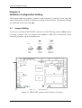
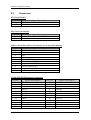
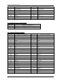
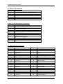
1
PEB-6530VL Embedded System Board User's Manual P/N: B8980920 Version 1.0 Copyright © Portwell, Inc., 2002. All rights reserved. All other brand names are registered trademarks of their respective owners. Preface Table of Contents How to Use This Manual Chapter 1 Introduction........................................................................................................1-1 1.1 1.2 Check List .............................................................................................................................1-1 Product Specifications.........................................................................................................1-2 1.2.1 Mechanical and Environmental...........................................................................1-3 1.2.2 Mechanical Drawing .............................................................................................1-4 1.3 System Architecture ............................................................................................................1-4 1.3.1 CPU/GX1 and CS5530A.......................................................................................1-4 1.3.2 XPRESS Graphics...................................................................................................1-5 1.3.3 PCI Bus....................................................................................................................1-5 1.3.4 SDRAM Interface...................................................................................................1-5 1.3.5 IDE Interface ..........................................................................................................1-5 1.3.6 USB ..........................................................................................................................1-5 1.3.7 Ethernet...................................................................................................................1-6 1.3.8 Winbond W83977F-A & W83977ATF-AW ........................................................1-6 1.3.9 Compact Flash Interface .......................................................................................1-6 Chapter 2 2.1 2.2 Jumper Setting......................................................................................................................2-1 Connectors ............................................................................................................................2-3 Chapter 3 3.1 3.2 3.3 3.4 3.5 3.6 3.7 System Installation............................................................................................3-1 Graphic Driver installation for NS Geode GX1 XpressGRAPHICS ..............................3-1 IDE interface.........................................................................................................................3-2 PCI bus ..................................................................................................................................3-2 SDRAM interface .................................................................................................................3-2 USB ........................................................................................................................................3-2 Compact Flash interface......................................................................................................3-2 Winbond W83977F-A & W83977ATF-AW.......................................................................3-3 Chapter 4 4.1 4.2 Hardware Configuration Setting ......................................................................2-1 BIOS Setup Information ....................................................................................4-1 Starting Setup .......................................................................................................................4-1 Main Menu ...........................................................................................................................4-2 4.2.1 STANDARD CMOS SETUP.................................................................................4-7 4.2.2 BIOS FEATURES SETUP....................................................................................4-10 4.2.3 PASSWORD SETTING .......................................................................................4-14 4.2.4 CHIPSET FEATURES SETUP ............................................................................4-15 4.2.5 INTEGRATED PERIPHERALS FEATURES SETUP.......................................4-17 4.2.6 POWER MANAGEMENT SETUP ....................................................................4-19 4.2.7 PNP/PCI CONFIGURATION SETUP..............................................................4-21 Preface How to Use This Manual The manual describes how to configure your PEB-6530VL system to meet various operating requirements. It is divided into four chapters, with each chapter addressing a basic concept and operation of Embedded Board Computer. Chapter 1: Introduction. This chapter presents what you have in the inside of box and give you an overview of the product specifications and basic system architecture for this model of single board computer. Chapter 2: Hardware Configuration Setting. This chapter shows the definitions and locations of Jumpers and Connectors that you can easily configure your system. Chapter 3: System Installation. This chapter describes how to properly mount the CPU and main memory, Solid State Flash disk, or optional flat panel display interface module to get a safe installation and give you a programming guide of Watch Dog Timer function. Besides, it will introduce and show you the driver installation procedure about Graphics Controller. Chapter 4: BIOS Setup Information. This chapter specifies the meaning of each setup parameters and how to get advanced BIOS performance and update new BIOS. In addition, POST checkpoint list will give you a guide of trouble-shooting. The content of this manual and EC declaration document is subject to change without prior notice. These changes will be incorporated in new editions of the document. Portwell may make supplement or change in the products described in this document at any time. Updates to this manual, technical clarification, and answers to frequently asked questions will be shown on the following web site: http://www.portwell.com.tw Preface EC Declaration of Conformity (To Be Added) For the following equipment: Product Name: Model Name: Trade Name: is herewith confirmed to comply with the requirements set out in the Council Directive on the Approximation of the Laws of the Member States relating to Electromagnetic Compatibility Directive (89/336/EEC). The equipment was evaluated and passed the test, the following standards were applied : EMC : EN 55022 EN 50082-2 EN 61000-4-2 EN 61000-4-3 EN 61000-4-4 EN 61000-3-2 EN 61000-3-3 (1994/A1:1995 Class A) (1991) (1995) (1996) (1995) (1995) (1995) The following manufacturer is responsible for this declaration : Portwell, Inc. (Company Name) 3F, No.88, Sec.1, Nei-Hu Rd., Taipei, Taiwan, R.O.C. (Company Address) Taipei, R.O.C. Place Date Legal Signature of Authorized Person Introduction Chapter 1 Introduction This manual describes in detail the Portwell PEB-6530VL Embedded System Board. This manual aims to provide all necessary information to users who may interest in using all PEB-6530VL’s functions. The PEB-6530VL is a low power ISA Bus half-sized SBC that equips with low-power NS Geode GX1 processor, VGA, and single PCI-bus Ethernet interfaces. This model is very compact with extensibility. For an embedded system, Watch Dog Timer is also one standard feature. It helps to free the system from undesired hanging without human interface. This is unique for many Embedded System applications. Other impressive features include the a Compact Flash socket for Compact Flash storage card, four serial ports, one parallel port, and two 144-pin SODIMM sockets allowing for up to 384MB of SDRAM to be installed. 1.1 Check List The PEB-6530VL package includes the following basic items accompany with this manual. 1 PEB-6530VL All-in-One NS Geode GX1 Computing Module 1 CD-ROM contains the followings: - User’s Manual (this manual in PDF file) - Ethernet driver and utilities - VGA drivers and utilities - Latest BIOS (as of the CD-ROM was made) Cable set includes the followings: - 1 Bracket with one PS/2 K/B mouse port cable - 1 PS/2 Keyboard and mouse Y cable (10-pin, Mini-DIN) - 1 IDE HDD cable (40-pin, pitch 2.54mm) - 1 FDD cable (34-pin, pitch 2.54mm) - 1 bracket with one Printer port cable (26-pin, pitch 2.0mm) - 2 bracket with two serial port cable ( 10-pin, pitch 2.54mm) - 4 pin to 4 pin ATX control cable If any of these items is damaged or missed, please contact your vendor and save all packing materials for future replacement and maintenance. PEB-6530VL User’s Manual 1-1 Introduction 1.2 Product Specifications Main processor Onboard NS Geode GX1 300MHz, BGA package BIOS Award 256KB Flash BIOS Chipset NS Geode CS5530A I/O Chipset Winbond W83977F-A, Winbond W83977ATF-AW Memory On board two 144-pin SODIMM socket supports up to 512 Mbytes SDRAM Enhanced IDE Supports two IDE devices. Supports Ultra DMA/33 mode with data transfer rate up to 33MB/sec. FDD interface Supports up to one floppy disk drives, 5.25" (360KB and 1.2MB) and/or 3.5" (720KB, 1.44MB, and 2.88MB) Parallel port Interface for bi-directional parallel port x 1. Supports SPP, ECP, and EPP modes Serial port Two internal header supports RS-232 x 2, two internal header supports RS-422/485 x 2. Ports can be configured as COM1, COM2, COM3, COM4, or disabled individually. (16C550 equivalent) KB/Mouse connector Internal header PS2 Keyboard/Mouse connector x 1 USB connectors One 5 x 2 header on board supports dual USB ports or external down link 2 connector. Watchdog Timer Super watchdog timer from 0.5 to 64 sec by hardware count & software trigger. DMA 7 DMA channels (8237 equivalent) Interrupt 15 interrupt levels (8259 equivalent) Power management I/O peripheral devices support power saving and doze/standby/suspend modes. APM 1.2 compliant. PEB-6530VL User’s Manual 1-2 Introduction Display Chipset NS Geode CS5530A Display memory Shared display memory up to 4MB Display type Supports non-interlaced CRT. Resolution Up to 1024x768x16 bpp Fast Ethernet Chipset One Intel 82559 PCI-bus Ethernet controllers on board Ethernet interface PCI 100/10 Mbps, IEEE 802.3U compatible Remote Boot-ROM For diskless system SSD interface One CF socket supports Type II Compact Flash Card (Support 8-320MB Compact flash) Expansion interface One PICMG Golden Finger Connectors on the bracket VGA (DB-15), Ethernet (RJ-45), PS/2 Keyboard/Mouse and USB for Specific Power connectors From PICMG Golden Finger 1.2.1 Mechanical and Environmental Power supply voltage: +12V (11.4V to 12.6V) Typical power requirement: 5V @ 1.66A w/ GX1 300MHz Operating temperature: 32 to 122°F (0 to 50°C) Board size: 121.5mm x 185mm PEB-6530VL User’s Manual 1-3 Introduction 1.2.2 Mechanical Drawing 185 91.7 1.9 63.75 6 35.85 41.82 1.3 System Architecture 1.3.1 CPU/GX1 and CS5530A 15.49 19.5 5.05 4.32 16.8 7.62 50.12 33.8 75.67 121.9 178 98.5 3.5 5.05 The NS Geode GX1 along with the CS5530A companion chip provide the basic functionality and buses of the system: Interface to SDRAM, 64-bit data bus. PC100 compliant SDRAM must be used. PCI interface provided by GX1 CPU. PCI to ISA Bridge provided by CS5530A. VGA controller with video memory shared with system memory (UMA). The image data is transferred to the companion chip by means of Pixel bus. CRT interface. Data provided by the Pixel and Video interface from the CPU. Video interface from GX1 to the CS5530A. This data-stream is buffered and multiplexed with the Pixel bus for windowed video viewing. This interface may assist the processor in connection motion picture decoding. USB integrated in the CS5530A. IDE interface support Ultra DMA. Tow connectors are provided: A 40 pin pitch 2.54mm standard IDE interface on the primary and secondary controller and a Compact Flash connector on the secondary controller. PEB-6530VL User’s Manual 1-4 Introduction 1.3.2 XPRESS Graphics The XPRESS Graphics is based on the GX1 CPU and the CS5530A Companion chip and this graphics controller is very cost efficient since almost no additional components are required. This is achieved by using the SDRAM as frame-buffer and by integrating the graphics engine and display interface in the GX1 CPU and the CS5530A companion chip. This controller provides a CRT interface. 1.3.3 PCI Bus The PCI-bus on the board is provided by the GX1 CPU and will always run at 33MHz. The GX1 CPU provides support for up to three bus masters. These bus master signals are used by the CS5530A and the Intel 82559 Ethernet controller. 1.3.4 SDRAM Interface This board uses SODIMM up to 512MB 3.3V PC 100 SDRAM modules are recommended to use. 1.3.5 IDE Interface A primary as well as a secondary IDE controller is provided by the CS5530A companion chip which supports Ultra DMA mode and PCI bus mastering for the data transfer. Access to these controllers is provided by a standard IDE 40-pin connector and a Compact Flash type II connector on the solder side of this board. 1.3.6 USB The USB interface provides two USB channels that are controlled by the CS5530A. The signals are provided two 5 pin header that can be connected to standard USB bracket adapter or use down link connector. PEB-6530VL User’s Manual 1-5 Introduction 1.3.7 Ethernet The Ethernet interfaces are based on one Intel 82559 Ethernet controller, which support both 100Mbit as well as l0Mbit Base-T interface. The Ethernet controllers are attached to the PCI bus and use PCI bus mastering for data transfer. The CPU is thereby not loaded during the actual data transfer. 1.3.8 Winbond W83977F-A & W83977ATF-AW The Winbond W83977F-A Super I/O chip provides most input / output interfaces of the system as the following: COM 1 & 2. Operates in RS-232 mode through a charge pump driver. Only 5V supply is required COM 3 & 4. A RS422/RS485 driver is used whereby RS-422 and RS-485 are provided. Selection of the mode is made by hardware jumper. Driver uses charge pumps whereby only +5V is required LPT. Support for SPP, EPP and ECP modes Floppy interface Keyboard interface PS/2 Mouse interface Provision of buffered ISA data bus for BIOS (denoted XDBus) NVRAM with battery backup for BIOS configuration and real time clock Watchdog timer 1.3.9 Compact Flash Interface A Compact Flash type II connector is connected to the secondary IDE controller. The Compact Flash storage card is IDE compatible. It is an ideal replacement for standard IDE hard drives. The solid-state design offers no seek errors even under extreme shock and vibration conditions. The Compact Flash storage card is extremely small and highly suitable for rugged environments, thus providing an excellent solution for mobile applications with space limitations. It is fully compatible with all consumer applications designed for data storage PC card, PDA, and Smart Cellular Phones, allowing simple use for the end user. The Compact Flash storage card is O/S independent, thus offering an optimal solution for embedded systems operating in non-standard computing environments. The Compact Flash storage card is IDE compatible and offers various capacities. The following block diagram shows the architecture and main components of PEB-6530VL. PEB-6530VL User’s Manual 1-6 Introduction SDRAM Port SODIMM SDRAM 100/10 BASE RJ-45 Geode GX1 Processor Clocks Intel 82559 Serial Packet YUV Port PCI Interface RGB Ports Compact Flash PCI Bus Ultra IDE RS-232x2 USB (2 Ports) Graphics Data Geode CS5530 I/O Companion LPT Video Data RS-422/ 485x2 Winbond W83977F-A Analog RGB W83977ATF-AW BIOS CRT 14.318 GPIO KBD PS/2 Mouse Watchdog Timer ISA Bus Figure 1-1 PEB-6530VL System Block Diagram The two key components on board are the NS Geode GX1 CPU and the CS5530A companion chip. These two devices provide the ISA and PCI bus to which all the major components are attached. PEB-6530VL User’s Manual 1-7 Hardware Configuration Setting Chapter 2 Hardware Configuration Setting This chapter indicates jumpers’, headers’; and connectors’ locations. Users may find useful information related to hardware settings in this chapter. The default settings are indicated with a start sign (★). 2.1 Jumper Setting For users to customize PEB-6530VL's features. In the following sections, Short means covering a jumper cap over jumper pins; Open or N/C (Not Connected) means removing a jumper cap from jumper pins. Figure 2-1 PEB-6530VL Jumper and Connector Locations PEB-6530VL User’s Manual 2-1 Hardware Configuration Setting RTC CMOS Clear Jumper Setting (JP1) JP1 1-2 2-3 Process Selection Normal Operation Clear CMOS Contents WATCH DOG TIMER Jumper Setting (JP5) JP5 1-2 NC Short JP5 3-4 NC Short JP5 5-6 Short Short Short Short NC NC NC NC Processor Selection Watch DOG Timer Enabled Watch DOG Timer Disabled IO Port Location 533/033 543/343 JP5 7-8 Short Short NC NC Short Short NC NC JP5 9-10 Short NC Short NC Short NC Short NC Twd 0.5 sec 1 sec 2 sec 4 sec 8 sec 16 sec 32 sec 64 sec On-board Ethernet enable/disable (JP3) JP3 1-2 2-3 Processor Selection On-board Ethernet Enabled On-board Ethernet Disabled On-board COM port setting JP7 1-2 2-3 5-6 7-8 Processor Selection RS-422 FOR COM3 RS-485 FOR COM3 RS-422 FOR COM4 RS-485 FOR COM4 PEB-6530VL User’s Manual 2-2 Hardware Configuration Setting 2.2 Connectors JP2: Reset Header PIN No. 1 2 Signal Description Reset Ground JP6: Power On Header PIN No. 1 2 Signal Description Power On Ground J18/J19 : Serial Port-3/Port-4 Connector (2 x 5 shrouded header) PIN No. 1 2 3 4 5 6 7 8 9 10 Signal Description TXTX+ RX+ RXGround (GND) Data Set Ready (DSR) Request to Send (RTS) Clear to Send (CTS) Ring Indicator (RI) N/C J13 /J8: IDE1/IDE2 Interface Connector PIN No. 1 3 5 7 9 11 13 15 17 19 21 23 Signal Description RESET# Data 7 Data 6 Data 5 Data 4 Data 3 Data 2 Data 1 Data 0 Ground DMA REQ IOW# PEB-6530VL User’s Manual PIN No. 2 4 6 8 10 12 14 16 18 20 22 24 Signal Description Ground Data 8 Data 9 Data 10 Data 11 Data 12 Data 13 Data 14 Data 15 N/C Ground Ground 2-3 Hardware Configuration Setting 25 27 29 31 33 35 37 39 IOR# IOCHRDY DMA ACK# INT REQ SA1 SA0 HDC CS0# HDD Active# 26 28 30 32 34 36 38 40 Ground Pull-down Ground N/C N/C SA2 HDC CS1# Ground J7 : IDE1/IDE2 Active LED Header PIN No. 1 2 Signal Description +5V (470 ohm pull-up for HDD LED) HDD Active # (LED cathode terminal) J21 : Compact Flash Connector PIN No. 1 3 5 7 9 11 13 15 17 19 21 23 25 27 29 31 33 35 37 39 41 43 45 47 49 Signal Description GND D4 D6 #CS0 #ATA SEL A8 VCC A5 A3 A1 D0 D2 #CD2 D11 D13 D15 #VS1 #IOWR INTRQ #CSEL #RESET #INPACK #DASP D8 D10 PEB-6530VL User’s Manual PIN No. 2 4 6 8 10 12 14 16 18 20 22 24 26 28 30 32 34 36 38 40 42 44 46 48 50 Signal Description D3 D5 D7 A10 A9 A7 A6 A4 A2 A0 D1 #IOCS16 #CD1 D12 D14 #CS1 #IORD #WE VCC #VS2 IORDY #REG #PDIAG D9 GND 2-4 Hardware Configuration Setting J6 : Power LED Connector PIN No. 1 2 3 4 5 Signal Description +5V (330 ohm pull-up for power LED) N/C Ground N/C Ground J14/J16 : Serial Port-1/Port-2 Connector PIN No. 1 2 3 4 5 6 7 8 9 10 Signal Description Data Carrier Detect (DCD) Receive Data (RXD) Transmit Data (TXD) Data Terminal Ready (DTR) Ground (GND) Data Set Ready (DSR) Request to Send (RTS) Clear to Send (CTS) Ring Indicator (RI) N/C J9 : FDC Interface Connector PIN No. 1 3 5 7 9 11 13 15 17 19 21 23 25 27 29 31 33 Signal Description Ground Ground Ground Ground Ground Ground Ground Ground Ground Ground Ground Ground Ground Ground Ground Ground Ground PEB-6530VL User’s Manual PIN No. 2 4 6 8 10 12 14 16 18 20 22 24 26 28 30 32 34 Signal Description Density Select N/C N/C Index# Motor ENA# Drive Select B# Drive Select A# Motor ENB# Direction# Step# Write Data# Write Gate# Track 0# Write Protect# Read Data# Head Select# Disk Change# 2-5 Hardware Configuration Setting J2/J3 : USBx2 Interface Connector PIN No. 1 2 3 4 5 Signal Description +5V USBD1/D2USBD1/D2+ USBGND1 GND J4 : Ethernet RJ-45 Interface Connector PIN No. 1 2 3 4 5 6 7 8 Signal Description TX+ TXRX+ Termination to Ground Termination to Ground RXTermination to Ground Termination to Ground J10 : Parallel Port Connector PIN No. 1 2 3 4 5 6 7 8 9 10 11 12 13 Signal Description Strobe# Data 0 Data 1 Data 2 Data 3 Data 4 Data 5 Data 6 Data 7 Acknowledge# Busy Paper Empty Printer Select PEB-6530VL User’s Manual PIN No. 14 15 16 17 18 19 20 21 22 23 24 25 26 Signal Description Auto Form Feed# Error# Initialization# Printer Select IN# Ground Ground Ground Ground Ground Ground Ground Ground N/C 2-6 Hardware Configuration Setting J17 : PS/2 Keyboard/Mouse Connector PIN No. 1 2 3 4 5 6 7 8 9 10 11 12 Signal Description Keyboard Data N/C GND +5V Keyboard Clock N/C Mouse Data N/C GND +5V Mouse Clock N/C J1 : On-board VGA DSUB-15 Connector PIN No. 1 2 3 4 5 6 7 8 9 10 11 12 13 14 15 Signal Description R G B N/C Ground Ground Ground Ground N/C Ground N/C DDC_DATA HSYNC VSYNC DDC_CLK J5 : External Speaker Header PIN No. 1 2 3 4 Signal Description Speaker signal N/C Ground +5V PEB-6530VL User’s Manual 2-7 Hardware Configuration Setting JP4 : GPIO Interface Connector PIN No. 1 3 5 7 9 Signal Description GPI 0 GPI 1 Ground GPI 2 GPI 3 PEB-6530VL User’s Manual PIN No. 2 4 6 8 10 Signal Description GPO 0 GPO 1 Ground GPO 2 GPO 3 2-8 System Installation Chapter 3 System Installation This chapter provides you with instructions on how to set up your computer system using PEB-6530VL Panel Computer Board. The additional information shows you how to install Ethernet, Graphic in an Operating System. 3.1 Graphic Driver Installation for NS Geode GX1 XpressGRAPHICS The on chip XPRESS Graphics is based on the GX1 CPU and the CS5530A Companion chip and this graphics controller is very cost efficient since almost no additional components are required. This is achieved by using the SDRAM as frame-buffer and by integrating the graphics engine and display interface in the GX1 CPU and the CS5530A companion chip. This controller provides a CRT: Driver Support PEB-6530VL provides one CD-Title to support on-board VGA device drivers in various operating systems. Before installing the device driver, please see the reference files in each sub-directory. If you have problems to install drivers directly from CDROM, please copy the files into your hard drive before you proceed with the driver installation. VGA: This driver supports Windows-4.0, Windows-9X. Note: For more detailed installation steps, please refer to our installation guide file. Ethernet The Ethernet interfaces are based on one Intel 82559 Ethernet controller, which support both 100Mbit as well as l0Mbit Base-T interface. The Ethernet controllers are attached to the PCI bus and use PCI bus mastering for data transfer. The CPU is thereby not loaded during the actual data transfer. Driver Support PEB-6530VL provides one CD-Title to support on-board Ethernet device drivers in various operating systems. Before installing the device driver, please see the reference files in each sub-directory. If you have problems to install drivers directly from CDROM, please copy the files into your hard drive before you proceed with the driver installation. Ethernet: This driver supports Windows-4.0, Windows-9X. Note: For more detailed installation steps, please refer to our installation guide file. PEB-6530VL User’s Manual 3-1 System Installation 3.2 IDE Interface A primary as well as a secondary IDE controller is provided by the CS5530A companion chip which supports Ultra DMA mode and PCI bus mastering for the data transfer. Access to these controllers is provided by a standard IDE 40-pin connector and a Compact Flash type II connector on the solder side of this board. 3.3 PCI Bus The PCI-bus on the board is provided by the GX1 CPU and will always run at 33MHz. The GX1 CPU provides support for up to three bus masters. These bus master signals are used by the CS5530A and one Intel 82559 Ethernet controller. 3.4 SDRAM Interface This board uses SODIMM. 3.3V PC 100 SDRAM modules are recommended to use. 3.5 USB The USB interface provides two USB channels that are controlled by the CS5530A. The signals are provided by means of a 5 x 2 header2 or by an optional USB bracket adapter or down link 2 connector. 3.6 Compact Flash Interface A Compact Flash type II connector is connected to the secondary IDE controller. The Compact Flash storage card is IDE compatible. It is an ideal replacement for standard IDE hard drives. The solid-state design offers no seek errors even under extreme shock and vibration conditions. The Compact Flash storage card is extremely small and highly suitable for rugged environments, thus providing an excellent solution for mobile applications with space limitations. It is fully compatible with all consumer applications designed for data storage PC card, PDA, and Smart Cellular Phones, allowing simple use for the end user. The Compact Flash storage card is O/S independent, thus offering an optimal solution for embedded systems operating in non-standard computing environments. The Compact Flash storage card is IDE compatible and offers various capacities. PEB-6530VL User’s Manual 3-2 System Installation 3.7 Winbond W83977F-A & W83977ATF-AW The Winbond W83977F-A Super I/O chip provides most input / output interfaces of the system as the following: COM 1/2. Operates in RS-232 mode through a charge pump driver. Only 5V supply is required COM 3/4. A RS422/RS485 driver is used whereby RS-422 and RS-485 are provided. Selection of the mode is made by hardware jumper adjusting. Driver uses charge pumps whereby only +5V is required LPT. Support for SPP, EPP and ECP modes Floppy interface Keyboard interface PS/2 Mouse interface NVRAM with battery backup for BIOS configuration and real time clock Watchdog timer PEB-6530VL User’s Manual 3-3 BIOS Setup Information Chapter 4 BIOS Setup Information 4.1 Starting Setup The Award BIOS is immediately activated when you first power on the computer. The BIOS reads the system information contained in the CMOS and begins the process of checking out the system and configuring it. When it finishes, the BIOS will seek an operating system on one of the disks and then launch and turn control over to the operating system. While the BIOS is in control, the Setup program can be activated in one of two ways: By pressing <Del> immediately after switching the system on, or By pressing the <Del> key when the following message appears briefly at the bottom of the screen during the POST (Power On Self Test). Press DEL to enter SETUP If the message disappears before you respond and you still wish to enter Setup, restart the system to try again by turning it OFF then ON or pressing the "RESET" button on the system case. You may also restart by simultaneously pressing <Ctrl>, <Alt>, and <Delete> keys. If you do not press the keys at the correct time and the system does not boot, an error message will be displayed and you will again be asked to. Press F1 To Continue, DEL to enter SETUP PEB-6530VL User’s Manual 4-1 BIOS Setup Information 4.2 Main Menu Once you enter the Award BIOS CMOS Setup Utility, the Main Menu will appear on the screen. The Main Menu allows you to select from several setup functions and two exit choices. Use the arrow keys to select among the items and press <Enter> to accept and enter the sub-menu. The main menu includes the following main setup categories. Recall that some systems may not include all entries. STANDARD CMOS SAETUP This setup page includes all the items in a standard, AT-compatible BIOS, such as Time Date, Hard Disk Type … BIOS FEATURES SETUP This setup page includes all the items of Award special enhanced features, such as Virus Protection, Boot Sequence … PASSWORD SETTING Change, set, or disable password. It allows you to limit access to the system and Setup, or just to Setup. CHIPSET FEATURES SETUP This setup page includes all the items of chipset special features, such as AT Clock, DRAM timings … PEB-6530VL User’s Manual 4-2 BIOS Setup Information POWER MANAGEMENT SETUP This entry only appears if your system supports Power Management, “Green PC”, standards. You can set up time period for power saving mode, such as Sleep timer, Suspend timer … PNP / PCI CONFIGURATION This entry appears if your system supports PNP / PCI, such as IRQ Settings, Latency Timers … LOAD BIOS DEFAULTS The default settings load BIOS Defaults except Standard CMOS SETUP. LOAD SETUP DEFAULTS The chipset defaults are settings, which provide for maximum system performance. While Award has designed the custom BIOS to maximize performance, the manufacturer has the right to change these defaults to meet their needs. INTEGRATED PERIPHERALS This section page includes all the items of IDE hard drive and Programmed Input / Output features, such as On board I/O, IRQ, DMA Assignment … IDE HDD AUTO DETECTION Automatically detect and configure hard disk parameters. The Award BIOS includes this ability in the event you are uncertain of your hard disk’s parameters, such as Auto-Configure HDD: Sector, Cylinder, Head … SAVE & EXIT SETUP Save Data to CMOS and Exit SETUP. EXIT WITHOUT SAVE Abandon all Data and Exit SETUP. PEB-6530VL User’s Manual 4-3 BIOS Setup Information Standard CMOS Setup Reference Table This setup reference table includes all the BIOS, Setup, and Other options setting in each BIOS setup item. It is very easy to cross reference. If you want to go details, you can directly refer to item description in sub-section. BIOS Features Setups Table BIOS Setup Items Virus Warning CPU internal Cache Quick Power On Self Test Boot Sequence BIOS Default Setup Default Disabled Disabled Enabled Enabled Disabled Enabled A, C, SCSI A, C, SCSI Swap Floppy Drive Boot Up Floppy Seek Boot Up NumLock Status Boot Up System Speed Gate A20 Option Memory Parity Check Typematic Rate Setting Typematic Rate (Chars/Sec) Disabled Enabled On High Normal Enabled Disabled 6 Disabled Enabled On High Fast Enabled Disabled 6 Typematic Delay (Msec) Security Option PCI / VGA Palette Snoop OS Select for DRAM > 64 Report No FDD for WIN95 Video BIOS Shadow C8000 - CBFFF Shadow ~ DC000 - DFFFF Shadow Cyrix 6x86/MII CPUID 250 Setup Disabled Non-OS2 No Enabled Disabled 250 Setup Disabled Non-OS2 Yes Enabled Disabled Enabled Enabled Other Options Enabled Disabled CD-ROM, SCSI, LS120 and Others Enabled Disabled Off Low Disabled Enabled 8, 10, 12, 15, 20, 24, 30 500, 750, 1000 System Enabled OS2 Disabled Enabled Disabled Chipset Features Setup Table BIOS Setup Items SDRAM CAS latency Time SDRAM Clock Ratio Div By 16-bit I/O Recovery (CLK) 8-bit I/O Recovery (CLK) USB Controller / USB Legacy Support Multiple Monitor Support Video Memory Size PEB-6530VL User’s Manual BIOS Default 3T 4 5 5 Enabled Setup Default 3T 4 5 5 Enabled Other Options 2T, Auto 3 1, … , 16 1, … , 16 Disabled M/B First 4.0M M/B First 4.0M PCI First 1.5M, 2.5M, None 4-4 BIOS Setup Information Integrated Peripherals Features Setup Table BIOS Setup Items IDE HDD Block Mode Primary/Secondary IDE Channel IDE Primary/Secondary Master/Slave PIO Mode IDE Primary/Secondary Master/Slave UDMA KBC Input Clock BIOS Default Setup Default Other Options Disabled Enabled Enabled Enabled Disabled Auto Auto Disabled Auto 8MHz 8MHz Onboard FDC Controller Enabled Onboard Serial Port 1/Port 2 3F8/IRQ4, 2F8/IRQ3, Onboard Serial Port 3/Port4 3E8/IRQ9, 2E8/IRQ10 Onboard Parallel Port 378/IRQ7 Enabled 3F8/IRQ4, 2F8/IRQ3, 3E8/IRQ9, 2E8/IRQ10 378/IRQ7 Parallel Port Mode SPP SPP ECP Mode Use DMA EPP Mode Select GPIO Port 3 EPP1.9 200/202H 3 EPP1.9 200/202H Mode 0 ~ Mode 4 6MHz, 12MHz, 16MHz Disabled 3E8/IRQ4,2E8/IRQ3 , Disabled, Auto 3F8, 2F8, IRQ3,4,5,6,7,11 278/IRQ5, 3BC/IRQ7 Disabled ECP, EPP, ECP+EPP 1 EPP1.7 300/302H, 400/402H, Disabled Power Management Setup Table BIOS Setup Items Power Management Doze Mode Standby Mode HDD Power Down IRQ1 (Keyboard) IRQ3 (COM 2) IRQ4 (COM1) IRQ5 (LPT 2) IRQ6 (Floppy Disk) PEB-6530VL User’s Manual BIOS Default Setup Default Other Options Disabled Disabled Min. Saving, Max. Saving, User Defined Disabled Disabled 1, 2, 4, 8, 10, 12, 16 Sec. Disabled Disabled 1, 2, 3, 4, 5, 6, 8, 10, 12, 15, 16, 20, 40, 60 Min. Disabled Disabled 1, 2, 3, 4, 5, 6, 8, 10, 12, 15, 16, 20, 40, 60 Min. ON ON OFF OFF OFF ON OFF OFF ON OFF OFF ON OFF OFF ON 4-5 BIOS Setup Information IRQ7 (LPT 1) IRQ9 (IRQ2 Redir) IRQ10 (Reserved) IRQ11 (Reserved) IRQ12 (PS/2 Mouse) IRQ13 (Coprocessor) IRQ14 (Hard Disk) IRQ15 (Reserved) OFF OFF OFF OFF OFF OFF OFF OFF OFF OFF OFF OFF OFF OFF OFF OFF ON ON ON ON ON ON ON ON Other Options Yes Manual Enabled Edge 3, 4, 5, 6, 7, 9, 10, 11, 12, 14, 15 3, 4, 5, 6, 7, 9, 10, 11, 12, 14, 15 3, 4, 5, 6, 7, 9, 10, 11, 12, 14, 15 3, 4, 5, 6, 7, 9, 10, 11, 12, 14, 15 PNP/PCI Configuration Setup Table BIOS Setup Items PnP OS Installed Resource Controlled By Reset Configuration Data PCI IRQ Activated By Slot 1 Use IRQ No. BIOS Default No Auto Disabled Level Auto Setup Default No Auto Disabled Level Auto Slot 2 Use IRQ No. Auto Auto Slot 3 Use IRQ No. Auto Auto Slot 4 Use IRQ No. Auto Auto PEB-6530VL User’s Manual 4-6 BIOS Setup Information 4.2.1 STANDARD CMOS SETUP The items in Standard CMOS Setup Menu are divided into 10 categories. Each category includes no, one or more than one setup items. Use the arrow keys to highlight the item and then use the <PgUp> or <PgDn> keys to select the value you want in each item. Date (mm : dd: yy) The date format is <day>, <date> <month> <year>. Press <F3> to show the calendar. Day Date Month Year The day, from Sun to Sat, determined by the BIOS and is display-only The date, from 1 to 31 (or the maximum allowed in the month) The month, Jan through Dec. The year, from 1900 through 2099 Time (hh : mm : ss) The time format is <hour> <minute> <second>. The time is calculated based on the 24-hour military-time clock. For example, 1 p.m. is 13:00:00. Primary Master/Primary Slave/Secondary Master/Secondary Slave The categories identify the types of 2 channels that have been installed in the computer. The choice: Auto, User, None. PEB-6530VL User’s Manual 4-7 BIOS Setup Information Press PgUp or PgDn to select a numbered hard disk type or type the number and press <Enter>. Note that the specifications of your drive must match with the drive table. The hard disk will not work properly if you enter improper information for this category. If your hard disk drive type is not matched or listed, you can use Type “User” to define your own drive type manually. If you select Type “User”, you will need to know the information listed below. Enter the information directly from the keyboard and press <Enter>. This information should be included in the documentation from your hard disk vendor or the system manufacturer. If the controller of HDD interface is ESDI, the selection shall be “Auto”. If you select Type “Auto”, BIOS will Auto-Detect the HDD & CD-ROM Drive at the POST stage and showing the IDE for HDD & CD-ROM Drive. TYPE SIZE CYLS. HEADS PRECOMP LANDZONE SECTORS MODE drive type drive size number of cylinders number of heads write precomp landing zone number of sectors mode type (AUTO, CHS, LBA, LARGE) If a hard disk has not been installed select NONE and press <Enter>. Drive A Type / Drive B Type The category identifies the types of floppy disk drive A or drive B that have been installed in the computer. None 360K, 5.25 in 1.2M, 5.25 in 720K, 3.5 in 1.44M, 3.5 in 2.88M, 3.5 in No floppy drive installed 5-1/4 inch PC-type standard drive; 360 kilobyte capacity 5-1/4 inch AT-type high-density drive; 1.2 megabyte capacity 3-1/2 inch double-sided drive; 720 kilobyte capacity 3-1/2 inch double-sided drive; 1.44 megabyte capacity 3-1/2 inch double-sided drive; 2.88 megabyte capacity PEB-6530VL User’s Manual 4-8 BIOS Setup Information Video The category selects the type of video adapter used for the primary system monitor. Although secondary monitors are supported, you do not have to select the type in Setup. EGA/VGA CGA 40 CGA 80 MONO Enhanced Graphics Adapter/Video Graphics Array. For EGA, VGA, SEGA, SVGA or PGA monitor adapters. Color Graphics Adapter, power up in 40 column mode Color Graphics Adapter, power up in 80 column mode Monochrome adapter, includes high resolution monochrome adapters Halt On The category determines whether the computer will stop if an error is detected during power up. No Errors All Errors All, But Keyboard All, But Diskette All, But Disk/Key The system boot will not be stopped for any error that may be detected. Whenever the BIOS detects a non-fatal error the system will be stopped and you will be prompted. The system boot will not stop for a keyboard error; it will stop for all other errors. The system boot will not stop for a disk error; it will stop for all other errors. The system boot will not stop for a keyboard or disk error; it will stop for all other errors. Memory The category is display-only which is determined by POST (Power On Self Test) of the BIOS. Base Memory The POST will determine the amount of base (or conventional) memory installed in the system. The value of the base memory is typically 512K for systems with 512K memory installed on the SBC, or 640K for systems with 640K or more memory installed on the SBC. Extended Memory The BIOS determines how much extended memory is present during the POST. This is the amount of memory located above 1MB in the CPU's memory address map. PEB-6530VL User’s Manual 4-9 BIOS Setup Information Other Memory This refers to the memory located in the 640K to 1024K address space. This is memory that can be used for different applications. DOS uses this area to load device drivers in an effort to keep as much base memory free for application programs. The BIOS is the most frequent user of this RAM area since this is where it shadows RAM. 4.2.2 BIOS FEATURES SETUP This section allows you to configure your system for basic operation. You have the opportunity to select the system’s default speed, boot-up sequence, keyboard operation, shadowing and security. Virus Warning When this item is Enabled, the Award BIOS will monitor the boot sector and partition table of the hard disk drive for any attempt at modification. If an attempt is made, the BIOS will halt the system and the following error message will appear. Afterwards, if necessary, you will be able to run an anti-virus program to locate and remove the problem before any damage is done. ! WARNING ! Disk boot sector is to be modified Type "Y" to accept write or "N" to abort write Award Software, Inc. PEB-6530VL User’s Manual 4-10 BIOS Setup Information CPU Internal Cache This category speeds up memory access. However, it depends on CPU/chipset design. The default value is en able. Enabled Disabled Enable cache Disable cache Quick Power On Self Test This category speeds up Power On Self Test (POST) after you power up the computer. If it is set to Enable, BIOS will shorten or skip some check items during POST. Enabled Disabled Enable quick POST Normal POST Boot Sequence This category determines which drive to search first for the disk operating system (i.e., DOS). Default value is A, C, SCSI. C, A, SCSI A, C, SCSI CDROM, C, A C, CDROM, A Other Combinations System will first search for hard disk drive then floppy disk drive. System will first search for floppy disk drive then hard disk drive. System will first search for CDROM drive, then hard disk drive and the next is floppy disk drive. System will first search for hard disk drive, then CDROM drive, and the next is floppy disk drive. D, A, SCSI / E, A, SCSI / F, A, SCSI / SCSI, A, C / SCSI, C, A / C only / LS120, C Swap Floppy Drive This item allows you to determine whether enable the swap floppy drive or not. The choice: Enabled/Disabled. Boot Up Floppy Seek During POST, BIOS will determine if the floppy disk drive installed is 40 or 80 tracks. 360K type is 40 tracks while 760K, 1.2M and 1.44M are all 80 tracks. Enabled Disabled BIOS searches for floppy disk drive to determine if it is 40 or 80 tracks. Note that BIOS cannot tell from 720K, 1.2M or 1.44M drive type as they are all 80 tracks. BIOS will not search for the type of floppy disk drive by track number. Note that there will not be any warning message if the drive installed is 360K. PEB-6530VL User’s Manual 4-11 BIOS Setup Information Boot Up NumLock Status This allows you to determine the default state of the numeric keypad. By default, the system boots up with NumLock on. On Off Keypad is number keys Keypad is arrow keys Boot Up System Speed Selects the default system speed -- the normal operating speed at power up. High Low Set the speed to high Set the speed to low Gate A20 Option This entry allows you to select how the gate A20 is handled. The gate A20 is a device used to address memory above 1 Mbytes. Initially, the gate A20 was handled via a pin on the keyboard. Today, while keyboards still provide this support, it is more common, and much faster, for the system chipset to provide support for gate A20. Normal Fast keyboard chipset Memory Parity Check The choice: Enabled, Disabled. Typematic Rate Setting This determines if the typematic rate is to be used. When disabled, continually holding down a key on your keyboard will generate only one instance. In other words, the BIOS will only report that the key is down. When the typematic rate is enabled, the BIOS will report as before, but it will then wait a moment, and, if the key is still down, it will begin the report that the key has been depressed repeatedly. For example, you would use such a feature to accelerate cursor movements with the arrow keys. Enabled Disabled Enable typematic rate Disable typematic rate PEB-6530VL User’s Manual 4-12 BIOS Setup Information Typematic Rate (Chars/Sec) When the typematic rate is enabled, this selection allows you select the rate at which the keys are accelerated. 6 8 10 12 15 20 24 30 6 characters per second 8 characters per second 10 characters per second 12 characters per second 15 characters per second 20 characters per second 24 characters per second 30 characters per second Typematic Delay (Msec) When the typematic rate is enabled, this selection allows you to select the delay between when the key was first depressed and when the acceleration begins. 250 500 750 1000 250 msec 500 msec 750 msec 1000 msec Security Option This category allows you to limit access to the system and Setup, or just to Setup. System Setup The system will not boot and access to Setup will be denied if the correct password is not entered at the prompt. The system will boot, but access to Setup will be denied if the correct password is not entered at the prompt. Note: To disable security, select PASSWORD SETTING at Main Menu and then you will be asked to enter password. Do not type anything and just press <Enter>, it will disable security. Once the security is disabled, the system will boot and you can enter Setup freely. PCI / VGA Palette Snoop It determines whether the MPEG ISA/VESA VGA Cards can work with PCI/VGA or not. Enabled Disabled When PCI/VGA working with MPEG ISA/VESA VGA Card. When PCI/VGA not working with MPEG ISA/VESA VGA Card. PEB-6530VL User’s Manual 4-13 BIOS Setup Information OS Select for DRAM > 64 This item allows you to access the memory that over 64MB in OS/2. The choice: Non-OS2, OS2. Report No FDD for WIN95 The choice: Yes, No. Video BIOS Shadow Determines whether video BIOS will be copied to RAM. However, it is optional depending on chipset design. Video Shadow will increase the video speed. Enabled Disabled Video shadow is enabled Video shadow is disabled C8000 - CBFFF Shadow ~ DC000 - DFFFF Shadow These categories determine whether option ROMs will be copied to RAM. An example of such option ROM would be support of on-board SCSI. Enabled Disabled Optional shadow is enabled Optional shadow is disabled Cyrix 6x86/MII CPUID The choice: Enabled, Disabled. 4.2.3 PASSWORD SETTING Password: just can only enter but do not have the right to change the options of the setup menus. When you select this function, the following message will appear at the center of the screen to assist you in creating a password. ENTER PASSWORD: Type the password, up to eight characters in length, and press <Enter>. The password typed now will clear any previously entered password from CMOS memory. You will be asked to confirm the password. Type the password again and press <Enter>. You may also press <Esc> to abort the selection and not enter a password. PEB-6530VL User’s Manual 4-14 BIOS Setup Information To disable a password, just press <Enter> when you are prompted to enter the password. A message will confirm the password will be disabled. Once the password is disabled, the system will boot and you can enter Setup freely. PASSWORD DISABLED. When a password has been enabled, you will be prompted to enter it every time you try to enter Setup. This prevents an unauthorized person from changing any part of your system configuration. Additionally, when a password is enabled, you can also require the BIOS to request a password every time your system is rebooted. This would prevent unauthorized use of your computer. You determine when the password is required within the BIOS Features Setup Menu and its Security option. If the Security option is set to “System”, the password will be required both at boot and at entry to Setup. If set to “Setup”, prompting only occurs when trying to enter Setup. 4.2.4 CHIPSET FEATURES SETUP ADVANCED OPTIONS. The parameters in this screen are for system designers, service personnel, and technically competent users only. Do not reset these values unless you understand the consequences of your changes. PEB-6530VL User’s Manual 4-15 BIOS Setup Information SDRAM CAS latency Time When synchronous DRAM is installed, the number of clock cycles of CAS latency depends on the DRAM timing. Do not reset this field from the default value specified by the system designer. The choice: Auto, 2T, 3T. SDRAM Clock Ratio Div By This item allows user to set the DRAM timing. The choice: 3, 4. 16-bit I/O Recovery (CLK) The I/O recovery mechanism adds bus clock cycles between PCI-originated I/O cycles to the ISA bus. This delay takes place because the PCI bus is so much faster than the ISA bus. The choice: from 1 to 16 CPU clocks. 8-bit I/O Recovery (CLK) The I/O recovery mechanism adds bus clock cycles between PCI-originated I/O cycles to the ISA bus. This delay takes place because the PCI bus is so much faster than the ISA bus. This item allows you to determine the recovery time allowed for 8-bit I/O. The choice: from 1 to 16 CPU clocks. USB Controller / USB Legacy Support Select Enabled if your system contains a Universal Serial Bus (USB) controller and you have a USB keyboard. The choice: Enabled, Disabled. Multiple Monitor Support The choice: M/B First, PCI First. Video Memory Size Select the Video memory size. The choice: None, 1.5M, 2.5M, 4.0M. PEB-6530VL User’s Manual 4-16 BIOS Setup Information 4.2.5 INTEGRATED PERIPHERALS FEATURES SETUP IDE HDD Block Mode This allows your hard disk controller to use the fast block mode to transfer data to and from your hard disk drive (HDD). Enabled Disabled IDE controller uses block mode. IDE controller uses standard mode. Primary/Secondary IDE Channel You may separately disable the primary/second channel on an IDE interface installed in a PCI expansion slot. The choice: Enabled, Disabled. IDE Primary/Secondary Master/Slave PIO Mode The four IDE PIO (Programmed Input/Output) fields let you set a PIO mode (0-4) for each of the four IDE devices that the onboard IDE interface supports. Modes 0 through 4 provide successively increased performance. In Auto mode, the system automatically determines the best mode for each device. The choice: Auto, Mode 0, Mode 1, Mode 2, Mode 3, Mode 4. IDE Primary/Secondary Master/Slave UDMA This item allows you to enable/disable the IDE Primary/Secondary Master / Slave UDMA mode. The choice: Auto, Disabled. PEB-6530VL User’s Manual 4-17 BIOS Setup Information KBC Input Clock This item allows you to select the KBC input clock frequency. The choice: 6MHz, 8MHz, 12MHz, 16MHz. Onboard FDD Controller This should be enabled if your system has a floppy disk drive (FDD) installed on the system board and you wish to use it. Even when so equipped, if you add a higher performance controller, you will need to disable this feature. The choice: Enabled, Disabled. Onboard Serial Port 1/Port 2 This item allows you to determine access onboard serial port 1/port 2 controller with which I/O address. The choice: 3F8/IRQ4, 2F8/IRQ3, 3E8/IRQ4, 2E8/IRQ3, Disabled, Auto. Onboard Serial Port3/Port4 This item allows you to determine access onboard serial port 3/port 4 controller with which I/O address. The choice: 3F8/2F8/3E8/2E8, Disabled. IRQ3/IRQ4/IRQ5/IRQ6/IRQ7/IRQ9/IRQ10/IRQ11. Onboard Parallel Port Select a logical LPT port name and matching address for the physical parallel (printer) port. The choice: 378/IRQ7, 278/IRQ5, 3BC/IRQ7, Disabled. Parallel Port Mode Select an operating mode for the onboard parallel port. Select Compatible or Extended unless you are certain both your hardware and software support EPP or ECP mode. The choice: SPP, EPP, ECP, ECP+EPP. ECP Mode Use DMA Select a DMA channel for the port. The choice: 3, 1. PEB-6530VL User’s Manual 4-18 BIOS Setup Information EPP Mode Select Select EPP port type 1.7 or 1.9. The choice: EPP1.7, EPP1.9. GPIO Port Select GPIO port I/O port address: GPI port address / GPO port address. The choice: 200/202H, 300/302H, 400/402H, Disabled. 4.2.6 POWER MANAGEMENT SETUP The Power Management Setup allows you to configure you system to most effectively save energy while operating in a manner consistent with your own style of computer use. Power Management This category allows you to select the type (or degree) of power saving and is directly related to the following modes: 1. Doze Mode 2. Standby Mode 3. HDD Power Down There are four selections for Power Management, three of which have fixed mode settings. PEB-6530VL User’s Manual 4-19 BIOS Setup Information Disabled (default) Min. Saving Max. Saving User Define No power management. Disables all four modes Minimum power management. Doze Mode = 16 Sec. Standby Mode = 60Min. and HDD Power Down = 60 Min. Maximum power management -- ONLY AVAILABLE FOR SL CPU’s. Doze Mode = 4 Sec., Standby Mode = 1 min and HDD Power Down = 1 Min. Allows you to set each mode individually. When not disabled, each of the ranges are from 1 Sec. to 16 Sec. except for HDD Power Down and Standby Mode which ranges from 1 Min. to 60 Min. and disable. Doze Mode When enabled and after the set time of system inactivity, the CPU clock will run at slower speed while all other devices still operate at full speed. The choice: 1 Sec, 2 Sec, 4 Sec, 8 Sec, 10 Sec, 12 Sec, 16 Sec, Disabled. Standby Mode When enabled and after the set time of system inactivity, the fixed disk drive and the video would be shut off while all other devices still operate at full speed. The choice: 1 Min, 2 Min, 3 Min, 4 Min, 5 Min, 6 Min, 8 Min, 10 Min, 12 Min, 15 Min, 16 Min, 20 Min, 30 Min, 40 Min, Disabled. HDD Power Down When enabled and after the set time of system inactivity, the hard disk drive will be powered down while all other devices remain active. The choice: 1 Min, 2 Min, 3 Min, 4 Min, 5 Min, 6 Min, 8 Min, 10 Min, 12 Min, 15 Min, 16 Min, 20 Min, 30 Min, 40 Min, Disabled. Power Down & Resume Events Power Down and Resume events are I/O events whose occurrence can prevent the system from entering a power saving mode or can awaken the system from such a mode. In effect, the system remains alert for anything which occurs to a device which is configured as On, even when the system is in a power down mode. The following is a list of IRQ’s, Interrupt ReQuests, which can be exempted much as the COM ports and LPT ports above can. When an I/O device wants to gain the attention of the operating system, it signals this by causing an IRQ to occur. When the operating system is ready to respond to the request, it interrupts itself and performs the service. PEB-6530VL User’s Manual 4-20 BIOS Setup Information As above, the choices are ON and OFF. OFF is the default. When set OFF, activity will neither prevent the system from going into a power management mode nor awaken it. • • • • • • • • • • • • • IRQ1 (Keyboard) IRQ3 (COM 2) IRQ4 (COM1) IRQ5 (LPT 2) IRQ6 (Floppy Disk) IRQ7 (LPT 1) IRQ9 (IRQ2 Redir) IRQ10 (Reserved) IRQ11 (Reserved) IRQ12 (PS/2 Mouse) IRQ13 (Coprocessor) IRQ14 (Hard Disk) IRQ15 (Reserved) 4.2.7 PNP/PCI CONFIGURATION SETUP This section describes configuring the PCI bus system. PCI, or Personal Computer Interconnect, is a system which allows I/O devices to operate at speeds nearing the speed the CPU itself uses when communicating with its own special components. This section covers some very technical items and it is strongly recommended that only experienced users should make any changes to the default settings. PEB-6530VL User’s Manual 4-21 BIOS Setup Information PNP OS Installed This determines whether the PnP OS is installed or not. Choices are Yes and No. Resource Controlled By The Award Plug and Play BIOS has the capacity to automatically configure all of the boot and Plug and Play compatible devices. However, this capability means absolutely nothing unless you are using a Plug and Play operating system such as Windows 95. Choices are Auto and Manual. Reset Configuration Data This item allows you to determine reset the configuration data or not. The choice: Enabled, Disabled. Slot 1 Use IRQ No The choice: Auto, 3, 4, 5, 6, 7, 9, 10, 11, 12, 14, 15. Slot 2 Use IRQ No The choice: Auto, 3, 4, 5, 6, 7, 9, 10, 11, 12, 14, 15. Slot 3 Use IRQ No The choice: Auto, 3, 4, 5, 6, 7, 9, 10, 11, 12, 14, 15. Slot 4 Use IRQ No The choice: Auto, 3, 4, 5, 6, 7, 9, 10, 11, 12, 14, 15. IRQ - X / DMA – X Assigned To This item allows you to determine the IRQ / DMA assigned to the ISA bus and is not available to any PCI slot. The choice: Legacy ISA, PCI/ISA PnP. PCI IRQ Activated By This sets the method by which the PCI bus recognizes that an IRQ service is being requested by a device. Under all circumstances, you should retain the default configuration unless advised otherwise by your system’s manufacturer. The choice: Level, Edge. PEB-6530VL User’s Manual 4-22 BIOS Setup Information LOAD BIOS DEFAULTS When you press <Enter> on this item you get a confirmation dialog box with a message similar to: Load Fail-Safe Defaults (Y/N) ? N Pressing ‘Y’ loads the BIOS default values for the most stable, minimal-performance system operations. LOAD SETUP DEFAULTS When you press <Enter> on this item you get a confirmation dialog box with a message similar to: Load Optimized Defaults (Y/N) ? N Pressing ‘Y’ loads the default values that are factory settings for optimal performance system operations. IDE HDD AUTO DETECTION SAVE & EXIT SETUP Pressing <Enter> on this item asks for confirmation: Save to CMOS and EXIT (Y/N)? Y Pressing “Y” stores the selections made in the menus in CMOS – a special section of memory that stays on after you turn your system off. The next time you boot your computer, the BIOS configures your system according to the Setup selections stored in CMOS. After saving the values the system is restarted again. EXIT WITHOUT SAVING Pressing <Enter> on this item asks for confirmation: Quit without saving (Y/N)? Y This allows you to exit Setup without storing in CMOS any change. The previous selections remain in effect. This exits the Setup utility and restarts your computer. PEB-6530VL User’s Manual 4-23