1
Instructions and Parts List
Important Safety
Information
TM
3M-Matic
800ab
Type 39600
Adjustable
Read "Important Safeguards",
pages 3-5 and also
operating "Warnings",
page 16 BEFORE
INSTALLING OR
OPERATING THIS
EQUIPMENT.
Case Sealer
with
AccuGlide II
TM
Taping Heads
Spare Parts
It is recommended you
immediately order the
spare parts listed on
page 27. These
parts are expected to
wear through normal use
and should be kept on
hand to minimize
production delays.
Serial No.
For reference, record machine serial number here.
3M Masking and Packaging Systems Division
3M Center Bldg. 220-8W-01
St. Paul, MN 55144-1000
"3M-Matic"and "AccuGlide" are Trademarks
of 3M, St. Paul, MN 55144-1000
Litho in U.S.A.
© 3M 1997 44-0009-1910-8(A97.750)
Replacement Parts and Service Information
To Our Customers:
This is the 3M-Matic™/AccuGlide™/Scotch™ brand equipment you
ordered. It has been set up and tested in the factory with "Scotch" brand
tapes. If technical assistance or replacement parts are needed, call or Fax
the appropriate number listed below.
Included with each machine is an Instructions and Parts List manual.
Technical Assistance:
3M-Matic™ Helpline – 1-800/328 1390. Please provide the customer support
coordinator with the machine number, machine type/model and serial number.
If you have a technical question that does not require an immediate response,
you may Fax it to 715/381 0248.
Replacement Parts and Additional Manuals
Order parts by part number, part description and quantity required. Also,
when ordering parts and/or additional manuals, include machine name,
number and type. A parts order form is provided at the back of this manual.
3M/Tape Dispenser Parts
241 Venture Drive
Amery, WI 54001-1325
1-800/344 9883
FAX# 715/268 8153
Minimum billing on parts orders will be $25.00. Replacement part prices available on request.
$10.00 restocking charge per invoice on returned parts.
Note : Outside the U.S., contact the local 3M subsidiary for parts ordering information.
3M Packaging Systems Division
"3M-Matic", "AccuGlide" and “Scotch” are trademarks of
3M, St. Paul, Minnesota 55144-1000
3M Center, Building 220-8W-01
St. Paul, MN 55144-1000
Printed in U.S.A.
© 3M 1999 44-0009-1851-4(E79.0)
Replacement Parts And Service Information
To Our Customers:
This is the 3M-Matic™/AccuGlide™/Scotch™ brand equipment you
ordered. It has been set up and tested in the factory with "Scotch" brand
tapes. If any problems occur when operating this equipment, and you
desire a service call, or phone consultation, call, write or Fax the
appropriate number listed below.
Included with each machine is an Instructions and Parts List manual.
SERVICE, REPLACEMENT PARTS AND ADDITIONAL MANUALS
AVAILABLE DIRECT FROM:
Order parts by part number, part description and quantity required. Also, when
ordering parts and/or additional manuals, include machine name, number and
type.
3M Packaging Systems Division
"3M-Matic", "AccuGlide" and “Scotch” are trademarks of
3M, St. Paul, Minnesota 55144-1000
3M Center, Building 220-8W-01
St. Paul, MN 55144-1000
1-800/328 1390
Printed in U.S.A.
© 3M 1999 44-0009-1852-2(D79.0)
Instruction Manual
800ab Adjustable Case Sealer,
Type 39600
This instruction manual is divided into two sections as follows:
Section I
Section II
Includes all information related to installation, operation and parts for the case sealer.
Includes specific information regarding the AccuGlide™ II STD 2 Inch Taping Head.
Table of Contents
Page
Section I – 800ab Adjustable Case Sealer
Intended Use .....................................................................................................................................
1
Equipment Warranty and Limited Remedy .......................................................................................
2
800ab Contents .................................................................................................................................
2
Safety Labels ....................................................................................................................................
3-5
Specifications ....................................................................................................................................
7-9
Installation and Set-Up ......................................................................................................................
Receiving and Handling .......................................................................................
Machine Set-Up ...................................................................................................
Packaging and Separate Parts ..................................................................
Machine Bed Height ...................................................................................
Tape Width .................................................................................................
Tape Leg Length ........................................................................................
Electrical Connection and Controls ............................................................
Initial Start-Up of Case Sealer ....................................................................
11 - 13
11
11 - 13
11 - 13
13
13
13
13
13
Operation ..........................................................................................................................................
Operation "Warnings" ..........................................................................................
Electrical On/Off Switch .......................................................................................
Emergency Stop Switch .......................................................................................
Tape Loading/Threading ......................................................................................
Box Size Set-Up ...................................................................................................
Box Sealing ..........................................................................................................
15 - 18
16
16
16
16
17
18
Maintenance ......................................................................................................................................
Cleaning ...............................................................................................................
Lubrication ...........................................................................................................
Knife Replacement, Taping Head ........................................................................
Circuit Breaker .....................................................................................................
Drive Belts, Replacement/Tension Adjustment ....................................................
19 - 21
19
19
19
20
20 - 21
(Continued)
i
Table of Contents (Continued)
Page
Adjustments .....................................................................................................................................
Drive Belt Tension ........................................................................................................
Taping Head Adjustments ............................................................................................
22
22
22
Special Set-Up Procedure .................................................................................................................
Changing Tape Leg Length .................................................................................
Case Sealer Frame ....................................................................................
Taping Head ...............................................................................................
Drive Belt Assembly Height .................................................................................
Disassemble ...............................................................................................
Reassemble ...............................................................................................
23 - 24
23
23
23
23 - 24
23
24
Troubleshooting ................................................................................................................................
Troubleshooting Guide .........................................................................................
25
25
Electrical Diagram .............................................................................................................................
26
Spare Parts/Tools/Label Kit ..............................................................................................................
27
Options/Accessories .........................................................................................................................
28
Replacement Parts Illustrations and Parts Lists ................................................................................
29 - 51
Section II – AccuGlide™ II STD 2 Inch Taping Head
ii
Intended Use
TM
TM
The intended use of the 3M-Matic 800ab Adjustable Case Sealer with AccuGlide II Lower Taping Head is
to automatically seal the bottom center seam of regular slotted containers. The case sealer is manually
adjustable to a wide range of box sizes (see Box Weight and Size Capacities, page 8). The machine has been
designed and tested for use with Scotch brand pressure-sensitive film box sealing tapes.
TM
TM
3M-Matic 800ab Adjustable Case Sealer, Type 39600
1
Equipment Warranty and Limited Remedy: THE FOLLOWING WARRANTY IS MADE IN LIEU OF ALL
OTHER WARRANTIES, EXPRESS OR IMPLIED, INCLUDING, BUT NOT LIMITED TO, THE IMPLIED
WARRANTY OF MERCHANTABILITY, THE IMPLIED WARRANTY OF FITNESS FOR A PARTICULAR
PURPOSE AND ANY IMPLIED WARRANTY ARISING OUT OF A COURSE OF DEALING, A CUSTOM OR
USAGE OF TRADE:
3M sells its 3M-Matic™ 800ab, Type 39600 with the following warranties:
1.
The drive belts and the taping head knives, springs and rollers will be free from all defects for ninety (90)
days after delivery.
2.
All other taping head parts will be free from all defects for three (3) years after delivery.
3.
All other parts will be free from all defects for two (2) years after delivery.
If any part is proved to be defective within its warranty period, then the exclusive remedy and 3M’s and seller’s
sole obligation shall be, at 3M’s option, to repair or replace the part, provided the defective part is returned
immediately to 3M’s factory or an authorized service station designated by 3M. A part will be presumed to have
become defective after its warranty period unless the part is received or 3M is notified of the problem no later than
five (5) calendar days after the warranty period. If 3M is unable to repair or replace the part within a reasonable
time, then 3M at its option, will replace the equipment or refund the purchase price. 3M shall have no obligation
to provide or pay for the labor required to install the repaired or replacement part. 3M shall have no obligation to
repair or replace (1) those parts failing due to operator misuse, carelessness, or due to any accidental cause
other than equipment failure, or (2) parts failing due to non-lubrication, inadequate cleaning, improper operating
environment, improper utilities or operator error.
Limitation of Liability: 3M and seller shall not be liable for direct, indirect, special, incidental or consequential
damages based upon breach of warranty, breach of contract, negligence, strict liability or any other legal theory.
The foregoing Equipment Warranty and Limited Remedy and Limitation of Liability may be changed only by a
written agreement signed by authorized officers of 3M and seller.
800ab Contents
(1) 800ab Adjustable Case Sealer, Type 39600
(1) Tool Kit
(1) Instruction Manual
TM
TM
TM
Scotch , AccuGlide , and 3M-Matic are Registered Trademarks of 3M, St. Paul, Minnesota 55144-1000
2
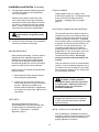
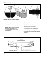
Important Safeguards
The "Warning – Hazardous Voltage" label, shown
in Figure 1-2, is attached to the cover of the
electrical box. The label warns service personnel to
unplug the power supply before attempting any
service work on the case sealer.
This safety alert symbol identifies
important messages in this manual.
READ AND UNDERSTAND THEM BEFORE
INSTALLING OR OPERATING THIS
EQUIPMENT.
Important – In the event the following safety
labels are damaged or destroyed, they must
be replaced to ensure operator safety. For
safety and information replacement labels,
see Parts Illustrations/Lists, Section I, pages
50 and 51.
Figure 1-2 – Electrical Warning Label
The two "Warning – Keep Away From Moving
Belts" labels, shown in Figure 1-1, are located on
the side of the drive belt assemblies at the infeed
end. The labels warn operators and service
personnel to keep hands away from this area when
the drive belts are running.
The "Caution – Pinch Point" label, shown in
Figure 1-3, is attached to the top, infeed end of both
drive belt assemblies. The label reminds operator to
keep hands away from compression rollers when
machine is running.
Figure 1-1 – Hands Warning Label
Figure 1-3 – Pinch Point Caution Label
3
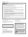
Important Safeguards (Continued)
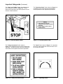
The "Stop" and "Off/On" labels, are attached next
to the switches as shown in Figure 1-4. These
labels remind operators and casual personnel of the
function of these switches.
The "Operating Notice" label, shown in Figure 1-6,
is located on top of both drive belt assemblies to
remind operators of belt adjustment procedures.
Figure 1-4 – Stop and Off/On Labels
Figure 1-6 – Operating Notice Label
The "Safety Instructions" label, shown in
Figure 1-5, is attached to the top of the left drive belt
assembly. The label provides convenient safeguard
instructions for the operator and service personnel.
The "Out/In" label, shown in Figure 1-7, is attached
next to the crank handle that moves the belts in and
out to match box width.
Figure 1-7 – Operating Labels
Figure 1-5 – Safety Instructions Label
4
Important Safeguards (Continued)
The following labels are located on the lower taping
head. Replacement part numbers for these two
labels are listed in Section II.
The "Tape Threading Label" shown in Figure 1-9,
is attached to the left side of the lower taping head.
This label provides a convenient tape threading
diagram. More detailed tape loading and threading
information is provided in the "Operation" section of
this manual.
The "Warning-Sharp Knife" label warns operators
and service personnel of the extremely sharp knife
used to cut the tape at the end of the box sealing
operation. The label, shown in Figure 1-8, is
located on the orange knife guard between the
applying roller assembly and the buffing roller
assembly. Never operate taping head with knife
guard removed.
Before working with the taping head or loading/
threading tape, refer to Figures 3-1 and 3-2, in
Section II, to identify the knife location. Keep hands
out of these areas except as necessary to
service the taping head or to load/thread tape.
Figure 1-9 – Tape Threading Label
Figure 1-8 – Knife Warning Label
5
THIS PAGE IS BLANK
6
Specifications
5. Tape Width:
1. Power Requirements:
Minimum – 36 mm [1-1/2 inches]
Maximum – 48 mm [2 inches]
Electrical – 115 VAC, 60 Hz, 3.8 A
These machines are equipped with an 2.4 m
[8 foot] standard neoprene covered power cord
and a grounded plug.
6. Tape Roll Diameter:
Contact your 3M Representative for power
requirements not listed above.
Up to 405 mm [16 inches] maximum on a
76.2 mm [3 inches] diameter core.
(Accommodates all system roll lengths of
Scotch brand film tapes.)
TM
2. Operating Rate:
Belt speed is 0.40 m/s [78 ft/min]
7. Tape Leg Length (Standard):
3. Operating Conditions:
IMPORTANT SAFEGUARD
Use inIMPORTANT
dry, relativelySAFEGUARD
clean environments at
o
5 to 40o C [40o to 105o F] with clean, dry boxes.
70 mm ± 6 mm [2-3/4 inches ±1/4 inch]
Tape Leg Length (Optional):
Important – Machine should not be washed
down or subjected to conditions causing
moisture
condensation
on components.
IMPORTANT
SAFEGUARD
48 mm ± 6 mm [2 inches ±1/4 inch]
(To change tape leg length to 48 mm [2 inches],
see "Special Set-Up Procedures", page 23.)
4. Tape:
IMPORTANT SAFEGUARD
8. Box Board:
TM
Scotch brand pressure-sensitive film box
sealing tapes.
Style – regular slotted containers – RSC
Bursting test –125 to 275 P.S.I. single wall or
double wall B or C flute.
(Specifications continued on next page)
7
Specifications (Continued)
9. Box Weight and Size Capacities:
Weight
Note: The case sealer is designed to
accommodate most boxes complying with the 1976
FBA and PMMI* voluntary standard "Tolerances for
Top Opening" regular slotted corrugated containers
(RSC). Two of the requirements of the standard are
the following:
Maximum – up to 38.6 kg [85 pounds]
Minimum – contents must support top flaps and
weight must be sufficient to hold bottom flaps
fully closed.
Box Size
MINIMUM
Length –
Width –
Height –
MAXIMUM
Length –
Width –
Height –
The box length is not more than twice the
box width.
The box length is not more than four times
the box depth.
150 mm [6 inches]
115 mm [4-1/2 inches]
120 mm [4-3/4 inches]
DETERMINE THE BOX LIMITATIONS BY
COMPLETING THIS FORMULA:
unlimited
545 mm [21-1/2 inches]
Limited by stability of box
through case sealer
Box Length In
Direction Of Seal
Box Height
Must Be Greater Than .6
If any of the above criteria are not met boxes should
be test run to assure proper machine performance.
* Fibre Box Association, Packaging Machinery
Manufacturer's Association
(Specifications continued on next page.)
8
Specifications (Continued)
Machine Dimensions
W
L
Minimum
mm [Inches] 825 [32-1/2] 920 [36-1/4]
Maximum
mm [Inches]
---
H
A
940 [37]
460 [18]
1220 [48] *
1270 [50]**
--
B
C
610 [24] * 105 [4-3/16]
890 [35] *
--
F
620 [24-1/2]
--
* With drive belt assembly in normal position
** With drive belt assembly in upper position
(See "Special Set-Up Procedure", page 23)
Weight –
approximate 132 kg [290 pounds] crated
approximate 114 kg [250 pounds] uncrated
11.
Set-Up Recommendations:
>
Machine must be level.
>
Customer supplied infeed and exit conveyors (if used) should provide straight and level box entry and exit.
>
Exit conveyors (powered or gravity) must convey sealed boxes away from machine.
9
THIS PAGE IS BLANK
10
Installation and Set-Up
Receiving And Handling
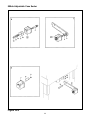
4. Install inclined rollers onto infeed end of each
drive belt assembly. Remove M6 lock nuts (4)
and M6 plain washers (4) from each drive
assembly, position inclined roller on each drive
assembly and fasten with M6 plain washers and
M6 locking nuts. See Figure 2-1.
After the machine has been uncrated, examine the
case sealer for damage that might have occurred
during transit. If damage is evident, file a damage
claim immediately with the transportation company
and also your 3M Representative.
Machine Set-Up
Important – Read "Warnings" on page 16,
before attempting to set-up the case sealer
for operation.
The following instructions are presented in the order
recommended for setting up and installing the case
sealer, as well as for learning the operating
functions and adjustments. Following them step
by step will result in your thorough understanding of
the machine and an installation in your production
line that best utilizes the many features built into the
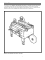
case sealer. Refer to Figure 3-1 to identify the
various components of the case sealer.
Note – A tool kit consisting of metric open end
and hex socket wrenches is provided with the
machine. These tools should be adequate to
set-up the machine, however, other tools
supplied by the customer will be required for
machine maintenance.
Figure 2-1 – Roller Installation
5.
Cut and remove cable tie on lower taping head.
(Applying/buffing rollers are held retracted for
shipment.)
WARNING – Follow this step
carefully as spring pressure is
applied to applying and buffing arms when
cable tie is removed. Keep hands/fingers
AWAY from tape cut-off knife under
orange knife guard. Knife is extremely
sharp and can cause severe injury.
PACKAGING AND SEPARATE PARTS
1. Lift fiberboard cover off pallet after removing
staples at bottom.
2. Remove protective wrapping around machine.
3. Remove hardware that secures case sealer legs
to pallet.
Hold taping head BUFFING ROLLER and cut
and remove cable tie that holds applying/
buffing arms retracted. See Figure 2-2.
Allow buffing/applying arms to extend slowly.
11
Installation and Set-Up (Continued)
6.
Check for free action of lower taping head.
WARNING – Keep hands/fingers
away from tape cut-off knife under
orange knife guard. Knife is extremely
sharp and can cause severe injury.
Push buffing roller into head to check for free,
smooth action of taping head.
7.
Ensure that the tape drum bracket assembly is
mounted straight down, as shown in
Figure 2-3A. The tape drum bracket assembly
can be pivoted to provide clearance or for
retrofit in certain cases.
Outboard tape roll mounting (Alternate Position)Remove the tape drum bracket assembly, stud
spacer and fasteners from the taping head.
Install and secure on the infeed end of the
lower frame, as shown in Figure 2-3B.
Figure 2-2 – Cable Tie, Taping Head
Figure 2-3 – Machine Bed Height Adjustment and Lower Tape Drum Bracket Position
12
Installation and Set-Up (Continued)
8.
TAPE LEG LENGTH
Use appropriate material handling equipment
to remove the machine from the pallet and
move it into position.
Taping heads are pre-set to apply 70 mm
[2-3/4 inch] long tape legs. To change tape legs
to 48 mm [2 inch], see "Special Set-Up
Procedure – Changing Tape Leg Length",
page 23.
Whenever the machine is lifted with a fork
truck, insure that the forks span completely
across the machine frame and do not contact
any wiring or mechanism under the machine
frame. In some cases the lower taping head
may need to be removed to avoid damage.
ELECTRICAL CONNECTION AND CONTROLS
CAUTION – Machine weighs
approximately 114 kg [250 pounds]
uncrated.
9.
The electrical control box, shown in Figure 3-1,
contains the pre-set circuit breaker and can be
located on either side of the machine frame for
customer operating convenience. A standard
three conductor power cord with plug is provided
at the back of the electrical control box for 115
Volt, 60 Hz, 1.9 Amp electrical service. The
receptacle providing this service shall be
properly grounded. Before the power cord is
plugged into 115 Volt, 60 Hz outlet, make sure
that all packaging materials and tools are
removed from the machine. Do not plug
electrical cord into outlet until ready to run
machine.
Continue with the remainder of the installation
and set-up procedure on this page.
MACHINE BED HEIGHT
Adjust machine bed height. The case sealer is
equipped with four adjustable legs that are
located at the corners of the machine frame.
The legs can be adjusted to obtain different
machine bed heights from 610 mm [24 inches]
minimum to 890 mm [35 inches] maximum.
Use of an extension cord is not recommended.
However, if one is needed for temporary use, it
must have a wire size of AWG 16 [1.5 mm dia.],
have a maximum length of 30.5 m [100 ft], and
must be properly grounded.
Refer to Figure 2-3C and set the machine bed
height as follows:
1. Raise and block up the machine frame to
allow adequate leg adjustment.
WARNING – To prevent shock and
fire hazard: Position extension
cord where it will be out of the way of foot
or vehicle traffic. Extension cord is only
for temporary use – do not use for a
permanent installation.
2. Loosen, but do not remove, two M8 x 16
socket head screws in one leg (use M6 hex
wrench). Adjust the leg length for the
desired machine bed height. Retighten the
two screws to secure the leg. Adjust all four
legs equally.
Note – Machines outside the U.S. may be
equipped with 220/240 Volt, 50 Hz systems,
or other electrical requirements compatible
with local practice.
TAPE WIDTH
The taping head has been pre-set to
accommodate 48 mm [2 inch] wide tape rolls.
To adjust heads for narrower tape, refer to
Section II , "Adjustments – Tape Web
Alignment", page 11.
INITIAL START-UP OF CASE SEALER
After completing the "Installation and Set-Up"
procedure, continue through "Operation" for tape
loading and start-up to be sure case sealer is
properly adjusted to run boxes.
13
THIS PAGE IS BLANK
14
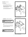
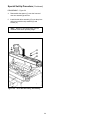
Operation
IMPORTANT – Before operating the case sealer read all the "Important Safeguards", pages 3-5 and
"Warnings", on page 16 as well as all of the "Operation" instructions.
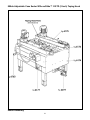
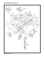
Refer to Figure 3-1 to acquaint yourself with the various components of the case sealer and also see Section II,
page 6, for taping head components.
Figure 3-1 – Case Sealer Components, Left Front View
15
Operation (Continued)
WARNINGS
1. Turn electrical supply off and disconnect before servicing taping head or performing any
adjustments or maintenance on the machine.
2. Turn electrical supply off when machine is not in use.
3. Before turning drive belts on, be sure no tools or other objects are on the machine bed.
4. Keep hands and loose clothing away from moving belts.
5. Never attempt to work on any part of the machine, load tape or remove jammed boxes from
the machine while machine is running.
6. When feeding boxes to the machine by hand, push box in from end only – DO NOT PUSH
WITH HANDS ON ANY CORNER OF THE BOX.
7. Taping head utilizes an extremely sharp tape cut-off knife. The knife is located under the
orange knife guard that has the 'WARNING – SHARP KNIFE" label. Before loading tape, refer
to Section II, page 6, Figure 3-2 to identify the knife location. Keep hands out of this area
except as necessary to service the taping head.
8. Keep hands or loose clothing away from compression rollers on infeed end of machine when
feeding boxes to machine.
9. Failure to comply with these warnings could result in severe personal injury and/or equipment
damage.
Electrical "On/Off" Switch
Tape Loading/Threading
The box drive belts are turned on and off ("Off"
button is red) with the electrical switch on the side of
the machine frame.
See Section II, Pages 7 and 8
Note – If lower tape drum is mounted in
alternate lower outboard position, remove
taping head from machine bed by pulling
straight up, insert threading needle in taping
head and replace taping head. Install tape
roll on drum (adhesive on tape leg up), thread
tape under knurled roller on outboard mount,
then attach tape to threading needle and pull
tape through taping head with threading
needle.
Note – The case sealer has a circuit breaker
located in the electrical enclosure on the lower
right side of the machine frame. If circuit
becomes overloaded and circuit breaker trips,
see "Maintenance – Circuit Breaker", page 20.
Emergency Stop Switch
The machine electrical supply can be turned off by
pressing the latching emergency stop switch. To
restart machine, rotate emergency stop switch
(releases switch latch) and then restart machine by
pressing green (On) button on side of machine
frame.
CAUTION – Taping head weighs
approximately 7.2 kg [16 pounds]
without tape. Use proper body mechanics
when removing or installing taping head.
16
Operation (Continued)
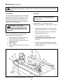
Box Size Set-Up
1. ADJUST DRIVE BELTS (Figure 3-2)
Place a product filled box on infeed conveyor
bed with top flaps folded as shown and
manually move box forward to contact lower
taping head applying roller.
Turn drive belt adjustment crank to position both
side drive belts against sides of box.
Figure 3-2 – Side Drive Belts
2. RUN BOXES TO CHECK ADJUSTMENT
(Figure 3-3)
WARNING – Be sure all packaging
materials and tools are removed
from the machine before operating.
Push electrical switch "On" to start drive belts.
Move box forward until it is taken away by drive
belts.
If the box movement is jerky or stops, move the
side drive belts in slightly to add more pressure
between the box and drive belts.
CAUTION – If drive belts are allowed
to slip on box, excessive belt wear
will occur.
Figure 3-3 – Check Adjustment
17
Operation (Continued)
Box Sealing
1. Feed boxes to machine at minimum 455 mm
[18 inch] intervals.
2. Turn electrical supply "Off" when machine is not
in use.
3. Reload and thread tape as necessary.
4. Be sure machine is cleaned and lubricated
according to recommendations in "Maintenance"
section of this manual.
Notes
1. Machine or taping head adjustments are
described in "Adjustments", Section I for
machine or Section II for taping heads.
2. Box drive motors are designed to run at
a moderate temperature of 40°C [104°F].
In some cases, they may feel hot to the
touch.
18
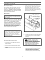
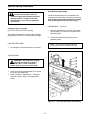
Maintenance
The case sealer has been designed for long,
trouble-free service. The machine will perform best
when it receives routine maintenance and cleaning.
Machine components that fail or wear excessively
should be promptly repaired or replaced to prevent
damage to other portions of the machine or to the
product.
Figure 4-1 illustrates the frame points which should
be lubricated every 250 hours of operation.
Lubricate the rotating and pivoting points, noted by
the arrows, (
) with SAE #30 non-detergent oil.
Note – Wipe off excess oil and grease. It will
attract dust which can cause premature
equipment wear and jamming. Take care
that oil and grease are not left on the surface
of rollers around which tape is threaded, as it
can contaminate the tape's adhesive.
WARNING – Turn off electrical
power supply and disconnect
power cord from electrical supply before
beginning maintenance. If electrical
power is not disconnected, severe injury
to personnel could result.
Taping Head Lubrication – See Section II,
"Maintenance – Lubrication", page 10.
Cleaning
Note – Never attempt to remove dirt from
taping head by blowing it out with compressed
air. This can cause the dirt to be blown inside
the motor and onto sliding surfaces which
may cause premature equipment wear.
Never wash down or subject equipment to
conditions causing moisture condensation on
components. Serious equipment damage
could result.
Regular slotted containers produce a great deal of
dust and paper chips when processed or handled in
equipment. If this dust is allowed to build-up on
machine components, it can cause component wear
and overheating of drive motor. The dust build-up
can best be removed from the machine by a shop
vacuum. Depending on the number and type of
boxes sealed in the case sealer, this cleaning should
be done approximately once per month. If the boxes
sealed are dirty, or if the environment in which the
machine operates is dusty, cleaning on a more
frequent basis may be necessary. Excessive dirt
build-up that cannot be removed by vacuuming
should be wiped off with a damp cloth.
Figure 4-1 – Frame Lubrication Points
Lubrication
Like most other equipment, the taping head must be
properly lubricated to insure long, trouble free
service. Most of the machine bearings are
permanently lubricated and sealed and do not need
to be greased. The drive motor is also permanently
lubricated and does not require additional
lubrication.
Knife Replacement, Taping Head
See Section II, "Maintenance – Knife Replacement",
page 9.
19
Maintenance (Continued)
WARNING – Turn off electrical power and disconnect power cord from electrical supply
before beginning maintenance. If power cord is not disconnected, severe injury to personnel
could result.
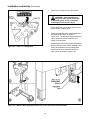
Circuit Breaker
Drive Belts
The case sealer is equipped with a circuit breaker
which trips if the motors are overloaded. Located
inside the electrical enclosure on the side of the
machine frame just below the machine bed, the
circuit breaker has been pre-set at 2.2 amps and
requires no further maintenance.
Note – 3M recommends the replacement of
drive belts in pairs, especially if belts are
unevenly worn.
REPLACEMENT – SEE STEPS 1 THRU 7
TENSION ADJUSTMENT – SEE STEPS 2, 6 AND 7
WARNING – The following
procedure must be performed by
trained service personnel because of the
high voltage electrical hazard within the
control box.
1. Remove and retain the three screws (A), three
washers (B) and side cover (C). See Figure 4-2.
2. Remove and retain the screw (D), washer (E)
and belt tensioner cover (F).
If circuit is overloaded and circuit breaker trips,
unplug machine from electrical power:
3. Turn belt adjustment screws (G)
counterclockwise on both the upper and lower
tension assemblies until belt is loose. See
Figure 4-3.
1. Determine cause of overload and correct.
2. Remove electrical enclosure cover.
3. Press the red "Reset" button and then the
green "Start" button.
4. Replace cover.
5. Plug in machine.
6. Press machine "On" button to resume case
sealing.
4. Locate the belt lacing (joint) by turning the belt
manually. Remove the pin with pliers. Remove
and discard old belt.
Figure 4-2 – Box Drive Belt (Left Side View – Infeed End)
20
Maintenance (Continued)
Figure 4-3 – Box Drive Assembly, Infeed End
5. Install the new belt around drive rollers and
insert new pin. Pin must not extend beyond
edge of belt.
6. To set drive belt tension, turn adjustment screws
(G) equally on both the upper and lower tension
assemblies. Turn the screws clockwise to
increase tension or counterclockwise to
decrease tension. See Figure 4-3.
Important – Before installing new drive belt,
check the belt inside surface for drive
direction arrows and install belt accordingly.
If no arrows are shown, the belt may be
installed either way.
Use a force gauge to pull the belt outward
25 mm [1 inch] at midspan, as shown with a
moderate pulling force of 3.5 kg [7 lbs].
7. Reverse procedures to reassemble the drive belt
assembly.
Figure 4-4 – Box Drive Belt Tension Adjustment, Top View
21
Adjustments
WARNING – Turn off electrical power supply and disconnect power cord from electrical supply
before beginning adjustments. If power cord is not disconnected, severe injury to personnel
could result.
Drive Belt Tension
Tension adjustment of the drive belts may be required during normal operation. Belt tension must be adequate to
positively move the box through the machine and they should run fully on the surface of the pulleys at each end of
the frame. The idler pulleys on the infeed end are adjusted in or out to provide proper belt tension. Each belt is
adjusted separately.
Belt tension is obtained by tightening the adjustment screw so that a moderate pulling force of 3.5 kg [7 lbs]
applied at the midspan, as shown in Figure 4-4, will deflect the belt 25 mm [1 inch]. This will assure positive
contact between the belt and the drive pulley on the discharge end of the taping head.
To adjust belts, see "Maintenance – Drive Belts", page 20.
Taping Head Adjustments
WARNING – Use care when working near tape cut-off knife on taping head as knife is
extremely sharp. If care is not taken, severe injury to personnel could result.
TAPE WEB ALIGNMENT – Section II, page 11
TAPE DRUM FRICTION BRAKE – Section II, page 11
APPLYING MECHANISM SPRING – Section II, page 11
ONE-WAY TENSION ROLLER – Section II, page 12
TAPE LEG LENGTH
Leading Tape Leg Length Adjustment – Section II, page 13
Changing Tape Leg Length from 70 to 48 mm [2-3/4 to 2 Inches] – Section II, page 13.
Note – When changing tape leg to 48 mm [2 inches], refer also to Section I, "Special Set-Up Procedure –
Changing Tape Leg Length", page 23.
22
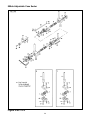
Special Set-Up Procedure
Drive Belt Assembly Height
WARNING – Turn off electrical power
and disconnect power cord from
electrical supply before beginning special
set-up procedure. If power cord is not
disconnected, severe injury to personnel
could result.
The drive belt assemblies can be raised 48 mm
[2 inches] to provide better conveying of tall boxes.
This change increases the minimum box height
that can be taped to 190 mm [7-1/4 inches].
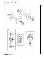
DISASSEMBLE – Figure 5-1
Changing Tape Leg Length
(From 70 to 48 mm [2-3/4 to 2 Inches])
1. Remove and retain the screw (A), cap washer
(B) and spacer (C) from the front and rear arm
assembly pivots.
The following changes to the case sealer will allow
taping boxes 90 mm [3-1/2 inches] minimum height.
2. Lift belt drive assembly (D) up off the arm
assembly pivots.
CASE SEALER FRAME
Note – Keep motor in vertical position to
prevent gear oil from leaking out of motor.
1. No changes to case sealer frame are required.
TAPING HEADS
WARNING – Use care when working
near tape cut-off knife as knife is
extremely sharp. If care is not taken,
severe injury to personnel could result.
1. Lift the lower taping head straight up to remove
it from the case sealer bed.
2. Refer to Section II, Adjustments – Changing
Tape Leg Length", page 13 for taping head
set-up.
Figure 5-1 – Drive Belt Assembly, Disassembly
23
Special Set-Up Procedure (Continued)
REASSEMBLE – Figure 5-2
4. Reassemble the spacer (C) onto the front and
rear arm assembly pivots first.
5. Install the belt drive assembly (D) onto the pivots
and secure with the cap washers (B) and
screws (A).
Note – Both drive belt assemblies must be
installed at the same operating height.
Figure 5-2 – Drive Belt Assembly, Reassembly
24
Troubleshooting
The Troubleshooting Guide lists some possible machine problems, causes and corrections. Also see Section II,
"Troubleshooting", pages 15 and 16 for taping head problems.
Troubleshooting Guide
Problem
Cause
Correction
Drive belts do not convey boxes
Narrow boxes
Check machine specifications.
Boxes are narrower than
recommended, causing slippage
and premature belt wear.
Worn drive belts
Replace drive belts
Taping head applying spring
holder missing
Replace spring holder
Taping head applying spring set
too high
Reduce spring pressure
Worn or missing friction rings
Replace friction rings
Drive belt tension too low
Adjust belt tension
Electrical disconnect
Check power and electrical plug
Circuit breaker not at correct
setting
Set to correct current value
Motor not turning
Evaluate problem and correct
Worn belt
Replace belt
Excessive belt tension
Tension to 3.5 kg [7 lbs] per
adjustment section
Tape drum not centered
Reposition tape drum
Box flaps not of equal length
Check box specifications
Drive belts do not turn
Drive belt break
Tape not centered on box seam
25
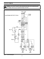
Electrical Diagram
WARNING – Turn off electrical power supply and disconnect power cord from electrical supply
before beginning service. If power cord is not disconnected, personnel could be exposed to
dangerous voltages. Severe injury or equipment damage could result.
Figure 7 – Electrical Diagram
26
Spare Parts/Tools
Spare Parts
The following parts periodically require replacement due to normal wear. They should be ordered immediately
and kept on hand to keep the case sealer in production.
800ab Adjustable Case Sealer, Type 39600
Qty
Section/Ref. No.
1
1
1
2
1
2
2
II/2880-15
II/2886-5
II/2883-2
II/2883-12
II/2886-10
I/6175-58
II/2883-6
Part Number
78-8057-6179-4
78-8057-6178-6
78-8017-9173-8
78-8052-6602-6
78-8070-1273-3
78-8076-5452-6
78-8070-1390-5
Description
Roller – Applying
Roller – Buffing
* Knife – 2.56 Inch [65 mm]
* Spring – Cutter
* Spring – Lower Extension (Black)
Belt – Drive, W/Hook
Spring – Torsion
* Note – These spare parts are supplied with the tool kit that comes with your machine and should also be
ordered separately as used, to keep the case sealer in production.
Tool Kit
A tool and parts kit, part number 78-8060-8476-6 packaged separately and included with your machine, contains
the necessary wrenches for use with the metric fasteners on the case sealer. The threading tool, part number
78-8076-4726-4, contained in the tool kit is available as a stock replacement item and can be ordered separately.
Label Kit
A label kit, part number 78-8113-6745-3 is available as a stock item and contains all the safety and information
labels used on the case sealer or separate labels can be ordered from the parts list, page 51.
27
Options/Accessories
For additional information on the options/accessories listed below, contact your 3M Representative.
Part Number
Option/Accessory
78-8052-6553-1
Box Hold Down Attachment, Model 18500
78-8069-3983-7
Caster Kit Attachment
78-8069-3924-1
Conveyor Extension Attachment
78-8069-3926-6
Low Tape Sensor Kit
78-8079-5560-0
Tape Application Sensor Kit
78-8095-4855-1
2 Inch Tape Edge Fold Kit (Lower)
78-8114-0829-9
AccuGlide™ II STD 2 Inch Lower Taping Head
78-8114-0831-5
AccuGlide™ II STD 3 Inch Lower Taping Head
28
Replacement Parts Illustrations and Parts List
800ab Adjustable Case Sealer, Type 39600
With AccuGlide™ II STD (2 Inch) Taping Head
1. Refer to first illustration, 800ab Assembly, for the Figure Number that identifies a specific portion of the
machine.
2. Refer to the Figure or Figures to determine the individual parts required and the part reference number.
3. The parts list that follows each illustration, includes the part number and part description for the parts in that
illustration.
Note – The complete description has been included for standard fasteners and some commercially
available components. This has been done to allow obtaining these standard parts locally should the
customer elect to do so.
4. Refer to the first page of this instruction manual for replacement parts ordering information.
IMPORTANT – Not all the parts listed are normally stocked items. Some parts or assemblies
shown are available only on a special order basis. Contact 3M/Tape Dispenser Parts to confirm
item availability.
29
THIS PAGE IS BLANK
30
800ab Adjustable Case Sealer W/AccuGlide™ II STD (2 Inch) Taping Head
800ab Assembly
31
800ab Adjustable Case Sealer
Figure 3419
32
Figure 3419
Ref. No.
3M Part No.
Description
3419-1
78-8070-1565-2
Tape Drum Bracket Assembly
3419-2
78-8070-1395-4
Bracket – Bushing Assembly
3419-3
78-8017-9169-6
Nut – M18 x 1
3419-4
78-8060-8474-1
Tape Drum Assembly – 2 Inch Head
3419-5
78-8076-4519-3
Shaft – Tape Drum
3419-6
78-8070-1569-4
Tape Drum Assembly – 2 Inch Wide
3419-7
78-8052-6749-5
Tape Drum Assembly
3419-8
78-8052-6268-6
Leaf Spring
3419-9
26-1002-5753-9
Screw – Self-Tapping
3419-10
78-8060-8172-1
Washer – Friction
3419-11
78-8052-6271-0
Washer – Tape Drum
3419-12
78-8100-1048-4
Spring – Core Holder
3419-13
78-8017-9077-1
Nut – Self-Locking, M10 x 1
3419-14
78-8070-1215-4
Spacer – Stud
3419-15
78-8010-7169-3
Screw – Hex Hd M6 x 12
3419-16
26-1000-0010-3
Washer – Flat M6
3419-17
78-8052-6566-3
Washer – Friction
33
800ab Adjustable Case Sealer
Figure 6163/1 of 2
34
Figure 6163 (page 1 of 2)
Ref. No.
3M Part No.
Description
6163-1
78-8100-1229-0
Shaft Assembly – Drive R/H
6163-2
78-8100-1230-8
Shaft Assembly – Drive L/H
6163-3
78-8076-5401-3
Block – Upper
6163-4
78-8076-5402-1
Block – Lower
6163-5
78-8076-5403-9
Nut – Block, R/H
6163-6
78-8076-5404-7
Nut – Block, L/H
6163-7
78-8076-5405-4
Bushing – Block
6163-8
78-8076-5239-7
Screw – Hex Hd, M6 x 50
6163-9
26-1000-0010-3
Washer – Flat M6
6163-10
26-1003-6916-9
Nut – Locking, Plastic Insert M6
6163-11
78-8100-1220-9
Shaft – Drive Mount
6163-12
26-1003-5842-8
Screw – Hex Hd, M8 x 20
6163-13
78-8017-9318-9
Washer – Plain 8 mm
6163-14
78-8076-5407-0
Screw – R/H
6163-15
78-8076-5408-8
Screw – L/H
6163-16
78-8076-5409-6
Screw – Handle, R/H
6163-17
78-8076-5410-4
Screw – Handle, L/H
6163-18
78-8076-5411-2
Spacer – Screw
6163-19
78-8076-5412-0
Flange – W/Bearing
6163-20
78-8060-8010-3
Snap Ring – 42 mm Shaft
6163-21
78-8076-5413-8
Spring
6163-22
78-8076-5414-6
Coupling – Screw, Female
6163-23
78-8076-5415-3
Coupling – Screw, Male
6163-24
26-1003-7946-5
Screw – Soc Hd, M4 x 25
6163-25
78-8076-5416-1
Spacer – Hex, 10 x 107
6163-26
78-8023-2334-1
Screw – Soc Hd, Hex Soc, M6 x 25
6163-27
78-8076-5417-9
Spacer
35
800ab Adjustable Case Sealer
Figure 6163/2 of 2
36
Figure 6163 (page 2 of 2)
Ref. No.
3M Part No.
Description
6163-28
78-8017-9079-7
Ring – Snap For 15 mm Shaft
6163-29
78-8076-5418-7
Support – Screw
6163-30
26-1003-7949-9
Screw – Soc Hd Hex Soc, M5 x 12
6163-31
78-8005-5741-1
Washer – Plain M5
6163-32
78-8010-7417-6
Nut – Hex M5
6163-33
78-8076-5419-5
Sprocket – 3/8 Inch Z=16
6163-34
78-8046-8135-7
Key – 5 x 5, 12 mm
6163-35
78-8076-5420-3
Chain – 3/8 Inch, 133 Links
6163-36
78-8076-5421-1
Support – Tension Roller
6163-37
78-8010-7169-3
Screw – Hex Hd, M6 x 12
6163-38
78-8070-1503-3
Roller – Chain Tensioning
6163-39
78-8060-7878-4
Idler Screw
6163-40
78-8076-4807-2
Crank Assembly
6163-41
78-8076-5422-9
Crank
6163-42
78-8070-1509-0
Shaft – Crank
6163-43
26-1005-5316-8
Screw – Flat Hd Hex Dr, M5 x 16
6163-44
78-8070-1510-8
Washer – Nylon, 7 x 15 x 1
6163-45
78-8070-1511-6
Bushing
6163-46
78-8005-5740-3
Washer – Plain 4 mm
6163-47
78-8010-7157-8
Screw – Hex Hd, M4 x 10
6163-48
78-8070-1512-4
Knob – VTR-B-M12
6163-49
78-8032-0375-7
Screw – Hex Hd, M6 x 16
6163-50
78-8076-4809-8
Washer – Crank
6163-51
78-8070-1506-6
Cover – Screw
6163-52
78-8076-5423-7
Shaft
6163-53
78-8076-5424-5
Block
6163-54
78-8076-5425-2
Set Screw – M4 x 3
37
800ab Adjustable Case Sealer
Figure 6174/1 of 2
38
Figure 6174 (Page 1 of 2)
Ref. No.
3M Part No.
Description
6174-1
78-8076-5380-9
Bed – Conveyor
6174-2
78-8076-5381-7
Leg Assembly – Inner, W/Stop
6174-3
78-8076-5382-5
Leg – Inner
6174-4
78-8060-8480-8
Pad – Foot
6174-5
78-8055-0867-4
Screw – Hex Hd, M8 x 30
6174-6
78-8017-9313-0
Nut –Self-Locking, M8
6174-7
78-8017-9318-9
Washer – Plain 8 mm
6174-8
78-8076-5383-3
Stop – Leg
6174-9
26-1003-7963-0
Screw – Soc Hd, M8 x 16
6174-10
78-8060-8481-6
Label – Height
6174-11
78-8052-6676-0
Clamp – Outer
6174-12
78-8052-6677-8
Clamp – Inner
6174-13
78-8060-7693-7
Roller – 32 x 38
6174-14
78-8076-5384-1
Shaft – Roller
6174-15
78-8076-5385-8
Spring
6174-16
78-8094-6100-3
Conveyor Assembly – Front
6174-17
78-8076-5387-4
Conveyor – Front
6174-18
78-8091-0780-4
Shaft – Central Roller
6174-19
78-8091-0781-2
Shaft – Side Roller
6174-20
26-1003-5828-7
Screw – Hex Hd, M6 x 10 Special
6174-21
78-8076-5389-0
Mounting – Conveyor
6174-22
78-8094-6101-1
Conveyor Assembly – Rear
6174-23
78-8076-5391-6
Conveyor – Rear
6174-24
78-8076-5392-4
Support – Tape Drum
6174-25
78-8060-8483-2
Support – Outboard Roll
6174-26
78-8060-8484-0
Shaft – Roller
39
800ab Adjustable Case Sealer
Figure 6174/2 of 2
40
Figure 6174 (Page 2 of 2)
Ref. No.
3M Part No.
Description
6174-27
78-8060-8485-7
Roller
6174-28
78-8032-0375-7
Screw – Hex Hd M6 x 16
6174-29
26-1000-0010-3
Washer – Flat M6
6174-30
26-1003-7957-2
Screw – Soc Hd Hex Hd M6 x 16
6174-31
78-8060-8487-3
Cover – Switch
6174-32
78-8060-8087-1
Screw – M5 x 10
6174-33
78-8010-7417-6
Nut – Hex M5
6174-34
78-8076-5393-2
Plate – Tape Bracket Support
6174-35
78-8076-5394-0
Spacer
6174-36
78-8076-5483-1
Support – Roller, Chain Tensioning
6174-37
78-8076-5484-9
Cover – R/H
6174-38
78-8113-6836-0
Cover – L/H, W/English Language Label
6174-39
78-8060-7876-8
Cover – Plug, Lateral
6174-40
78-8028-8208-0
Screw – 6P x 9,5
6174-41
78-8060-7873-5
Plug Female
6174-42
78-8060-8488-1
Screw – Hex Hd M5 x 20
6174-43
78-8046-8217-3
Washer – Special
6174-44
78-8005-5741-1
Washer – Plain M5
6174-45
78-8076-4991-4
Spacer
6174-46
26-1003-5841-0
Screw – M8 x 16
6174-47
78-8076-5192-8
Bracket – E-Stop
6174-48
78-8098-9076-3
Caster Assembly
6174-49
26-1009-9096-4
Caster – Dual Locking
6174-50
26-1009-9094-9
Washer – Spring, Helical, M12
6174-51
26-1009-9095-6
Nut – M12
41
800ab Adjustable Case Sealer
Figure 6175/1 of 2
42
Figure 6175 (page 1 of 2)
Ref. No.
3M Part No.
Description
6175-1
78-8100-1223-3
Side Drive Assembly – R/H W/O Motor
6175-2
78-8100-1224-1
Side Drive Assembly – L/H W/O Motor
6175-3
78-8100-1207-6
Guide – Lower, R/H
6175-4
78-8100-1208-4
Guide – Lower, L/H
6175-5
78-8100-1209-2
Guide – Upper, R/H
6175-6
78-8113-6819-6
Guide – Upper, L/H, W/English Language Label
6175-7
78-8091-0500-6
Bushing – Side Drive
6175-8
78-8055-0661-1
Spacer
6175-9
26-1003-5829-5
Screw – Hex Hd, M6 x 12
6175-10
26-1000-0010-3
Washer – Flat M6
6175-11
78-8094-6109-4
Support – Gearmotor
6175-12
78-8023-2334-1
Screw – Soc Hd, M6 x 25
6175-13
78-8070-1522-3
Gearmotor – Bodine 42X5BFCI-E2, 15:1, 115V, 60 Hz
6175-14
26-1011-8828-7
Capacitor – 15uF, 300VAC, Motor Run
6175-15
78-8070-1523-1
Screw – 1/4 - 28 x 1/2 SHCS
6175-16
78-8094-6174-8
Extension – Gearmotor
6175-17
78-8076-5439-3
Flange Assembly
6175-18
78-8060-7886-7
Screw – Hex Hd, M6 x 16, Special
6175-19
78-8046-8135-7
Key – 5 x 5, 12 mm
6175-20
78-8091-0758-0
Sprocket – 3/8 Inch, Z=14
6175-21
78-8057-5834-5
Tab Washer
6175-22
78-8057-5835-2
Centering Washer
6175-23
78-8076-5440-1
Pulley Assembly – Drive
6175-24
78-8076-5441-9
Roller – Drive
6175-25
78-8052-6713-1
Ring – Polyurethane
6175-26
78-8055-0669-4
Shaft – Pulley Keyed
6175-27
78-8057-5739-6
Key – M5 x 5 x 30 mm
6175-28
78-8055-0668-6
Washer – 15/26 x 1
6175-29
78-8091-0382-9
Belleville Washer – /16
6175-30
78-8076-5442-7
Flange Assembly
6175-31
26-0001-5862-1
Screw – Flat Hd Soc, M5 x 12
6175-32
78-8054-8877-8
Washer – 5,5/20 x 4
6175-33
78-8091-0759-8
Sprocket – 3/8 Inch Z=23
6175-34
78-8076-4933-6
Chain – 3/8 Inch Pitch, 52 Pitch
43
800ab Adjustable Case Sealer
Figure 6175/2 of 2
44
Figure 6175 (page 2 of 2)
Ref. No.
3M Part No.
Description
6175-35
78-8076-5443-5
Pulley Assembly – Idler
6175-36
78-8055-0660-3
Roller – Idler
6175-37
78-8076-5444-3
Shaft – Idler Pulley
6175-38
12-7997-0272-0
E-Ring – M-25
6175-39
78-8076-5445-0
Tensioning – Belt
6175-40
78-8076-5486-4
Screw – M6, Special
6175-41
26-1003-6916-9
Nut – Locking, M6 Plastic Insert
6175-42
78-8076-5446-8
Washer – Shaft
6175-43
78-8070-1519-9
Screw – Soc Hd, Hex Hd,, M8 x 70
6175-44
78-8017-9318-9
Washer – Plain 8 mm
6175-45
78-8076-5448-4
Cover – Belt Tensioner
6175-46
78-8055-0850-0
Screw – Cap, M4 x 6
6175-47
78-8005-5740-3
Washer – Plain 4 mm
6175-48
78-8113-6837-8
Cover – Drive, R/H, W/English Language Label
6175-49
78-8113-6811-3
Cover – Drive, L/H, W/English Language Label
6175-50
26-1002-5753-9
Screw – Self-Tapping
6175-51
78-8100-1213-4
Guard – Belt
6175-52
78-8100-1214-2
Guard – Rubber
6175-53
78-8100-1215-9
Guard – Metal
6175-54
78-8076-5255-3
Screw – Phillips Hd, M4 x 12
6175-55
78-8091-0764-8
Cover – Chain, Right
6175-56
78-8091-0765-5
Cover – Chain, Left
6175-57
78-8010-7165-1
Screw – Flat Hd Soc, M5 x 25
6175-58
78-8076-5452-6
Belt – Box Drive
6175-59
78-8060-7631-7
Connector – 3/8 Inch
6175-60
78-8076-5197-7
Sleeving – /12, 800 mm
6175-61
78-8060-7626-7
Connector – PG 11/12
6175-62
78-8060-7877-6
Plug Housing – Vertical
6175-63
78-8060-7875-0
Plug Male
6175-64
78-8060-8053-3
Wire – 3-Pole, 5 Meters Length
6175-65
78-8076-4968-2
Terminal
6175-66
78-8076-5434-4
Spacer – Drive
6175-67
78-8054-8577-4
Washer – Special
6175-68
26-1001-9843-6
Screw – Flat Soc Hd, M6 x 16
45
800ab Adjustable Case Sealer
Figure 6176
46
Figure 6176
Ref. No.
3M Part No.
Description
6176-1
78-8100-1225-8
Slide Compression Roller – R/H
6176-2
78-8100-1226-6
Slide Compression Roller – L/H
6176-3
78-8113-6984-8
Bracket – Roller, R/H, W/English Language Label
6176-4
78-8113-6985-5
Bracket – Roller, L/H, W/English Language Label
6176-5
78-8076-5491-4
Shaft – Roller
6176-6
78-8060-8106-9
Bushing – Nylon
6176-7
78-8055-0821-1
Rubber Roller
6176-8
78-8052-6566-3
Washer – Friction
6176-9
78-8016-5855-6
E-Ring – 10 mm
6176-10
26-1003-6918-5
Nut – Hex Flange M10, Plastic Insert
47
800ab Adjustable Case Sealer
Figure 6177
48
Figure 6177
Ref. No.
3M Part No.
Description
6177-1
78-8094-6379-3
Support Box
6177-2
78-8113-6759-4
Box – W/English Language Label
6177-3
78-8094-6381-9
Screw – Soc Hd, Hex Hd, M4 x 15
6177-4
78-8005-5740-3
Washer – Plain, 4 mm
6177-5
26-1003-6914-4
Nut – Plastic Insert, M4
6177-6
78-8076-4715-7
Cord Grip
6177-7
78-8076-5211-6
Set Nut – GMP13.5
6177-8
78-8057-5807-1
Cord Grip – ST 16
6177-9
78-8094-6382-7
Guide – Mounting
6177-10
78-8028-8208-0
Screw – 6PX9,5
6177-11
78-8017-9018-5
Washer – Plain, M4 SPEC
6177-12
78-8094-6383-5
Contactor – Sprecher & Schuh, CA4-5-10, 110V, 60HZ
6177-13
78-8076-5378-3
Circuit Breaker – Sprecher & Schuh, KTA-3-25
6177-14
78-8094-6384-3
Clamp – VGPE 4/6
6177-15
78-8076-4968-2
Terminal
6177-16
26-1009-8724-2
Power Cord W/Plug – Type SO
6177-17
78-8100-1038-5
Cable – 3X20 AWG, 5 MT
6177-18
78-8060-8053-3
Wire – 3-Pole, 5 Meters Length
6177-19
26-1003-7957-2
Screw – Soc Hd, Hex Hd, M6 x 16
6177-20
26-1000-0010-3
Washer – Flat, M6
6177-21
78-8119-6528-0
E-Stop Enclosure – W/English Language Label
6177-22
78-8094-6386-8
Switch – On/Off, Sprecher & Schuh, DM3N-C-01/10
6177-23
78-8113-6887-3
Support – On/Off Switch, W/English Language Label
6177-24
78-8017-9257-9
Screw – M4 x 10
6177-25
78-8060-8087-1
Screw – M5 x 10
6177-26
78-8010-7417-6
Nut – Hex, M5
6177-27
78-8094-6385-0
E-Stop – Allen Bradley, 800EP-MTS643LX01
49
800ab Adjustable Case Sealer
Safety and Information Labels
50
800ab Safety and Information Labels
A label kit, part number 78-8113-6745-3, is available as a stock item. It contains all the safety and information
labels used on the case sealer, or labels can be ordered separately from the following list.
Ref. No.
3M Part No.
Description
78-8113-6745-3
Label Kit (Includes items 1 - 13)
1
78-8070-1329-3
Warning – Hazardous Voltage
1
2
78-8070-1366-5
Information – Safety Instructions
1
3
78-8060-8481-6
Information – Leg Height
4
4
78-8062-4266-1
Information – 3M-Matic
2
5
78-8068-3859-1
Information – Service and Spares
1
6
78-8069-3852-6
Information – Ground
2
7
78-8098-8955-9
Information – Out/In, Belt Adjustment
2
8
78-8070-1629-6
Information – Belt tensioning
2
9
78-8095-1141-9
Information – Stop
1
10
78-8070-1330-1
Warning – Moving Belts
1
11
78-8070-1331-9
Warning – Moving Belts
1
12
78-8113-6775-0
Information – Electrical On/Off
1
13
78-8113-6912-9
Caution – Pinch Point
2
51
Qty.