1
DLT8000 Prod. Man. omslag-01
09.01.01
08:01
Side 1
Product Manual
Tandberg DLT8000
Revision 1 - January 2001
352'8&70$18$/
7$1'%(5*'$7$$6$
P.O. Box 134 Kjelsås
N-0411 OSLO, NORWAY
Phone + 47 22 18 90 90
Telefax + 47 22 18 95 50
© Tandberg Data ASA
Part No. 43 22 54-01
Publ. No.
9158-1
January
2001
This publication may describe designs for which patents are granted or pending. By
publishing this information, Tandberg Data ASA conveys no license under any patent or any other rights.
Every effort has been made to avoid errors in text and diagrams. However, Tandberg Data ASA assumes no responsibility for any errors, which may appear in this
publication.
It is the policy of Tandberg Data ASA to improve products as new techniques and
components become available. Tandberg Data ASA therefore reserves the right to
change specifications at any time.
We would appreciate any comments on this publication.
86(50$18$/67$7(0(176)25&/$66$(48,30(17
,17(51$/7$3(6<67(0
This equipment generates, uses, and may emit radio frequency energy. The
equipment has been type tested and found to comply with the limits for a Class A
digital device pursuant to Part 15 of FCC rules, which are designed to provide reasonable protection against such radio frequency interference.
Operation of this equipment in a residential area may cause interference in which
case the user at his own expense will be required to take whatever measures may
be required to correct the interference.
Any modifications to this device - unless expressly approved by the manufacturer can void the user’s authority to operate this equipment under part 15 of the FCC
rules.
127(
Additional information on the need to interconnect the device with shielded (data) cables
or the need for special devices, such as ferrite beads on cables, is required if such
means of interference suppression was used in the qualification test for the device. This
information will vary from device to device and needs to be obtained from the EMC
group or product manager.
:DUQLQJ
7KLV LV D &ODVV $ SURGXFW ,Q D GRPHVWLF HQYLURQPHQW WKLV SURGXFW PD\
FDXVH UDGLR LQWHUIHUHQFH LQ ZKLFK FDVH WKH XVHU PD\ EH UHTXLUHG WR WDNH
DGHTXDWHPHDVXUHV
$FKWXQJ
'LHVHV LVW HLQ *HUlW GHU )XQNVW|UJUHQ]ZHUWNODVVH $ ,Q :RKQEHUHLFKHQ
N|QQHQ EHL %HWULHE GLHVHV *HUlWHV 5XQGIXQNVW|UXQJHQ DXIWUHWHQ LQ
ZHOFKHQ )lOOHQ GHU %HQXW]HU IU HQWVSUHFKHQGH *HJHQPDQDKPHQ
YHUDQWZRUWOLFKLVW
:DUQLQJ
7KLV&ODVV$GLJLWDODSSDUDWXVFRPSOLHVZLWK&DQDGLDQ,&(6
&HW DSSDUHLO QXPpULTXH GH OD FODVVH $ HVW FRQIRUPH j OD QRUPH 10%
GX&DQDGD
$WWHQWLRQ
&HFLHVW XQ SURGXLW GH &ODVVH $ 'DQV XQ HQYLURQQHPHQW GRPHVWLTXH FH
SURGXLWULVTXHGHFUpHUGHVLQWHUIpUHQFHV UDGLRpOHFWULTXHV LO DSSDUWLHQGUD
DORUVjO
XWLOLVDWHXUGHSUHQGUHOHVPHVXUHVVSpFLILTXHVDSSURSULpHV
8VHU0DQXDO6WDWHPHQWVIRU&ODVV$(TXLSPHQW
FRQWLQXHG
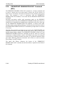
86(50$18$/67$7(0(176)25&/$66%(48,30(17
(;7(51$/7$3(6<67(0
This equipment has been tested and found to comply with the limits for a Class B
digital device, pursuant to Part 15 of the FCC rules. These limits are designed to
provide reasonable protection against harmful interference in a residential installation. Any modifications to this device - unless expressly approved by the manufacturer - can void the user’s authority to operate this equipment under part 15 of the
FCC rules. Operation is subject to the following two conditions: (1) This device may
not cause harmful interference and (2) This device must accept any interference
that may cause undesirable operation.
This equipment generates, uses, and can radiate radio frequency energy and, if not
installed and used in accordance with the instructions, may cause harmful interference to radio communications. However, there is no guarantee that interference will
not occur in a particular installation. If this equipment does cause harmful interference to radio or television reception, which can be determined by turning the
equipment off and on, the user is encouraged to try to correct the interference by
one or more of the following measures:
•
•
•
•
Reorient or relocate the receiving antenna.
Increase the separation between the equipment and receiver.
Connect the equipment into an outlet on a circuit different from that to which the
receiver is connected
Consult the dealer or an experienced radio/TV technician for help.
127(
Additional information on the need to interconnect the device with shielded (data) cables
or the need for special devices, such as ferrite beads on cables, is required if such
means of interference suppression was used in the qualification test for the device. This
information will vary from device to device and needs to be obtained from the EMC
group or product manager.
This Class B digital apparatus complies with Canadian ICES-003.
Cet appareil numérique de la classe B est conforme à la norme NMB-003 du
Canada.
8VHU0DQXDO6WDWHPHQWVIRU&ODVV%(TXLSPHQWFRQWLQXHG
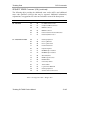
7DEOHRI&RQWHQWV
$ERXW7KLV0DQXDO
$XGLHQFH
3XUSRVH
'RFXPHQW2UJDQL]DWLRQ
&RQYHQWLRQV
*HQHUDO'HVFULSWLRQDQG6SHFLILFDWLRQV
*HQHUDO'HVFULSWLRQ
.H\)HDWXUHV
6SHFLILFDWLRQV
'ULYH&DSDFLW\
,QWHUIDFH7\SH
3HUIRUPDQFHDQG7LPLQJ6SHFLILFDWLRQV
5HOLDELOLW\3URMHFWHG
3K\VLFDO6SHFLILFDWLRQV
7HPSHUDWXUHDQG+XPLGLW\
2SHUDWLQJ$LU9HORFLW\
9LEUDWLRQ6KRFNDQG'URS6SHFLILFDWLRQV
$OWLWXGH
$FRXVWLF(PLVVLRQV
(OHFWURPDJQHWLF(PLVVLRQV
3RZHU5HTXLUHPHQWV
&XUUHQW5HTXLUHPHQWV
7DSH6\VWHP5HFRUGLQJ7\SH
'/7WDSH5HFRUGLQJ0HGLD6SHFLILFDWLRQV
(OHFWURPDJQHWLF,QWHUIHUHQFH(0,6XVFHSWLELOLW\
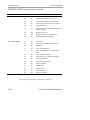
&RQILJXULQJ,QVWDOOLQJDQG2SHUDWLQJWKH7DSH6\VWHP
6DIHW\+DQGOLQJDQG(OHFWURVWDWLF'LVFKDUJH(6'3URWHFWLRQ
6DIHW\3UHFDXWLRQV
+DQGOLQJ
(OHFWURVWDWLF'LVFKDUJH(6'3URWHFWLRQ
&RQILJXULQJDQG,QVWDOOLQJDQ,QWHJUDO7DSH6\VWHP
6HWWLQJWKH6&6,,'
6HWWLQJ7(503:5
6HWWLQJ3DULW\&KHFNLQJ
,QVWDOOLQJWKH7DSH6\VWHP
&RQILJXULQJDQG,QVWDOOLQJD7DEOHWRS7DSH6\VWHP
6HOHFWLQJ6&6,,'
&RQQHFWLQJWKH6&6,%XV&DEOHV
,QVWDOOLQJWKH$&3RZHU&RUG
7KH7DSH&DUWULGJH
&DUHDQG+DQGOLQJRI7DSH&DUWULGJHV
7DQGEHUJ'/73URGXFW0DQXDO
L
7DQGEHUJ'DWD
7DEOHRI&RQWHQWV
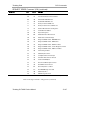
7DSH&DUWULGJH:ULWH3URWHFW6ZLWFK
&KHFNLQJD7DSH&DUWULGJH
/RDGLQJD&DUWULGJH
8QORDGLQJD&DUWULGJH
+RZDQG:KHQWR8VHD&OHDQLQJ7DSH&DUWULGJH
2SHUDWLQJWKH7DSH6\VWHP±&RQWUROVDQG,QGLFDWRUV
8QORDG%XWWRQ
&DUWULGJH,QVHUW5HOHDVH+DQGOH
6HOHFWLQJ'HQVLW\
3RZHU2Q6HOI7HVW3267DQG,QGLFDWRU$FWLYLW\'XULQJ3267
7DSH6\VWHP2SHUDWLQJ0RGHVDQG,QGLFDWRU$FWLYLW\
8VLQJWKH'/77DSH6\VWHP¶V%DVLF+HDOWK&KHFN%+&
7HVW)HDWXUH
7URXEOHVKRRWLQJ
6&6,'HVFULSWLRQ
6&6,2YHUYLHZ
6&6,&RPPDQGV
6LJQDO9DOXHV
6&6,,'%LWV
6&6,6LJQDOV
6&6,6LJQDO'HILQLWLRQV
6LJQDO%XV7LPLQJ
6&6,%XV3KDVHV
%86)5((3KDVH
$5%,75$7,213KDVH
6(/(&7,213KDVH
5(6(/(&7,213KDVH
,QIRUPDWLRQ7UDQVIHU3KDVHV
6&6,%XV&RQGLWLRQV
$WWHQWLRQ&RQGLWLRQ
5HVHW&RQGLWLRQ
4XHXHG8QLW$WWHQWLRQV
0HVVDJHV
0HVVDJH)RUPDW
6XSSRUWHG6&6,0HVVDJHV
$%2570HVVDJHK
%86'(9,&(5(6(70HVVDJH&K
&200$1'&203/(7(0HVVDJHK
',6&211(&70HVVDJHK
,'(17,)<0HVVDJHK))K
,*125(:,'(5(6,'8(0HVVDJHK
,1,7,$725'(7(&7('(55250HVVDJHK
/,1.('&200$1'&203/(7(0HVVDJH$K
/,1.('&200$1'&203/(7(ZLWK)ODJ0HVVDJH
%K
LL
7DQGEHUJ'/73URGXFW0DQXDO
7DQGEHUJ'DWD
7DEOHRI&RQWHQWV
0(66$*(3$5,7<(55250HVVDJHK
0(66$*(5(-(&70HVVDJHK
1223(5$7,21K
5(6725(32,17(560HVVDJHK
6$9('$7$32,17(50HVVDJHK
6<1&+521286'$7$75$16)(55(48(670HVVDJH
K
:,'('$7$75$16)(55(48(670HVVDJHK
6&6,&RPPDQGV
6&6,&200$1'6
6&6,3RLQWHUV
&RPPDQG'HVFULSWRU%ORFN
6WDWXV(UURU5HSRUWLQJ
'$7$3KDVH&RPPDQG&RPSRQHQWV
8QLW$WWHQWLRQ&RQGLWLRQ
%HKDYLRU$W3RZHU2QDQG6&6,%XV5HVHW
'DWD&DFKHDQG7DSH:ULWH,QWHUDFWLRQ
6&6,FRPPDQG'HVFULSWLRQVLQ7KLV0DQXDO
(5$6(&RPPDQGK
,148,5<&RPPDQGK
6WDQGDUG,QTXLU\'DWD3DJH
9HQGRU8QLTXH,QTXLU\'DWD
6XSSRUWHG9LWDO3URGXFW'DWD3DJHVDQG&RPPDQG
6XSSRUW'DWD
/2$'81/2$'&RPPDQG%K
/2&$7(&RPPDQG%K
/2*6(/(&7&RPPDQG&K
/RJ'HWHFWLRQ6XPPDU\LQ/2*6(/(&7&RPPDQG
'HVFULSWRU%ORFN
2SHUDWLRQRI/2*6(/(&7
/RJ6HOHFW3DJH)RUPDW
(UURU'HWHFWLRQ6XPPDU\LQ/RJ6HOHFW3DJHV
/2*6(16(&RPPDQG'K
(UURU'HWHFWLRQ6XPPDU\LQ/2*6(16(&RPPDQG
'HVFULSWRU%ORFN
6XSSRUWHG3DJHV/RJ3DJH3DJHK
5($'3DJHK:5,7(3DJHK(5525/2*
6(16(3DJH
/$67Q(5525(9(1763DJHK
7DSH$OHUW3DJH(K
5($':5,7(&2035(66,213DJHK
'HYLFH:HOOQHVV3DJHK
'HYLFH6WDWXV3DJH(K
02'(6(/(&7&RPPDQGKK
0RGH3DUDPHWHU/LVW
7DQGEHUJ'/73URGXFW0DQXDO
LLL
7DQGEHUJ'DWD
LY
7DEOHRI&RQWHQWV
5($':5,7((55255(&29(5<3$*(K
',6&211(&75(&211(&73$*(K
&21752/02'(3$*($K
'$7$&2035(66,213$*()K
'(9,&(&21),*85$7,213$*(K
0(',803$57,7,213$*(K
7$3($/(573$*(&K
((35209(1'2581,48(3$*((K
&KDQJHDEOH3DUDPHWHUVZLWKLQ02'(6(/(&7
02'(6(16(&RPPDQG$K$K
02'(6(16('DWD+HDGHUV
02'(6(16(%ORFN'HVFULSWRU
02'(6(16(0RGH3DJHV
3(56,67(175(6(59$7,21,1&RPPDQG(K
3(56,67(175(6(59$7,21287&RPPDQG)K
35(9(17$//2:0(',805(029$/&RPPDQG(K
5($'&RPPDQGK
5($'%/2&./,0,76&RPPDQGK
5($'%8))(5&RPPDQG&K
&RPELQHG+HDGHUDQG'DWD0RGH
'DWD0RGH
'HVFULSWRU0RGH
5($'326,7,21&RPPDQGK
6WDQGDUG5($'326,7,21'DWD
7RWDO&XUUHQW/RJLFDO3RVLWLRQ
5(&(,9(',$*1267,&5(68/76&RPPDQG&K
5(/($6(81,7&RPPDQGK
5(/($6(81,7&RPPDQGK
5(3257'(16,7<6833257&RPPDQGK
5(3257/816&RPPDQG$K
5(48(676(16(&RPPDQGK
5(6(59(81,7&RPPDQGK
5(6(59(81,7&RPPDQGK
5(:,1'&RPPDQGK
6(1'',$*1267,&&RPPDQG'K
63$&(&RPPDQGK
7(6781,75($'<&RPPDQGK
9(5,)<&RPPDQGK
:5,7(&RPPDQG$K
:5,7(%8))(5&RPPDQG%K
:ULWH&RPELQHG+HDGHUDQG'DWD0RGHE
:ULWH'DWD0RGHE
'RZQORDG0LFURFRGH0RGHE
'RZQORDG0LFURFRGHDQG6DYH0RGHE
:5,7(),/(0$5.6&RPPDQGK
7DQGEHUJ'/73URGXFW0DQXDO
7DQGEHUJ'DWD
$
7DEOHRI&RQWHQWV
'HILQLWLRQRI9HQGRU8QLTXH6HQVH'DWD,QIRUPDWLRQ
$
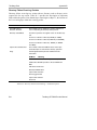
% ((3520UHVLGHQW%XJFKHFNDQG(YHQW/RJV
%
((35203DFNHWV/$67Q(9(176
%
%XJFKHFN3DFNHWV
%
3267)DLOXUH3DFNHWV
%
(YHQW/RJ3DFNHWV
%
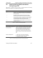
& 8SGDWLQJWKH)LUPZDUH
&
2YHUYLHZ
&
&UHDWLQJD)LUPZDUH8SGDWH7DSH
&
)LUPZDUH8SGDWH3URFHGXUH
&
,QWHUSUHWLQJWKH5HVXOWVRID)LUPZDUH8SGDWH
&
'
5XQQLQJWKH%DVLF+HDOWK&KHFN%+&7HVWYLDWKH/LEUDU\3RUW
'
(
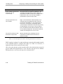
9LVXDO,QVSHFWLRQ3URFHGXUHIRU'/7WDSH&DUWULGJHV
(
)
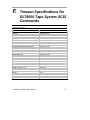
7LPHRXW6SHFLILFDWLRQVIRU'/77DSH6\VWHP6&6,&RPPDQGV
)
* '/7(PXODWLRQ)HDWXUH
*
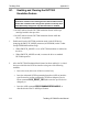
(QDEOLQJDQG&OHDULQJWKH'/7(PXODWLRQ)HDWXUH
*
:KDW<RX6KRXOG.QRZ$ERXWWKH'/7(PXODWLRQ)HDWXUH
*
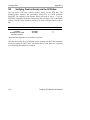
9HULI\LQJ3URGXFW)DPLO\YLDWKH6&6,%XV
*
6&6,%XV'LIIHUHQFHV
*
)URQW3DQHO'LIIHUHQFHV
7DQGEHUJ'/73URGXFW0DQXDO
*
Y
7DQGEHUJ'DWD
7DEOHRI&RQWHQWV
7KLV3DJH,QWHQWLRQDOO\/HIW%ODQN
YL
7DQGEHUJ'/73URGXFW0DQXDO
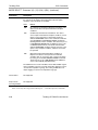
$ERXW7KLV0DQXDO
³$ERXWWKLV0DQXDO´RXWOLQHVWKHVFRSHDQGFRQWHQWVRIWKLVPDQXDO,WFRQWDLQVLQIRUPDWLRQ
DERXWWKHLQWHQGHGDXGLHQFHSXUSRVHRIWKHPDQXDOGRFXPHQWRUJDQL]DWLRQDQGGRFXPHQW
FRQYHQWLRQV
$XGLHQFH
This manual is written for original equipment manufacturers (OEMs) that are
integrating this Tandberg DLT8000 system into a host system or subsystem. Its
primary audience is the OEM technical staff that makes tape system purchase and
configuration decisions, and system integrators that are responsible for the SCSI
interface. Additionally, the manual can be used by technically astute end-users for
installation and operation of the tape system, although that is a secondary
audience.
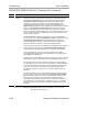
3XUSRVH
This manual describes the Tandberg DLT8000 Tape System. It is intended to
provide the information necessary to integrate the tape system into a computer
system or subsystem.
'RFXPHQW2UJDQL]DWLRQ
This product manual contains five chapters, a number of appendixes of related
useful information, and an index. It includes an overview of the Small Computer
System Interface (SCSI) and detailed descriptions of the messages and SCSI
commands as used by the tape system. The manual is organized as follows:
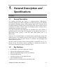
&KDSWHU
*HQHUDO'HVFULSWLRQDQG6SHFLILFDWLRQV
This chapter contains a brief description of and specifications for the
system.
&KDSWHU
&RQILJXUDWLRQDQG,QVWDOODWLRQ
This chapter contains information on system hardware and system
interfaces.
7DQGEHUJ'/73URGXFW0DQXDO
7DQGEHUJ'DWD
&KDSWHU
$ERXW7KLV0DQXDO
6&6,'HVFULSWLRQ
This chapter provides a detailed description of the logical interfaces
of the tape system. It describes the product’s compliance with the
ANSI SCSI-2 specification. The system’s many optional features are
described here and throughout the manual.
&KDSWHU
6&6,0HVVDJHV
This chapter provides a list and description of most messages supported by the tape system. The SCSI message system allows communication between SCSI initiators and SCSI targets (the tape
system, in this case) for interface management and for command
elaboration and qualification.
&KDSWHU
6&6,&RPPDQGV
This chapter describes in detail each command supported by the tape
system. The SCSI command system enables an initiator to direct a
tape system to perform a wide range of operational and diagnostic
functions.
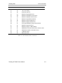
$SSHQGL[$ 'HILQLWLRQRI9HQGRU8QLTXH6HQVH'DWD,QIRUPDWLRQ
Appendix A provides a list of internal status codes related to the
REQUEST SENSE SCSI command.
$SSHQGL[% 6HQVH.H\,QIRUPDWLRQ
Appendix B provides a list of tape system additional sense codes,
additional sense code qualifiers, and their meanings.
$SSHQGL[& ((35205HVLGHQW%XJFKHFNDQG(YHQW/RJV
Appendix C provides an explanation of the event logs stored in
semi-permanent, non-volatile memory.
$SSHQGL[' 8SGDWLQJWKH)LUPZDUH
Appendix D provides a step-by-step procedure for updating a tape
system’s PCBA controller-resident firmware.
7DQGEHUJ'/73URGXFW0DQXDO
7DQGEHUJ'DWD
$ERXW7KLV0DQXDO
$SSHQGL[( 5XQQLQJWKH%DVLF+HDOW&KHFN%+&7HVW9LDWKH/LEUDU\3RUW
Appendix E explains how a trained service provider can run the
DLT8000 tape system’s BHC test on a tape drive that is configured
as a component within a library.
$SSHQGL[) 9LVXDO,QVSHFWLRQ3URFHGXUHIRU'/7WDSH&DUWULGJHV
Appendix F explains how to visually inspecct a DLTtape cartridge.
Damaged tape cartridges must not be used.
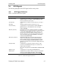
&RQYHQWLRQV
This manual uses the following conventions to designate specific elements:
(OHPHQW
&RQYHQWLRQ
([DPSOH
Commands
Uppercase (unless case-sensitive)
FORMAT UNIT
Messages
Uppercase
INVALID PRODUCT
NUMBER
Hexadecimal Notation
Number followed by lowercase K
25h
Binary Notation
Number followed by lowercase E
101b
Decimal Notation
Number without suffix
512
Acronyms
Uppercase
POST
Abbreviations
Lowercase, except where standard
usage requires uppercase
Mb (megabits)
MB (megabytes)
7DQGEHUJ'/73URGXFW0DQXDO
7DQGEHUJ'DWD
$ERXW7KLV0DQXDO
7KLV3DJH,QWHQWLRQDOO\/HIW%ODQN
7DQGEHUJ'/73URGXFW0DQXDO
*HQHUDO'HVFULSWLRQDQG
6SHFLILFDWLRQV
7KLVFKDSWHUSURYLGHVDGHVFULSWLRQDQGJLYHVVSHFLILFDWLRQVIRUWKH7DQGEHUJ'/7
7DSH6\VWHP
*HQHUDO'HVFULSWLRQ
The Tandberg DLT8000 tape system is a high-performance, high-capacity,
streaming cartridge tape product designed for efficient data back-up for midrange
and high-end computing systems. With Tandberg Data’s DLT advanced linear
recording technology, a highly accurate tape guide system, and an adaptive control
mechanism, the system is ideally suited for mid-range systems, network servers,
and high-end workstations and systems.
Using data compression and compaction, the DLT8000 tape system features a
formatted capacity of 80.0 GB* and a sustained user data transfer rate of up to 12
MB/second* (native capacity is 40.0 GB; native data transfer rate is 6.0
MB/second).
The device is an extended-length, 5.25 inch form factor, half-inch tape system. The
design includes a four channel read/write head, Lempel-Ziv (LZ) high-efficiency
data compression, and tape mark directory to maximize data throughput and
minimize data access time.
The tape system is available either as an integrated or “embedded” drive or as a
tabletop version. The tabletop version is packaged in a housing and includes its
own cooling fan and power supply, requiring ac power.
•
•
•
•
•
•
.H\)HDWXUHV
40.0 GB Native, 80.0 GB Compressed* Capacity
Superior Error Detection and Correction
Extensive Embedded Diagnostic/Self-Test Software
Dual Speed Recording
Fast access to Data via Tape Mark Directory
Tape-Loadable Firmware
* Actual transfer rate and capacity will vary depending on data.
7DQGEHUJ'/73URGXFW0DQXDO
7DQGEHUJ'DWD
*HQHUDO'HVFULSWLRQDQG6SHFLILFDWLRQV
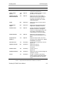
6SHFLILFDWLRQV
This section of Chapter 1 provides the performance, physical, environmental, and
electrical specifications for the tape system. Specifications for the DLTtape tape
media cartridges are included.
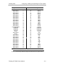
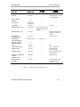
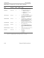
'ULYH&DSDFLW\
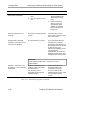
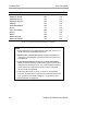
Table 1−1 provides the ranges of capacity (native and compressed) for the tape
system, depending on which DLTtape cartridge is used.
'/7WDSH&DUWULGJH
/HQJWKRI0HGLXP
6WRUDJH&DSDFLW\
1DWLYH
6WRUDJH&DSDFLW\
&RPSUHVVHG
DLTtape IV
(1800 foot tape)
40.0 GB User Data
80.0 GB User Data*
DLTtape IIIXT
(1800 foot tape)
15.0 GB User Data
30.0 GB User Data*
DLTtape III
(1200 foot tape)
10.0 GB User Data
20.0 GB User Data*
$FWXDOFDSDFLW\ZLOOYDU\GHSHQGLQJRQGDWD
7DEOH−6WRUDJH&DSDFLW\
,QWHUIDFH7\SH
Two interfaces are available: Low Voltage Differential (LVD)/Single-Ended and
High Voltage Differential (HVD) SCSI-2.
7DQGEHUJ'/73URGXFW0DQXDO
7DQGEHUJ'DWD
*HQHUDO'HVFULSWLRQDQG6SHFLILFDWLRQV
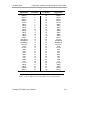
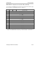
3HUIRUPDQFHDQG7LPLQJ6SHFLILFDWLRQV
Table 1−2 provides performance and timing specifications for the tape system.
,WHP
6SHFLILFDWLRQ
Transfer Rates
User Native = 6.0 MB/second
Compresseed = Up to 12.0
MB/second *
Error Rates
Recoverable READ Error Rate =
6
1 in 10 bits read
Unrecoverable READ Error Rate = 1
17
in 10 bits read **
Undetected READ Error Rate = 1 in
27
10 bits read
Tracks
208 physical (52 quad logical tracks
on media); drive has 4 parallel
physical (1 logical) tracks written or
read simultaneously
Linear Bit Density
98,250 bpi per track
READ / WRITE Tape Speed
168 inches/second
Rewind Tape Speed
175 inches/second
Linear Search Tape Speed
175 inches/second
Average Rewind Time
60 seconds
* =
Depending on data type and SCSI bus limitations/system configuration
** =
An unrecoverable error is any READ error that cannot be recovered using the
drive’s internal error recovery algorithms or, if the drive indicates “Cleaning
Required”, by removing the data cartridge, performing a cleaning operation, and
attempting to re-read the data from the data cartridge.
7DEOH−3HUIRUPDQFHDQG7LPLQJ6SHFLILFDWLRQV
7DQGEHUJ'/73URGXFW0DQXDO
7DQGEHUJ'DWD
*HQHUDO'HVFULSWLRQDQG6SHFLILFDWLRQV
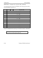
,WHP
6SHFLILFDWLRQ
READ/WRITE Tape Speed
168 inches/second
Linear Search Tape Speed
175 inches/second
Rewind Tape Speed
175 inches/second
Average Rewind Time
60 seconds
Maximum Rewind Time
120 seconds
0LQLPXP
$YHUDJH
0D[LPXP
Access Time From BOT
(32KB blocks) in seconds
2
69
136
Save Set Access Times
(25 Mb Save Set) in seconds
6
70
134
LOAD Time to BOT
(Formatted tape)
$YHUDJH
130 seconds (steady state)
LOAD Time to BOT
(Unformatted tape)
in seconds
$YHUDJH
133 seconds (steady state)
UNLOAD Time From BOT
$YHUDJH
21 seconds
7DEOH−3HUIRUPDQFHDQG7LPLQJ6SHFLILFDWLRQVFRQWLQXHG
7DQGEHUJ'/73URGXFW0DQXDO
7DQGEHUJ'DWD
*HQHUDO'HVFULSWLRQDQG6SHFLILFDWLRQV
5HOLDELOLW\3URMHFWHG
Mean time between failures (MTBF) for the tape system is projected to be 250,000
hours at 100% duty cycle, not including heads; 300,000 hours at 20% duty cycle,
not including heads. Life of recording heads is 30,000 hours, minimum; 50,000
hours, average.
Media durability is projected to be 1,000,000 passes of the tape medium across the
read/write heads (15,000 uses). One tape pass is defined as any point on the tape
passing the head in either direction.
Tandberg Data does not warrant that predicted MTBF is representative of any
particular unit installed for customer use. Actual figures vary from unit to unit.
3K\VLFDO6SHFLILFDWLRQV
Table 1−3 provides the key physical specifications for the integratible and tabletop
versions of the tape system.
'HVFULSWLRQ
,QWHJUDWLEOH9HUVLRQ
7DEOHWRS9HUVLRQ
Height
3.25 in. (82.5 mm) without
front bezel; 3.4 in (86.3 mm)
with front bezel.
6.48 in. (164.592 mm)
Width
5.735 in. ± .045 in. (144.8 mm
± 1.143 mm) behind front
bezel; 5.87 in (149.0 mm) with
front bezel.
6.88 in. (174.752 mm)
Length
9.00 in. (228.6 mm) measured
from back of front bezel; 9.60
in. (243.8 mm) including front
bezel
12.8 in. (325.12 mm) (includes
the Tape Eject Handle
protruding 0.2 inches [5.08
mm])
Weight
6 lb, 7 oz (2.9 kg)
14 lbs (6.35 kg)
7DEOH−3K\VLFDO'LPHQVLRQV
7DQGEHUJ'/73URGXFW0DQXDO
7DQGEHUJ'DWD
*HQHUDO'HVFULSWLRQDQG6SHFLILFDWLRQV
7HPSHUDWXUHDQG+XPLGLW\
Table 1−4 provides the temperature and humidity specifications for the tape
system.
'HVFULSWLRQ
,QWHJUDWLEOH9HUVLRQ
7DEOHWRS9HUVLRQ
Temperature Range
50°F to 104°F (10°C to 40°C)
50°F to 104°F (10°C to 40°C)
Temperature Gradient
18°F (10°C ) per hour (across
the range)
18°F (10°C ) per hour (across
the range)
Dry Bulb Temp. Range
50°F to 104°F (10°C to 40°C)
50°F to 104°F (10°C to 40°C)
Wet Bulb Temperature
77°F (25°C)
77°F (25°C)
Relative Humidity
20% to 80%, non-condensing
20% to 80%, non-condensing
Humidity Gradient
10% / hour
10% / hour
2SHUDWLQJ5DQJHV
6WRUDJH5DQJHV8QSDFNHGRU3DFNHG
Temperature Gradient
36°F (20°C ) per hour with 5°
margin (across the range)
36°F (20°C ) per hour with 5°
margin (across the range)
Dry Bulb Temp. Range
-40°F to 150.8°F (-40°C to
66°C)
-40°F to 150.8°F (-40°C to
66°C)
Wet Bulb Temperature
114.8°F (46°C)
114.8°F (46°C)
Relative Humidity
5% to 95%, non-condensing
5% to 95%, non-condensing
Humidity Gradient
10% / hour
10% / hour
Temperature Gradient
36°F (20°C ) per hour with 5°
margin (across the range)
36°F (20°C ) per hour with 5°
margin (across the range)
Dry Bulb Temp. Range
-40°F to 150.8°F (-40°C to
66°C)
-40°F to 150.8°F (-40°C to
66°C)
6KLSSLQJ5DQJHV
Wet Bulb Temperature
114.8°F (46°C)
114.8°F (46°C)
Relative Humidity
10% to 95%, non-condensing
10% to 95%, non-condensing
Humidity Gradient
10% / hour
10% / hour
7DEOH−7HPSHUDWXUHDQG+XPLGLW\6SHFLILFDWLRQV
7DQGEHUJ'/73URGXFW0DQXDO
7DQGEHUJ'DWD
*HQHUDO'HVFULSWLRQDQG6SHFLILFDWLRQV
2SHUDWLQJ$LU9HORFLW\
Both versions of the tape system require an air flow velocity of 125 linear feet per
minute measured directly in front of the bezel.
9LEUDWLRQ6KRFNDQG'URS6SHFLILFDWLRQV
Table 1−5 provides the vibration and shock specifications for operating tape
systems, and for non-operating tape systems (both packaged and unpackaged).
Table 1-6 provides the drop specifications for the tape system.
2SHUDWLQJ9LEUDWLRQ6SHFLILFDWLRQV
Vibration Type
Sine
Sweep
Frequency Range
5 – 500 – 5 Hz
Upward and downward
sweep
Acceleration Level
0.25 G
Between 22 and 500 Hz
0.010” DA
Between 5 and 22 Hz
(crossover)
X, Y, and Z axes
Sweep rate: 1 octave per
minute
Application
2SHUDWLQJ6KRFN6SHFLILFDWLRQV
Pulse Shape
½ sine pulse
Peak Acceleration
10 G
Duration
10 ms
Application
X, Y, and Z axes; once in each axis
1RQ2SHUDWLQJ3DFNDJHG9LEUDWLRQ6SHFLILFDWLRQV
Vibration Type
Random Vibration
Frequency Range
5 to 300 Hz, Vertical Axis (Z); 5 to 200 Hz, Horizontal
Axes (X and Y)
Vibration Levels
1.0 GRMS overall in X, Y, and Z axes
Application
X, Y, and Z axes (one hour, each axis; 3 hour total)
7DEOH−9LEUDWLRQDQG6KRFN6SHFLILFDWLRQVFRQWLQXHG
7DQGEHUJ'/73URGXFW0DQXDO
7DQGEHUJ'DWD
*HQHUDO'HVFULSWLRQDQG6SHFLILFDWLRQV
1RQ2SHUDWLQJ8QSDFNDJHG9LEUDWLRQ6SHFLILFDWLRQV
Vibration Type:
Sine
Sweep
Frequency Range
5 – 500 – 5 Hz
Upward and downward sweep
Acceleration Level
1G
5 – 500 – 5 Hz
Application
X, Y, and Z axes
Sweep rate: 1 octave per minute
0.010 inch DA
Between 5 – 31 Hz (crossover)
Vibration Type:
Random
Frequency Range
10 – 500 Hz
Acceleration Level
2g
PSD Envelope
0.008 g^2/Hz
Application
X, Y, and Z axes
60 minutes/axis
1RQ2SHUDWLQJ3DFNDJHG5HSHWLWLYH6KRFN6SHFLILFDWLRQV
Excitation Type
Synchronous vertical motion; 1 inch excursion
Shock (Bounce) Cycles
14,200 total
Application
Half cycles each in X and Y orientations; ½ 7100 impacts in the
shipping orientation, 3500 impacts in the remaining two axes.
1RQ2SHUDWLQJ8QSDFNDJHG6KRFN6SHFLILFDWLRQV
Pulse Shape: Square wave
Peak Acceleration
40 G
Duration
10ms/180 inches/second
Application
X, Y, and Z axes, twice in each axis (once each direction)
Pulse Shape: ½ sine pulse
Peak Acceleration
140 G
Duration
2 ms
Application
X, Y, and Z axes, twice in each axis (once each direction)
7DEOH−9LEUDWLRQDQG6KRFN6SHFLILFDWLRQVFRQWLQXHG
7DQGEHUJ'/73URGXFW0DQXDO
7DQGEHUJ'DWD
*HQHUDO'HVFULSWLRQDQG6SHFLILFDWLRQV
1RQ2SHUDWLQJ3DFNDJHG'URS6SHFLILFDWLRQV
Test Type: Drop Shock
Drop Height:
30 inches for items < 20.9 lbs (9.48 kg)
23 inches for items between 21lbs (9.52 kg) and 40.9
lbs. (18.55 kg)
Application
10 drops total; 1 each side, 3 edges, 1 corner
7DEOH−'URS6SHFLILFDWLRQV
$OWLWXGH
The following table provide the tape system’s altitude specifications, both
operating and non-operating.
2SHUDWLQJ1RQ2SHUDWLQJ$OWLWXGH6SHFLILFDWLRQV
- 500 ft (-152 m) to 40,000 ft (12192 m) at ambient temperature of 77ºF (25ºC)
7DEOH−$OWLWXGH6SHFLILFDWLRQV
.
7DQGEHUJ'/73URGXFW0DQXDO
7DQGEHUJ'DWD
*HQHUDO'HVFULSWLRQDQG6SHFLILFDWLRQV
$FRXVWLF(PLVVLRQV
The following tables provide the tape system’s acoustic noise emission levels, both
as noise power and sound pressure. Information about acoustic emissions is also
provided in German to fulfill an international requirement.
1RLVH3RZHU(PLVVLRQ/HYHO/13(F
0RGH
Idle
,QWHJUDWLEOH9HUVLRQ
7DEOHWRS9HUVLRQ
Not applicable
5.4 Bel
5.9 Bel
5.9 Bel
Streaming
6RXQG3UHVVXUH/HYHO/3$F
0RGH
Idle
,QWHJUDWLEOH9HUVLRQ
7DEOHWRS9HUVLRQ
Not applicable
40 dB
47 dB
44 dB
Streaming
7DEOH−$FRXVWLF1RLVH(PLVVLRQV1RPLQDO
6FKDOOHPLVVLRQVZHUWH±:HUWHDQJDEHQQDFK,62XQG,62',1(1
6FKDOOGUXFNSHJHO
*HUlW
6FKDOOHLVWXQJVSHJHO
/S$PG%$
/Z$'%
=XVFKDXHUSRVLWLRQHQ
/HHUODXI
THxxx *
THxBx *
•
%HWULHE
/HHUODXI
5,9
5,4
%HWULHE
47
5,9
40
44
= THxxx is the integratible version of the tape system; THxBx is the tabletop version.
7DEOH−$FRXVWLF1RLVH'HFODUDWLRQIRU*HUPDQ1RLVH'HFODUDWLRQ/DZ
(OHFWURPDJQHWLF(PLVVLRQV
The tabletop version complies with FCC Class B limits.
7DQGEHUJ'/73URGXFW0DQXDO
7DQGEHUJ'DWD
*HQHUDO'HVFULSWLRQDQG6SHFLILFDWLRQV
3RZHU5HTXLUHPHQWV
Table 1−10 provides the applicable power requirements for both versions of the
tape system. Note that the tabletop version requires ac power.
'HVFULSWLRQ
Electrical
Ranging)
Rating
Power Requirements
(Auto
,QWHJUDWLEOH9HUVLRQ
7DEOHWRS9HUVLRQ
Not applicable
100 to 240 VAC
28 W, steady state
56 W, maximum
2.8 A, steady state;
Not Applicable
Power Consumption:
+5 V (±5%) bus *
4.35 A, maximum
+12 V (±5%) bus *
1.2 A, steady state;
Not Applicable
4.5 A, maximum
7DEOH−3RZHU5HTXLUHPHQWV
* = Voltage measured at the power bus connector pins.
7DQGEHUJ'/73URGXFW0DQXDO
7DQGEHUJ'DWD
*HQHUDO'HVFULSWLRQDQG6SHFLILFDWLRQV
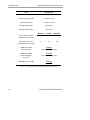
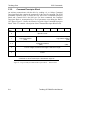
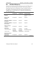
&XUUHQW5HTXLUHPHQWV
Table 1-11 presents the current requirements for the tape system in a variety of
operating conditions. These numbers may vary with workload.
Drive Operating in WRITE Mode Start/Stop
Typical
Maximum (Includes Ripple)
5 Volt
2.2
3.9
12 Volt
1.2
3.6
Drive Operating in Calibration
Typical
Maximum (Includes Ripple)
5 Volt
2.1
3.3
12 Volt
1.2
4.5
Drive Tensioned, but Tape Not in Motion (Standby Mode)
Typical
Maximum (Includes Ripple)
5 Volt
2.2
2.7
12 Volt
0.6
1.0
Drive Unloaded with Cartridge Door Opened
Typical
Maximum (Includes Ripple)
5 Volt
2.1
2.6
12 Volt
0.6
1.1
Typical
Maximum (Includes Ripple)
Drive Rewinding to BOT
5 Volt
2.3
3.6
12 Volt
0.8
3.0
Typical
Maximum (Includes Ripple)
Drive Operating in Stream WRITE/READ Mode
5 Volt
3.1
4.3
12 Volt
1.0
3.6
7DEOH−&XUUHQW5HTXLUHPHQWV
7DQGEHUJ'/73URGXFW0DQXDO
7DQGEHUJ'DWD
*HQHUDO'HVFULSWLRQDQG6SHFLILFDWLRQV
7DSH6\VWHP5HFRUGLQJ7\SH
The tape system uses 2,7 RLL code with DLTTM 2000, DLTTM 2000XT,
DLTTM 4000, DLTTM 7000, or DLT8000 format.
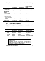
'/7WDSH5HFRUGLQJ0HGLD6SHFLILFDWLRQV
Table 1−12 provides specifications for tape media. Table 1-12 provides operating
and storage enviroment limits for the tape cartridges
'/7WDSH0HGLD7\SH
'/7WDSH,,,
'/7WDSH,,,;7
6SHFLILFDWLRQV
Width: 0.5 inch
Length:
1200 feet
Cartridge Dimensions:
4.1 in x 4.1 in x 1.0 in
Shelf Life:
20 years min. @ 20°C & 40%
RH (non-condensing)
Usage:
500,000 passes
Width:
0.5 inch
Length:
1800 feet
Cartridge Dimensions:
4.1 in x 4.1 in x 1.0 in
Shelf Life:
30 years min. @ 20°C & 40%
RH (non-condensing)
Usage:
500,000 passes
7DEOH−'/7WDSH0HGLD6SHFLILFDWLRQV
7DQGEHUJ'/73URGXFW0DQXDO
7DQGEHUJ'DWD
*HQHUDO'HVFULSWLRQDQG6SHFLILFDWLRQV
'/7WDSH0HGLD7\SH
'/7WDSH,9
6SHFLILFDWLRQV
Width: 0.5 inch
Length:
1800 feet
Cartridge Dimensions:
4.1 in x 4.1 in x 1.0 in
Shelf Life:
30 years min. @ 20°C & 40%
RH (non-condensing)
Usage:
1,000,000 passes
7DEOH−'/7WDSH0HGLD6SHFLILFDWLRQVFRQWLQXHG
2SHUDWLQJ&RQGLWLRQV
Temperature
50° to 104°F (10° to 40°C)
Relative Humidity
20% to 80% noncondensing
6WRUDJH&RQGLWLRQV
:LWK'DWD
:LWKRXW'DWD
Temperature
64° to 79°F (18° to 26°C)
61° to 89°F (16° to 32°C)
Relative Humidity
40% to 60% noncondensing
20% to 80% noncondensing
7DEOH−'/7WDSH&DUWULGJH2SHUDWLQJDQG6WRUDJH/LPLWV
7DQGEHUJ'/73URGXFW0DQXDO
7DQGEHUJ'DWD
*HQHUDO'HVFULSWLRQDQG6SHFLILFDWLRQV
(OHFWURPDJQHWLF,QWHUIHUHQFH(0,6XVFHSWLELOLW\
This section presents tables that provide the specifications for conducted
emissions, radiated emissions, magnetic radiated susceptibility, radiated
susceptibility, conducted susceptibility, and ESD failure limits.
Regulations and certifications for the tape system include:
)RUHOHFWURPDJQHWLFHPLVVLRQV
•
•
CSA 108.8
EEC Directive 89/336
(1DQGQDWLRQDOVWDQGDUGVDUHEDVHGRQ
•
•
•
•
BS6527 (UK)
NEN55022 (Netherlands)
VDE 0971 Class B (Germany)
CE Mark
&LVSU&ODVV%
•
•
FCC Rules Part 15B
Class B Certification
127(
Limits for Class B equipment are in the frequency range from 0.15 to 30
MHz. The limit decreases linearly, with the logarithm of the frequency in
the range from 0.15 to 0.50 MHz.
)UHTXHQF\5DQJH0+]
/LPLWVG%
4XDVL3HDN
$YHUDJH
0.15 to 0.05
66 to 56*
56 to 46
0.50 to 5
56
46
5 to 30
60
50
*
The limit decreases with the logarithm of the frequency.
7DEOH−&RQGXFWHG(PLVVLRQV
7DQGEHUJ'/73URGXFW0DQXDO
7DQGEHUJ'DWD
*HQHUDO'HVFULSWLRQDQG6SHFLILFDWLRQV
127(
Table 1-15 shows the Class B equipment limits for radiated interference
field strength in the frequency range from 30 MHz to 30 GHz at a test
distance of 3 and 10 meters.
)UHTXHQF\5DQJH0+]
4XDVL3HDN/LPLWG%µ9P
#0HWHUV
#0HWHUV
30 to 230
40
30
230 to 1000
46
37
Above 1000
54
N/A
7DEOH−5DGLDWHG(PLVVLRQV
/RZ)UHTXHQF\0DJQHWLF)LHOGVWRN+]
100 dB (pt) @ 10 kHz Declining
to 80 dB (pt) @ 1 MHz
No errors, no screen distortion
7DEOH−0DJQHWLF5DGLDWHG6XVFHSWLELOLW\
+LJK)UHTXHQF\(OHFWULF)LHOGVWR0+]
3 V/m (rms) 80% modulated
1 kHz
No errors, no screen distortion
S/W recoverable errors
No hardware failure
7DEOH−5DGLDWHG6XVFHSWLELOLW\
7DQGEHUJ'/73URGXFW0DQXDO
7DQGEHUJ'DWD
*HQHUDO'HVFULSWLRQDQG6SHFLILFDWLRQV
127(
The transient voltage is the actual peak voltage above the normal ac
voltage from the power source.
)DVW7UDQVLHQW%XUVWVIRU3RZHUDQG'DWD&DEOHV
2 kV
S/W recoverable errors
No hardware failures
+LJK(QHUJ\7UDQVLHQW9ROWDJHIRU3RZHU&DEOHV
1.2 kV
No errors
2.5 kV
S/W recoverable errors
No hardware failures
/RZ/HYHO&RQGXFWHG,QWHUIHUHQFH
3 V (rms) 80% modulated
kHz
1
No errors
S/W recoverable errors
No hardware failures
)DVW7UDQVLHQW%XUVWVIRU3RZHUDQG'DWD&DEOHV
2 kV
S/W Recoverable errors
No hardware failures
7DEOH−&RQGXFWHG6XVFHSWLELOLW\
)DLOXUH7\SH
(TXLSPHQW
)DLOXUH/HYHO
Hard
Office
1 to 12 kV
Hardware
Office
Up to 15 kV
$OORZDEOH(UURUV
No Operator Intervention (soft
recoverable allowed)
No component damage – operator
intervention allowed (soft/hard
errors allowed)
7DEOH−(6')DLOXUH/HYHO/LPLWV
7DQGEHUJ'/73URGXFW0DQXDO
7DQGEHUJ'DWD
*HQHUDO'HVFULSWLRQDQG6SHFLILFDWLRQV
7KLV3DJH,QWHQWLRQDOO\/HIW%ODQN
7DQGEHUJ'/73URGXFW0DQXDO
Configuring, Installing, and
Operating the Tape System
7KLVFKDSWHUFRQWDLQVLQIRUPDWLRQQHHGHGIRUWKHLQWHJUDWLRQRIWKHWDSHV\VWHPLQWRD
V\VWHPRUVXEV\VWHP7KLVLQFOXGHVVDIHW\DQGKDQGOLQJLQVWUXFWLRQVFRQILJXUDWLRQMXPSHU
VHWWLQJVFRQQHFWRUSLQDVVLJQPHQWVLQVWDOODWLRQLQVWUXFWLRQVSRZHUDQGVLJQDOFDEOLQJ
GHVFULSWLRQVDQGRSHUDWLQJLQVWUXFWLRQV
6DIHW\+DQGOLQJDQG(OHFWURVWDWLF'LVFKDUJH
(6'3URWHFWLRQ
Inappropriate or careless handling of tape systems may result in damage to the
product. Follow the precautions and directions to prevent damaging the tape
system.
6DIHW\3UHFDXWLRQV
For your safety, follow all safety procedures described here and in other sections
of the manual.
•
Remove power from the computer system (or expansion unit) before installing
or removing the tape system to prevent the possibility of electrical shock or
damage to the tape system. Unplug the unit that contains or is to contain the
system from ac power to provide an added measure of safety.
•
Read, understand, and observe any and all label warnings.
7DQGEHUJ'/73URGXFW0DQXDO
7DQGEHUJ'DWD
&RQILJXULQJ,QVWDOOLQJDQG2SHUDWLQJWKH7DSH6\VWHP
+DQGOLQJ
Damage to the system can occur as the result of careless handling, vibration,
shock, or electrostatic discharge (ESD). Always handle the tape system with care
to avoid damage to the precision internal components.
Follow these guidelines to avoid damage to the system:
•
Always observe prescribed ESD precautions.
•
Keep the system in its anti-static bag until ready to install.
•
Always use a properly fitted wrist strap or other suitable ESD protection when
handling the system.
•
Hold system only by its sides. Do not touch any components on the PCBA.
•
Always handle the system carefully and gently. A drop of 1/4 inch onto a
bench or desktop may damage a system.
•
Do not bump, jar, or drop the system. Use care when transporting the system.
•
Never place the tape system so that it rests on its front bezel. Always gently
place the system flat, PCB side down, on an appropriate ESD-protected work
surface to avoid the system being accidentally knocked over.
•
Do not pack other materials with the system in its shielded bag.
•
Place the system in the anti-static bag before placing in shipping container.
•
Do not stack objects on the system.
•
Do not expose the system to moisture.
•
Do not place hands or foreign objects inside the tape system’s door/receiver
area.
•
Do not touch the tape leader, cartridge leader, or tape media. Body oils will
damage the media and recording heads.
7DQGEHUJ'/73URGXFW0DQXDO
7DQGEHUJ'DWD
&RQILJXULQJ,QVWDOOLQJDQG2SHUDWLQJWKH7DSH6\VWHP
(OHFWURVWDWLF'LVFKDUJH(6'3URWHFWLRQ
Various electrical components on/within the tape system are sensitive to static
electricity and Electrostatic Discharge (ESD). Even a static buildup or discharge
that is too slight to feel can be sufficient to destroy or degrade a component’s
operation.
To minimize the possibility of ESD-related damage to the system, we strongly
recommend using both a properly installed workstation anti-static mat and a
properly installed ESD wrist strap. When correctly installed, these devices reduce
the buildup of static electricity which might harm the system.
Observe the following precautions to avoid ESD-related problems:
•
Use a properly installed anti-static pad on your work surface.
•
Always use a properly fitted and grounded wrist strap or other suitable ESD
protection when handling the system and observe proper ESD grounding
techniques.
•
Hold the system only by its sides. Do not touch any components on the PCBA.
•
Leave the system in its anti-static bag until you are ready to install it in the
system.
•
Place the system on a properly grounded anti-static work surface pad when it is
out of its protective anti-static bag.
•
Do not use the bag as a substitute for the work surface anti-static pad. The
outside of the bag may not have the same anti-static properties as the inside. It
could actually increase the possibility of ESD problems.
Do not use any test equipment to check components on the PCBA. There are
no user-serviceable components on the system.
•
7DQGEHUJ'/73URGXFW0DQXDO
7DQGEHUJ'DWD
&RQILJXULQJ,QVWDOOLQJDQG2SHUDWLQJWKH7DSH6\VWHP
&RQILJXULQJDQG,QVWDOOLQJDQ,QWHJUDO7DSH
6\VWHP
This section provides information for configuring and installing a tape system that
is integrated into a host system, expansion cabinet, or other chassis. For
information for configuring and installing a tabletop tape system, see Section 2.3.
:$51,1*
Before you begin, review the Safety, ESD, and Handling precautions
described at the beginning of this chapter to avoid personal injury or
damage to equipment.
This section contains information about configuring (“tailoring”) the tape system
via the system’s jumper settings. Settings are included for the following options:
2SWLRQ
6HH6HFWLRQ«
SCSI ID Selection and Disabling
Parity Checking
2.2.1
TERM PWR Setting
2.2.2
Parity Checking Setting
2.2.3
7DQGEHUJ'/73URGXFW0DQXDO
7DQGEHUJ'DWD
&RQILJXULQJ,QVWDOOLQJDQG2SHUDWLQJWKH7DSH6\VWHP
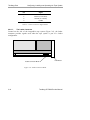
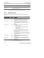
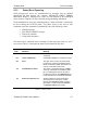
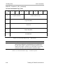
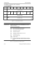
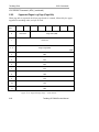
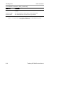
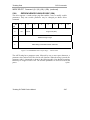
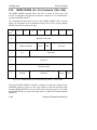
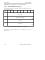
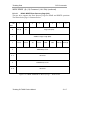
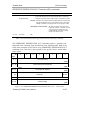
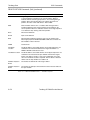
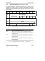
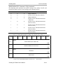
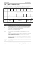
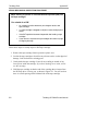
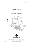
6HWWLQJWKH6&6,,'
Select the appropriate SCSI ID (IDs 0 through 15 are available) for the tape system
by installing jumper blocks on the pin pairs of the connector block located on the
tape system’s PCBA (Figure 2-1). Refer to Table 2-1 for the allowable SCSI IDs.
Front Bezel
SCSI ID Connector Block
A jumper must always be placed across Pin Pair 9 / 10 if
any SCSI ID other than the default (5) is selected.
Pin Pair 1 / 2
)LJXUH±/RFDWLRQRI6&6,,'&RQQHFWRU%ORFN
7DQGEHUJ'/73URGXFW0DQXDO
7DQGEHUJ'DWD
&RQILJXULQJ,QVWDOOLQJDQG2SHUDWLQJWKH7DSH6\VWHP
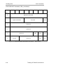
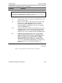
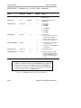
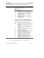
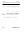
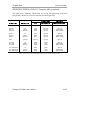
127(6
The default setting (no jumpers installed) for the tape system is SCSI ID
5. A jumper must DOZD\V be placed on pin pair (SCSI ID Present)
for the host to recognize DQ\ SCSI ID selections made on this connector,
otherwise, the SCSI ID remains SCSI ID 5.
Note that the SCSI ID of the host adapter is typically SCSI ID 7.
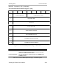
6&6,,'
0
3LQ3DLU
0
3LQ3DLU
0
3LQ3DLU
0
3LQ3DLU
0
1
0
0
0
1
2
0
0
1
0
3
0
0
1
1
4
0
1
0
0
5*
0
1
0
1
6
0
1
1
0
7
0
1
1
1
8
1
0
0
0
9
1
0
0
1
10
1
0
1
0
11
1
0
1
1
12
1
1
0
0
13
1
1
0
1
14
1
1
1
0
15
1
1
1
1
* = Default SCSI ID setting is SCSI ID 5.
0 = No jumper block installed on pin pair
1 = Jumper block installed on pin pair
7DEOH±6&6,,'-XPSHU6HWWLQJV
7DQGEHUJ'/73URGXFW0DQXDO
7DQGEHUJ'DWD
&RQILJXULQJ,QVWDOOLQJDQG2SHUDWLQJWKH7DSH6\VWHP
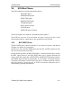
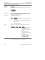
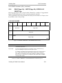
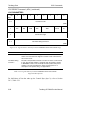
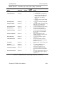
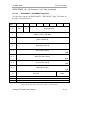
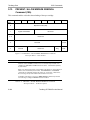
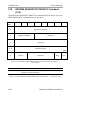
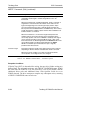
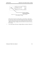
6HWWLQJ7(503:5
A SCSI bus must be terminated at each end of the bus. At least one device on the
bus must supply terminator power (TERM PWR).
To configure the DLT8000 tape drive to supply TERM PWR, install a jumper
block on pin pair (Figure 2-2).
Side View of Tape System
Front Bezel
Jumper on Pin Pair 3 / 4 enables
termination power (TERM PWR).
)LJXUH±-XPSHU,QVWDOOHGRQ3LQ3DLU
(QDEOHV7HUPLQDWLRQ3RZHU7(503:5
7DQGEHUJ'/73URGXFW0DQXDO
7DQGEHUJ'DWD
&RQILJXULQJ,QVWDOOLQJDQG2SHUDWLQJWKH7DSH6\VWHP
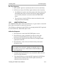
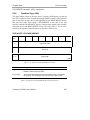
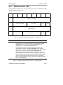
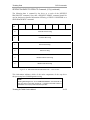
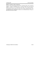
6HWWLQJ3DULW\&KHFNLQJ
Parity checking is the default setting for DLT8000 tape systems. If the system to
which you are configuring the tape system does not generate parity, disable parity
checking on the tape system by installing a jumper block on pin pair 1 / 2 on the
connector as shown in Figure 2-3. Note that this is the same connector as the one
used to select the setting for TERM PWR (Section 2.2.2).
Side View of Tape System
Front Bezel
Jumper on Pin Pair 1 / 2
disables parity checking.
)LJXUH±-XPSHU,QVWDOOHGRQ3LQ3DLU
'LVDEOHV3DULW\&KHFNLQJ
7DQGEHUJ'/73URGXFW0DQXDO
7DQGEHUJ'DWD
&RQILJXULQJ,QVWDOOLQJDQG2SHUDWLQJWKH7DSH6\VWHP
,QVWDOOLQJWKH7DSH6\VWHP
Installing the tape system requires securing the tape system in its bay or chassis
and connecting SCSI bus and power cables.
6HFXULQJWKH7DSH6\VWHPLQ%D\RU&KDVVLV
Using four (4) screws, secure the tape system in its bay or chassis.
Figure 2-4 is a dimensional drawing that shows the locations of the mounting holes
at the bottom and sides of the tape system.
Note that screws used to mount the tape system must be #6-32 UNC-2B screws.
When the recommended size screws are used, there is no danger of the screws
touching electronic components or otherwise damaging the tape system.
)LJXUH±/RFDWLRQVDQG'LPHQVLRQVIRU0RXQWLQJ+ROHV
7DQGEHUJ'/73URGXFW0DQXDO
7DQGEHUJ'DWD
&RQILJXULQJ,QVWDOOLQJDQG2SHUDWLQJWKH7DSH6\VWHP
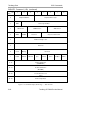
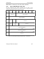
&RQQHFWLQJ6&6,%XVDQG3RZHU&DEOHV
Carefully connect the appropriate SCSI and power cables to their matching
connectors.
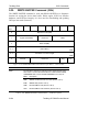
Figure 2-5 shows the location of the SCSI and power connectors on the rear of the
tape system. Tables 2-2 through 2-4 provide SCSI pin signal names/locations for
the SCSI connectors. Table 2-5 provides power connector signal names/locations.
127(
In some installations, it may be easier to connect the SCSI bus and power
cables before securing the tape system in its bay or position within its
cabinet or chassis.
Pin 1
68-Pin SCSI Connector
Pin 1
Power Connector
5HDU9LHZ&RQQHFWRU(QGRI7DSH6\VWHP
)LJXUH±&RQQHFWRUVIRU6&6,%XV&DEOHDQG3RZHU&DEOH
7DQGEHUJ'/73URGXFW0DQXDO
7DQGEHUJ'DWD
&RQILJXULQJ,QVWDOOLQJDQG2SHUDWLQJWKH7DSH6\VWHP
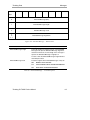
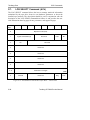
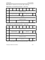
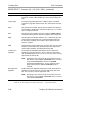
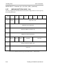
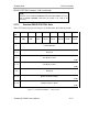
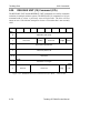
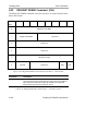
6LJQDO1DPH
3LQ1XPEHU
3LQ1XPEHU
6LJQDO1DPH
Signal Return
Signal Return
Signal Return
Signal Return
Signal Return
Signal Return
Signal Return
Signal Return
Signal Return
Signal Return
Signal Return
Signal Return
Signal Return
Signal Return
Signal Return
1
2
3
4
5
6
7
8
9
10
11
12
13
14
15
16
17
18
19
20
21
22
23
24
25
26
27
28
29
30
31
32
33
34
35
36
37
38
39
40
41
42
43
44
45
46
47
48
49
50
51
52
53
54
55
56
57
58
59
60
61
62
63
64
65
66
67
68
-DB(12)
-DB(13)
-DB(14)
-DB(15)
-DB(P1)
-DB(0)
-DB(1)
-DB(2)
-DB(3)
-DB(4)
-DB(5)
-DB(6)
-DB(7)
-DB(P0)
Ground
Ground
TERMPWR
TERMPWR
Reserved
Ground
-ATN
Ground
-BSY
-ACK
-RST
-MSG
-SEL
-C/D
-REQ
-I/O
-DB(8)
-DB(9)
-DB(10)
-DB(11)
Ground (DIFFSENS)
TERMPWR
TERMPWR
Reserved
Ground
Signal Return
Ground
Signal Return
Signal Return
Signal Return
Signal Return
Signal Return
Signal Return
Signal Return
Signal Return
Signal Return
Signal Return
Signal Return
Signal Return
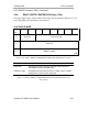
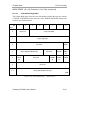
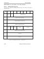
Note: The minus sign (-) next to a signal indicates active low.
7DEOH±3LQ6LQJOH(QGHG&RQILJXUDWLRQ6&6,&RQQHFWRU6LJQDO1DPHV
7DQGEHUJ'/73URGXFW0DQXDO
7DQGEHUJ'DWD
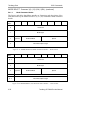
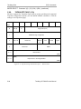
6LJQDO1DPH
+DB(12)
+DB(13)
+DB(14)
+DB(15)
+DB(P1)
+DB(0)
+DB(1)
+DB(2)
+DB(3)
+DB(4)
+DB(5)
+DB(6)
+DB(7)
+DB(P)
GROUND
DIFFSENS
TERMPWR
TERMPWR
RESERVED
GROUND
+ATN
GROUND
+BSY
+ACK
+RST
+MSG
+SEL
+C/D
+REQ
+I/O
+DB(8)
+DB(9)
+DB(10)
+DB(11)
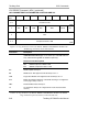
&RQILJXULQJ,QVWDOOLQJDQG2SHUDWLQJWKH7DSH6\VWHP
3LQ1XPEHU
1
2
3
4
5
6
7
8
9
10
11
12
13
14
15
16
17
18
19
20
21
22
23
24
25
26
27
28
29
30
31
32
33
34
3LQ1XPEHU
35
36
37
38
39
40
41
42
43
44
45
46
47
48
49
50
51
52
53
54
55
56
57
58
59
60
61
62
63
64
65
66
67
68
6LJQDO1DPH
-DB(12)
-DB(13)
-DB(14)
-DB(15)
-DB(P1)
-DB(0)
-DB(1)
-DB(2)
-DB(3)
-DB(4)
-DB(5)
-DB(6)
-DB(7)
-DB(P)
GROUND
GROUND
TERMPWR
TERMPWR
RESERVED
GROUND
-ATN
GROUND
-BSY
-ACK
-RST
-MSG
-SEL
-C/D
-REQ
-I/O
-DB(8)
-DB(9)
-DB(10)
-DB(11)
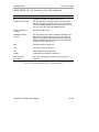
7DEOH±3LQ:LGH/9'9HUVLRQ6&6,&RQQHFWRU6LJQDO1DPHV
7DQGEHUJ'/73URGXFW0DQXDO
7DQGEHUJ'DWD
&RQILJXULQJ,QVWDOOLQJDQG2SHUDWLQJWKH7DSH6\VWHP
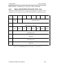
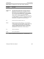
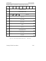
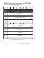
6LJQDO1DPH
3LQ1XPEHU
3LQ1XPEHU
6LJQDO1DPH
+DB(12)
+DB(13)
+DB(14)
+DB(15)
+DB(P1)
Ground
+DB(0)
+DB(1)
+DB(2)
+DB(3)
+DB(4)
+DB(5)
+DB(6)
+DB(7)
+DB(P)
DIFFSENS
TERMPWR
TERMPWR
Reserved
+ATN
Ground
+BSY
+ACK
+RST
+MSG
+SEL
+C/D
+REQ
+I/O
Ground
+DB(8)
+DB(9)
+DB(10)
+DB(11)
1
2
3
4
5
6
7
8
9
10
11
12
13
14
15
16
17
18
19
20
21
22
23
24
25
26
27
28
29
30
31
32
33
34
35
36
37
38
39
40
41
42
43
44
45
46
47
48
49
50
51
52
53
54
55
56
57
58
59
60
61
62
63
64
65
66
67
68
-DB(12)
-DB(13)
-DB(14)
-DB(15)
-DB(P1)
Ground
-DB(0)
-DB(1)
-DB(2)
-DB(3)
-DB(4)
-DB(5)
-DB(6)
-DB(7)
-DB(P)
Ground
TERMPWR
TERMPWR
Reserved
-ATN
Ground
-BSY
-ACK
-RST
-MSG
-SEL
-C/D
-REQ
-I/O
Ground
-DB(8)
-DB(9)
-DB(10)
-DB(11)
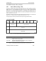
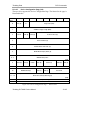
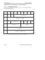
Note: The minus sign (-) next to a signal indicates active low.
7DEOH±3LQ'LIIHUHQWLDO9HUVLRQ6&6,&RQQHFWRU6LJQDO1DPHV
7DQGEHUJ'/73URGXFW0DQXDO
7DQGEHUJ'DWD
&RQILJXULQJ,QVWDOOLQJDQG2SHUDWLQJWKH7DSH6\VWHP
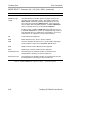
3LQ
6LJQDO
1
+12 VDC
2
Ground (+12 V return)
3
Ground (+5 V return)
4
+5 VDC
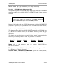
7DEOH±3RZHU&RQQHFWRU6LJQDO1DPHV
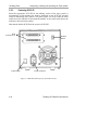
7KH/RDGHU&RQQHFWRU
Located on the side of the integratible tape system (Figure 2-6), the loader
connector provides signals used when the tape system is part of a loader
configuration.
Loader Connector Block
Front Bezel
)LJXUH±/RDGHU&RQQHFWRU%ORFN
7DQGEHUJ'/73URGXFW0DQXDO
7DQGEHUJ'DWD
&RQILJXULQJ,QVWDOOLQJDQG2SHUDWLQJWKH7DSH6\VWHP
&RQILJXULQJDQG,QVWDOOLQJD7DEOHWRS7DSH6\VWHP
This section provides instructions for configuring and installing the tabletop
version of the tape system. The tabletop version is enclosed in a top cover and the
enclosure includes a separate power supply. The power switch and the SCSI ID
selection switch are located on the unit’s rear panel. SCSI cables and the unit’s ac
power cable are connected at the rear panel.
:$51,1*
Before you begin, review the Safety, ESD, and Handling precautions
described at the beginning of this chapter to avoid personal injury or
damage to equipment.
This section contains information about configuring (“tailoring”) the tape system
via the unit’s external switches. Settings are included for the following options:
2SWLRQ
SCSI ID Selection
Connecting SCSI Cable(s) and/or Terminators
Connecting AC Power Cable
6HH6HFWLRQ«
2.3.1
2.3.2
2.3.3
127(
To disable parity, contact your service representative. There are no
external switches on the tabletop version to disable parity checking.
Figure 2-7 provides physical dimensions of the tabletop unit.
)LJXUH±3K\VLFDO'LPHQVLRQVRI'/77DEOHWRS6\VWHP
7DQGEHUJ'/73URGXFW0DQXDO
7DQGEHUJ'DWD
&RQILJXULQJ,QVWDOOLQJDQG2SHUDWLQJWKH7DSH6\VWHP
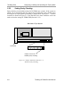
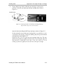
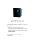
6HOHFWLQJ6&6,,'
Select the appropriate SCSI ID for the tabletop version of the tape system by
incrementing or decrementing the number displayed on the SCSI ID selection
switch on the tabletop tape system’s rear panel (Figure 2-8). Press either the small
switch above the indicator to increment the number, or the small switch below the
indicator to decrement the number.
Note that the default SCSI ID of the system is SCSI ID 3.
SCSI
Connectors (2)
SCSI ID
Switch
Fan
Power Switch
Power Connector
)LJXUH±'/77DEOHWRS7DSH6\VWHP5HDU3DQHO
7DQGEHUJ'/73URGXFW0DQXDO
7DQGEHUJ'DWD
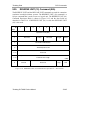
&RQILJXULQJ,QVWDOOLQJDQG2SHUDWLQJWKH7DSH6\VWHP
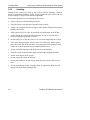
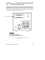
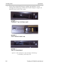
&RQQHFWLQJWKH6&6,%XV&DEOHV
Figure 2-9 shows the locations of the two SCSI bus connectors on the rear panel of
the tabletop tape system. The SCSI bus cable leading from the host adapter can be
connected to either of the connectors. If the tape unit is the last device on the bus,
then a terminator should be installed on the open connector. If the bus continues
from the tape system to another SCSI device, then install a SCSI bus cable between
the open connector and the next device on the bus.
SCSI Connectors (2)
7HUPLQDWRUV
3LQ/9'6(7HUPLQDWRU
3LQ+9''LIIHUHQWLDO7HUPLQDWRU
)LJXUH±/RFDWLRQRI6&6,%XV&RQQHFWRUVRQ5HDU3DQHO
7DEOHWRS9HUVLRQ
7DQGEHUJ'/73URGXFW0DQXDO
7DQGEHUJ'DWD
&RQILJXULQJ,QVWDOOLQJDQG2SHUDWLQJWKH7DSH6\VWHP
,QVWDOOLQJWKH$&3RZHU&RUG
:$51,1*
Do not attempt to modify or use an external 100 - 115 VAC power cord for
220 - 240 VAC input power. Modifying the power cord in any way can
cause personal injury and severe equipment damage.
An ac power cord is supplied with each tabletop tape unit. Carefully inspect the
power cord and ensure that the cord is the appropriate cord for your country or
region based on the criteria below.
The ac power cord used with the tabletop tape unit must meet the following
criteria:
1. The power cord should be a minimum of 18/3 AWG, 60°C, Type SJT or SVT.
2. UL and CSA Certified cordage rated for use at 250 VAC with a current rating
that is at least 125% of the current rating of the product.
3. The ac plug must be terminated in a grounding-type male plug designed for use
in your country or region. It must also have marks showing certification by an
agency acceptable in your country or region.
4. The connector at the tabletop unit end of the cord must be an IEC type CEE-22
female connector.
5. The cord must be no longer than 14.5 feet (4.5 meters).
Figure 2-10 shows different ac power cord plug-end configurations for 115 V and
220 / 240 V usage.
Note that the power supply of the tabletop unit has an auto-sensing feature; no
adjustment or switch setting changes are required for different ac sources.
7DQGEHUJ'/73URGXFW0DQXDO
7DQGEHUJ'DWD
&RQILJXULQJ,QVWDOOLQJDQG2SHUDWLQJWKH7DSH6\VWHP
115V
220V / 240V
)LJXUH±$&3RZHU&RUG3OXJ(QGV
7DQGEHUJ'/73URGXFW0DQXDO
7DQGEHUJ'DWD
&RQILJXULQJ,QVWDOOLQJDQG2SHUDWLQJWKH7DSH6\VWHP
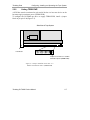
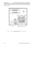
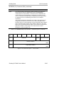
Figure 2-11 shows the location of the ac power cord connector on the tabletop tape
system’s rear panel.
AC Power Cord Connector
)LJXUH±/RFDWLRQRI$&3RZHU&RUG&RQQHFWRURQ5HDU3DQHO
7DEOHWRS9HUVLRQ
7DQGEHUJ'/73URGXFW0DQXDO
7DQGEHUJ'DWD
&RQILJXULQJ,QVWDOOLQJDQG2SHUDWLQJWKH7DSH6\VWHP
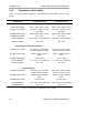
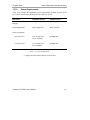
7KH7DSH&DUWULGJH
The tape system can use one of the following types of DLTtape cartridge:
7\SH
3ODVWLF&RORU
)HHW&DUWULGJH
DLTtape III
Greyish Brown
1200
DLTtape IIIXT
White
1800
DLTtape IV
Black
1800
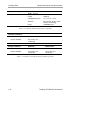
This section of the manual covers handling and care of tape cartridges, discusses
the tape cartridge write-protect switch, and explains how to load and unload a tape
cartridge to and from the tape system, and how to use a cleaning tape cartridge
7RSLF
6HH6HFWLRQ«
Care and Handling of Tape Cartridges
2.4.1
Tape Cartridge Write-Protect Switch
2.4.2
Loading a Tape Cartridge
2.4.3
Unloading a Tape Cartridge
2.4.4
How to Use a Cleaning Tape Cartridge
2.4.5
7DEOH±7DSH&DUWULGJH7RSLFV'LVFXVVHGLQWKLV0DQXDO
7DQGEHUJ'/73URGXFW0DQXDO
7DQGEHUJ'DWD
&RQILJXULQJ,QVWDOOLQJDQG2SHUDWLQJWKH7DSH6\VWHP
&DUHDQG+DQGOLQJRI7DSH&DUWULGJHV
Although designed and manufactured to withstand much handling and use, tape
cartridges should be handled properly.
•
Do not carry cartridges loosely in a box or other container that exposes them to
unnecessary physical shock.
•
Store each cartridge vertically in its protective case until needed.
•
Do not drop or bump the cartridge; this may dislodge and/or damage internal
components.
•
Avoid unnecessary opening of the cartridge door; this may expose the tape to
contamination or physical damage.
•
Do not allow direct contact with tape medium or the tape leader. Dust or
natural skin oils can contaminate the tape and impact performance.
•
Do not expose the cartridge to moisture or direct sunlight, dampness, or
condensation.
•
Maintain clean operating, working, and storage environments.
•
Do not place cartridges on or near devices that may produce magnetic fields
such as computer monitors, motors, or video equipment. Such exposure may
alter or erase data on the tape.
•
Do not attempt to remove a tape cartridge from the tape system unless the
Operate Handle indicator is illuminated steadily. Overriding the system handle
will cause damage to both the media and the tape system.
7DQGEHUJ'/73URGXFW0DQXDO
7DQGEHUJ'DWD
•
&RQILJXULQJ,QVWDOOLQJDQG2SHUDWLQJWKH7DSH6\VWHP
The ambient operating environment for the tape cartridge is
Temperature
10°C to 40°C (50°F to 104°F)
Relative Humidity
20% to 80% (non-condensing)
If storage and/or transportation of a tape cartridge has exposed it to conditions
outside the ambient values above, you should “condition” the tape cartridge to
its operating environment for a 24-hour period.
•
Place labels only in the front slide slot of the cartridge. Do not put any label on
the top, bottom, sides, or rear of the cartridge. This may interfere with normal
cartridge operation and may damage other subsystem components.
•
Do not use graphite pencils, water-soluble felt pens, or other debris-producing
writing instruments on your labels. Never erase a label – replace it.
•
Make sure you place the unused cartridge labels in the protective box so that
you do not inadvertently pick them up along with the cartridge during
subsequent usage. A static electricity charge on a cartridge may cause a label
to cling to the cartridge. A label that is accidentally inserted into the system
along with a cartridge can prevent the hub reel and system gear from meshing.
•
Follow all instructions for tape cartridge handling that accompany your
cartridges or tape system.
7DQGEHUJ'/73URGXFW0DQXDO
7DQGEHUJ'DWD
&RQILJXULQJ,QVWDOOLQJDQG2SHUDWLQJWKH7DSH6\VWHP
7DSH&DUWULGJH:ULWH3URWHFW6ZLWFK
7DSH&DUWULGJH/DEHO(QG
Write-Protect Switch pushed to the
ULJKW (Write Protect disabled position)
Orange Rectangle
Write-Protect Switch pushed to the
OHIW (Write Protect enabled position)
)LJXUH:ULWH3URWHFW6ZLWFKRQ7DSH&DUWULGJH
Each tape cartridge has a write-protect switch that can be used to prevent
accidental erasure of data. Before inserting the tape cartridge into the tape system,
position the write-protect switch on the front of the cartridge:
•
Move the write-protect switch to the left to HQDEOH write protection (existing
data on the tape cannot be overwritten, nor can additional data be appended to
the media).
When the write-protect switch is moved to the left, a small orange rectangle is
visible. This indicates that data cannot be written to the tape.
•
Move the write-protect switch to the right to GLVDEOH write protection (existing
data on the tape can be overwritten, and/or additional data can be appended to
the media unless the cartridge is write-protected via software). When writeprotect is disabled, no orange rectangle is visible.
7DQGEHUJ'/73URGXFW0DQXDO
7DQGEHUJ'DWD
&RQILJXULQJ,QVWDOOLQJDQG2SHUDWLQJWKH7DSH6\VWHP
When a tape cartridge is loaded in the system and the tape cartridge’s writeprotect switch is moved to its write-protected position (to the left as you face the
label/switch side of the tape cartridge), the system turns on its Write Protect
indicator immediately. If the system is currently writing to the tape, the writeprotect feature does not take effect until after the current WRITE operation
completes.
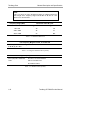
Table 2-7 describes the impact of moving the write-protect switch to its enabled
position before loading the cartridge; Table 2-8 describes the impact of doing so
when the switch is moved during a WRITE operation.
,IWKHZULWHSURWHFWVZLWFKLVPRYHG«
7KHQ«
To its left (enabled) position, the orange
indicator on the cartridge becomes visible
Data cannot be written to the tape.
To its right (disabled position), the orange
indicator is not visible
Data can be written to the tape (unless
software write-protect is in effect).
7DEOH±(QDEOLQJ:ULWH3URWHFW%HIRUH/RDGLQJWKH&DUWULGJH
,IWKHZULWHSURWHFWVZLWFKLVPRYHG«
7KHQ«
From its left (enabled) position to its right
(disabled, or write-enabled) position (orange
indicator is no longer visible)
The tape becomes write-enabled
AFTER a variable amount of seconds.
From its right (disabled, or write-enabled)
position to its left (enabled) position (orange
indicator becomes visible)
The tape becomes write-protected
AFTER a variable amount of seconds
(and once any current WRITE
operation is completed).
7DEOH±(QDEOLQJ:ULWH3URWHFW$IWHU/RDGLQJWKH&DUWULGJHDQG'XULQJ2SHUDWLRQ
7DQGEHUJ'/73URGXFW0DQXDO
7DQGEHUJ'DWD
&RQILJXULQJ,QVWDOOLQJDQG2SHUDWLQJWKH7DSH6\VWHP
&KHFNLQJD7DSH&DUWULGJH
Before you insert any tape cartridge, you should inspect it to ensure that it is not
damaged.
Refer to Appendix F for a detailed visual mechanical inspection procedure and
other DLTtape cartridge-related information.
•
Open the tape cartridge door and check the position of the tape leader.
•
Close the tape cartridge door and shake the cartridge, listening for a rattle
sound.
&$87,21
If the tape leader is missing or incorrectly positioned or if you hear a
rattling sound, the cartridge may be damaged. Inserting a damaged
cartridge into a tape system will damage the system. Discard any
damaged tape cartridges.
7DQGEHUJ'/73URGXFW0DQXDO
7DQGEHUJ'DWD
&RQILJXULQJ,QVWDOOLQJDQG2SHUDWLQJWKH7DSH6\VWHP
/RDGLQJD&DUWULGJH
127(
Because this section of the manual includes descriptions of the states of
indicators on the tape system, it may be useful to review sections of this
chapter that describe tape system indicators, their states, and meanings
of states.
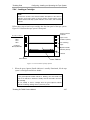
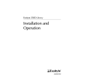
Follow these steps to load a tape cartridge into the front panel of the tape system.
Figure 2-13 illustrates the tape system’s front panel.
Write Protected
Indicator
Six Yellow Indicators
10.0 / 15.0
20.0
35.0
40.0
Tape In Use
Indicator (Yellow)
Use Cleaning
Tape
Compress
Density Override
Operate Handle
Indicator (Green)
Unload
Select Button
Insert / Release
)LJXUH±)URQW3DQHORI7DSH6\VWHP
1. When the green Operate Handle indicator is steadily illuminated, lift the tape
system’s cartridge Insert/Release handle.
127(
If the green Operate Handle indicator is blinking, close the handle and
wait for the indicator to illuminate steadily, then lift the handle and insert
the cartridge.
Do not attempt to load a cartridge when the green Operate Handle
indicator is blinking; damage to the system may result.
7DQGEHUJ'/73URGXFW0DQXDO
7DQGEHUJ'DWD
&RQILJXULQJ,QVWDOOLQJDQG2SHUDWLQJWKH7DSH6\VWHP
2. Insert the cartridge. Push the cartridge fully into the tape system.
&$87,21
To prevent failures and/or damage to the handle, assist the handle to its
closed position. Do not flip it or otherwise treat it roughly. Do not leave
your fingers under the handle: doing so may cause you to operate the
handle in an incorrect manner.
3. Push the handle to its closed (down) position.
The green Operate Handle indictor extinguishes and the yellow Tape in Use
indicator blinks to show that the tape is loading. When the tape reaches the BOT
marker, following calibration, the yellow indicator illuminates steadily. The tape is
now ready for use.
7DQGEHUJ'/73URGXFW0DQXDO
7DQGEHUJ'DWD
&RQILJXULQJ,QVWDOOLQJDQG2SHUDWLQJWKH7DSH6\VWHP
8QORDGLQJD&DUWULGJH
127(
Because this section of the manual includes descriptions of the states of
indicators on the tape system, it may be useful to review sections of this
chapter that describe tape system indicators, their states, and meanings
of states.
Follow the steps below the first &$87,21 notice to unload a tape cartridge.
&$87,21
Always remove the tape cartridge from the tape system BEFORE turning
off host power. Failure to remove a tape cartridge may result in cartridge
and/or tape system damage.
When you remove a tape cartridge from the system, return the cartridge
to its plastic case to protect the cartridge from damage.
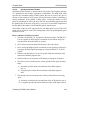
1. Press the Unload button (or issue an appropriate system software command).
The yellow Tape in Use indicator blinks as the tape rewinds.
&$87,21
Do NOT rush removal of the tape cartridge: premature removal can
cause tape leader failure. Wait until the Operate Handle indicator
illuminates a steady green. Delay removing the tape cartridge for one or
two seconds to ensure that the tape leader of the cartridge is in a safe
position for cartridge removal.
2. When the green Operate Handle indicator illuminates steadily, lift the tape
system cartridge Insert/Release handle to its open position to eject the
cartridge.
3. Remove the cartridge.
4. Push the Insert/Release handle to its closed position.
7DQGEHUJ'/73URGXFW0DQXDO
7DQGEHUJ'DWD
&RQILJXULQJ,QVWDOOLQJDQG2SHUDWLQJWKH7DSH6\VWHP
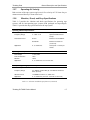
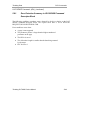
+RZDQG:KHQWR8VHD&OHDQLQJ7DSH&DUWULGJH
127(
Because this section of the manual includes descriptions of the states of
indicators on the tape system, it may be useful to review sections of this
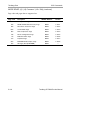
chapter that describe tape system indicators, their states, and meanings
of states.
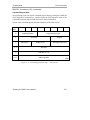
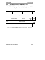
Use Table 2-9 to determine when to use a cleaning tape cartridge.
,I
,WPHDQV
$QG\RXVKRXOG«
The Use Cleaning Tape
indicator is steadily
illuminated
The recording head
needs cleaning or the
tape is bad.
Use the cleaning cartridge.
Follow the instructions in this
chapter for loading a cartridge
into the tape system. When
cleaning completes, the Use
Cleaning Tape indicator
extinguishes and the Operate
Handle indicator illuminates to
alert you that the cartridge can
be removed from the tape
system.
A data tape cartridge
causes Use Cleaning
Tape indicator to be
illuminated steadily
following the use of a
cleaning cartridge
The data cartridge may
be damaged.
If possible, back up the data
from this cartridge onto another
cartridge. Discard the damaged
cartridge: use of a damaged
cartridge may cause
unnecessary use of the cleaning
cartridge.
7DEOH±:KHQWR8VHD&OHDQLQJ&DUWULGJH
7DQGEHUJ'/73URGXFW0DQXDO
7DQGEHUJ'DWD
&RQILJXULQJ,QVWDOOLQJDQG2SHUDWLQJWKH7DSH6\VWHP
,I
,WPHDQV
$QG\RXVKRXOG«
The Use Cleaning Tape
indicator continues to be
illuminated steadily after you
have used a cleaning cartridge
to clean the recording head
Your cleaning tape
cartridge may be
exhausted.
Try another cleaning tape
cartridge.
The Use Cleaning Cartridge
indicator is illuminated steadily
while the tape system is in its
tape cleaning process
Cleaning of the system
had has not taken place;
the cartridge has
expired.*
Wait until the tape is
unloaded and the green
Operate Handle indicator
illuminates. Replace the
cleaning cartridge.
All indicators on the right-hand
side of the front bezel are
blinking
There may be a system
fault
Operate the handle to
remove the cartridge.
Inspect the tape cartridge. If
the cartridge appears
undamaged, it may be used
again, otherwise, take the
cartridge oout of service.
Reset the tape drive and
load a known good cartridge.
If all indicators on the righthand side of the bezel blink
again during the load, have
the tape drive serviced.
* A cleaning cartridge has a life expectancy of about 20 uses.
7DEOH±:KHQWR8VHD&OHDQLQJ&DUWULGJHFRQWLQXHG
7DQGEHUJ'/73URGXFW0DQXDO
7DQGEHUJ'DWD
&RQILJXULQJ,QVWDOOLQJDQG2SHUDWLQJWKH7DSH6\VWHP
2SHUDWLQJWKH7DSH6\VWHP±&RQWUROVDQG
,QGLFDWRUV
Operating the tape system requires use of a tape cartridge and the controls and
indicators on the front panel, or bezel, of the tape system.
All controls and indicators are located on the tape system’s front panel or bezel
(Figure 2-13). Use these controls and indicators to operate the tape system and
monitor the tape system’s activities.
See below for directions to which sections of this manual to use for explanations of
controls and indicators
&RQWURO,QGLFDWRU
6HH6HFWLRQ«
Unload Button (Figure 2-13)
Cartridge
Insert/Release
(Figure 2-13)
Selecting Density
2.5.1
Handle
2.5.2
2.5.3
7DQGEHUJ'/73URGXFW0DQXDO
7DQGEHUJ'DWD
&RQILJXULQJ,QVWDOOLQJDQG2SHUDWLQJWKH7DSH6\VWHP
8QORDG%XWWRQ
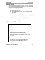
Use the Unload Button to unload the tape cartridge. When a user pushes the
Unload Button, the tape system waits until any active writing of data to tape is
completed, then begins its unload sequence.
The tape system rewinds the tape medium back into the cartridge and writes the
current or updated tape directory to the tape. The tape must be completely rewound
and unloaded into the cartridge before the cartridge can be removed from the tape
system. A complete unload operation may take 17 seconds from Beginning of Tape
(BOT).
Note that if the tape system is in an error state (all indicators on the right- or lefthand side of the front panel are flashing), pushing the Unload Button causes the
tape system to reset and unload the tape, if possible.
&DUWULGJH,QVHUW5HOHDVH+DQGOH
Use the Cartridge Insert/Release Handle to load or eject a tape cartridge only when
the tape system’s Operate Handle indicator is illuminated. Lift the handle to its
fully open position, or lower it to its fully closed position.
7DQGEHUJ'/73URGXFW0DQXDO
7DQGEHUJ'DWD
&RQILJXULQJ,QVWDOOLQJDQG2SHUDWLQJWKH7DSH6\VWHP
6HOHFWLQJ'HQVLW\
&$87,21
If the tape is not positioned at End of Data (EOD), a WRITE to the tape
will deny access to previously-recorded data beyond the current tape
position. To prevent this, position the tape to EOD, then perform the
WRITE. This condition is termed an “appended WRITE.”
127(6
TM
1. Default capacity of a DLTtape III cartridge is 10.0 GB, native or
20.0 GB (compression ON).
2.
Default capacity of a DLTtape IIIXT cartridge is 15.0 GB, native
(compression OFF), or 30.0 GB (compression ON).
3.
Default capacity of a DLTtape IV cartridge is 40.0 GB, native
(compression OFF), or 80 GB, compressed. A capacity of 35.0 GB
native (compression OFF, or 70 GB, compressed OR 20.0 GB native
(compression OFF), or 40 GB, compressed, is user-selectable.
Various storage capacities can be selected by specifying the GHQVLW\ of the data to
be recorded on the tape media.
Using the DLTtape IV cartridge:
1. On all READ and all WRITE APPEND operations, the data density that
already exists on the tape cartridge remains the density.
2. When writing from BOT, tape density may be changed by:
•
Using the Density Select Button on the front panel of the tape system.
8VLQJWKHIURQWSDQHO¶V'HQVLW\6HOHFW%XWWRQDOZD\VRYHUULGHVGHQVLW\
VHOHFWLRQYLDWKHKRVW
•
Using the operating system to issue a density designation. In this case, the
yellow Density Override indicator on the tape system’s front panel is
extinguished, indicating an automatic or host density selection.
Native default capacity for the DLTtape IV is 40.0 GB (80.0 GB, compressed),
assuming the Density Select Button was not used or that host selection of density
via the operating system was not invoked.
7DQGEHUJ'/73URGXFW0DQXDO
7DQGEHUJ'DWD
&RQILJXULQJ,QVWDOOLQJDQG2SHUDWLQJWKH7DSH6\VWHP
7RVHOHFWGHQVLW\RQWKHWDSHV\VWHP
Load the tape cartridge into the tape system. The yellow Tape in Use indicator
blinks while the tape loads and calibrates.
After calibration is compete, the Tape In Use indicator remains steadily
illuminated. The appropriate tape density indicator along the left edge of the
system’s front panel illuminates to indicate the tape’s prerecorded density (if any).
Use the tape system’s density Select Button to select the desired density, if
different than that indicated by the illuminated tape density indicator. Density
selection is inactive until a WRITE from BOT is issued. The controller retains the
selected density until 1) the density selection is changed, or 2) the tape is unloaded.
An example of selection of density follows.
(;$03/(
A user loads a tape cartridge previously recorded at 20.0 GB capacity.
The user then presses the Density Select Button to select the density for
40.0 GB capacity. The following events take place:
•
The yellow 20.0 indicator remains illuminated – the density has not
yet changed and the steadily illuminated indicator reflects the tape’s
recorded density.
•
The yellow 40.0 indicator blinks – this signals that a density change is
pending.
•
The yellow Density Override indicator illuminates.
When a WRITE from BOT occurs:
•
The yellow 20.0 indicator extinguishes
•
The yellow 40.0 indicator illuminates steadily
•
The yellow Density Override indicator remains illuminated
Table 2-10 explains the activity of indicators during density selection.
7DQGEHUJ'/73URGXFW0DQXDO
7DQGEHUJ'DWD
&RQILJXULQJ,QVWDOOLQJDQG2SHUDWLQJWKH7DSH6\VWHP
,I«
7KHQ«
The Density Select Button is not used
The illuminated indicators show data
density when the tape is being read
from and written to. The indicators
illuminate steadily; Density Override
remains extinguished.
The Density Select Button is used and the
actual recorded density is the same as the
density selected via the button
The indictor that reflects the actual data
density and the Density Override
indicators both are illuminated. For
example, if the actual data density is
set for 10.0 GB and 10.0 GB is selected
via the Select Button, the indicator next
to “10.0” illuminates.
The Density Select Button is used and the
actual recorded density differs from the density
selected via the button
1. The indicator that reflects the
actual data density illuminates
steadily.
2. The indicator reflected the
SELECTED density blinks.
3. The Density Override illuminates
steadily.
For example, if the actual tape data
density is set for 40.0 GB and the
selected density is 20.0 GB, the 40.0
indicator lights steadily, the 20.0
indicator blinks, and the Density
Override indicator illuminates steadily.
7DEOH±,QGLFDWRU/LJKW$FWLYLW\'XULQJ'HQVLW\6HOHFWLRQ
7RVHOHFWGHQVLW\YLDWKHKRVWRYHUWKH6&6,EXV
1. Use the SCSI MODE SELECT command to indicate the desired data density
(Chapter 5).
2. Write data to the tape from BOT.
7DQGEHUJ'/73URGXFW0DQXDO
7DQGEHUJ'DWD
&RQILJXULQJ,QVWDOOLQJDQG2SHUDWLQJWKH7DSH6\VWHP
3RZHU2Q6HOI7HVW3267DQG,QGLFDWRU
$FWLYLW\'XULQJ3267
When power is applied to the tape system, it performs power-on self testing
(POST). The sequence of events that may be observed is:
6WDJH
:KDW&DQEH2EVHUYHG
1
Indicators on the right-hand side of the front panel illuminate in
sequence from top to bottom. All indicators remain illuminated
for a few seconds.
2
The indicators along the left-hand side of the front panel
illuminate together for about three seconds, then extinguish.
3
The green Operate Handle, orange Write Protected, and yellow
User Cleaning Tape indicators extinguish. The yellow Tape in
Use indicator blinks while the tape system initializes.
4
Following initialization, the tape system is in one of the states
described in Table 2-12.
7DEOH±,QGLFDWRU$FWLYLW\'XULQJ3267
6WDWH
,QGLFDWRU'LVSOD\DQG$FWLYLW\
A tape cartridge is present and
the handle is down
The tape system loads the medium from the cartridge.
When the yellow Tape In Use indicator stops blinking
and remains illuminated. The indicator next to the
tape’s actual density is illuminated. When Density
Override blinks, a density may be selected. The tape
system is ready for use and the media is positioned at
BOT.
No tape cartridge present
Yellow Tape in Use indicator extinguishes.
Green Operate Handle indicator illuminates.
Insert/Release Handle is unlatched.
7DEOH±3RVVLEOH7DSH6\VWHP6WDWHV)ROORZLQJ,QLWLDOL]DWLRQ
7DQGEHUJ'/73URGXFW0DQXDO
7DQGEHUJ'DWD
&RQILJXULQJ,QVWDOOLQJDQG2SHUDWLQJWKH7DSH6\VWHP
6WDWH
,QGLFDWRU'LVSOD\DQG$FWLYLW\
A tape cartridge is present, but
the handle is up (not
recommended)
The yellow Tape In Use indicator extinguishes. The
green Operate Handle indicator flashes. When the
Insert/Release Handle is lowered, the cartridge loads. If
handle will not lower, ensure the tape cartridge is
pushed all the way into the tape system.
The tape system detects an
error condition
Right- or left-hand indicators blink repeatedly. Try to
unload the tape and reinitialize the tape system by
pressing the Unload button, or turn system power off
then back on. The indicators stop blinking and the
system attempts reinitialization. Note that after pressing
the Unload button you may have to wait five minutes
before the Operate Handle indicator illuminates due to
the retry being attempted first. The indicators illuminate
steadily, then extinguish if the test succeeds.
The system is powered on with
the handle in open position
Operate Handle indicator is blinking. Close the
Insert/Release Handle and wait for indicator to
illuminate steadily.
7DEOH±3RVVLEOH7DSH6\VWHP6WDWHV)ROORZLQJ,QLWLDOL]DWLRQFRQWLQXHG
POST completes in about 15 seconds and the tape system should respond normally
to all commands (POST is complete after Stage 2 in Table 2-11). However, it
might take longer for the media to become ready.
After a bus reset, the tape system responds within a bus selection time-out period
(per the ANSI SCSI specification). A reset may have the Tape In Use indicator
blinking because a reset forces the tape to be rewound to BOT.
7DQGEHUJ'/73URGXFW0DQXDO
7DQGEHUJ'DWD
&RQILJXULQJ,QVWDOOLQJDQG2SHUDWLQJWKH7DSH6\VWHP
7DSH6\VWHP2SHUDWLQJ0RGHVDQG,QGLFDWRU
$FWLYLW\
Table 2-13 describes the various operating conditions of a tape system and what
observations can be made of the various indicators for each mode. A detailed
description of the modes for the Tape in Use indicator is provided.
)URQW3DQHO
,QGLFDWRU
Write Protected
&RORURI,QGLFDWRU
Orange
Tape in Use
Yellow
Use Cleaning Tape
Yellow
6WDWH
On
Off
Blinking
On
Off
On
Remains on after
cleaning tape unloads
After cleaning,
indicator illuminates
again when (data)
tape cartridge is
reloaded.
Off
Operate Handle
Green
On
Off
Blinking
2SHUDWLQJ0RGH
Tape is WriteProtected
Tape is Write-Enabled
Tape is moving
Tape is loaded; ready
for use.
Tape not loaded
Tape system needs
cleaning or tape is
bad.
Cleaning tape
attempted to clean the
system head, but the
tape expired so
cleaning was not
done.
Problem tape
cartridge. Try another
cartridge. If problem
indication persists,
contact service
representative.
Cleaning is complete
or cleaning is
unnecessary.
Insert/Release handle
can be operated.
Do not operate
Insert/Release handle.
Close the
Insert/Release handle
and wait for Operate
Handle indicator to
illuminate steadily
7DEOH±7DSH6\VWHP2SHUDWLQJ0RGHV,QGLFDWRU$FWLYLW\
7DQGEHUJ'/73URGXFW0DQXDO
7DQGEHUJ'DWD
)URQW3DQHO
,QGLFDWRU
All four right-hand
or all six left-hand
indicators
10.0 / 15.0
20.0
&RQILJXULQJ,QVWDOOLQJDQG2SHUDWLQJWKH7DSH6\VWHP
&RORURI
,QGLFDWRU
---
Yellow
Yellow
35.0
Yellow
40.0
Yellow
Compress
Yellow
6WDWH
On
Blinking
2SHUDWLQJ0RGH
POST is beginning
An error has occurred. See Section
2.9 for troubleshooting.
On
Blinking
Tape is recorded in 10.0 / 15.0 GB
format
Tape is recorded in another density,
10.0 / 15.0 GB has been selected for
a WRITE from BOT.
On
Tape is recorded in 20.0 GB format
Blinking
Tape is recorded in another density;
20.0 GB has been selected for a
WRITE from BOT.
On
Tape is recorded in 35.0 GB format
Blinking
Tape is recorded in another density;
35.0 GB has been selected for a
WRITE from BOT.
On
Tape is recorded in 40.0 GB format
Blinking
Tape is recorded in another density,
40.0 GB has been selected for a
WRITE from BOT.
On
Compression mode enabled
(compression only valid for 10, 15,
20, or 35 GB densities only)
Compression mode disabled
Off
Density Override
Yellow
On
Off
Operator selected a density from the
density Select Button on the front
panel and/or compression
Density to be selected by the host
(automatic)
7DEOH±7DSH6\VWHP2SHUDWLQJ0RGHV,QGLFDWRU$FWLYLW\FRQWLQXHG
7DQGEHUJ'/73URGXFW0DQXDO
7DQGEHUJ'DWD
&RQILJXULQJ,QVWDOOLQJDQG2SHUDWLQJWKH7DSH6\VWHP
7DSHLQ8VH,QGLFDWRUDQG0RGHV
Whenever the yellow Tape in Use indicator is illuminated steadily, the tape system
and cartridge are ready to use. When the system is calibrating, reading, writing, or
rewinding the tape, the Tape in Use indicator blinks.
Table 2-14 explains each of the modes of the Tape in Use Indicator.
,IWKH\HOORZ7DSHLQ8VH,QGLFDWRULV«
,WPHDQV«
Illuminated, steadily
A cartridge is loaded in the tape system, but
the tape is not moving. This may mean no
application is communicating with the tape
system’s controller, or that the application is
communicating but is not delivering any
command that impact tape motion.
Blinking irregularly
A calibration, read, or write operation is in
progress.
Blinking regularly
The tape is loading, unloading, or rewinding.
Off
No tape loaded in tape system.
7DEOH±7DSHLQ8VH,QGLFDWRU0RGHV
7DQGEHUJ'/73URGXFW0DQXDO
7DQGEHUJ'DWD
&RQILJXULQJ,QVWDOOLQJDQG2SHUDWLQJWKH7DSH6\VWHP
8VLQJWKH'/77DSH6\VWHP¶V%DVLF+HDOWK
&KHFN%+&7HVW)HDWXUH
127(
The BHC feature is provided for use only by a trained service provider.
The BHC test uses the tape system’s firmware to check the various EEROM-based
information packets for log entries of events that have occurred in the previous 120
hours of operation. Based on that information, the system can report on its
“health.” The test is pass/fail only.
You can invoke the BHC test three ways: via the tape drive’s front panel, the
system’s library port, or via the SCSI SEND DIAGNOSTIC command. This guide
explains how to run the BHC test via the front panel; note that the BHC test cannot
be run if a SEND DIAGNOSTIC command is in progress or if the BHC Test is
already running.
5XQQLQJWKH%+&7HVW8VLQJWKH)URQW3DQHO
1.
Press and KROG the Density Select Button (Figure 13) for five seconds. The Density
Override Indicator (Figure 2-13) flashes for five seconds. After the five seconds, the
top two Density Indicators (Figure 2-13) will illuminate.
2.
Release, then momentarily hold the Density Select Button. The top two Density
Indicators will flash, indicating that the BHC test is running. The two Density
Indicators continue to flash while the test proceeds.
127(6
1. If the Density Select Button is pressed and held for fewer than five
seconds, the BHC test will not run and the Density Indicators return
to their original state.
2.
If the Density Select Button is not released then momentarily
pressed again, the BHC test will not run and the Density Indicators
return to their original state.
,IWKHWHVWSDVVHVWKHWRSIRXU'HQVLW\,QGLFDWRUVilluminate steadilyIRUILYHVHFRQGVWKHQ
UHWXUQWRWKHLURULJLQDOVWDWH
,IWKHWHVWIDLOVWKHWRSIRXU'HQVLW\,QGLFDWRUVflash on and offIRUILYHVHFRQGVWKHQUHWXUQ
WRWKHLURULJLQDOVWDWH
7DQGEHUJ'/73URGXFW0DQXDO
7DQGEHUJ'DWD
&RQILJXULQJ,QVWDOOLQJDQG2SHUDWLQJWKH7DSH6\VWHP
7URXEOHVKRRWLQJ
Use Table 2-15 for troubleshooting tips in the event that your tape system fails its
power-on self test or if it signals a problem via its front panel indicators.
,I«
7KHQ«
<RX6KRXOG«
System does not
recognize the tape
system
System may not be configured
to recognize the SCSI ID.
Configure system to recognize
the tape system’s ID
SCSI ID may not be unique
Change the SCSI ID and
reconfigure the system. The
new ID becomes effective at
the next power on or SCSI bus
reset.
SCSI adapter parameters may
not be correct
Check SCSI adapter
documentation
SCSI signal cable may be
loose
Ensure SCSI cable is fully
seated at each connector end
SCSI terminator may be loose
or not present on the bus
Ensure correct, secure
termination of bus.
SCSI bus may not be
terminated correctly
If tape system is last or only
device on bus (except for
adapter), make sure terminator
is installed on tape system.
If tape system is not the last or
only device on the bus, check
the cable connections and
ensure that the bus is properly
terminated at each end.
SCSI terminator may not be at
end of bus or more than two
terminators may be present
Ensure that a terminator is
installed at each end of the
bus. One terminator is usually
installed at the host end of the
bus.
7DEOH±7URXEOHVKRRWLQJ&KDUWFRQWLQXHG
7DQGEHUJ'/73URGXFW0DQXDO
7DQGEHUJ'DWD
&RQILJXULQJ,QVWDOOLQJDQG2SHUDWLQJWKH7DSH6\VWHP
,I«
7KHQ«
<RX6KRXOG«
System does not recognize the
tape system (continued)
1. SCSI bus may be too
1. Limit bus length to ANSI
long.
SCSI standard for the
SCSI interface being
used.
2. Too many devices on the
bus.
2. Limit the number of
devices on the bus
(including the SCSI
adapter) to match the
limits of the interface
being used.
The tape system does not
power up
No power is reaching the tape
system
Check the tape system’s
power cable connection at the
rear of the system.
All right-hand or left-hand
indicators on the tape system
front panel are blinking
A system fault has occurred
Try to unload the tape and
reinitialize the system by
pressing the Unload button, or
by turning power to the system
off then back on. The
indicators stop blinking as the
system attempts
reinitialization. The indicators
illuminate steadily again, then
extinguish if the test succeeds.
&$87,21
If this happens multiple times, contact your service
representative.
Nonfatal or fatal errors occur
for which the cause cannot be
determined
SCSI bus termination or the
SCSI bus cable connections
may be incorrect
Ensure the SCSI bus is
terminated and that all
connections are secure.
The ac power source
grounding may be incorrect
(tabletop version).
Use an ac outlet for the
tabletop tape unit on the same
ac line used by the host
system.
7DEOH±7URXEOHVKRRWLQJ&KDUWFRQWLQXHG
7DQGEHUJ'/73URGXFW0DQXDO
7DQGEHUJ'DWD
&RQILJXULQJ,QVWDOOLQJDQG2SHUDWLQJWKH7DSH6\VWHP
,I«
7KHQ«
<RX6KRXOG«
Indicators along right-hand
side of front panel are blinking
and the Operate Handle Light
is illuminated steadily
The tape leader may be
dropped.
Open the handle and look
inside the tape system. If the
tape leader is missing
contact your service
representative. Also, check
the tape cartridges for
damage.
7DEOH±7URXEOHVKRRWLQJ&KDUWFRQWLQXHG
If, after attempting the recommended actions listed in Table 2-14, the problem still
exists or returns, a hardware failure may be the cause. Contact a service
representative.
Refer to Appendix F for complete visual inspection instructions for DLTtape
cartridges.
The web site http://www.dlttape.com includes much valuable information about
DLTtape systems.
7DQGEHUJ'/73URGXFW0DQXDO
7DQGEHUJ'DWD
&RQILJXULQJ,QVWDOOLQJDQG2SHUDWLQJWKH7DSH6\VWHP
7KLV3DJH,QWHQWLRQDOO\/HIW%ODQN
7DQGEHUJ'/73URGXFW0DQXDO
6&6,'HVFULSWLRQ
7KLVFKDSWHUSURYLGHVDGHWDLOHGGHVFULSWLRQRIWKHORJLFDOLQWHUIDFHVRIWKHWDSHGULYH7KH
GULYHLVIXOO\FRPSOLDQWZLWKWKH$16,6&6,VWDQGDUGIRUWDSHGULYHGHYLFHVDQG
LPSOHPHQWVPDQ\RSWLRQDOIHDWXUHV
6&6,2YHUYLHZ
The Small Computer System Interface (SCSI) is a specification for a peripheral
bus and command set that is an ANSI standard. The standard defines an I/O bus
that supports up to 16 devices (wide SCSI).
ANSI defines three primary objectives of SCSI-2:
1. To provide host computers with device-independence within a class of
devices
2. To be backward-compatible with SCSI-1 devices that support bus
parity and that meet conformance level 2 of SCSI-1
3. To move device-dependent intelligence to the SCSI-2 devices
Important features of SCSI-2 implementation include the following:
•
•
•
•
•
•
•
Efficient peer-to-peer I/O bus with up to 16 devices
Asynchronous transfer rates that depend only on device
implementation and cable length
Logical addressing for all data blocks (rather than physical addressing)
Multiple initiators and multiple targets
Distributed arbitration (bus contention logic)
Command queuing
Command set enhancement
7DQGEHUJ'/73URGXFW0DQXDO
7DQGEHUJ'DWD
6&6,'HVFULSWLRQ
6&6,&RPPDQGV
ANSI classifies SCSI commands as mandatory, optional, or vendor-specific. The
mandatory and optional commands implemented for the drives are summarized in
Table 3–1 and described fully in Chapter 5, SCSI Commands.
&RPPDQG
&RGH
&ODVV
'HVFULSWLRQ
ERASE
19h
Mandatory
Causes part of all of the tape medium
to be erased, beginning at the current
position on the logical unit.
INQUIRY
12h
Mandatory
Requests that information about the
tape drive be sent to the initiator.
LOAD UNLOAD
1Bh
Optional
Causes tape to move from not ready to
ready. Prior to performing the load
unload, the target ensures that all data,
filemarks, and/or setmarks shall have
transferred to the tape medium.
LOCATE
2Bh
Optional
Causes the target to position the logical
unit to the specified block address in a
specified partition. When complete, the
logical position is before the specified
position.
LOG SELECT
4Ch
Optional
Provides a means for the initiator to
manage statistical information
maintained by the drive about the drive.
This standard defines the format of the
log pages but does not define the exact
conditions and events that are logged.
LOG SENSE
4Dh
Optional
Provides a means for the initiator to
retrieve statistical information
maintained by the drive about the drive.
7DEOH±,PSOHPHQWHG$16,6&6,&RPPDQGV
7DQGEHUJ'/73URGXFW0DQXDO
7DQGEHUJ'DWD
6&6,'HVFULSWLRQ
&RPPDQG
&RGH
&ODVV
'HVFULSWLRQ
MODE SELECT (6)
15h
Optional
Provides a means for the initiator to
specify device parameters.
MODE SENSE
(6)/(10)
1Ah/
5Ah
Optional
Provides a means for a drive to report
parameters to the initiator.
PREVENT ALLOW
MEDIUM REMOVAL
1Eh
Optional
Requests that the target enable or
disable the removal of the medium in
the logical unit. Medium cannot be
removed if any initiator has medium
removal prevented.
READ
08h
Mandatory
Requests the drive to transfer data to
the initiator.
READ BLOCK
LIMITS
05h
Mandatory
Requests that the logical unit’s block
length limits capability be returned
READ BUFFER
3Ch
Optional
Used in conjunction with the WRITE
BUFFER command as a diagnostic
function for testing target memory and
the integrity of the SCSI bus. This
command does not alter the medium.
READ POSITION
34 h
Optional
Reports the current position of the
logical unit and any data blocks in the
buffer.
RECEIVE DIAG
RESULTS
1Ch
Optional
RELEASE UNIT
17h
Mandatory
REQUEST SENSE
03h
Mandatory
Requests analysis data to be sent to
the initiator after completion of a SEND
DIAGNOSTIC Command.
Used to release a previously reserved
logical unit.
Requests the drive to
transfer sense data to
the initiator.
RESERVE UNIT
16h
Mandatory
Used to reserve a
logical unit.
SEND DIAGNOSTIC
1Dh
Mandatory
Requests the drive to perform diagnostic
operations on itself.
SPACE
11h
Mandatory
Provides a selection of positioning
functions (both forward and backward)
that are determined by the code and
count.
7DEOH±,PSOHPHQWHG$16,6&6,&RPPDQGFRQWLQXHG
7DQGEHUJ'/73URGXFW0DQXDO
7DQGEHUJ'DWD
6&6,'HVFULSWLRQ
&RPPDQG
&RGH
&ODVV
'HVFULSWLRQ
TEST UNIT READY
00h
Mandatory
Provides a means to check if the logical
unit is ready.
VERIFY
2Fh
Optional
Requests the drive to verify the data
written to the medium.
WRITE
0Ah
Mandatory
Requests the drive to write the data
transferred from the initiator to the
medium.
WRITE BUFFER
3Bh
Optional
Used in conjunction with the READ
BUFFER command as a diagnostic for
testing target memory and the integrity
of the SCSI bus.
WRITE FILEMARKS
10h
Mandatory
Requests that the target write the
specified number of filemarks or
setmarks to the current position on the
logical unit.
7DEOH±,PSOHPHQWHG$16,6&6,&RPPDQGFRQWLQXHG
7DQGEHUJ'/73URGXFW0DQXDO
7DQGEHUJ'DWD
6&6,'HVFULSWLRQ
6LJQDO6WDWHV
The following paragraphs describe signal values and SCSI ID bits.
6LJQDO9DOXHV
All signal values are actively driven true (low voltage). Because the signal drivers
are OR-tied, the bus terminator’s bias circuitry pulls false when it is released by
the drivers at every SCSI device. If any device asserts a signal, (e.g., OR-tied
signals), the signal is true. Table 3–2 shows the ANSI-specified and defined signal
sources. Any device can assert RST at any time.
6LJQDOV
'%±
'%
%XV3KDVH
%6<
6(/
06*5(4
&',2
$&.$71
'%3
'%3
BUS FREE
ARBITRATION
SELECTION
RESELECTION
COMMAND
DATA IN
DATA OUT
STATUS
MESSAGE IN
MESSAGE OUT
None
All
I&T
I&T
Targ
Targ
Targ
Targ
Targ
Targ
None
Winner
Init
Targ
None
None
None
None
None
None
None
None
None
Targ
Targ
Targ
Targ
Targ
Targ
Targ
None
None
Init
Init
Init
Init
Init
Init
Init
Init
None
S ID
Init
Targ
Init
Targ
Init
Targ
Targ
Init
None
S ID
Init
Targ
None
Targ
Init
None
None
None
All:
The signal is driven by all SCSI devices that are actively arbitrating.
SCSI ID: Each SCSI device that is actively arbitrating asserts its unique SCSI ID
bit. The other seven (or fifteen) data bits are released. The parity bit
(DB(P or P1) can be released or driven true, but is never driven false
during this phase.
I&T:
The signal is driven by the initiator, drive, or both, as specified in the
SELECTION and RESELECTION phase.
Init:
If driven, this signal is driven only by the active initiator.
None:
The signal is released; that is, not driven by any SCSI device. The bias
circuitry of the bus terminators pulls the signal to the false state.
Winner: The signal is driven by the winning SCSI device.
Targ:
If the signal is driven, it is driven only by the active drive.
7DEOH±6LJQDO6RXUFHV
7DQGEHUJ'/73URGXFW0DQXDO
7DQGEHUJ'DWD
6&6,'HVFULSWLRQ
6&6,,'%LWV
SCSI permits a maximum of eight SCSI devices on a SCSI bus (16 devices are
permitted when using wide SCSI). Each SCSI device has a unique SCSI ID
assigned to it. This SCSI ID provides an address for identifying the device on the
bus. On the drive, the SCSI ID is assigned by configuring jumpers or connecting
remote switches to the option connector. Chapter 2, +DUGZDUH,PSOHPHQWDWLRQ has
full instructions for setting the SCSI ID.
7DQGEHUJ'/73URGXFW0DQXDO
7DQGEHUJ'DWD
6&6,'HVFULSWLRQ
6&6,6LJQDOV
The following paragraphs define SCSI signals and bus timing values.
6&6,6LJQDO'HILQLWLRQV
Table 3–3 defines the SCSI bus signals.
6LJQDO
'HILQLWLRQ
ACK (acknowledge)
A signal driven by the initiator as an acknowledgment of receipt of
data from a target or as a signal to a target indicating when the
target should read the data (out) lines.
ATN (attention)
A signal driven by an initiator to indicate that it has a message to
send.
BSY (busy)
An OR-tied signal that indicates that the bus is in use.
C/D (control/data)
A signal driven by a target that indicates whether CONTROL or
DATA information is on the DATA BUS. True (low voltage)
indicates CONTROL.
DB(7–0,P) (data bus)
Eight data-bit signals, plus a parity-bit signal that form a DATA
BUS. DB(7) is the most significant bit and has the highest priority (8
or 16-bit) during ARBITRATION. Bit number, significance, and
priority decrease downward to DB(0). A data bit is defined as 1
when the signal value is true (low voltage) and 0 when the signal
value is false (high voltage). Data parity DB(P) is odd. Parity is
undefined during ARBITRATION.
DB(15–8,P1) (data bus)
Eight data-bit signals, plus one parity-bit signal, that forms an
extension to the DATA BUS. They are used for 16-bit (wide)
interfaces. DB(15) is the most significant bit and has the higher
priority (but below bit DB(0) during ARBITRATION. Bit number,
significance, and priority decrease downward to DB(8). Data Parity
DB (P1) is odd.
I/O (input/output)
A signal driven by a target that controls the direction of data
movement on the DATA BUS with respect to an initiator. True
indicates input to the initiator.
Also used to distinguish between SELECTION and RESELECTION
modes.
MSG (message)
A signal driven by a target during the MESSAGE phase.
REQ (request)
A signal driven by a target to indicate a request for an information
transfer to or from the initiator. Each byte of data transferred is
accompanied with a REQ/ACK “handshake”. See also, $&.
7DEOH±6&6,%XV6LJQDO'HILQLWLRQV
7DQGEHUJ'/73URGXFW0DQXDO
7DQGEHUJ'DWD
6&6,'HVFULSWLRQ
6LJQDO
'HILQLWLRQ
RST (reset)
An OR-tied signal that initiates a RESET condition.
SEL (select)
An OR-tied signal used by an initiator to select a target or by a
target to reselect an initiator.
7DEOH±6&6,%XV6LJQDO'HILQLWLRQVFRQWLQXHG
6LJQDO%XV7LPLQJ
The ANSI SCSI-2 standard defines the SCSI bus timing values shown in
Table 3–4.
7LPLQJ'HVFULSWLRQ
9DOXH
'HVFULSWLRQ
Arbitration Delay
2.4 µs
Minimum time a SCSI device waits from asserting BSY for
arbitration until the DATA BUS can be examined to see if
arbitration has been won; there is no maximum time.
Assertion Period
90 ns
Minimum time a drive asserts REQ while using
synchronous data transfers; also, the minimum time that an
initiator asserts ACK while using synchronous data
transfers.
Bus Clear Delay
800 ns
Maximum time for a SCSI device to stop driving all bus
signals after:
1. BUS FREE is detected.
2. SEL is received from another SCSI device during
ARBITRATION.
3. Transition of RST to true.
For condition 1, the maximum time for a SCSI device to
clear the bus is 1200 ns (1.2 µs) from BSY and SEL first
becoming both false.
If a SCSI device requires more than a bus settle delay to
detect BUS FREE, it clears the bus within a bus clear delay
minus the excess time.
Bus Free Delay
800 ns
Maximum time a SCSI device waits from its detection of
BUS FREE until its assertion of BSY when going to
ARBITRATION.
Bus Set Delay
1.8 µs
Maximum time for a device to assert BSY and its SCSI ID
bit on the DATA BUS after it detects BUS FREE to enter
ARBITRATION.
7DEOH±6&6,%XV7LPLQJ9DOXHV
7DQGEHUJ'/73URGXFW0DQXDO
7DQGEHUJ'DWD
6&6,'HVFULSWLRQ
7LPLQJ'HVFULSWLRQ
9DOXH
'HVFULSWLRQ
Bus Settle Delay
400 ns
Minimum time to wait for the bus to settle after changing
certain control signals as called out in the protocol
definitions
Cable Skew Delay
10 ns
Maximum difference in propagation time allowed between
any two SCSI bus signals measured between any two SCSI
devices.
Data Release Delay
400 ns
Maximum time for an initiator to release the DATA BUS
signals following the transition of the I/O signal from false to
true.
Deskew Delay
45 ns
Minimum time required to wait for all signals (especially
data signals) to stabilize at their correct, final value after
changing.
Disconnection Delay
200 µs
Minimum time that a drive waits after releasing BSY before
participating in an ARBITRATION when honoring a
DISCONNECT message from the initiator.
Hold Time
45 ns
Minimum time added between the assertion of REQ or ACK
and changing the data lines to provide hold time in the
initiator or drive while using standard (slow) synchronous
data transfers.
Negation Period
90 ns
Minimum time that a drive negates REQ while using
synchronous data transfers; also, the minimum time than an
initiator negates ACK while using synchronous data
transfers.1
Power-On to Selection
10 s1
Reset to Selection
Time
ms1
Recommended maximum time from power application until
a drive is able to respond with appropriate status and sense
data to the TEST UNIT READY, INQUIRY, and REQUEST
SENSE commands.
Recommended maximum time after a hard RESET
condition until a drive is able to respond with appropriate
status and sense data to the TEST UNIT READY,
INQUIRY, and REQUEST SENSE commands.
Reset Hold Time
25 µs
Minimum time for which RST is asserted; there is no
maximum time.
Selection Abort Time
200 µs
Maximum time that a drive (or initiator) takes from its most
recent detection of being selected (or reselected) until
asserting a BSY response.
250
Recommended minimum time a SCSI device should wait
for a BSY response during SELECTION or RESELECTION
before starting the time-out procedure.
Selection Time-Out
Delay
1
250
ms1
Recommended Time.
7DEOH±6&6,%XV7LPLQJ9DOXHVFRQWLQXHG
7DQGEHUJ'/73URGXFW0DQXDO
7DQGEHUJ'DWD
7LPLQJ'HVFULSWLRQ
Transfer Period2
2
6&6,'HVFULSWLRQ
9DOXH
'HVFULSWLRQ
Minimum time allowed between the leading edges of
successive REQ pulses and of successive ACK pulses
while using standard or fast synchronous data transfers.
The period range is 200 to 500ns minimum, standard, or
100 to 500ns minimum, fast-synchronous.
Set during an SDTR message.
7DEOH±6&6,%XV7LPLQJ9DOXHVFRQWLQXHG
7DQGEHUJ'/73URGXFW0DQXDO
7DQGEHUJ'DWD
6&6,'HVFULSWLRQ
6&6,%XV3KDVHV
The SCSI architecture includes eight distinct phases:
BUS FREE phase
ARBITRATION phase
SELECTION phase
RESELECTION phase
COMMAND phase
DATA phases (In/Out)
STATUS phase
MESSAGE phases (In/Out)
The last four phases are called the “information transfer phases.”
The SCSI bus can never be in more than one phase at any given time. In the
following descriptions, signals that are not mentioned are not asserted.
%86)5((3KDVH
The BUS FREE phase indicates that there is no current I/O process and that the
SCSI bus is available for a connection.
SCSI devices detect the BUS FREE phase after the SEL and BSY signals are both
false for at least one bus settle delay.
During normal operation, the BUS FREE phase is entered when the drive releases
the BSY signal. However, the BUS FREE phase can be entered following the
release of the SEL signal after a SELECTION or RESELECTION phase time-out.
BUS FREE might be entered unexpectedly. If, for example, an internal hardware
or firmware fault makes it unsafe for the tape drive to continue operation without a
full reset (similar to a power-up reset), or if ATN is asserted or a bus parity error is
detected during non-tape data transfers.
7DQGEHUJ'/73URGXFW0DQXDO
7DQGEHUJ'DWD
6&6,'HVFULSWLRQ
&$87,21
Any occurrence of a bus parity error (i.e., a single-bit error) should be
considered serious: it implies the possibility of undetected double-bit
error may exist on the bus. This may cause undetected data corruption.
On properly configured SCSI buses, parity errors are extremely rare. If
any are detected they should be addressed by improving the configuration
of the SCSI bus. A well-configured SCSI bus in a normal environment
should be virtually free of bus parity errors.
Bus parity errors cause the tape drive to retry the operation, go to the
STATUS phase, or go to BUS FREE and prepare Sense Data. Retrying of
parity errors during Data Out Phase when writing is normally not done, but
can be enabled by changing the EnaParErrRetry parameter in the VU
EEROM Mode Page. This feature is not enabled by default because of
possible negative impact on device performance (the data stream on
writes cannot be pipelined as well).
Initiators normally do not expect the BUS FREE phase to begin because of the
drive’s release of the BSY signal unless it has occurred after the detection of a
reset condition or after a drive has successfully transmitted or received one of the
following messages:
0HVVDJHV7UDQVPLWWHGIURP'ULYH
•
•
DISCONNECT
COMMAND COMPLETE
0HVVDJHV5HFHLYHGE\'ULYH
• ABORT
• BUS DEVICE RESET
• RELEASE RECOVERY
• ABORT TAG
• CLEAR QUEUE
If an initiator detects the release of the BSY signal by the drive at any other time,
the drive is indicating an error condition to the initiator. The drive can perform this
transition to the BUS FREE phase independently of the state of the ATN signal.
The initiator manages this condition as an unsuccessful I/O process termination.
The drive terminates the I/O process by clearing all pending data and status
information for the affected nexus. The drive can optionally prepare sense data that
can be retrieved by a REQUEST SENSE command.
7DQGEHUJ'/73URGXFW0DQXDO
7DQGEHUJ'DWD
6&6,'HVFULSWLRQ
%XV)UHH6HTXHQFH
1. BSY and SEL signals are continuously false for one bus settle delay.
2. SCSI devices release all SCSI bus signals within one bus clear delay.
•
If a SCSI device requires more than one bus settle delay to detect the
BUS FREE phase, then it releases all SCSI bus signals within one
bus clear delay minus the excess time to detect the BUS FREE
phase.
•
The total time to clear the SCSI bus cannot exceed one bus settle
delay plus one bus clear delay.
$5%,75$7,213KDVH
The ARBITRATION phase allows one SCSI device to gain control of the SCSI
bus so that it can initiate or resume an I/O process.
The SCSI device arbitrates for the SCSI bus by asserting both the BSY signal and
its own SCSI ID after a BUS FREE phase occurs.
$UELWUDWLRQ6HTXHQFH
1. The SCSI device waits for the BUS FREE phase to occur.
2. The SCSI device waits a minimum of one bus free delay after
detection of the BUS FREE phase before driving any signal.
3. The SCSI device arbitrates for the SCSI bus by asserting the BSY
signal and its SCSI ID.
4. The SCSI device waits at least an arbitration delay to determine
arbitration results.
127(
Step 4 requires that every device complete the arbitration phase to the
point of SEL being asserted (for a SELECTION or RESELECTION phase)
to avoid hanging the bus.
•
If a higher priority SCSI ID bit is true on the DATA BUS, the SCSI
device loses the arbitration.
•
The losing SCSI device releases the BSY signal and its SCSI ID bit
within one bus clear delay after the SEL signal asserted by the
arbitration winner becomes true.
7DQGEHUJ'/73URGXFW0DQXDO
7DQGEHUJ'DWD
6&6,'HVFULSWLRQ
•
The losing SCSI device waits for the SEL signal to become true
before releasing the BSY signal and SCSI ID bit when arbitration
is lost.
•
The losing SCSI device returns to Step 1. If no higher priority
SCSI ID bit is true on the DATA BUS, the SCSI device wins the
arbitration and asserts the SEL signal.
•
The winning SCSI device waits at least one bus clear delay plus
one bus settle delay after asserting the SEL signal before changing
any signals.
7DQGEHUJ'/73URGXFW0DQXDO
7DQGEHUJ'DWD
6&6,'HVFULSWLRQ
6(/(&7,213KDVH
The SELECTION phase allows an initiator to select a drive to initiate a drive
function.
The SCSI device that won the arbitration has both the BSY and SEL signals
asserted and has delayed at least one bus clear delay plus one bus settle delay
before ending the ARBITRATION phase. The SCSI device that won the arbitration
becomes an initiator by not asserting the I/O signal.
During SELECTION, the I/O signal is negated so that this phase can be
distinguished from the RESELECTION phase.
6HOHFWLRQ6HTXHQFH
7KHLQLWLDWRU:
1. Sets the DATA BUS to the OR of its SCSI ID bit and the drive’s SCSI
ID bit.
2. Asserts the ATN signal (signaling that a MESSAGE OUT phase is to
follow the SELECTION phase).
3. Waits at least two deskew delays.
4. Releases the BSY signal.
5. Waits at least one bus settle delay.
6. Looks for a response from the drive.
7KHGULYH:
7. Determines that it is selected when the SEL signal and its SCSI ID bit
are true and the BSY and I/O signals are false for at least one bus settle
delay.
8. Can examine the DATA BUS to determine the SCSI ID of the
selecting initiator.
9. Asserts the BSY signal within a selection abort time of its most recent
detection of being selected (this is required for correct operation of the
selection time-out procedure).
•
The drive does not respond to a selection if bad parity is
detected. Also, if more than two SCSI ID bits are on the DATA
BUS, the drive does not respond to selection.
7DQGEHUJ'/73URGXFW0DQXDO
7DQGEHUJ'DWD
•
6&6,'HVFULSWLRQ
Note that the initiator will release the SEL signal and may change
the DATA BUS no less than two deskew delays after it detects
that the BSY signal is true. The drive waits until the SEL signal
is false before asserting the REQ signal to enter an information
transfer phase. Other signals (e.g., MSG, C/D) may also be
asserted.
6HOHFWLRQ7LPH2XW
Two optional time-out procedures are specified for clearing the SCSI bus if the
initiator waits a minimum of a selection time-out delay and there has been no BSY
signal response from the drive.
1. The initiator asserts the RST signal.
2. The initiator follows these steps:
a) Continues asserting the SEL and ATN signals and releases the
DATA BUS.
b) If it has not detected the BSY signal to be true after at least a
selection abort time plus two deskew delays, the drive releases the
SEL and ATN signals, allowing the SCSI bus to go to the BUS
FREE phase.
When responding to selection, SCSI devices ensure that the selection was still
valid within a selection abort time of their assertion of the BSY signal. Failure to
comply with the requirement could result in an improper selection.
7DQGEHUJ'/73URGXFW0DQXDO
7DQGEHUJ'DWD
6&6,'HVFULSWLRQ
5(6(/(&7,213KDVH
RESELECTION is an optional phase that allows a drive to reconnect to an initiator
to continue an operation that was previously started by the initiator but was
suspended by the drive.
The initiator determines that it is reselected when the SEL and I/O signals and its
SCSI ID bit are true, and the BSY signal is false for at least one bus settle delay.
5HVHOHFWLRQ6HTXHQFH
7KHGULYH
1. Upon completing the ARBITRATION phase, asserts both the BSY and
SEL signals.
2. Delays at least one bus clear delay plus one bus settle delay.
3. Asserts the I/O signal.
4. Sets the DATA BUS to the logical OR of its SCSI ID bit and the
initiator’s SCSI ID bit.
5. Waits at least two deskew delays.
6. Releases the BSY signal.
7. Waits at least one bus settle delay before looking for a response from
the initiator.
7KHLQLWLDWRU
8. Determines that it is selected when the following occur for at least one
bus settle delay: SEL, I/O, and the initiator’s SCSI ID bit are true and
BSY is false.
9. Examines the DATA BUS to determine the SCSI ID of the reselecting
drive.
10. Asserts the BSY signal within a selection abort time of its most recent
detection of being reselected.
• The initiator does not respond to a RESELECTION phase if bad
parity is detected or if more than two SCSI ID bits are on the
DATA BUS.
7DQGEHUJ'/73URGXFW0DQXDO
7DQGEHUJ'DWD
6&6,'HVFULSWLRQ
7KHGULYH
11. Detects the BSY signal is true.
12. Asserts the BSY signal.
13. Waits at least two deskew delays.
14. Releases the SEL signal.
•
The drive can then change the I/O signal and the DATA BUS.
7KHLQLWLDWRU
15. Detects the SEL signal is false.
16. Releases the BSY signal.
7KHGULYH
17. Continues asserting the BSY signal until it relinquishes the SCSI bus.
7DQGEHUJ'/73URGXFW0DQXDO
7DQGEHUJ'DWD
6&6,'HVFULSWLRQ
5HVHOHFWLRQ7LPH2XW
Two optional time-out procedures are specified for clearing the SCSI bus
if the initiator waits a minimum of a selection time-out delay and there has
been no BSY signal response from the drive.
1. The initiator asserts the RST signal.
2. The initiator follows these steps:
a)
Continues asserting the SEL and ATN signals and releases the
DATA BUS.
b)
If it has not detected the BSY signal to be true after at least a
selection abort time plus two deskew delays, releases the SEL
and ATN signals, allowing the SCSI bus to go to the BUS FREE
phase.
SCSI devices that respond to the RESELECTION phase must
ensure that the reselection is still valid within a selection abort
time of asserting the BSY signal.
,QIRUPDWLRQ7UDQVIHU3KDVHV
127(6
1. The tape drive supports wide asynchronous and synchronous data
transfers.
2. Both differential and single-ended versions of the tape drive are
available.
3. Odd parity is generated during all information transfer phases during
which the device writes data to the SCSI bus, and parity is checked
during all transfer phases in which data is read from the bus by the
tape drive. Parity checking can be disabled (Chapter 2).
4. The ANSI SCSI specification refers to mini-libraries as “medium
changers.” In this chapter the term “mini-libraries” is used to describe
these devices.
5. The DLT8000 supports block size of 1 byte to 16 Mbytes.
6. Disconnects from the SCSI bus are done at regular intervals during
information transfer phases to allow other devices to access the bus.
These disconnects are user-configurable via the DisconnectReconnect Page of the SCSI MODE SELECT command.
7DQGEHUJ'/73URGXFW0DQXDO
7DQGEHUJ'DWD
6&6,'HVFULSWLRQ
127(6&217,18('
7. The tape drive does not act as an initiator on the SCSI bus.
Therefore, the drive does not 1) generated unsolicited interrupts to
the bus, 2) initiate its own SCSI commands, and 3) assert bus reset.
8.
A mini-library subsystem is assigned two logical unit numbers
(LUNs): the tape drive is always LUN 0, and the mini-library
component has a default LUN of 1, but may be reconfigured to any
LUN from 0 to 15 via the SCSI MODE SELECT command.
The COMMAND, DATA, STATUS, and MESSAGE phases are known as the
Information Transfer Phases because they are used to transfer data or control
information.
The C/D, I/O, and MSG signals are used to distinguish between the different
information transfer phases (Table 3−5). The drive asserts these three signals and
so controls all information transfer phase changes. The drive can also cause a BUS
FREE phase by releasing the MSG, C/D, I/O, and BSY signals. The initiator can
request a MESSAGE OUT phase by asserting the ATN signal.
The information transfer phases use one or more REQ/ACK handshakes to control
the information transfer. Each REQ/ACK handshake allows the transfer of one
byte of information. During the information transfer phases, the BSY signal
remains true and the SEL signal remains false. Additionally, the drive continuously
envelopes the REQ/ACK handshake(s) with the C/D, I/O, and MSG signals in such
a manner that these control signals are valid for one bus settle delay before the
assertion of the REQ signal of the first handshake and remain valid after the
negation of the ACK signal at the end of the handshake of the last transfer of the
phase.
After the negation of the ACK signal of the last transfer of the phase, the drive can
prepare for a new phase by asserting or negating the C/D, I/O, and MSG signals.
These signals can be changed together or individually. They can be changed in any
order and can be changed more than once (although each line should change only
once). A new phase does not begin until the REQ signal is asserted for the first
byte of the new phase.
7DQGEHUJ'/73URGXFW0DQXDO
7DQGEHUJ'DWD
6&6,'HVFULSWLRQ
A phase ends when the C/D, I/O, or MSG signal changes after the negation of the
ACK signal. The time between the end of a phase and the assertion of the REQ
signal beginning a new phase is undefined. An initiator is allowed to anticipate a
new phase based on the previous phase, the expected new phase, and early
information provided by changes in the C/D, I/O, and MSG signals. However, the
anticipated phase is not valid until the REQ signal is asserted at the beginning of
the next phase.
,QIRUPDWLRQ7UDQVIHU'LUHFWLRQ
True I/O Signal: from drive to initiator
False I/O Signal: from initiator to drive
06*
0
6LJQDO
&'
0
,2
0
0
0
1
DATA IN
0
1
0
COMMAND
0
1
1
STATUS
1
1
0
MESSAGE OUT
1
1
1
MESSAGE IN
3KDVH1DPH
DATA OUT
'LUHFWLRQRI7UDQVIHU'HILQLWLRQ
Initiator to drive.
Allows the drive to request that data be
sent from the initiator to the drive.
Drive to initiator.
Allows the drive to send data to the
initiator.
Initiator to drive.
Allows the drive to request a command
from the initiator.
Drive to initiator.
Allows the drive to send status
information be sent from the drive to
the initiator.
Initiator to drive.
Allows the drive to request that
message(s) be sent from the initiator to
the drive; the drive invokes this phase
in response to the attention condition
created by the initiator.
The drive handshakes byte(s) until the
ATN signal is negated, except when
rejecting a message.
See 3.5.5.4 0HVVDJH2XW²$GGLWLRQDO
&RQGLWLRQV
Drive to initiator.
Allows the drive to send message(s) to
the initiator.
7DEOH±,QIRUPDWLRQ7UDQVIHU3KDVHV
7DQGEHUJ'/73URGXFW0DQXDO
7DQGEHUJ'DWD
6&6,'HVFULSWLRQ
$V\QFKURQRXV'DWD7UDQVIHU
'ULYHWR,QLWLDWRU7UDQVIHU3URFHGXUH
1.
The drive drives the DB (0-15, P, & P1) signals to their desired values.
2.
Drive delays at least one deskew delay plus a cable skew delay.
3.
Drive asserts the REQ signal.
4.
Initiator reads the DB (0-15, P, & P1) signals.
5.
Initiator indicates its acceptance of the data by asserting the ACK signal.
6.
When ACK is true at the drive, drive can change or release the DB (0-15, P,
& P1) signals.
7.
Drive negates the REQ signal.
8.
Initiator negates the ACK signal.
9.
Drive can continue the transfer by driving the DB (0-15, P, & P1) signals
and asserting the REQ signal (Steps 1 – 3).
,QLWLDWRUWR'ULYH7UDQVIHU3URFHGXUH
1.
Drive asserts the REQ signal.
2.
Initiator drives the DB (0-15, P, & P1) signals to their desired values.
3.
Initiator delays at least one deskew delay plus a cable skew delay.
4.
Initiator asserts the ACK signal.
5.
When ACK is true at the drive, drive reads the DB (0-15, P, & P1) signals.
6.
Drive negates the REQ signal.
7.
Initiator can change or release the DB (0-15, P, & P1) signals.
8.
Initiator negates the ACK signal.
9.
Drive can continue the transfer by asserting the REQ signal (Step 1).
7DQGEHUJ'/73URGXFW0DQXDO
7DQGEHUJ'DWD
6&6,'HVFULSWLRQ
6\QFKURQRXV'DWD7UDQVIHU
Synchronous Data Transfer is optional and is only used in DATA phases and only
if a synchronous data transfer agreement is established. The REQ/ACK offset
specifies the maximum number of REQ pulses that can be sent by the drive in
advance of the number of ACK pulses received from the initiator, establishing a
pacing mechanism. If the number of REQ pulses exceeds the number of ACK
pulses by the REQ/ACK offset, the drive does not assert the REQ signal until after
the leading edge of the next ACK pulse is received. For successful completion of
the data phase, the number of ACK and REQ pulses must be equal.
The initiator sends one ACK signal pulse for each REQ pulse received. The ACK
signal can be asserted as soon as the leading edge of the corresponding REQ pulse
has been received.
'ULYHWR,QLWLDWRU7UDQVIHU3URFHGXUH
1. The drive sets the DB (7–0, P) signals to the desired values. The DB (0-15,
P, & P1) signals are held valid for a minimum of one deskew delay plus
one cable skew delay after REQ is asserted.
2. Drive delays at least one deskew delay plus a cable skew delay.
3. Drive asserts the REQ signal for a minimum of one assertion period. Drive
can negate the REQ signal and change or release the DB (0-15, P, & P1)
signals.
4. Initiator reads the DB (0-15, P, & P1) signals within one hold time of the
transition of the REQ signal to true.
5. Initiator indicates its acceptance of the data by asserting an ACK pulse.
6. The drive waits at least the greater or these periods before again asserting
REQ:
a) A transfer period from the last transition of the REQ signal to
true, or
b) A negation period from the last transition of the REQ signal to
false.
7. The initiator waits at least the greater of these periods before reasserting
ACK:
a) A transfer period from the last transition of the ACK signal to true, or
b) A negation period from the last transition of the ACK signal to false.
7DQGEHUJ'/73URGXFW0DQXDO
7DQGEHUJ'DWD
6&6,'HVFULSWLRQ
,QLWLDWRUWR'ULYH7UDQVIHU3URFHGXUH
Initiator transfers one byte for each REQ pulse received.
1. Drive asserts the REQ signal.
2. After receiving the leading edge of the REQ signal, initiator drives the
DB (0-15, P, & P1) signals to their desired values. The DB (0-15, P, &
P1) signals are held valid for at least one deskew delay plus one cable
skew delay plus one hold time delay after the assertion of the ACK
signal.
3. Initiator delays at least one deskew delay plus a cable skew delay.
4. Initiator asserts the ACK signal for a minimum of one assertion period.
5. Initiator can negate the ACK signal and change or release the DB (015, P, & P1) signals.
6. Drive reads the DB (0-15, P, & P1) signals within one hold time of the
transition of the ACK signal to true.
7. The drive waits at least the greater of these periods before again
asserting the REQ signal:
8.
a)
A transfer period from the last transition of the REQ signal to
true, or
b)
A negation period from the last transition of the REQ signal to
false.
The initiator waits at least the greater of the following periods before
again asserting the ACK signal:
a)
A transfer period from the last transition of the ACK signal to
true, or
b)
A negation period from the last transition of the ACK signal to
false.
7DQGEHUJ'/73URGXFW0DQXDO
7DQGEHUJ'DWD
6&6,'HVFULSWLRQ
6LJQDO5HVWULFWLRQV%HWZHHQ3KDVHV
When the SCSI bus is between two information transfer phases, the following
restrictions apply to the SCSI bus signals:
•
The BSY, SEL, REQ, and ACK signals do not change.
•
The C/D, I/O, MSG, and DATA BUS signals can change.
•
When changing the DATA BUS direction from out (initiator-driving)
to in (drive-driving), the drive delays driving the DATA BUS by at
least a data release delay plus one bus settle delay after asserting the
I/O signal. The initiator releases the DATA BUS no later than a data
release delay after the transition of the I/O signal to true.
•
When switching the DATA BUS from in to out, the drive releases the
DATA BUS no later than a deskew delay after negating the I/O signal.
•
The ATN and RST signals can change as defined under the
descriptions for the attention condition (Section 3.6.1) and reset
condition (Section 3.6.2).
7DQGEHUJ'/73URGXFW0DQXDO
7DQGEHUJ'DWD
6&6,'HVFULSWLRQ
67$7863KDVH
The tape drive enters the status phase just once per command unless a retry is
requested by the initiator. The only exception is during error cases when the device
goes immediately to bus free, as defined in the ANSI SCSI-2 specification.
Status bytes the tape drive can return are as follows:
6WDWXV%\WHV5HWXUQHGIURP7DSH
'ULYH
'HILQLWLRQ
GOOD (00h)
This status indicates that the drive
successfully completed the command.
CHECK CONDITION (02h)
A contingent allegiance condition occurred.
The REQUEST SENSE command should be
sent following this status to determine the
nature of the event.
BUSY (08h)
Target is busy. This status is returned
whenever the device is unable to accept a
command from an otherwise acceptable
initiator. The initiator should reissue the
command at a later time.
INTERMEDIATE GOOD (10h)
This status is returned instead of GOOD for
commands issued with the LINK bit set = 1.
Following the return of this status, the drive
proceeds to the COMMAND phase for the
transfer of the next linked command.
RESERVATION CONFLICT (18h)
This status is returned by the drive whenever
a SCSI device attempts to access the drive
when it has been reserved for another initiator
with a RESERVE UNIT command.
COMMAND TERMINATED (22h)
This status is returned for a command that
was terminated via a TERMINATE I/O
PROCESS message. This status also
indicates that a contingent allegiance
condition has occurred.
7DQGEHUJ'/73URGXFW0DQXDO
7DQGEHUJ'DWD
6&6,'HVFULSWLRQ
127(
In contrast to the BUSY status condition, the DRIVE NOT READY Sense
Key is returned as part of the Sense data following a REQUEST SENSE
command and indicates that a media access command has been issued
but that the media is not ready to be accessed (for example, the tape
cartridge is not installed, the tape medium has been unloaded, the tape
drive is currently initializing the tape medium to prepare it for access,
etc.).
In the DRIVE NOT READY state, the initiator cannot perform any
operation that would cause tape motion (READ, WRITE, VERIFY, for
example). These commands return a CHECK CONDITION status with a
DRIVE NOT READY sense key. The initiator may execute commands that
do not require tape motion or access to the tape medium, and a GOOD
status may be the result.
7DQGEHUJ'/73URGXFW0DQXDO
7DQGEHUJ'DWD
6&6,'HVFULSWLRQ
6&6,%XV&RQGLWLRQV
The SCSI bus has two asynchronous conditions: Attention and Reset.
$WWHQWLRQ&RQGLWLRQ
The attention condition informs a drive that an initiator has a message ready. The
drive gets the message by performing a MESSAGE OUT phase. The attention
condition requires the following timing:
•
The initiator creates the attention condition by asserting ATN at any
time except during the ARBITRATION or BUS FREE phases.
•
The initiator negates the ATN signal at least two deskew delays before
asserting the ACK signal while transferring the last byte of the
message.
•
If the drive detects that the initiator failed to meet this requirement,
then the drive goes to BUS FREE.
•
Before transition to a new bus phase, the initiator asserts the ATN
signal, then waits at least two deskew delays before negating the ACK
signal for the last byte transferred in the current bus phase. Asserting
the ATN signal later cannot be honored until a later bus phase and
then cannot result in the expected action.
The drive responds with MESSAGE OUT as described in the following table.
7DQGEHUJ'/73URGXFW0DQXDO
7DQGEHUJ'DWD
6&6,'HVFULSWLRQ
$716LJQDO7UXHLQ3KDVH
7KH'ULYH(QWHUV0(66$*(287«
COMMAND
After transferring part or all of the command descriptor
block bytes.
DATA
At the drive’s earliest convenience (often on a logical
block boundary). The initiator continues REQ/ACK
handshakes until it detects the phase change.
STATUS
After the status byte has been acknowledged by the
initiator.
MESSAGE IN
Before it sends another message. This permits a
MESSAGE PARITY ERROR message from the initiator
to be associated with the appropriate message.
SELECTION1
Immediately after that SELECTION phase.
RESELECTION2
After the drive has sent its IDENTIFY message for that
RESELECTION phase.
1 Before the initiator releases BSY, provided the initiator asserted ATN
2 The initiator should only assert the ATN signal during a RESELECTION phase
to transmit a BUS DEVICE RESET or DISCONNECT message.
7DEOH±'ULYH0(66$*(2873KDVH5HVSRQVH
The initiator keeps the ATN signal asserted if more than one byte is to be
transferred. The initiator can negate the ATN signal at any time, except it does not
negate the ATN signal while the ACK signal is asserted during a MESSAGE OUT
phase. Normally, the initiator negates the ATN signal while the REQ signal is true
and the ACK signal is false during the last REQ/ACK handshake of the
MESSAGE OUT phase.
7DQGEHUJ'/73URGXFW0DQXDO
7DQGEHUJ'DWD
6&6,'HVFULSWLRQ
5HVHW&RQGLWLRQ
The tape drive responds to power-on and/or bus reset conditions as described:
•
All tape drive SCSI lines assert high impedance when the tape drive is
powered off.
•
The drive does not generate any spurious signals on the SCSI bus
when the drive is powered on.
•
Within five (5) seconds of power-on, and within 250 milliseconds
(typically under 4 milliseconds) after a bus reset, the tape drive
responds to SCSI bus selections and returns the appropriate normal
responses. Tape motion commands are returned with Check Condition
status, Sense Key of Not Ready, until the medium has been made
ready.
•
The tape medium is rewound to Beginning of Partition (BOP, i.e.,
Beginning of Tape [BOT]).
Note that the tape drive does not implement the hard reset alternative for bus
RESET processing.
The tape drive recognizes multiple bus resets in succession as well as bus resets of
arbitrarily long duration (powering on conditions). It recovers within the time
limits specified above following the last bus reset.
7DQGEHUJ'/73URGXFW0DQXDO
7DQGEHUJ'DWD
6&6,'HVFULSWLRQ
4XHXHG8QLW$WWHQWLRQV
Queued Unit Attentions are implemented on the tape drive and are maintained
separately for each valid LUN for each initiator. Unit Attentions are created as a
result of the following circumstances:
•
Power on
•
Bus reset
•
Bus device reset message
•
When the media may have changed asynchronously
•
When another initiator has changed the mode parameters
•
When a firmware (microcode) update has completed
Two (2) queued Unit Attentions are not unusual. For example, if a drive is
powered up and a cartridge is loaded, “power up” and “not ready to ready
transition” Unit Attention messages are created. Due to a limited number of Unit
Attention buffers, if an initiator does not clear Unit Attentions queued for it, the
tape drive at some point stops generating new Unit Attention messages for the
Initiator-Logical Unit (I-L) combination (existing messages remain queued).
A LOAD command does not generate a Unit Attention message for the initiator
that issued the command, since the transition to ready is synchronous.
7DQGEHUJ'/73URGXFW0DQXDO
7DQGEHUJ'DWD
6&6,'HVFULSWLRQ
7KLV3DJH,QWHQWLRQDOO\/HIW%ODQN
7DQGEHUJ'/73URGXFW0DQXDO
0HVVDJHV
7KH6&6,PHVVDJHV\VWHPDOORZVFRPPXQLFDWLRQEHWZHHQDQLQLWLDWRUDQGWKHGULYHIRU
LQWHUIDFHPDQDJHPHQWDQGFRPPDQGTXDOLILFDWLRQ0HVVDJHVFDQEHRULJLQDWHGE\HLWKHU
WKHLQLWLDWRURUWKHGULYH7KLVVHFWLRQFRQWDLQVDGHWDLOHGGHVFULSWLRQRIWKHPHVVDJHV
VXSSRUWHGE\WKHGLVNGULYHV
0HVVDJH)RUPDW
A message can be one or more bytes in length. One or more messages can be sent
during a single MESSAGE phase, but a message cannot be split over MESSAGE
phases. The initiator is required to end the MESSAGE OUT phase (by negating
ATN) when it sends certain messages that are identified in Table 4–2.
When a connection to the drive is established (i.e., the drive is selected with ATN
asserted), the first message byte passed by the initiator must be either an
IDENTIFY, ABORT, or BUS DEVICE RESET message. If not, the drive discards
the message, saves no status information, and goes to the BUS FREE phase.
If an initiator supplies an unsupported message (for example, COMMAND
COMPLETE or a reserved or undefined message code), the drive returns a
MESSAGE REJECT message and continues where it left off (possibly returning to
MESSAGE OUT if ATN is raised).
The first byte of the message, as defined in Table 4–1, determines the format of the
message.
0HVVDJH&RGH
0HVVDJH
00h
One-byte message (COMMAND COMPLETE)
01h
Extended message
02h – 1Fh
One-byte message
20h – 2Fh
Two-byte message
40h – 7Fh
Reserved
80h – FFh
One-byte message (IDENTIFY)
7DEOH±0HVVDJH)RUPDW
The DLT8000 tape drive supports the messages listed in Table 4–2. The message
code and the direction of the message flow is also included in the table (In = target
to initiator, Out = initiator to target).
7DQGEHUJ'/73URGXFW0DQXDO
7DQGEHUJ'DWD
0HVVDJHV
0HVVDJH
0HVVDJH&RGH
ABORT
06h
Out
BUS DEVICE RESET
0Ch
Out
COMMAND COMPLETE
00h
In
DISCONNECT
04h
In
Out
EXTENDED MESSAGE (SDTR and
wide Data Transfer Request) *
01h
In
Out
80h – FFh
In
Out
IGNORE WIDE RESIDUE
23h
In
INITIATOR DETECTED ERROR
05h
IDENTIFY
'LUHFWLRQ
Out
LINKED COMMAND COMPLETE
0Ah
In
LINKED COMMAND COMPLETE
(with flag)
0Bh
In
MESSAGE PARITY ERROR
09h
MESSAGE REJECT
07h
NO OPERATION
08h
RESTORE POINTERS
03h
In
SAVE DATA POINTER
02h
In
WIDE DATA TRANSFER REQUEST*
03h
In
Out
In
Out
Out
([WHQGHGPHVVDJHV)LJXUH±
7DEOH±6XSSRUWHG0HVVDJHV
Two-byte messages consist of two consecutive bytes. The value of the first byte, as
defined in Table 4–1, determines which message is to be transmitted. The second
byte is a parameter byte that is used as defined in the message description.
A value of 1 in the first byte indicates the beginning of a multiple-byte extended
message. The minimum number of bytes sent for an extended message is three.
The extended message format is shown in Figure 4–1 and the data fields are
described in Table 4–3.
7DQGEHUJ'/73URGXFW0DQXDO
7DQGEHUJ'DWD
Bit
7
0HVVDJHV
6
5
4
3
2
1
0
Byte
0
Extended Message (01h)
1
Extended Message Length
2
Extended Message Code
3
to
n-1
Extended Message Arguments
)LJXUH±([WHQGHG0HVVDJH² 'DWD)RUPDW
)LHOG
'HVFULSWLRQ
Extended Message Length
This field specifies the length, in bytes, of the Extended
Message Code plus the Extended Message Arguments
that follow. Therefore, the total length of the message is
equal to the Extended Message Length plus 2.
A value of 0 for the Extended Message Length indicates
that 256 bytes follow.
Extended Message Code
The drive supports three Extended Messages. They are:
00h
MODIFY DATA POINTER
01h
SYNCHRONOUS DATA TRANSFER REQUEST
03h
WIDE DATA TRANSFER REQUEST
7DEOH±([WHQGHG0HVVDJH² )LHOG'HVFULSWLRQ
7DQGEHUJ'/73URGXFW0DQXDO
7DQGEHUJ'DWD
0HVVDJHV
6XSSRUWHG6&6,0HVVDJHV
Following are descriptions of each of the messages supported by the drive.
$%2570HVVDJHK
This message is sent from the initiator to the target to clear the current I/O process
on the selected unit. Buffered (cached) write operations are completed if possible.
The target goes directly to the BUS FREE phase after successful receipt of this
message. Current settings of MODE SELECT parameters and reservations are not
affected. Commands, data, and status for other initiators is not affected.
This message can be sent to a logical unit that is not currently performing an
operation for the initiator. If no unit has been selected, the target goes to BUS
FREE phase and no commands, data, or status on the target are affected.
%86'(9,&(5(6(70HVVDJH&K
The BUS DEVICE RESET message is sent from an initiator to direct the drive to
clear all I/O processes on the drive. The message causes the drive to:
1. Flush the contents of cache to tape and go to the BUS FREE phase.
2. Execute a hard reset, leaving it as if a Bus Reset had occurred.
The drive creates a Unit Attention condition for all initiators after accepting and
processing a Bus Device Reset message. The additional sense code is set to
POWER ON, RESET, or BUS DEVICE RESET OCCURRED.
&200$1'&203/(7(0HVVDJHK
The COMMAND COMPLETE message is sent by the drive to an initiator to
indicate that an I/O process has completed and that valid status has been sent to the
initiator. After successfully sending this message, the drive goes to the BUS FREE
phase by releasing the BSY signal. The drive considers the message transmission
successful when it detects the negation of ACK for the COMMAND COMPLETE
message with the ATN signal false. If a COMMAND COMPLETE message is
received by the tape drive, it is handled as an illegal message: the drive returns
MESSAGE REJECT and enters its STATUS phase, reporting CHECK
CONDITION with the sense key set to COMMAND ABORTED.
7DQGEHUJ'/73URGXFW0DQXDO
7DQGEHUJ'DWD
0HVVDJHV
',6&211(&70HVVDJHK
The DISCONNECT message is sent from the drive to inform the initiator that the
present connection is going to be broken (the drive plans to disconnect by releasing
the BSY signal) and a later reconnect will be required to complete the current I/O
process. The message does not cause the initiator to save the data pointer. After
sending the message, the drive goes to the BUS FREE phase by releasing the BSY
signal.
The DISCONNECT message can also be sent by the initiator to tell the drive to
suspend the current phase and disconnect from the bus. The drive’s response to
and its handling of a DISCONNECT message are based on when, in the I/O
process, the initiator introduces the DISCONNECT message. Table 4–4
summarizes the drive’s response.
%863KDVH
'ULYH5HVSRQVH
SELECTION
The drive discards the DISCONNECT message and goes to BUS
FREE.
COMMAND
The drive discards the DISCONNECT message and goes to BUS
FREE. The ATTENTION request is ignored while the Command
Descriptor Block is fetched. The drive does not switch to
MESSAGE OUT until the current DMA completes.
DATA
The ATTENTION request is ignored while the current data
transfer completes; that is, the drive does not switch to
MESSAGE OUT until after the current DMA completes. The drive
returns a MESSAGE REJECT message and responds with
CHECK CONDITION status, indicating the command aborted
because of an invalid message.
STATUS
The drive sends a MESSAGE REJECT message, then sends
COMMAND COMPLETE.
MESSAGE IN
The drive sends a MESSAGE REJECT message and switches to
the BUS FREE phase.
7DEOH±'ULYH5HVSRQVHWR',6&211(&70HVVDJH
7DQGEHUJ'/73URGXFW0DQXDO
7DQGEHUJ'DWD
0HVVDJHV
,'(17,)<0HVVDJHK))K
The IDENTIFY message is sent by either the initiator or the drive to establish or
re-establish the physical connection path between an initiator and target for a
particular logical unit. under the conditions listed below. Figure 4–2 shows the
format of the IDENTIFY message and Table 4–5 describes the data field contents.
Bit
7
6
5
Identify
DiscPriv
LUNTAR
4
3
2
Reserved
1
LUNTRAN
)LJXUH±,'(17,)<0HVVDJH² 'DWD)RUPDW
)LHOG
'HVFULSWLRQ
Identify
The Identify bit must be set to 1. This identifies the message as
an IDENTIFY message.
DiscPriv
Disconnect Privilege. The DiscPriv can be 0, provided that no
other I/O process is currently active in the drive. If not set to 1
and other I/O processes are currently active in the drive, the
drive returns BUSY status.
LUNTAR
The Logical Unit/Target Routine (LUNTAR) field must be set to
zero. The drive supports a single Logical Unit Number (LUN 0 ).
A LUNTAR bit of one causes the drive to send a MESSAGE
REJECT message and switch to the BUS FREE phase.
Reserved
The Reserved bits must be zero. If a Reserved bit is non-zero,
the drive returns a MESSAGE REJECT message and switches
to the BUS FREE phase.
LUNTRN
Logical Unit Number.
7DEOH±,'(17,)<0HVVDJH² )LHOG'HVFULSWLRQ
7DQGEHUJ'/73URGXFW0DQXDO
0
7DQGEHUJ'DWD
0HVVDJHV
,*125(:,'(5(6,'8(0HVVDJHK
The IGNORE WIDE RESIDUE message is sent by the target to the initiator to
indicate that the number of valid bytes sent during the last REQ/ACK handshake
and REQB/ACKB handshake of a DATA IN phase is less than the negotiated
transfer width. The Ignore field indicates the number of invalid data bytes
transferred. This message is sent immediately following that DATA IN phase and
prior to any other messages. Figure 4-3 illustrates the data format of an IGNORE
WIDE RESIDUE message. Table 4-6 describes the Ignore field bit definitions.
Bit
7
6
5
4
3
2
1
0
Byte
0
Message Code (23h)
1
Ignore (01h)
)LJXUH±,*125(:,'(5(6,'8(0HVVDJH² 'DWD)RUPDW
Ignore
Invalid Data Bits
16-bit Transfers
00h
Reserved
01h
DB(15-8)
02h - FFh
Reserved
7DEOH±,*125(:,'(5(6,'8(0HVVDJH² )LHOG'HILQLWLRQ
7DQGEHUJ'/73URGXFW0DQXDO
7DQGEHUJ'DWD
0HVVDJHV
,1,7,$725'(7(&7('(55250HVVDJHK
The INITIATOR DETECTED ERROR message is sent from an initiator to inform
the drive that an error has occurred that does not preclude the drive from retrying
the operation (a bus parity error, for example). The source of the error may either
be related to previous activities on the SCSI bus or may be only drive-related.
When received, the tape drive attempts to re-transfer the last command, data, or
status bytes by using the RESTORE POINTER message mechanism.
The drive’s response to and its handling of an INITIATOR DETECTED ERROR
message are based on when, in the I/O process, the initiator introduces the
message. Table 4–7 summarizes the drive’s response.
%863KDVH
'ULYH5HVSRQVH
SELECTION
The drive discards the INITIATOR DETECTED ERROR message and
then goes to the BUS FREE phase.
COMMAND
The drive discards any Command Descriptor Block bytes fetched from
the initiator, sets the Sense Key to ABORTED COMMAND, sets the
Additional Sense Code to INITIATOR DETECTED ERROR MESSAGE
RECEIVED. It sends the CHECK CONDITION status and the COMMAND
COMPLETE message and then goes to the BUS FREE phase.
DATA
The drive discards the INITIATOR DETECTED ERROR message and
sets the Sense Key to ABORTED COMMAND, sets the Additional Sense
Code to INITIATOR DETECTED ERROR MESSAGE RECEIVED. It
sends the CHECK CONDITION status and the COMMAND COMPLETE
message and then goes to the BUS FREE phase.
STATUS
The drive sends a RESTORE POINTERS message, returns to the
STATUS phase, resends the STATUS command, and continues the I/O
process.
MESSAGE IN
The drive discards the INITIATOR DETECTED ERROR message and
sets the Sense Key to ABORTED COMMAND, sets the Additional Sense
Code to INITIATOR DETECTED ERROR MESSAGE RECEIVED. It
sends the CHECK CONDITION status and the COMMAND COMPLETE
message and then goes to the BUS FREE phase.
7DEOH±'ULYH5HVSRQVHWR,1,7,$725'(7(&7('(55250HVVDJH
7DQGEHUJ'/73URGXFW0DQXDO
7DQGEHUJ'DWD
0HVVDJHV
/,1.('&200$1'&203/(7(0HVVDJH$K
This message is sent from a target to an initiator to indicate that the execution of a
linked command (with the FLAG bit set to zero) is complete and that status has
been sent. The initiator then sets the pointers to the initial state for the next
command.
If received by a target, this message is handled as an illegal message; the drive
enters the MESSAGE IN phase and returns MESSAGE REJECT.
/,1.('&200$1'&203/(7(ZLWK)ODJ0HVVDJH
%K
This message is sent from a target to an initiator to indicate that the execution of a
linked command (with the FLAG bit set to one) is complete and that status has
been sent.
0(66$*(3$5,7<(55250HVVDJHK
This message is sent from the initiator to tell the drive that the last message byte
the drive passed on to the initiator contained a parity error.
To indicate that it intends to send the message, the initiator sets the ATN signal
before it releases ACK for the REQ/ACK handshake of the message that has the
parity error. This provides an interlock so that the target can determine which
message has the parity error. If the target receives this message under any other
condition, it proceeds directly to the BUS FREE state by releasing the BSY signal,
signifying a catastrophic error.
The target’s response to this message is to switch to the MESSAGE IN phase and
re-send from the beginning all the bytes of the message that precipitated the
MESSAGE PARITY ERROR message.
0(66$*(5(-(&70HVVDJHK
This message is sent from the initiator or target to indicate that the last message
received was inappropriate or has not been implemented.
To indicate its intention to send this message, the initiator asserts the ATN signal
before it releases ACK for the REQ/ACK handshake of the message that is to be
rejected. MESSAGE REJECT is issued in response to any message the drive
considers to be illegal or not supported. When sending to the initiator, the tape
drive does so before requesting any additional message bytes.
7DQGEHUJ'/73URGXFW0DQXDO
7DQGEHUJ'DWD
0HVVDJHV
1223(5$7,21K
If a target requests a message, the initiator sends a NO OPERATION message if it
does not currently have any other valid message to send. The message is accepted
when the drive is acting as a target and may be sent when it is an initiator. If a NO
OPERATION message is received during a selection, the drive proceeds to the
COMMAND phase (provided ATN does not continue as asserted); the NO
OPERATION message is ignored by the tape drive.
5(6725(32,17(560HVVDJHK
The RESTORE POINTERS message is sent from the drive to the initiator to direct
the initiator to copy the most recently saved command, data, and status pointers for
the I/O process to the corresponding current pointers. The command and status
pointers are restored to the beginning of the present command and status areas.
The data pointer is restored to the value at the beginning of the data area in the
absence of a SAVE DATA POINTER message or to the value at the point at which
the last SAVE DATA POINTER message occurred for that logical unit.
When the RESTORE POINTERS message is received as a target, the target
switches to the message in phase and returns MESSAGE REJECT.
6$9('$7$32,17(50HVVDJHK
The SAVE DATA POINTER message is sent from the drive to direct the initiator
to copy the current data pointer to the saved data pointer for the current I/O
process.
When functioning as a target, the tape drive sends this message before a disconnect
during a data transfer. It does not send a SAVE DATA POINTER message if it
intends to move directly to STATUS phase. When received as a target, it switches
to message in phase and returns MESSAGE REJECT.
7DQGEHUJ'/73URGXFW0DQXDO
7DQGEHUJ'DWD
0HVVDJHV
6<1&+521286'$7$75$16)(55(48(67
0HVVDJHK
127(
The tape drive supports initiating synchronous transfer negotiations with
the host, but this feature is disabled by default. To enable it, set the
MODE SELECT VU ERROM parameter EnaInitSyncNeg.
This extended message allows the target and initiator to agree on the values of the
parameters relevant to synchronous transfers. The tape drive will not initiate the
Synchronous Data Transfer Request message; it relies on the initiator to do so. The
Synchronous Data Transfer Request command has the format shown in Figure 4-4.
Bit
7
6
5
4
3
2
1
0
Byte
0
Extended Message Identifier (01h)
(see Figure 4-1)
1
Length (03h)
2
Message Code (01h)
3
Transfer Period: Min. = 25 (19h) (equals 100 ns)
4
Transfer REQ/ACK Offset: Max. = 15
)LJXUH±6\QFKURQRXV'DWD7UDQVIHU5HTXHVW0HVVDJH² 'DWD)RUPDW
7DQGEHUJ'/73URGXFW0DQXDO
7DQGEHUJ'DWD
0HVVDJHV
:,'('$7$75$16)(55(48(670HVVDJHK
The following figure illustrates the message formats.
Bit
7
6
5
4
3
2
1
Byte
0
Extended Message Identifier (01h)
(see Figure 4-1)
1
Extended Message Length (02h)
2
WIDE DATA TRANSFER REQUEST (03h)
3
Transfer Width Exponent
)LJXUH±:LGH'DWD7UDQVIHU5HTXHVW0HVVDJH² 'DWD)RUPDW
A WIDE DATA TRANSFER REQUEST Message exchange is initiated by a SCSI
device whenever a previously arranged transfer width agreement may have become
invalid. The agreement becomes invalid after any condition that may leave the data
transfer agreement in an indeterminate state such as
•
After a hard reset condition
•
After a BUS DEVICE RESET Message
•
After a power cycle.
The WIDE DATA TRANSFER REQUEST Message exchange establishes an
agreement between two SCSI devices on the width of the data path to be used for
DATA phase transfer between them. This agreement applies to DATA IN and
DATA OUT phases only. All other information transfer phases must use an 8-bit
data path.
7DQGEHUJ'/73URGXFW0DQXDO
0
7DQGEHUJ'DWD
0HVVDJHV
The DLT8000 tape drive implements both wide data transfer option and
synchronous data transfer option. It negotiates the wide data transfer agreement
prior to negotiating the synchronous data transfer agreement. If a synchronous data
transfer agreement is in effect, then after accepting a WIDE DATA TRANSFER
REQUEST message, it resets the synchronous agreement to asynchronous mode.
The transfer width is two the transfer width exponent bytes wide. The transfer
width that is established applies to all logical units. Valid transfer widths for the
DLT8000 tape drive are 8 bits (m = 00h) and 16 bits (m = 01h). Values of m
greater than 01h are reserved.
7DQGEHUJ'/73URGXFW0DQXDO
7DQGEHUJ'DWD
0HVVDJHV
7KLV3DJH,QWHQWLRQDOO\/HIW%ODQN
7DQGEHUJ'/73URGXFW0DQXDO
6&6,&RPPDQGV
7KLVFKDSWHUGHVFULEHVWKH6&6,SURWRFROIHDWXUHVLPSOHPHQWHGLQWKH'/7WDSH
V\VWHP1RWHWKDWWKHVHFWLRQVLQFOXGHGLQWKLVFKDSWHUGRQRWIXOO\UHLWHUDWHHYHU\$16,
6&6,PHVVDJHRSWLRQDQGRUFRPPDQGFRGHVSHFLILFDWLRQWKHVHFWLRQVGRGHVFULEHWKH
VXSSRUWHGFRPPDQGVPHVVDJHVRSWLRQVDQGHUURUUHFRYHU\SURFHGXUHV
6&6,&200$1'6
The Tandberg DLT8000 tape system supports the SCSI commands listed in Table
5–1. The subsection of this chapter that details each of the SCSI commands is
listed in the “Subsection” column.
&RPPDQG
ERASE
INQUIRY
LOAD UNLOAD
LOCATE
LOG SELECT
LOG SENSE
MODE SELECT (6 / 10)
MODE SENSE (6 / 10))
PERSISTENT RESERVATION IN
PERSISTENT RESERVATION OUT
PREVENT ALLOW MEDIUM REMOVAL
READ
READ BLOCK LIMITS
READ BUFFER
READ POSITION
RECEIVE DIAGNOSTIC RESULTS
RELEASE UNIT (6)
RELEASE UNIT (10)
REPORT DENSITY SUPPORT
2SHUDWLRQ&RGH
6XEVHFWLRQ
19h
12h
1Bh
2Bh
4Ch
4Dh
15h / 55h
1Ah / 5Ah
5Eh
5Fh
1Eh
08h
05h
3Ch
34h
1Ch
17h
57h
44h
5.3
5.4
5.5
5.6
5.7
5.8
5.9
5.10
5.11
5.12
5.13
5.14
5.15
5.16
5.17
5.18
5.19
5.20
5.21
FRQWLQXHG
7DEOH±6XSSRUWHG6&6,&RPPDQGV
7DQGEHUJ'/73URGXFW0DQXDO
7DQGEHUJ'DWD
6&6,&RPPDQGV
&RPPDQG
REPORT LUNS
REQUEST SENSE
RESERVE UNIT (6)
RESERVE UNIT (10)
REWIND
SEND DIAGNOSTIC
SPACE
TEST UNIT READY
VERIFY
WRITE
WRITE BUFFER
WRITE FILEMARKS
2SHUDWLRQ&RGH
6XEVHFWLRQ
A0h
03h
16h
56h
01h
1Dh
11h
00h
13h
0Ah
3Bh
10h
5.22
5.23
5.24
5.25
5.26
5.27
5.28
5.29
5.30
5.31
5.32
5.33
7DEOH±6XSSRUWHG6&6,&RPPDQGVFRQWLQXHG
127(6
1. Relative Addressing is not supported by the tape drive. Therefore, in
all I/O commands, the RelAdr bit must be 0.
2. RESERVE UNIT and RELEASE UNIT by Logical Unit Number are
supported, as are third-party reservations. Extent reservations are
not supported.
3. The RECEIVE DIAGNOSTIC RESULTS and SEND DIAGNOSTIC
DATA commands implement vendor-unique pages to test the drive
during the manufacturing process. It is recommended that initiators
specify only the non-page format variants of these commands
(PF=0), except for page 0x40.
4. The DLT tape drive does not act as an initiator on the SCSI bus.
Therefore, the drive will not 1) generate unsolicited interrupts to the
host, 2) initiate its own SCSI commands, or 3) assert bus reset.
5. Linked commands are supported.
7DQGEHUJ'/73URGXFW0DQXDO
7DQGEHUJ'DWD
6&6,&RPPDQGV
6&6,3RLQWHUV
SCSI architecture provides a set of three pointers (called saved pointers) for each
I/O process. The three pointers are: Command, Status, and Data. When an I/O
process becomes active, the three saved pointers are copied to the initiator as
current pointers. There is only one set of current pointers in the initiator at one
time. The current pointers point to the next command, data, or status byte to be
transferred between the initiator’s memory and the drive. The saved and current
pointers reside in the initiator.
The saved command pointer always points to the start of the Command Descriptor
Block for the I/O process. The saved status pointer always points to the start of the
status area of the I/O process. The saved data pointer always points to the start of the
data area until the drive sends a SAVE DATA POINTER message for the I/O
process back to the initiator.
In response to the SAVE DATA POINTER message, the initiator stores the value
of the current data pointer into the saved data pointer for that I/O process. The
drive can restore the current pointer from the saved pointer value for the active I/O
process by sending a RESTORE POINTERS message to the initiator. The initiator
then copies the set of saved pointers into the set of current pointers. Whenever a
drive disconnects from the SCSI Bus, only the set of saved pointers is retained in
the initiator. The set of current pointers is restored from the set of saved pointers
when the I/O process is reconnected.
7DQGEHUJ'/73URGXFW0DQXDO
7DQGEHUJ'DWD
6&6,&RPPDQGV
&RPPDQG'HVFULSWRU%ORFN
An initiator communicates with the drive by sending a 6- or 10-byte Command
Descriptor Block that contains the parameters for the specific command. The SCSI
command’s operation code is always the first byte in the Command Descriptor
Block and a control field is the last byte. For some commands, the Command
Descriptor Block is accompanied by a list of parameters sent during the DATA
OUT phase. Figure 5–1 shows the format of a typical 6-byte Command Descriptor
Block. Table 5–2 contains a description of the Command Descriptor Block fields.
Bit
7
6
5
4
3
2
1
0
Byte
0
1
2-3
Operation Code
(MSB)
Logical Block Address
(LBA)
Logical Unit Number
(LUN)
Logical Block Address
(LBA)
4
Transfer Length, Parameter List Length, or Allocation Length
5
Control
NOTE: Unless otherwise specified, all reserved bits indicated in the
commands are 0. The Control byte is described on Page 5-6.
)LJXUH±7\SLFDO%\WH&RPPDQG'HVFULSWRU%ORFN² 'DWD)RUPDW
7DQGEHUJ'/73URGXFW0DQXDO
(LSB)
7DQGEHUJ'DWD
6&6,&RPPDQGV
)LHOG
'HVFULSWLRQ
Operation Code
The operation code specifies the command being requested. The list
of supported SCSI commands and their operation codes are contained
in Table 5–1.
Logical Unit Number
The Logical Unit Number contains the number of the device being
addressed. It must be set to 0. The Logical Unit Number is ignored if
the Command Descriptor Block is preceded by an IDENTIFY
Message.
Logical Block Address
Commands that require additional parameter data specify the length of
the Logical Block Address that is needed. See the specific command
descriptions for more detailed information.
The drive does not support Relative Addressing: it defaults to a value
of 0 which specifies that the Logical Block Address specifies the first
logical block of a range of logical blocks to be operated on by the
command. Relative Addressing indicates a technique used to
determine the next Logical Block Address to be operated on.,
Transfer Length
The transfer length field normally specifies the number of blocks to be
transferred between the initiator and the drive. For several commands,
the transfer length indicates the number of bytes (not blocks) to be
sent. For these commands, this field may be identified by a different
name.
Parameter List Length
The Parameter List Length is used to specify the number of bytes sent
during the DATA OUT phase. This field is typically used for parameters
that are sent to a drive (for example, mode, diagnostic, and log
parameters). A parameter list length of 0 indicates that no data is to be
transferred.
Allocation Length
This field specifies the maximum number of bytes that the initiator has
allocated for returning data. The host uses this field to limit the size of
data transfers to its own internal buffer size.
Control Field
The Control Field is the last byte of every command descriptor block.
Its format is shown in Figure 5–2, and it contains the Flag and Link
bits. Use of these bits is initiator-dependent. Setting the Link bit = 1
provides an automatic link to the next command, bypassing the usual
ARBITRATION, SELECTION, and MESSAGE OUT phases that would
normally occur between commands. Other bits in the Control Field are
considered to be reserved.
Relative Address
(RelAdr)
Must be 0 (not supported).
7DEOH±&RPPDQG'HVFULSWRU%ORFN² )LHOG'HVFULSWLRQV
7DQGEHUJ'/73URGXFW0DQXDO
7DQGEHUJ'DWD
6&6,&RPPDQGV
The final byte of the CDB is called the &RQWURO byte. Its contents are defined in the
next figure and table. In the remainder of this chapter, the Flag and Link bytes will
not be redefined each time they appear as part of a command.
7
6
5
4
3
2
1
0
Flag
Link
Byte
---
Unused
Reserved
)LJXUH±&RPPDQG'HVFULSWRU%ORFN&RQWURO)LHOG² 'DWD)RUPDW
)LHOG
Unused
Flag
/LQN
'HVFULSWLRQ
Bits 6 & 7 of the Control Byte are reserved for vendor-specific use. They are
not used by this tape drive, so the values in each of these bits is always 0.
The Flag bit is used in conjunction with the Link bit to notify the initiator in
an expedient manner that a command has been completed.
A Link bit set to 1 indicates that the initiator requests continuation of a task
(an I/O process) across two or more SCSI commands.
If the Link bit is 1 and the Flag bit is 0, and the task completes successfully,
the drive continues the task and returns a status of INTERMEDIATE and a
LINKED COMMAND COMPLETE message.
If the Link bit and the Flag bit within a Control word are both set to 1, and
the drive completes a command with a status of INTERMEDIATE, the drive
returns a LINKED COMMAND COMPLETE message (with Flag).
7DEOH±&RPPDQG'HVFULSWRU%ORFN&RQWURO)LHOG² )LHOG'HVFULSWLRQV
7DQGEHUJ'/73URGXFW0DQXDO
7DQGEHUJ'DWD
6&6,&RPPDQGV
6WDWXV(UURU5HSRUWLQJ
SCSI message-level errors are communicated by messages that are defined
specifically for that purpose (for example, MESSAGE PARITY ERROR,
MESSAGE REJECT). Message-level errors are also handled by drive-managed
retries. Refer to Chapter 4 for more detailed message-handling information.
SCSI command-level errors are communicated by a status code that is returned by
the drive during the STATUS phase. This phase occurs at the end of each
command, unless the command is terminated by one of the following events:
•
•
•
•
ABORT message
BUS DEVICE RESET message
Hard reset condition
Unexpected disconnect
The status code is contained in bits 1 through 5 of the status byte. Bits 0, 6, and 7
are reserved. Table 5–4 describes the status codes returned by the drive.
6WDWXV
&RGH
'HILQLWLRQ
0HDQLQJ
00h
GOOD
The drive successfully completed the
command.
02h
CHECK CONDITION
A Contingent Allegiance condition occurred.
08h
BUSY
The drive cannot service the command at
the moment, and its Command Descriptor
Block has been discarded. The initiator can
retry the command at a later time.
10h
INTERMEDIATE GOOD
This status is returned instead of a GOOD
status for commands issued with the LINK
bit set. Following the return of this status,
the drive proceeds to the COMMAND phase
for the transfer of the next linked command.
18h
RESERVATIONCONFLICT
Another initiator has reserved the drive
when it has been reserved for another
initiator with a RESERVE UNIT command
(this status is never returned for INQUIRY
or REQUEST SENSE commands).
7DEOH±6WDWXV&RGHV
7DQGEHUJ'/73URGXFW0DQXDO
7DQGEHUJ'DWD
6&6,&RPPDQGV
127(
In contrast to the BUSY status condition, the DRIVE NOT READY Sense
Key is returned as part of the Sense data following a REQUEST SENSE
command and indicates that a media access command has been issued
and the medium is not ready to be accessed (for example, the medium is
not installed, the medium has been unloaded, the drive is currently
initializing the medium to prepare it for access).
'$7$3KDVH&RPPDQG&RPSRQHQWV
Many of the SCSI commands cause data to be transferred between the initiator and
the drive. The content and characteristics of this data are command-dependent.
Table 5–5 lists the information transmitted for all of the commands.
The "Length in CDB" column of Table 5–5 identifies the Command Descriptor
Block field used by the drive to determine how much command-related data are to
be transferred. The units (bytes or logical blocks) for the different Length fields
are implied by the Length Field Name as follows:
)LHOG1DPH
8QLWV,PSOLHG
Allocation Length
Bytes of data the drive is allowed to send to the initiator
Parameter List Length
Bytes of data the initiator has available for the drive
Transfer Length
Logical number of data blocks or data bytes the initiator wants
transferred or verified
Byte Transfer Length
Bytes of data the initiator wants transferred
The DATA OUT column in Table 5–5 lists the information passed to the drive by
the initiator as part of the command. The DATA IN column lists the information
sent to the initiator by the drive. Numbers in parentheses after an item indicate the
item’s length in bytes. In some cases, additional length information is
communicated during the DATA phase.
7DQGEHUJ'/73URGXFW0DQXDO
7DQGEHUJ'DWD
6&6,&RPPDQGV
&RPPDQG
/HQJWKLQ&'%
ERASE
'DWD2XW
'DWD,Q
7R'ULYH
7R,QLWLDWRU
---
Standard Inquiry or a Vital
Product Data page
0
INQUIRY
Allocation
LOAD UNLOAD
0
---
---
LOCATE
0
---
---
LOG SELECT
Parameter List
(must be 0)
---
---
LOG SENSE
Allocation
---
MODE SELECT (6) / (10)
Parameter List
Mode Parameter Header
(4) Block Descriptor (8)
Page(s)
MODE SENSE (6) / (10)
Allocation
---
Mode Parameter Header
(4) Block Descriptor (8)
Page(s)
PERSISTENT
RESERVATION IN
Allocation
---
Parameter Data
PERSISTENT
RESERVATION OUT
Parameter Length
Parameter List
---
PREVENT ALLOW
MEDIUM REMOVAL
0
---
---
READ
Log Page
---
Transfer
---
Data
READ BLOCK LIMITS
Allocation
---
Block Length Limits
READ BUFFER
Allocation
---
Buffer Offset and
Allocation Length
READ POSITION
Allocation
---
Position Identifier or SCSI
Logical Address
RECEIVE DIAGNOSTIC
RESULTS
Allocation
---
Diagnostic Page
RELEASE UNIT
REPORT DENSITY
SUPPORT
0
---
Allocation
---
--Density Support Header
(4), Density Support
Descriptors
FRQWLQXHG
7DEOH±'$7$3KDVH&RPPDQG&RQWHQWV
7DQGEHUJ'/73URGXFW0DQXDO
7DQGEHUJ'DWD
6&6,&RPPDQGV
'DWD2XW
'DWD,Q
/HQJWKLQ&'%
7R'ULYH
7R,QLWLDWRU
REPORT LUNS
Allocation
---
Supported LUNS LIst
REQUEST SENSE
Allocation
---
Sense Data (18)
0
(Extent List Option
not supported)
---
---
0
---
---
Parameter List
Diagnostic Page
---
SPACE
0
---
---
TEST UNIT READY
0
---
---
VERIFY
Transfer
Data
---
WRITE
Transfer
Data
---
Parameter List
Microcode Image Data
---
---
---
---
&RPPDQG
RESERVE UNIT
REWIND
SEND DIAGNOSTIC
WRITE BUFFER
WRITE FILEMARKS
7DEOH±'$7$3KDVH&RPPDQG&RQWHQWVFRQWLQXHG
7DQGEHUJ'/73URGXFW0DQXDO
7DQGEHUJ'DWD
6&6,&RPPDQGV
8QLW$WWHQWLRQ&RQGLWLRQ
Queued Unit Attentions are implemented on the Tandberg DLT8000 tape drive
and are maintained separately for each valid LUN for each initiator. Unit
Attentions are created in each of the following circumstances:
•
At Power On
•
At Bus Reset
•
At Bus Device Reset message
•
When the medium may have changed asynchronously
•
When another initiator changes the Mode Parameters
•
When a firmware (microcode) update has completed
Two queued Unit Attentions are not unusual. For example, if a unit is powered up
and a tape cartridge is loaded, Power Up and Not-Ready to Ready Transition Unit
Attentions are created. Due to the limited number of Unit Attention buffers, if an
initiator does not clear Unit Attentions queued for it, at some point the tape drive
stops generating new Unit Attentions for that initiator-logical unit combination
(existing ones will be left queued, however).
A LOAD command does not generate a Unit Attention for the initiator that issued
the command since the transition to Ready is synchronous.
7DQGEHUJ'/73URGXFW0DQXDO
7DQGEHUJ'DWD
6&6,&RPPDQGV
%HKDYLRU$W3RZHU2QDQG6&6,%XV5HVHW
The following apply to the DLT8000 tape drive’s behavior at power-on and/or
SCSI bus reset:
•
When the Tandberg DLT8000 system is powered up, all device SCSI lines are
set to high impedence.
•
The design of the DLT8000 tape drive does not allow it to generate any
spurious signals on the SCSI bus at power-on.
•
Within five seconds of power-on, and within 250 milliseconds (typically under
4 milliseconds) after a SCSI bus reset, the DLT8000 tape drive responds to
SCSI bus selections and returns appropriate, normal responses. Tape motion
commands will be returned with Check Condition status, Sense Key Not
Ready, until the tape medium has been made ready.
•
The tape drive implements the hard bus reset option.
•
The tape medium is rewound to Beginning of Tape (BOT).
The DLT8000 tape drive recognizes multiple, successive SCSI bus resets and SCSI
bus resets of arbitrarily long duration. The tape drive recovers within the time
limits specified above following the last SCSI bus reset.
The tape drive goes through a calibration process at power up and loading of
medium.
7DQGEHUJ'/73URGXFW0DQXDO
7DQGEHUJ'DWD
6&6,&RPPDQGV
'DWD&DFKHDQG7DSH:ULWH,QWHUDFWLRQ
The Tandberg DLT8000 system tape drive contains a data cache that buffers
blocks (records) until they are written to tape. This section describes when those
blocks are written, or “flushed” to tape. A Mode Select parameter allows the data
cache to be disabled (unbuffered mode). In this mode, every WRITE command
causes data to be written to the tape medium before the STATUS byte and the
COMMAND COMPLETE message are returned to the host.
127(
Unbuffered mode is NOT recommended due to the poor performance that
may result.
The contents of the write data cache are written to the tape medium under the
following circumstances:
•
When two or more WRITE FILEMARKS commands are issued without
intervening tape motion commands.
•
When a WRITE 0 FILEMARKS command is issued.
•
When data has been in the cache longer than the maximum time specified by
the value of the Mode Parameter “Write Delay Time” (the default is 20
seconds).
•
When a non-write type media access command is received (for example,
SPACE, READ, UNLOAD, LOCATE, ERASE).
7DQGEHUJ'/73URGXFW0DQXDO
7DQGEHUJ'DWD
6&6,&RPPDQGV
6&6,FRPPDQG'HVFULSWLRQVLQ7KLV0DQXDO
The SCSI commands are presented in alphabetical order. Each command starts on
a new, odd-numbered page. Because information about a particular command may
span multiple pages, the command name is repeated, in italics, at the top of every
page that concerns that command. Blank pages in the chapter can be used for notetaking.
The SCSI command descriptions that make up the rest of Chapter 5 contain
detailed information about each command supported by the Tandberg DLT8000
system tape drive. Fields common to many of the SCSI commands are supported as
follows:
1DPHRI)LHOG
+RZ)LHOGLV6XSSRUWHGLQ6&6,&RPPDQGV
Logical Unit Number
LUN for tape drive is 0.
Reserved
Reserved bits, fields, bytes, and code values are set aside for
future standardization and must be set to 0. If the drive receives
a command that contains non-zero bits in a reserved field or a
reserved code value, the command is terminated with a CHECK
CONDITION status and the sense key is set to ILLEGAL
REQUEST.
RelAdr
Relative Address. Unused; contents should be 0.
Explanations for those common fields are not repeated for every command in
which they appear.
7DQGEHUJ'/73URGXFW0DQXDO
7DQGEHUJ'DWD
6&6,&RPPDQGV
Throughout this manual, multiple bytes that contain information about specific
command parameters are portrayed as shown in the example of the Parameter List
Length field (bytes 7 and 8) of the Log Select command shown below:
Bit
7
6
5
4
3
2
1
0
Byte
(Bytes 0 - 6)
06%
3DUDPHWHU/LVW/HQJWK
/6%
As shown, this sample indicates that the most significant bit (MSB) of the field is
bit 7 of byte 7; the least significant bit is bit 0 of byte 8.
This is an alternate, “shorthand” presentation for:
Bit
7
6
5
4
3
2
1
0
Byte
(Bytes 0 - 6)
06%
3DUDPHWHU/LVW/HQJWK
/6%
The shorthand version of presentation is used in this manual due to space
constraints.
7DQGEHUJ'/73URGXFW0DQXDO
7DQGEHUJ'DWD
6&6,&RPPDQGV
(5$6(&RPPDQGK
The ERASE command causes data on the tape medium to be erased.
127(
ERASE command MUST be issued while at BOT.
Bit
7
6
5
4
3
2
1
0
Immed
Long
Byte
0
1
Operation Code (19h)
Logical Unit Number
Reserved
(1)
2
Reserved
3
Reserved
4
Reserved
5
Unused
Reserved
Flag
)LJXUH±(5$6(&RPPDQG'HVFULSWRU%ORFN² 'DWD)RUPDW
7DQGEHUJ'/73URGXFW0DQXDO
Link
7DQGEHUJ'DWD
6&6,&RPPDQGV
(5$6(&RPPDQGKFRQWLQXHG
)LHOG
'HVFULSWLRQ
Immed
Immediate. If the Immediate bit = 0, the target does not return status
until the selected operation has completed.
If set to 1, status is returned as soon as the operation has been
initiated.
Long
Must be set to 1. The Long bit controls the distance of tape to be
erased.
127(
The ERASE command results in no operation for the tape drive
unless the Long bit is set to 1. Issuing the ERASE command
away from Beginning of Tape (BOT) is an ILLEGAL REQUEST.
7DEOH±(5$6(&RPPDQG'HVFULSWRU%ORFN² )LHOG'HVFULSWLRQV
7DQGEHUJ'/73URGXFW0DQXDO
7DQGEHUJ'DWD
6&6,&RPPDQGV
,148,5<&RPPDQGK
The INQUIRY command allows the initiator to determine the kind of SCSI devices
attached to its SCSI bus. It causes a device that is attached to a SCSI bus to return
information about itself. The drive identifies itself as a Direct Access Storage
Device that implements the applicable interfacing protocol. The drive does not
need to access its storage medium to respond to the inquiry.
The drive can provide two categories of data in response to an INQUIRY
command: Standard Inquiry Data and Vital Product Data. Standard Inquiry Data
contains basic data about the drive, and Vital Product Data comprises several
pages of additional data. Each Vital Product Data page requires a separate
INQUIRY command from the initiator.
An INQUIRY command is not affected by, nor does it clear, a Unit Attention
condition.
Bit
7
6
5
4
3
2
1
0
CmdDt
EVPD
Flag
Link
Byte
0
Operation Code (12h)
1
Reserved
2
Page Code or Operation Code
3
Reserved
4
Allocation Length
5
Unused
Reserved
)LJXUH±,148,5<&RPPDQG'HVFULSWRU%ORFN² 'DWD)RUPDW
7DQGEHUJ'/73URGXFW0DQXDO
7DQGEHUJ'DWD
6&6,&RPPDQGV
,148,5<&RPPDQGKFRQWLQXHG
)LHOG
'HVFULSWLRQ
CmdDt
Command Support Data. If CmdDt = 0 and EVPD (see below) = 0, the
drive returns the Standard Inquiry Data. If CmdDt = 1 with EVPD = 0,
the drive returns the Command Data specified by Page
Code/Operation. Information about Command Support Data is provided
in Figure 5-12 and Table 5-13.
EVPD
Enable Vital Product Data. If EVPD = 0 and CmdDt (see above) = 0, the
drive returns the Standard Inquiry Data. If EVPD = 1and CmdDt = 0, the
drive returns the Vital Product Data Page specified by Page
Code/Operation Code.
Page Code or
Specifies the Vital Product Data Page or Command Support Data which
is to be returned by the drive when EVPD is set.
Operation Code
Specifies the SCSI Operation Code for command support data to be
returned by the drive when CmdDt is set. A CHECK CONDITION status
is returned if this field specifies an unsupported Page or Operation
Code or if both EVPD and CmdDt are set.
Specifies the number of bytes of inquiry information the drive is allowed
to return to the initiator during the command’s data-in buffer transfer.
Error status is not returned if the value in this field truncates the
requested information.
Allocation Length
7DEOH±,148,5<&RPPDQG'HVFULSWRU%ORFN² )LHOG'HVFULSWLRQV
6WDQGDUG,QTXLU\'DWD3DJH
Figure 5–5 shows the format of the Standard Inquiry Data page returned by the
drive.
7DQGEHUJ'/73URGXFW0DQXDO
7DQGEHUJ'DWD
6&6,&RPPDQGV
,148,5<&RPPDQGKFRQWLQXHG
Bit
7
6
5
4
3
2
1
0
Byte
0
1
2
3
Peripheral Qualifier
Peripheral Device Type
RMB
Device Type Modifier
ISO Version
AENC
TrmIOP
ECMA Version
ANSI Version
Reserved
Response Data Format
4
Additional Length = 33h
5
Reserved
6
Rsv’d
MChngr
7
RelAdr
Wbus32
Reserved
Wbus16
Sync
Linked
8 - 15
Vendor Identification
(TANDBERG )
16 - 31
Product Identification
(DLT8000 )
32 - 35
Product Revision Level
(hhss)
36 - 55
Vendor Unique Bytes
Rsv’d
CmdQue
)LJXUH±6WDQGDUG,QTXLU\'DWD3DJH² 'DWD)RUPDW
7DQGEHUJ'/73URGXFW0DQXDO
SftRe
7DQGEHUJ'DWD
6&6,&RPPDQGV
,148,5<&RPPDQGKFRQWLQXHG
Table 5–8 contains field descriptions for the data returned by the drive.
)LHOG1DPH
9DOXH
'HVFULSWLRQ
Peripheral Qualifier
0
Non-zero if initiator selects an invalid logical unit (see below)
Peripheral Device Type
1
1 indicates that this is a sequential access device (see below).
Note that the Peripheral Device Type entry for a medium
changer is 8.
RMB
1
Removable Medium Bit. Set to 1.
Device Type Modifier
1
Set to 1 to specify a sequential access device.
ISO Version
0
International Standardization Organization Version level. Set
to 0.
ECMA Version
0
European Computer Manufacturers Organization Version
level. Set to 0.
ANSI Version
2
ANSI SCSI Level 2 (SCSI-2) is supported.
AENC
0
Asynchronous Event Notification is not supported.
TrmlOp
0
Terminate I/O Process. The tape drive does not support the
TERMINATE I/O PROCESS message.
Response Data Format
2
This Standard Inquiry Data is in SCSI-2 format.
Additional Length
Mchnger
33h
Tape drive uses this field to indicate the number of additional
bytes of INQUIRY Response Data available.
-
Set to 1 if a Media Changer (Loader) is present and EEPROM
parameter EnbIngMedChgr is set to 1. This SCSI-3 bit
indicates that the Read Element Status and Move Medium
commands can be issued to the drive (LUN0). By default, this
bit is set to 0 on the DLT8000 drive.
RelAdr
0
Relative Addressing is not supported.
WBus 32
0
Set to 0 since the drive does not support 32-bit transfer.
WBus 16
1
The WBus bit is 1 since the drive supports 16-bit data transfer.
Sync
1
The drive supports Synchronous Data Transfers.
Linked
1
Linked Commands are supported.
CmdQue
0
The drive does not support Tagged Command Queuing.
SftRe
0
The drive implements the hard reset option in response to
assertion of the SCSI Bus reset line.
Vendor Identification
The value in this field is 7$1'%(5* (there is one space after
the word Tandberg)
Product Identification
The value in this field is '/7 (there is no space between
“DLT” and “8000” and one space after “DLT8000”)
7DEOH±6WDQGDUG,QTXLU\'DWD3DJH² )LHOG'HVFULSWLRQV
7DQGEHUJ'/73URGXFW0DQXDO
7DQGEHUJ'DWD
6&6,&RPPDQGV
,148,5<&RPPDQGKFRQWLQXHG
)LHOG1DPH
9DOXH
'HVFULSWLRQ
Product Revision Level
This field contains 4 bytes of ASCII data that provides the drive’s
firmware revision levels. The first two bytes are the version
number of servo code. The second two bytes are the version
number of the SCSI/read/write code. When a firmware update is
performed on the DLT drive, this part of the firmware revision
level will change to reflect that update (quotation marks will not
appear).
Vendor Specific
See Section 5.4.2 for details.
NOTE:
Vendor Information, Product Identification, and Product Revision Level are returned as
shown in Figure 5–6.
7DEOH±6WDQGDUG,QTXLU\'DWD3DJH² )LHOG'HVFULSWLRQVFRQWLQXHG
7DQGEHUJ'/73URGXFW0DQXDO
7DQGEHUJ'DWD
6&6,&RPPDQGV
,148,5<&RPPDQGKFRQWLQXHG
9HQGRU8QLTXH,QTXLU\'DWD
The following information can be used to precisely identify the revision of
subsystem components.
Bit
7
6
5
4
3
2
1
0
Byte
36
Product Family (8)
Released Firmware
37
Firmware Major Version #
38
Firmware Minor Version #
39
EEPROM Format Major Version #
40
EEPROM Format Minor Version #
41
Firmware Personality
42
Firmware Sub-Personality
43
Vendor Unique Subtype
44
Controller Hardware Version #
45
Drive EEPROM Version #
46
Drive Hardware Version #
47
Media Loader Firmware Version #
48
Media Loader Hardware Version #
49
Media Loader Mechanical Version #
50
Media Loader Present Flag
51
Library Present Flag
52 - 55
Module Revision
)LJXUH±,148,5<9HQGRU8QLTXH%\WHV'HILQLWLRQV
7DQGEHUJ'/73URGXFW0DQXDO
7DQGEHUJ'DWD
6&6,&RPPDQGV
,148,5<&RPPDQGKFRQWLQXHG
)LHOG1DPH
'HVFULSWLRQ
Product Family
This field indicates the data density of each of the DLT tape
drives as follows:
3URGXFW)DPLO\%LW
'ULYH'HQVLW\
0
Not Specified
3
10.0 / 20.0 GB
5
20.0 / 40.0 GB
6
15.0 / 30.0 GB
7
35.0 / 70.0 GB
8
40.0 / 80.0 GB
This flag differentiates between released and test versions
of firmware. When set to 1, indicates released code (Vxxx);
0 indicates field test code (Txxx). Released code has no
minor firmware version number (byte 38 = 0). Field test and
engineering versions of code have non-zero minor firmware
version numbers for tracking purposes.
… Version #
These field display the various version numbers in binary,
not ASCII
Vendor Unique Subtype
Identification of product.
Firmware Personality
Numeric indicator of firmware personality. Note that when
set to 4, this indicates OEM family.
Firmware Subpersonality
Set to 1, indicating standard SCSI device firmware.
Loader Present
Set to 0 indicates no loader present. Non-zero indicates
loader is present.
Library Present
Set to 0 indicates no library present. Non-zero indicates
library is present.
Module Revision
A four byte ASCII string representing the revision level of the
tape drive’s module (the controller PCBA attached to the
tape drive).
7DEOH±9HQGRU8QLTXH,QTXLU\'DWD3DJH² )LHOG'HVFULSWLRQV
7DQGEHUJ'/73URGXFW0DQXDO
7DQGEHUJ'DWD
6&6,&RPPDQGV
6XSSRUWHG9LWDO3URGXFW'DWD3DJHVDQG&RPPDQG
6XSSRUW'DWD
The Supported Vital Product Data Pages page (Figure 5–7) provides a directory of
the Vital Product Data Pages that are supported by the drive. The supported pages
are:
•
•
•
•
The Unit Serial Number Page (80h)
The Device Identification Page (83h)
The Firmware Build Information Page (C0h)
The Subsystem Components Revision Page (C1h, reserved for use by
Tandberg Data)
In addition, if the CmdDt bit in the INQUIRY command is set to 1, then the drive
returns command data as illustrated in Figure 5±12 and described in Table 5±13.
Bit
7
6
5
4
3
2
1
0
Byte
0
Peripheral Qualifier
Peripheral Device Type
1
Page Code (00h)
2
3
Reserved
Page Length (4 or more bytes)
4
00h - (this page)
5
80h - Unit Serial Number Page
6
83h – Device Identification Page (Vendor Specific)
7
C0h - Firmware Build Information Page (Vendor Specific)
8
C1h – Subsystem Components Revision Page
(For Tandberg Data Use Only; Page Content is Subject to Change)
)LJXUH±6XSSRUWHG9LWDO3URGXFW'DWD3DJHV3DJH² 'DWD)RUPDW
7DQGEHUJ'/73URGXFW0DQXDO
7DQGEHUJ'DWD
6&6,&RPPDQGV
,148,5<&RPPDQGKFRQWLQXHG
7KH8QLW6HULDO1XPEHU3DJHK
Bit
7
6
5
4
3
2
1
Byte
0
Peripheral Qualifier
Peripheral Device Type
1
Page Code (80h)
2
Reserved
3
Page Length (0Ah)
4 - 13
Serial Number
)LJXUH±8QLW6HULDO1XPEHU3DJH² 'DWD)RUPDW
)LHOG1DPH
'HVFULSWLRQ
Serial Number
The serial number given is the serial number of the module or the
drive typically starting with “CX” indicating the site of manufacture. If
the drive serial number is valid, then it is reported; otherwise, the
module serial number is reported. The serial number can be found
on the bar code label. The serial number is returned in ASCII.
7DEOH±8QLW6HULDO1XPEHU3DJH² )LHOG'HVFULSWLRQV
7DQGEHUJ'/73URGXFW0DQXDO
0
7DQGEHUJ'DWD
6&6,&RPPDQGV
,148,5<&RPPDQGKFRQWLQXHG
7KH'HYLFH,GHQWLILFDWLRQ3DJHK
Bit
7
6
5
4
3
2
1
0
Byte
0
Peripheral Qualifier
Peripheral Device Type
1
Page Code (83h)
2
Reserved
3
Page Length (n-3)
4-n
Identification Descriptors
)LJXUH±'HYLFH,GHQWLILFDWLRQ3DJH² 'DWD)RUPDW
There are three different Device Identification Descriptors returned, in numerical
order of the Identifier Type. Each Identification Descriptor takes the following
form:
Bit
7
6
5
4
3
2
1
0
Byte
0
1
Reserved
Reserved
Code Set
Association
Identifier Type
2
Reserved
3
Page Length (n-3)
4-n
Identification Descriptors
)LJXUH±,GHQWLILFDWLRQ'HVFULSWRU² 'DWD)RUPDW
7DQGEHUJ'/73URGXFW0DQXDO
7DQGEHUJ'DWD
6&6,&RPPDQGV
,148,5<&RPPDQGKFRQWLQXHG
)LHOG1DPH
'HVFULSWLRQ
Code Set
The value in this field indicates the type of data to be found in the
Identifier field.
Code Meaning
1 Binary data
2 ASCII data
Association
The value in this field indicates whether the Identifier is associated
with the logical unit (LUN) or the port. The default for this field = 0,
designating associating with the LUN.
Identifier Type
Types of identifiers allowed are:
Value
Identifier
Description
1
Concatenation of the Vendor Name, Product ID, and unit
serial number
2
Canonical form of the IEEE Extended Unique Identifier,
64 bit (EIU-64)
3
FC-PH Name_Identifer
The value in this field indicates the Identifier, based on Identifier
Type:
Length Identifier
Identifier Type
Code Set
1
2
24
Tandberg DLT8000, 7 ASCII
space characters (20h),
followed by unit serial number
in ASCII
2
1
8
8 Bytes of binary data
indicating the EUI-64 assigned
to the drive
3
1
8
8 Bytes of binary data
indicating the 64-bit, Type 5,
FC-PH Name_Identifier
assigned to the drive
7DEOH±,GHQWLILHU'HVFULSWRU² )LHOG'HVFULSWLRQV
7DQGEHUJ'/73URGXFW0DQXDO
7DQGEHUJ'DWD
6&6,&RPPDQGV
,148,5<&RPPDQGKFRQWLQXHG
7KH)LUPZDUH%XLOG,QIRUPDWLRQ3DJH98&K
Bit
7
6
5
4
3
2
1
0
Byte
0
Peripheral Qualifier
Peripheral Device Type
1
Page Code (C0h)
2
Reserved
3
Page Length (20h)
4-5
Servo Firmware Checksum
6-7
Servo EEPROM Checksum
8 - 11
Read/Write Firmware Checksum
12 - 35
Read/Write Firmware Build Data
)LJXUH±)LUPZDUH%XLOG,QIRUPDWLRQ3DJH² 'DWD)RUPDW
)LHOG1DPH
… Checksum
Firmware Build Date
'HVFULSWLRQ
Servo Firmware, Servo EEPROM, and READ/WRITE Firmware
checksums are given as binary numbers and are for positive
firmware and EEPROM identification.
Firmware Build Date is an ASCII string in the DD-MMM-YYYY
HH:MM:SS format.
7DEOH±)LUPZDUH%XLOG,QIRUPDWLRQ3DJH² )LHOG'HVFULSWLRQV
7DQGEHUJ'/73URGXFW0DQXDO
7DQGEHUJ'DWD
6&6,&RPPDQGV
,148,5<&RPPDQGKFRQWLQXHG
7KH6XEV\VWHP&RPSRQHQWV5HYLVLRQ3DJH&K
This page contains information used by Tandberg Data ASA about firmware, drive
controller, and other DLT8000 tape drive components. It is reserved for use by
Tandberg Data ASA and should not be used for other purposes.
7DQGEHUJ'/73URGXFW0DQXDO
7DQGEHUJ'DWD
6&6,&RPPDQGV
,148,5<&RPPDQGKFRQWLQXHG
&RPPDQG6XSSRUW'DWD
An application client can request command support data by setting the CmdDt bit
of the INQUIRY command to 1, and specifying the SCSI operation code of the
Command Descriptor Block (CDB) for which it wants information.
Format of the command support data and definitions of the fields follow.
Bit
7
6
5
4
3
2
1
0
Byte
0
Peripheral Qualifier
1
2
Peripheral Device Type
Reserved
ISO Version
Support
ECMA Version
3–4
Reserved
5
CDB Size (m – 5)
ANSI-Approved Version
(MSB)
6–m
CDB Usage Data
(LSB)
)LJXUH±&RPPDQG6XSSRUW'DWD3DJH² 'DWD)RUPDW
7DQGEHUJ'/73URGXFW0DQXDO
7DQGEHUJ'DWD
6&6,&RPPDQGV
,148,5<&RPPDQGKFRQWLQXHG
)LHOG
'HVFULSWLRQ
Support
The value of the Support field describes the type of support that
the tape drive provides for Command Support Data.
9DOXH 'HVFULSWLRQ
000b
Data about the requested SCSI operation code is not
currently available. In this case, all data after Byte 1 is
undefined.
001b
The device does not support the SCSI operation code
requested. In this case, all data after Byte 1 is
undefined
010b
Reserved
011b
The device supports the SCSI operation code in
conformance with the SCSI standard.
100b
Vendor-Specific
101b
The device supports the SCSI operation code, but in a
vendor-specific manner
110b
Vendor-Specific
111b
Reserved
ISO-Version
Must be 0.
ECMA-Version
Must be 0.
ANSI-Approved
Version
Minimum operating definition for supported command.
CDB Size
This field contains the number of bytes in the CDB for the
Operation Code being requested and the size of the CDB
Usage Data in the data that is returned in response to the
INQUIRY.
CDB Usage Data This field contains information about the CDB for the Operation
Code being queried. Note that the first byte of the CDB Usage
Data contains the OpCode for the operation specified. All of the
other bytes of the CDB Usage Data contain a map for bits in the
CDB of the OpCode specified.
7DEOH±&RPPDQG6XSSRUW'DWD3DJH² )LHOG'HVFULSWLRQV
127(
The bits in the map have a 1-to-1 correspondence to the CDB for the
OpCode being queried. That is, if the device senses a bit as the entire
field or as part of the field of the operation, the map in CDB Usage Data
contains a 1 in the corresponding bit position. If the device ignores a bit or
declares a bit as “reserved” in the CDB for the OpCode being queried, the
map has a 0 in that corresponding bit position.
7DQGEHUJ'/73URGXFW0DQXDO
7DQGEHUJ'DWD
6&6,&RPPDQGV
/2$'81/2$'&RPPDQG%K
The LOAD UNLOAD command tells the target to load or unload the tape media
in the tape cartridge. If no cartridge is in the tape drive, both LOAD and UNLOAD
return a CHECK CONDITION status with a NOT READY sense key set.
Likewise, if the drive has received an UNLOAD command with the Immediate bit
set and then it receives another command that would require tape motion or if it
receives a TEST UNIT READY command, the drive returns a CHECK
CONDITION STATUS with a NOT READY sense key set.
127(
Operation of the UNLOAD version of this command is different if a media
loader is present.
Two modes of operation are possible if a media loader is configured. If
none of the media loader-specific commands have been issued, the
device operates in the sequential mode of operation described below.
Once a media loader-specific command has been issued, however, the
sequential mode of operation (described below) is disabled and the
UNLOAD command becomes a NO OPERATION.
If the tape drive is in the default sequential mode of operation and an
UNLOAD command is received by the subsystem, the current cartridge is
unloaded and automatically moved to the magazine slot from which it was
received. The cartridge from the next magazine slot (if the slot is not
empty) automatically moves from the magazine into the drive, is loaded,
and made ready. If the next magazine slot is empty, no CHECK
CONDITION status is created.
When the cartridge is unloaded into the last magazine slot, the subsystem
does not cycle back to slot 0. This prevents accidental overwriting of data
when using a media loader subsystem in sequential auto-loading mode.
The next cartridge in the cycle must be selected and loaded manually, or
with a SCSI MOVE MEDIUM command.
The sequential loading feature of the loader can be enabled/disabled by
modifying the ENALDRAUTOLD and DISLDRAUTOLDMC parameters of
EEPROM (mode page 3Eh of the MODE SELECT command).
A media loader does not affect the tape drive’s processing of the LOAD
portion of the LOAD UNLOAD command.
7DQGEHUJ'/73URGXFW0DQXDO
7DQGEHUJ'DWD
6&6,&RPPDQGV
/2$'81/2$'&RPPDQG%KFRQWLQXHG
Bit
7
6
5
4
3
2
1
0
Byte
0
1
Operation Code (1Bh)
Logical Unit Number
Reserved
2
Reserved
3
Reserved
4
5
Reserved
Unused
EOT
Reserved
Immed
Re-Ten
Load
Flag
Link
)LJXUH±/2$'81/2$'&RPPDQG'HVFULSWRU%ORFN² 'DWD)RUPDW
7DQGEHUJ'/73URGXFW0DQXDO
7DQGEHUJ'DWD
6&6,&RPPDQGV
/2$'81/2$'&RPPDQG%KFRQWLQXHG
)LHOG1DPH
'HVFULSWLRQ
Immed
Immediate. If this bit is set to 1, status is returned as soon as the
operation is started. If set to 0, status is returned after the operation has
completed.
Re-Ten
Re-tension. Re-tension operations are not needed on the tape drive. This
bit is ignored (i.e., “good” status, if bit is set to 1).
Load
Load. When a cartridge is inserted, the tape medium is automatically
loaded and positioned by the drive at Beginning of Medium (BOM).
Logically, the drive is positioned at the beginning of Partition 0.
If the Load bit is set to 1, and the medium is already loaded, no action is
taken. A “good” status is returned. If the medium was unloaded but the
cartridge was not removed, a Load command causes the tape to be
loaded to Beginning of Partition (BOP) again and made ready.
If the Load bit is set to 0, and the medium is loaded, the drive writes any
buffered data and filemarks to the tape and then rewinds the tape to BOM
and unloads the medium back into the cartridge. The green Operate
Handle indicator on the tape drive’s faceplate illuminates and the
cartridge can be removed from the tape drive. If the medium is already
unloaded, no action is taken. A “good” status is returned.
EOT
End of Tape. This bit is ignored by the tape drive unless both the EOT
and Load bits are set to 1, then the drive returns CHECK CONDITION,
ILLEGAL REQUEST data.
7DEOH±/2$'81/2$'&RPPDQG'HVFULSWRU%ORFN² )LHOG'HVFULSWLRQV
7DQGEHUJ'/73URGXFW0DQXDO
7DQGEHUJ'DWD
6&6,&RPPDQGV
/2&$7(&RPPDQG%K
The LOCATE command is used to do high-speed positioning to the specified
block address.
The READ POSITION command can be used to obtain the block address, when
writing, when particular blocks of data (a data file, for example) are about to be
written. The LOCATE command can then be used to position the tape back at the
same logical position for high performance restore operations of particular blocks
of data.
Bit
7
6
5
4
3
2
1
0
BT
CP
Immed
Byte
0
1
Operation Code (2Bh)
Logical Unit Number
2
Reserved
Reserved
(MSB)
3-6
Block Address
(LSB)
7
Reserved
8
Partition
9
Unused
Reserved
Flag
)LJXUH±/2&$7(&RPPDQG'HVFULSWRU%ORFN² 'DWD)RUPDW
7DQGEHUJ'/73URGXFW0DQXDO
Link
7DQGEHUJ'DWD
6&6,&RPPDQGV
/2&$7(&RPPDQG%KFRQWLQXHG
)LHOG1DPH
'HVFULSWLRQ
BT
Block Type. The Block Type bit indicates how the Block Address field is
interpreted. The first recorded object (block or filemark) is at address 0,
and Block Addresses count both data blocks and filemarks.
CP
Change Partition. Since multiple partitions are not supported, this bit
must be set to 0.
Immed
Immediate. If this bit is set to 1, status is returned as soon as the
operation is started. If set to 0, status is returned after the operation has
completed.
Block Address
The Block Address field defines the SCSI Logical Block Address to
which the media will be positioned. These addresses start at address 0
and include data blocks and filemarks.
Partition
Not applicable (see &KDQJH3DUWLWLRQ field above).
7DEOH±/2&$7(&RPPDQG'HVFULSWRU%ORFN² )LHOG'HVFULSWLRQV
7DQGEHUJ'/73URGXFW0DQXDO
7DQGEHUJ'DWD
6&6,&RPPDQGV
/2*6(/(&7&RPPDQG&K
The LOG SELECT command allows the host to manage statistical information
maintained by the tape drive about its own hardware parameters or about the
installed tape medium. The description should be read in conjunction with the
description of the LOG SENSE command that follows it and provides the user
with information about log page format, parameters, and supported pages.
Bit
7
6
5
4
3
2
1
0
PCR
SP
Byte
0
1
Operation Code (4Ch)
Logical Unit Number (0)
2
Reserved
PC
Reserved
3
Reserved
4
Reserved
5
Reserved
6
Reserved
(MSB)
7-8
Parameter List Length
(LSB)
9
Unused
Reserved
Flag
)LJXUH±/2*6(/(&7&RPPDQG'HVFULSWRU%ORFN² 'DWD)RUPDW
7DQGEHUJ'/73URGXFW0DQXDO
Link
7DQGEHUJ'DWD
6&6,&RPPDQGV
/2*6(/(&7&RPPDQG&KFRQWLQXHG
)LHOG1DPH
'HVFULSWLRQ
PCR
Parameter Code Reset. If this bit is set to 1 and the parameter list length is
set to 0, all accumulated values of page codes 2, 3, and 32 are set to 0 and
all threshold values are set to default. If PCR is set to 1 and the parameter
list length is set to a non-zero value, the command terminates with a CHECK
CONDITION status with sense key of ILLEGAL REQUEST and an additional
sense code (ASC) of INVALID FIELD IN CDB.
SP
Save Page. Not supported, must be set to 0. If for some reason the Save
Page bit is set, the command terminates with a CHECK CONDITION status
with a sense key of ILLEGAL REQUEST and an ASC of INVALID FIELD IN
CDB.
PC
Page Control. This field defines the type of parameter values to be selected:
3&7\SHRI3DUDPHWHU9DOXHV
00b
Current Threshold Values
01b
Current Cumulative Values
10b
Default Threshold Values
11b
Default Cumulative Values
All of these types of values are changeable using LOG SELECT.
•
When the PC field is set to 00b or 01b and the Parameter List Length is
set to 0, the command terminates with a CHECK CONDITION status,
Sense Key of ILLEGAL REQUEST, and ASC of INVALID FIELD IN
CDB. This occurs because modification of Current Threshold Values
and Current Cumulative Values is not supported.
•
When the PC field is set to 10b and the Parameter List Length field is
set to 10b, then all Current Threshold Values are reset to the Default
Threshold Values. This is equivalent to no change, since 7KUHVKROG
9DOXHVFDQQRWEHPRGLILHG
•
Parameter List
Length
When the PC field is set to 11b and the Parameter List Length field is
set to 0, then all Current Cumulative Values are reset to the Default
Cumulative Values. This is equivalent to clearing all log pages that can
be cleared.
This field specifies the length, in bytes, of the LOG SELECT parameter list to
be transferred from the initiator to the target during the DATA OUT phase. A
parameter list length of 0 indicates that no data is to be transferred. This
condition is not considered an error.
7DEOH±/2*6(/(&7&RPPDQG'HVFULSWRU%ORFN² )LHOG'HVFULSWLRQV
7DQGEHUJ'/73URGXFW0DQXDO
7DQGEHUJ'DWD
6&6,&RPPDQGV
/2*6(/(&7&RPPDQG&KFRQWLQXHG
/RJ'HWHFWLRQ6XPPDU\LQ/2*6(/(&7&RPPDQG
'HVFULSWRU%ORFN
The following conditions constitute errors that are detected by the drive in relation
to the CDB. The request sense data is set to ILLEGAL REQUEST, INVALID
FIELD IN CDB.
The conditions that constitute errors are:
•
PCR bit is set to 1 and parameter list is not set to 0.
•
SP bit is set to 1
•
A parameter list length that would cause a parameter within a valid
page to be truncated or otherwise incompletely initialized.
2SHUDWLRQRI/2*6(/(&7
The LOG SELECT command allows the initiator to modify and initialize
parameters within the logs supported by the tape drive.
There are two ways to initialize the log parameters.
1. Set the PCR bit in the LOG SELECT CDB; this clears all parameters.
2. Specify the log page and parameter values as the log parameters to clear
individual pages. The following pages can be cleared using this method:
3DJH&RGH
3DJH'HVFULSWLRQ
02h
Write Error Counter Page
03h
Read Error Counter Page
32h
Compression Ratio Page
If multiple pages are sent during the DATA OUT phase, they must be sent in
ascending order according to page code. Otherwise, the command terminates with
a CHECK CONDITION status, sense key set to ILLEGAL REQUEST, and
additional sense code set to INVALID FIELD IN PARAMETER LIST. The same
status is returned if an unsupported Page Code appears in any header or if the
specified page cannot be cleared.
7DQGEHUJ'/73URGXFW0DQXDO
7DQGEHUJ'DWD
6&6,&RPPDQGV
/2*6(/(&7&RPPDQG&KFRQWLQXHG
/RJ6HOHFW3DJH)RUPDW
Each log page begins with a 4-byte header followed by Q number of log parameter
blocks (one block for each parameter code). Each block, except for parameter code
05h is comprised of 8 bytes. The parameter block for code 05h is 12 bytes.
/2*3$*(+($'(5
Bit
7
6
5
4
3
2
1
0
Byte
Reserved
Page Code
0
1
Reserved
(MSB)
2-3
Page Length
(LSB)
)LJXUH±/RJ3DJH+HDGHU)RUPDW
)LHOG1DPH
'HVFULSWLRQ
Page Code
The Page Code specifies for which Log Page this LOG SELECT
command is directed.
Page Length
The Page Length field specifies the total number of bytes contained in
this log page, not including the four bytes that make up the header.
7DEOH±/RJ3DJH+HDGHU)LHOG'HVFULSWLRQV
7DQGEHUJ'/73URGXFW0DQXDO
7DQGEHUJ'DWD
6&6,&RPPDQGV
/2*6(/(&7&RPPDQG&KFRQWLQXHG
/2*3$5$0(7(56
Bit
7
6
5
4
3
2
1
0
Byte
(MSB)
0 -1
Parameter Code
(LSB)
2
DU
DS
TSD
3
ETC
TMC
Rsv’d
LP
Parameter Length
(MSB)
4-7
Parameter Value
(LSB)
)LJXUH±/RJ3DUDPHWHUV)RUPDW
)LHOG1DPH
'HVFULSWLRQ
Parameter Code
Parameter Codes supported for the READ/WRITE error counter
pages are as follows:
3DUDPHWHU&RGH 'HVFULSWLRQV
00h
Errors corrected with substantial delays
01h
Errors corrected with possible delays
02h
Total rewrites or rereads
03h
Total errors corrected
04h
Total times correction algorithm processed
05h
Total bytes processed
06h
Total uncorrected errors
8000h
Vendor Unique
1RWH Parameter codes 00h, 01h, and 04h always have a value of
0. Parameter value for 05h is 8 bytes; the parameter length is
set to 8.
7DEOH±/RJ3DUDPHWHUV)LHOG'HVFULSWLRQV
7DQGEHUJ'/73URGXFW0DQXDO
7DQGEHUJ'DWD
6&6,&RPPDQGV
/2*6(/(&7&RPPDQG&KFRQWLQXHG
)LHOG1DPH
'HVFULSWLRQ
127(
Byte 2 of the Log Parameter Block is referred to as the Parameter Control Byte; it
is made up of six control bits plus one bit that is reserved.
DU
Disable Update. This bit is not defined for LOG SELECT; the target
ignores any value in DU.
DS
Disable Save. Not supported. DS and Target Save Disable (TSD)
must be set to 1. If DS and/or TSD are set to 0, command
terminates with CHECK CONDITION status, sense key set to
ILLEGAL REQUEST, and additional sense code set to INVALID
FIELD IN PARAMETER LIST.
TSD
Target Save Disable. Not supported. TDS and DS must be set to 1.
If TSD and/or DS are set to 0, command terminates with CHECK
CONDITION status, sense key set to ILLEGAL REQUEST, and
additional sense code set to INVALID FIELD IN PARAMETER LIST.
ETC
Enable Threshold Comparison. When set to 1, drive performs a
comparison with threshold values once the cumulative value is
updated. Comparison criteria is defined in Threshold Met Criteria
(TMC). If the comparison is met and the RLEC bit of MODE
SELECT / SENSE Control Page 0Ah is set to 1, then a UNIT
ATTENTION is generated for all initiators. The additional sense
code is set to THRESHOLD CONDITION MET. If the RLEC bit is 0
and the comparison is met, then UNIT ATTENTION is not
generated.
FRQWLQXHG
7DEOH±/RJ3DUDPHWHUV)LHOG'HVFULSWLRQVFRQWLQXHG
7DQGEHUJ'/73URGXFW0DQXDO
7DQGEHUJ'DWD
6&6,&RPPDQGV
/2*6(/(&7&RPPDQG&KFRQWLQXHG
)LHOG1DPH
'HVFULSWLRQ
TMC
Threshold Met Criteria. Once the criteria specified in this field is
met and the ETC bit is 1 and the RLEC bit in MODE SENSE /
SELECT Control Page is set to 1, then UNIT ATTENTION is
generated for all initiators.
The criteria for comparison are:
&RGH
%DVLVRI&RPSDULVRQ
00b
Every update of the cumulative value
01b
Cumulative value equal to threshold value
10b
Cumulative value not equal to threshold value
11b
Cumulative value greater than threshold value
•
The Default Threshold Values are the maximum values that
each parameter can attain.
•
The Current Cumulative Values are the values computed
since the last reset of the device (either via power-cycle, BUS
DEVICE RESET, or SCSI RESET.
•
The Default Cumulative Values are the values to which each
parameter is initialized at a reset condition. Default values are
zero.
•
By default, Current Threshold Values = Default Threshold
Values.
Note that all types of parameter values are changeable via LOG
SELECT.
LP
List Parameter. This bit should always be set to 0 to indicate
parameter codes are treated as data counters.
Parameter Length
This field specifies the number of bytes of the parameter value.
Parameter Value
This field indicates the actual value of this log parameter.
7DEOH±/RJ3DUDPHWHUV)LHOG'HVFULSWLRQVFRQWLQXHG
7DQGEHUJ'/73URGXFW0DQXDO
7DQGEHUJ'DWD
6&6,&RPPDQGV
(UURU'HWHFWLRQ6XPPDU\LQ/RJ6HOHFW3DJHV
The host issues a LOG SENSE command to initialize host-resident software that
allows determination of:
•
The log pages used by the drive
•
The parameter codes and length of each parameter
The following conditions constitute errors in the parameter block that cause the
drive to return CHECK CONDITION with sense data set to ILLEGAL REQUEST
and additional send code INVALID FIELD IN PARAMETER LIST:
•
A page header is received with unsupported page codes
•
An incorrect log page length is specified in the page header
•
An illegal parameter code is contained in a valid page code
•
Parameter codes for a supported page are not sent in ascending order
•
The LP bit (Table 5-18) is set to 1 in the parameter control byte
•
The DS bit (Table 5-18) is set to 0 in the parameter control byte
•
The TSD bit (Table 5-18) is set to 0 in the parameter control byte
7DQGEHUJ'/73URGXFW0DQXDO
7DQGEHUJ'DWD
6&6,&RPPDQGV
/2*6(16(&RPPDQG'K
The LOG SENSE command allows the host to retrieve statistical information
maintained by the tape drive about its own hardware parameters or about the
installed tape medium. It is a complementary command to LOG SELECT.
Bit
7
6
5
4
3
2
1
0
PPC
SP(0)
Byte
0
1
Operation Code (4Dh)
Logical Unit Number (0)
2
Reserved
PC
Page Code
3
Reserved
4
Reserved
(MSB)
5-6
Parameter Pointer
(LSB)
(MSB)
7-8
Allocation Length
(LSB)
9
Unused
Reserved
Flag
)LJXUH±/2*6(16(&RPPDQG'HVFULSWRU%ORFN² 'DWD)RUPDW
7DQGEHUJ'/73URGXFW0DQXDO
Link
7DQGEHUJ'DWD
6&6,&RPPDQGV
/2*6(16(&RPPDQG'KFRQWLQXHG
)LHOG1DPH
'HVFULSWLRQ
PPC
Parameter Pointer Control. This bit musts be set to 0. A PPC of 0
indicates that the parameter data requested from the device starts
with the parameter code specified in the Parameter Pointer field
(Bytes 5 - 6) and return the number of bytes specified in the
Allocation Length field (Bytes 7 - 8) in ascending order of parameter
codes from the specified log page.
Note that the current implementation of the READ/WRITE
COMPRESSION page does not support a PPC other than 0. If
PPCbit is set, then the target terminates the command with CHECK
CONDITION status, sense key set to ILLEGAL REQUEST, and
additional sense code set to INVALID FIELD IN CDB.
SP
Save Parameters. Not supported, must be set to 0. If for some
reason the Save Parameters bit is set, the command terminates with
a CHECK CONDITION status with a sense key of ILLEGAL
REQUEST and an ASC of INVALID FIELD IN CDB.
PC
Page Control. This field defines the type of parameter values to be
returned:
3&7\SHRI3DUDPHWHU9DOXHV
00b
Threshold Values
01b
Cumulative Values
10b
Default Threshold Values
11b
Default Cumulative Values
•
The Default Threshold Values are the maximum values that
each parameter can attain.
•
The Current Cumulative Values are the values computed since
the last reset of the device (either via power-cycle, BUS
DEVICE RESET, or SCSI RESET.
•
The Default Cumulative Values are the values to which each
parameter is initialized at a reset condition. Default values are
zero.
•
By default, Current Threshold Values = Default Threshold
Values.
Note that all types of parameter values are changeable via LOG
SELECT.
7DEOH±/2*6(16(&RPPDQG'HVFULSWRU%ORFN² )LHOG'HVFULSWLRQV
7DQGEHUJ'/73URGXFW0DQXDO
7DQGEHUJ'DWD
6&6,&RPPDQGV
/2*6(16(&RPPDQG'KFRQWLQXHG
)LHOG1DPH
'HVFULSWLRQ
Page Code
The Page Code field identifies which log page is being requested by the
initiator. If the page is not supported, then the command terminates with a
CHECK CONDITION status, sense key set to ILLEGAL REQUEST, and
additional sense code of INVALID FIELD IN CDB. Supported pages are:
Parameter Pointer
3DJH&RGH
3DJH'HILQLWLRQ
6HH6HFWLRQ
00h
List of Supported Pages Page
5.8.2
02h
Write Error Counter Page
5.8.3
03h
Read Error Counter Page
5.8.3
07h
Last n Errors Events Page
5.8.4
2Eh
TapeAlert Page
5.8.5
32h
Compression Ratio Page
5.8.6
33h
Device Wellness Log Page
5.8.7
3Eh
Device Status Log Page
5.8.8
The Parameter Pointer field allows the host to specify at which parameter
within a log page the requested data should begin. For example, if a page
supports parameters 0 through 5, and the Parameter Pointer contains 3, then
only parameters 3, 4, and 5 are returned to the initiator. Similarly, if a page
supports parameters 1, 3, and 6, and the Parameter Pointer contains 2, then
only parameters 3 and 6 are returned to the initiator.
If the Parameter Pointer is larger than the highest numbered parameter on
the page, then the target terminates the command with CHECK CONDITION
status, sense key set to ILLEGAL REQUEST, and additional sense code set
to INVALID FIELD IN CDB.
Note that parameters within a page are always returned in ascending order
according to parameter code.
If the target does not support a parameter code within this page then it does
not return any data associated with this parameter.
Allocation Length
This field specifies the maximum number of bytes that the initiator has
allocated for returning data. The host uses this field to limit the size of data
transfers to its own internal buffer size.
7DEOH±/2*6(16(&RPPDQG'HVFULSWRU%ORFN² )LHOG'HVFULSWLRQVFRQWLQXHG
7DQGEHUJ'/73URGXFW0DQXDO
7DQGEHUJ'DWD
6&6,&RPPDQGV
/2*6(16(&RPPDQG'KFRQWLQXHG
(UURU'HWHFWLRQ6XPPDU\LQ/2*6(16(&RPPDQG
'HVFULSWRU%ORFN
The following conditions constitute errors detected by the drive relating to the LOG
SENSE command descriptor block. The request sense data is set to ILLEGAL
REQUEST, INVALID FIELD IN CDB.
Error conditions occur when:
•
•
•
•
•
A page is not supported
The parameter pointer is larger than the highest numbered
parameter on the page
The SP bit is set to 1
The Allocation Length is smaller than the data being returned
by the target.
PPC bit set to 1
7DQGEHUJ'/73URGXFW0DQXDO
7DQGEHUJ'DWD
6&6,&RPPDQGV
/2*6(16(&RPPDQG'KFRQWLQXHG
6XSSRUWHG3DJHV/RJ3DJH3DJHK
When page 00h is requested, the 4-byte page header is returned, followed by the pages
supported in ascending order, one byte for each.
Bit
7
6
5
4
3
2
1
0
Byte
0
Reserved
1
Page Code (00h)
Reserved
(MSB)
2-3
Page Length (05h)
(LSB)
4
00h
5
02h
6
03h
7
07h
8
2Eh
9
32h
10
33h
11
3Eh
)LJXUH±6XSSRUWHG3DJHV3DJH² 'DWD)RUPDW
7DQGEHUJ'/73URGXFW0DQXDO
7DQGEHUJ'DWD
6&6,&RPPDQGV
/2*6(16(&RPPDQG'KFRQWLQXHG
5($'3DJHK:5,7(3DJHK(5525/2*
6(16(3DJH
Each Log page begins with a 4-byte header followed by a number of log parameter
blocks. Each block consists of 8 bytes except for parameter code 05h.
The log parameter block for the parameter total bytes processed (05h) is 12 bytes, since
the parameter value is 8 bytes long.
/2*3$*(+($'(5
Bit
7
6
5
4
3
2
1
0
Byte
0
Reserved
1
Page Code
Reserved
(MSB)
2-3
Page Length
(LSB)
)LJXUH±5($':5,7((UURU/2*6(16(+HDGHU)RUPDW
)LHOG1DPH
'HVFULSWLRQ
Page Code
The Page Code echoes the page code that was specified in the LOG SENSE
command descriptor block.
Page Length
The Page Length field specifies the total number of bytes contained in this log
page, not including the four bytes that make up the header.
For example, if the PPC bit is 0 and the parameter pointer is 0, the target returns 4
bytes of page header with page length of 44h followed by 8 bytes of parameter
value data for each parameter code except code 05h (for code 05h, it returns 12
bytes). Therefore, for parameters codes 00h, 01h, 02h, 03h, 04h, 06h, and 8000h,
each page will be 8 bytes.
7DEOH±5($':5,7((UURU/2*6(16(+HDGHU)LHOG'HVFULSWLRQV
7DQGEHUJ'/73URGXFW0DQXDO
7DQGEHUJ'DWD
6&6,&RPPDQGV
/2*6(16(&RPPDQG'KFRQWLQXHG
/2*3$5$0(7(56
Bit
7
6
5
4
3
2
1
0
Byte
(MSB)
0 -1
Parameter Code
(LSB)
2
DU
DS
TSD
3
ETC
TMC
Rsv’d
LP
Parameter Length
(MSB)
4 - 11
Parameter Value
(LSB)
)LJXUH±/RJ3DUDPHWHUV)RUPDWIRU5($':5,7((UURU/2*6(16(3DJH
)LHOG1DPH
'HVFULSWLRQ
Parameter
Code
Parameter Codes supported for the READ/WRITE error counter pages are as follows:
3DUDPHWHU&RGH
'HVFULSWLRQV
00h
Errors corrected with substantial delays
01h
Errors corrected with possible delays
02h
Total rewrites or rereads
03h
Total errors corrected
04h
Total times correction algorithm processed
05h
Total bytes processed
06h
Total uncorrected errors
8001h
Vendor Unique
9001h
Vendor Unique
1RWH
Parameter codes 00h, 01h, and 04h always return a value of 0. Parameter
value for 05h is 8 bytes; the parameter length is set to 8.
7DEOH±/RJ3DUDPHWHUVIRU5($':5,7((UURU/2*6(16(3DJH
)LHOG'HVFULSWLRQV
7DQGEHUJ'/73URGXFW0DQXDO
7DQGEHUJ'DWD
6&6,&RPPDQGV
/2*6(16(&RPPDQG'KFRQWLQXHG
)LHOG1DPH
127(
'HVFULSWLRQ
Byte 2 of the Log Parameter Block is referred to as the Parameter Control Byte; it is
made up of six control bits plus one bit that is reserved.
DU
Disable Update. This field with a value 0 indicates that the target will update
all log parameter values. This field set to 1 indicates that the target will not
update the log parameter values except in response to LOG SELECT. This
bit is set by the drive when accumulated values reach maximum. This is also
returned set to 1 if the host set the bit in the last LOG SELECT command.
Default is 0.
Note that for parameter types other than threshold and cumulative values,
this bit is always 0.
DS
Disable Save. Not supported; always set to 1.
TSD
Target Save Disable. Not supported; always set to 1.
ETC
Enable Threshold Comparison. When set to 1, indicates that comparison to
threshold is performed. ETC of 0 indicates that the comparison is not
performed. This bit is set to 1 by the Control Mode Page of MODE SELECT.
Default is 0.
TMC
Threshold Met Criteria. This field is valid only if host sets ETC to 1. It
determines the basis for comparison and is specified by host using LOG
SELECT. If the result of comparison is true (cumulative = threshold), and
MODE SELECT / SENSE Control Mode Page RLEC bit is set to 1, then a
UNIT ATTENTION is granted for all initiators. The sense key is set to UNIT
ATTENTION, the additional sense code to LOG EXCEPTION, and ASCQ is
set to THRESHOLD CONDITION MET. If the RLEC bit in Control Mode Page
is 0, then UNIT ATTENTION is not generated.
Note that comparison is performed in real time. A Log Sense command need
not be issued to get the check condition. Once ETC is selected, RLEC bit in
Control Mode Page, the check condition is issued based on the criteria
defined in the TMC bits if the criteria is met in real time. Check condition will
not identify for which parameter code the criteria is met. Log Sense must be
issued to read the counters to determine for which parameter code criteria
has been met.
The criteria for comparison are:
&RGH
%DVLVRI&RPSDULVRQ
00b
Every update of the cumulative value
01b
Cumulative value equal to threshold value
10b
Cumulative value not equal to threshold value
11b
Cumulative value greater than threshold value
7DEOH±/RJ3DUDPHWHUVIRU5($':5,7((UURU/2*6(16(3DJH)LHOG
'HVFULSWLRQVFRQWLQXHG
7DQGEHUJ'/73URGXFW0DQXDO
7DQGEHUJ'DWD
6&6,&RPPDQGV
/2*6(16(&RPPDQG'KFRQWLQXHG
)LHOG1DPH
'HVFULSWLRQ
LP
List Parameter. This bit is 0 since the parameter codes are treated as data
counters.
Parameter Length
This field specifies the number of bytes of the parameter value.
Parameter Value
This field indicates the actual value of this log parameter.
7DEOH±/RJ3DUDPHWHUVIRU5($':5,7((UURU/2*6(16(3DJH)LHOG
'HVFULSWLRQVFRQWLQXHG
7DQGEHUJ'/73URGXFW0DQXDO
7DQGEHUJ'DWD
6&6,&RPPDQGV
/2*6(16(&RPPDQG'KFRQWLQXHG
/$67Q(5525(9(1763DJHK
This page returns one parameter at a time that contains the ASCII text for the specified
event log. The Parameter Number field in the CDB specifies the log event to return.
The log events in EEPROM are numbered from 0 to 255, after which the number wraps
back to 0; only a limited number of events are stored at a given time (up to 48). The log
event that is returned is the one whose Parameter Code is equal to, or the first one
greater than, the Parameter Number specified in the command control block.
/2*3$*(+($'(5
Bit
7
6
5
4
3
2
1
0
Byte
0
Reserved
1
Page Code (07h)
Reserved
(MSB)
2-3
Page Length
(LSB)
)LJXUH±/DVWQ(UURU(YHQWV/2*6(16(+HDGHU)RUPDW
)LHOG1DPH
'HVFULSWLRQ
Page Code
The Page Code echoes the page code that was specified in the LOG
SENSE command descriptor block.
Page Length
The Page Length field specifies the total number of bytes contained in
this log page, not including the four bytes that make up the header.
7DEOH±/DVWQ(UURU(YHQWV/2*6(16(+HDGHU)LHOG'HVFULSWLRQV
7DQGEHUJ'/73URGXFW0DQXDO
7DQGEHUJ'DWD
6&6,&RPPDQGV
/2*6(16(&RPPDQG'KFRQWLQXHG
/2*3$5$0(7(56
Bit
7
6
5
4
3
2
1
0
Byte
(MSB)
0 -1
Parameter Code
(LSB)
2
DU
DS
3
TSD
ETC
TMC
Rsv’d
LP
Parameter Length
(MSB)
4-n
Hex ASCII String for Event n
(LSB)
)LJXUH±/RJ3DUDPHWHUV)RUPDWIRU/$67Q(5525(9(176/2*6(16(3DJH
)LHOG1DPH
'HVFULSWLRQ
Parameter Code
Parameter Code values are assigned from 0 to 27, where 0 is the
oldest event stored and the highest Parameter Code returned is the
most recent event.
Hex ASCII String
fo Event n
The text of the parameter includes a “Packet #” that is a value from 0
to 255. This internal number is assigned when the packet is written
to EEPROM. A value of 0 is normally the oldest packet, but packet
numbers can wrap around back to 0 after reaching 255. For a
description of the packet string, see Appendix B.
7DEOH±/RJ3DUDPHWHUVIRU/$67Q(5525(9(176/2*6(16(
3DJH)LHOG'HVFULSWLRQV
For definitions of bits that make up the Control Byte (byte 2), refer to Section
5.8.3., Table 5-21.
7DQGEHUJ'/73URGXFW0DQXDO
7DQGEHUJ'DWD
6&6,&RPPDQGV
/2*6(16(&RPPDQG'KFRQWLQXHG
7DSH$OHUW3DJH(K
This page returns results of the tape drive’s on-going self diagnosis, so that the
tape drive’s behavior can be monitored and high reliability ensured. The TapeAlert
page is read from the tape drive at the beginning of each READ/WRITE activity,
after any fatal errors occur during a READ/WRITE, at the end of any tape
cartridge when the READ/WRITE activity continues onto another tape cartridge,
and at the end of each READ/WRITE activity. The flags (Table 5–26) are set or
cleared by the tape drive when the failure or corrective action occurs.
7$3($/(57/2*3$*(+($'(5
Bit
7
6
5
4
3
2
1
0
Byte
0
Page Code (2Eh)
1
Reserved
(MSB)
2-3
Page Length
(LSB)
)LJXUH±7DSH$OHUW/2*6(16(+HDGHU)RUPDW
)LHOG1DPH
'HVFULSWLRQ
Page Code
The Page Code echoes the page code that was specified in the LOG
SENSE command descriptor block.
Page Length
The Page Length field specifies the total number of bytes contained in
this log page, not including the four bytes that make up the header.
7DEOH±7DSH$OHUW/2*6(16(+HDGHU)LHOG'HVFULSWLRQV
7DQGEHUJ'/73URGXFW0DQXDO
7DQGEHUJ'DWD
6&6,&RPPDQGV
/2*6(16(&RPPDQG'KFRQWLQXHG
7$3($/(57/2*3$5$0(7(56
Bit
7
6
5
4
3
2
1
0
Byte
5Q –1
(MSB)
Parameter Code (Q)
to
(LSB)
5Q
5Q + 1
DU
DS
TSD
ETC
TMC
Rsv’d
5Q + 2
Parameter Length (1)
5Q + 3
Value of TapeAlert Flag (Flag is set when Bit 0 = 1; Bits 1 – 7 are Reserved)
)LJXUH±/RJ3DUDPHWHUV)RUPDWIRU7DSH$OHUW3DJH
)LHOG1DPH
'HVFULSWLRQ
Parameter Code
This field contains the Flag code. See Table 5-26 for the supported
Flags, level of severity, and the Flags’ definitions.
Parameter Length
This field is set to 1.
Value of Tape Alert
Flag
If Bit 0 is set to 1, indicates that TapeAlert has sensed a problem.
See Table 5-26 for the supported Flags and their definitions. If Bit 0
is 0, the Flag is not set and no problem has been sensed.
7DEOH±/RJ3DUDPHWHU)LHOG'HVFULSWLRQVIRU7DSH$OHUW3DJH
For definitions of bits that make up the Control Byte (the byte “5n + 1”
above), refer to Section 5.8.3, Table 5-21.
7DQGEHUJ'/73URGXFW0DQXDO
LP
7DQGEHUJ'DWD
6&6,&RPPDQGV
/2*6(16(&RPPDQG'KFRQWLQXHG
)ODJ
6HYHULW\/HYHO
0HDQLQJ
1
Read Warning
Warning
Problems reading data. There is no loss of data, but the tape
drive’s performance is reduced.
2
Write Warning
Warning
Problems writing data. There is no loss of data, but the
capacity of the tape is reduced.
3
Hard Error
Warning
An error has occurred during a read or write operation that the
tape drive cannot correct: operation has stopped.
5
Read Failure
Critical
The tape medium or the tape drive is damaged. Contact a
service representative.
6
Write Failure
Critical
The tape medium is faulty or the tape drive is damaged. Test
the tape drive using a known-good tape cartridge. If the
problem persists, contact a service representative.
9
Write Protect
Critical
The tape cartridge is write protected. Set the write protection
switch to enable writing, or use a different tape cartridge.
10
No Removal
Informational
The tape drive is busy and the tape cartridge cannot be
ejected. Wait for the operation to complete before attempting
to eject the tape cartridge.
11
Cleaning Media
Informational
The tape cartridge in the tape drive is a cleaning cartridge. For
normal tape drive data-related operations, replace the cleaning
cartridge with a data tape cartridge.
20
Clean Now
Critical
The tape drive needs to be cleaned. Make sure that all tape
operations have completed, eject the data tape cartridge and
follow the appropriate steps to use a cleaning cartridge.
* Severity levels are ,QIRUPDWLRQDO,:DUQLQJ and &ULWLFDO. Informational flags provide a status-type
message, Warning and Critical flags indicate that user intervention and/or service call may be required.
7DEOH±7DSH$OHUW)ODJV6HYHULW\/HYHOVDQG0HDQLQJV
7DQGEHUJ'/73URGXFW0DQXDO
7DQGEHUJ'DWD
6&6,&RPPDQGV
/2*6(16(&RPPDQG'KFRQWLQXHG
)ODJ
6HYHULW\/HYHO
0HDQLQJ
22
Expired
Cleaning Media
Critical
The cleaning cartridge that was used has expired.
Wait for all tape drive operations to complete, then use
a valid cleaning cartridge for cleaning.
31
Hardware B
Critical
The tape drive may have a hardware fault. Contact a
service representative.
32
Interface
Warning
The drive has identified a problem with the interface
to/from the host.
34
Download Fail
Warning
The attempted firmware download has failed.
36
Drive
Temperature
Warning
Temperature within the tape drive is exceeding the
allowable specifications
40
Loader
Hardware A
Critical
The mechanism that loads media to the tape drive is
experiencing problems communicating with the tape
drive.
42
Loader
Hardware B
Warning
The loader mechanism has experienced a hardwarerelated fault.
43
Loader Door
Critical
The attempted operation has failed: the
library/autoloader door is not closed completely.
*
Severity levels are ,QIRUPDWLRQDO,:DUQLQJ and &ULWLFDO. Informational flags provide a status-type
message, Warning and Critical flags indicate that user intervention and/or service call may be
required.
7DEOH±7DSH$OHUW)ODJV6HYHULW\/HYHOVDQG0HDQLQJVFRQWLQXHG
7DQGEHUJ'/73URGXFW0DQXDO
7DQGEHUJ'DWD
6&6,&RPPDQGV
/2*6(16(&RPPDQG'KFRQWLQXHG
5($':5,7(&2035(66,213DJHK
This page begins with a 4-byte header followed by the log parameter blocks of 6 or 8
bytes, depending on the Parameter Code selected.
/2*3$*(+($'(5
Bit
7
6
5
4
3
2
1
0
Byte
0
Reserved
1
Page Code (32h)
Reserved
(MSB)
2-3
Additional Length
(LSB)
)LJXUH±5($':5,7(&2035(66,215$7,2/2*6(16(+HDGHU)RUPDW
)LHOG1DPH
'HVFULSWLRQ
Page Code
The Page Code echoes the page code that was specified in the
LOG SENSE command descriptor block.
Additional Length
The Additional Length field specifies the number of bytes available
and depends on the parameters requested.
7DEOH±5($':5,7(&2035(66,215$7,2/2*6(16(+HDGHU)LHOG
'HVFULSWLRQV
7DQGEHUJ'/73URGXFW0DQXDO
7DQGEHUJ'DWD
6&6,&RPPDQGV
/2*6(16(&RPPDQG'KFRQWLQXHG
/2*3$5$0(7(56)253$5$0(7(5&2'(6K$1'K
Bit
7
6
5
4
3
2
1
0
Byte
(MSB)
0 -1
Parameter Code
(LSB)
2
DU
DS
TSD
ETC
3
TMC
Rsv’d
LP
02h
(MSB)
4-n
Compression Ratio x 100
(LSB)
)LJXUH±/RJ3DUDPHWHUV)RUPDWIRU5($':5,7(&2035(66,215$7,2/2*
6(16(3DJH3DUDPHWHU&RGHVKDQGK
)LHOG1DPH
'HVFULSWLRQ
Parameter Code
Parameter Codes supported for the READ / WRITE
COMPRESSION RATIO page are as follows (for codes 00h and 01h
only; codes 02h through 09h are detailed separately):
3DUDPHWHU&RGH 'HVFULSWLRQV
00h
READ Compression Ratio x 100
01h
WRITE Compression Ratio x 100
DU
Disable Update. Always 0.
DS
Disable Save. Not supported. This bit always set to 1.
TSD
Target Save Disable. Not supported. This bit always set to 1.
ETC
Enable Threshold Comparison. Threshold checking is not supported
on this page. Always set to 0.
TMC
Threshold Met Criteria. Always 0.
LP
List Parameter. Always set to 0 (parameter codes treated as data
counter).
7DEOH±/RJ3DUDPHWHUVIRU5($':5,7(&2035(66,215$7,2/2*6(16(
3DJH)LHOG'HVFULSWLRQV3DUDPHWHU&RGHVKDQGK
7DQGEHUJ'/73URGXFW0DQXDO
7DQGEHUJ'DWD
6&6,&RPPDQGV
/2*6(16(&RPPDQG'KFRQWLQXHG
/2*3$5$0(7(56)253$5$0(7(5&2'(6K7+528*+K
Bit
7
6
5
4
3
2
1
0
Byte
(MSB)
0 -1
Parameter Code
(LSB)
2
DU
DS
TSD
3
ETC
TMC
Rsv’d
LP
04h
(MSB)
4-7
Counter Value
(LSB)
)LJXUH±/RJ3DUDPHWHUV)RUPDWIRU5($':5,7(&2035(66,215$7,2/2*
6(16(3DJH3DUDPHWHU&RGHVKWKURXJKK
)LHOG1DPH
'HVFULSWLRQ
Parameter Code
Parameter Codes supported for the READ / WRITE
COMPRESSION RATIO page (codes 02h through 09h) are as
follows:
3DUDPHWHU&RGH 'HVFULSWLRQV
02h
Mbytes Transferred to Host
03h
Bytes Transferred to Host
04h
Mbytes Read from Tape
05h
Bytes Read from Tape
06h
Mbytes Transferred from Host
07h
Bytes Transferred from Host
08h
Mbytes Written to Tape
09h
Bytes Written to Tape
7DEOH±/RJ3DUDPHWHUVIRU5($':5,7(&2035(66,215$7,2/2*6(16(
3DJH)LHOG'HVFULSWLRQV3DUDPHWHU&RGHVKWKURXJKK
7DQGEHUJ'/73URGXFW0DQXDO
7DQGEHUJ'DWD
6&6,&RPPDQGV
/2*6(16(&RPPDQG'KFRQWLQXHG
)LHOG1DPH
'HVFULSWLRQ
DU
DS
TSD
ETC
Disable Update. Always 0.
Disable Save. Not supported. This bit always set to 1.
Target Save Disable. Not supported. This bit always set to 1.
Enable Threshold Comparison. Threshold checking is not supported on this page.
Always set to 0.
Threshold Met Criteria. Always 0.
List Parameter. Always set to 0 (parameter codes treated as data counter).
Parameter Codes 02h through 09h provide a count of the number of bytes
transferred since the current tape cartridge was inserted or since the last time the
counters were reset via a MODE SELECT command.
TMC
LP
Counter Value
Parameter Codes 02h and 03h -- Report the count of bytes transferred from the
tape drive to the initiator. Parameter Code 02h reports the number of full
megabytes transferred; Parameter Code 03h reports the number of bytes less than
a full megabyte that have been transferred. Multiplying the counter returned for
Parameter Code 02h by 1,048,576 and then adding the value of the counter
returned by Parameter Code 03h results in the actual total bytes transferred to the
initiator.
Parameter Codes 04h and 05h -- Report the count of bytes transferred from the
tape drive to the buffer. Parameter Code 04h reports the number of full megabytes
transferred; Parameter Code 05h reports the number of bytes less than a full
megabyte that have been transferred. Multiplying the counter returned for
Parameter Code 04h by 1,048,576 and then adding the value of the counter
returned by Parameter Code 05h results in the actual total bytes transferred from
tape to the buffer.
Parameter Codes 06h and 07h -- Report the count of bytes transferred from the
initiator to the buffer. Parameter Code 06h reports the number of full megabytes
transferred; Parameter Code 07h reports the number of bytes less than a full
megabyte that have been transferred. Multiplying the counter returned for
Parameter Code 06h by 1,048,576 and then adding the value of the counter
returned by Parameter Code 07h results in the actual total bytes transferred from
the initiator to the buffer.
Parameter Codes 08h and 09h -- Report the count of bytes written to the tape
drive. Parameter Code 08h reports the number of full megabytes transferred;
Parameter Code 09h reports the number of bytes less than a full megabyte that
have been transferred. Multiplying the counter returned for Parameter Code 08h by
1,048,576 and then adding the value of the counter returned by Parameter Code
09h results in the actual total bytes written to the tape drive.
7DEOH±/RJ3DUDPHWHUVIRU5($':5,7(&2035(66,215$7,2/2*6(16(
3DJH)LHOG'HVFULSWLRQV3DUDPHWHU&RGHVKWKURXJKKFRQWLQXHG
7DQGEHUJ'/73URGXFW0DQXDO
7DQGEHUJ'DWD
6&6,&RPPDQGV
/2*6(16(&RPPDQG'KFRQWLQXHG
'HYLFH:HOOQHVV3DJHK
The Device Wellness Page returns information about any check conditions related to
Sense Keys 1, 3, 4, and 9 logged by the tape drive. Up to 16 entries (parameter code
0000h to 000Fh) can be contained in the page; each entry records a check condition
(Sense Key = 1), a medium error (Sense Key = 3), or hardware error (Sense Key = 4).
Note that parameter code 000h contains the oldest log information while parameter
000Fh contains the most recent.
Only head cleaning recovered errors (more serious recovered errors) are recorded when
Sense Key is 1; all sense data are recorded when Sense Key is 3 or 4.
This page begins with a 4-byte header followed by the log parameter blocks.
/2*3$*(+($'(5
Bit
7
6
5
4
3
2
1
0
Byte
1
Reserved
1
Page Code (33h)
Reserved
(MSB)
2-3
Page Length
(LSB)
)LJXUH±'(9,&(:(//1(66/2*6(16(+HDGHU)RUPDW
)LHOG1DPH
'HVFULSWLRQ
Page Code
The Page Code echoes the page code that was specified in the LOG
SENSE command descriptor block.
Page Length
The Page Length field specifies the number of bytes available and
depends on the parameters requested.
7DEOH±'(9,&(:(//1(66/2*6(16(+HDGHU)LHOG'HVFULSWLRQV
7DQGEHUJ'/73URGXFW0DQXDO
7DQGEHUJ'DWD
6&6,&RPPDQGV
/2*6(16(&RPPDQG'KFRQWLQXHG
'(9,&(:(//1(66/2*6(16(3$*(3$5$0(7(56K)K
Bit
7
6
5
4
3
2
1
0
Rsv’d
LP
Byte
0
Parameter Code
1
Reserved
2
DU
DS
TSD
ETC
TMC
(MSB)
3-7
Time Stamp
(LSB)
(MSB)
8 - 11
Media ID
(LSB)
12
Sense Key
13
Additional Sense Key
15
Additional Error Information
)LJXUH±/RJ3DUDPHWHUV)RUPDWIRU'(9,&(:(//1(66/2*6(16(3DJH
7DQGEHUJ'/73URGXFW0DQXDO
7DQGEHUJ'DWD
6&6,&RPPDQGV
/2*6(16(&RPPDQG'KFRQWLQXHG
)LHOG1DPH
Parameter Code
'HVFULSWLRQ
Parameter Codes 0000h through 000Fh are supported. This
provides 16 log entries for error information capture.
DU
Disable Update. Always 0.
DS
Disable Save. Not supported. This bit always set to 1.
TSD
Target Save Disable. Not supported. This bit always set to 0.
ETC
Enable Threshold Comparison. Threshold checking is not supported
on this page. Always set to 0.
TMC
Threshold Met Criteria. Always 0.
LP
List Parameter. Always set to 0.
Time Stamp
Power-on hours when check condition occurred (note that this is the
number of power-on hours since the last time the unit was powered
on, not total number of hours during the lifetime of the drive).
The time stamp counter is updated once per hour; if the tape drive is
powered down before the hourly update occurs, the update will not
occur until a full hour after power is re-applied.
Media ID
Internal media identifier being used when check condition occurred.
0 = no media or unknown media when event occurred. Note that this
is not an applicable means of tracing media.
7DEOH±/RJ3DUDPHWHUVIRU'(9,&(:(//1(66/2*6(16(3DJH)LHOG
'HVFULSWLRQV
7DQGEHUJ'/73URGXFW0DQXDO
7DQGEHUJ'DWD
6&6,&RPPDQGV
/2*6(16(&RPPDQG'KFRQWLQXHG
'HYLFH6WDWXV3DJH(K
The Device Status Page describes the current status of the tape drive. Figures 5-31
and 5-32 and Table 5-32 describe the following header log parameter formats for
the log sense device status page.
Code
Provides
0000h
Device type.
0001h
Device cleaning-related status
0002h
Number of “loads” over the lifetime of the tape drive.
0003h
Specifies the number of cleaning sessions per cartridge.
0004h
Vendor-unique
0005h
Drive temperature in degrees C
/2*3$*(+($'(5
Bit
7
6
5
4
3
2
1
0
Byte
1
Reserved
1
Page Code (3Eh)
Reserved
(MSB)
2-3
Page Length
(LSB)
)LJXUH±'(9,&(67$786/2*6(16(+HDGHU)RUPDW
)LHOG1DPH
'HVFULSWLRQ
Page Code
The Page Code echoes the page code that was specified in the
LOG SENSE command descriptor block.
Page Length
The Page Length field specifies the number of bytes available and
depends on the parameters requested.
7DEOH±'(9,&(67$786/2*6(16(+HDGHU)LHOG'HVFULSWLRQV
7DQGEHUJ'/73URGXFW0DQXDO
7DQGEHUJ'DWD
6&6,&RPPDQGV
/2*6(16(&RPPDQG'KFRQWLQXHG
'(9,&(67$786/2*6(16(3$*(3$5$0(7(56
Bit
7
6
5
4
3
2
1
0
Rsv’d
LP
Byte
0-1
2
Parameter Code
DU
DS
TSD
3
ETC
TMC
Parameter Length (04h)
(MSB)
4-7
Parameter Value
(LSB)
)LJXUH±/RJ3DUDPHWHUV)RUPDWIRU'(9,&(67$786/2*6(16(3DJH
7DQGEHUJ'/73URGXFW0DQXDO
7DQGEHUJ'DWD
6&6,&RPPDQGV
/2*6(16(&RPPDQG'KFRQWLQXHG
)LHOG1DPH
'HVFULSWLRQ
Parameter Value
Parameter Codes 0000h through 0005h are supported.
Code
Description
0000h
Specifies device type. For sequential-type devices such
as tape drives, the value is always 00010000h.
0001h
Specifies device cleaning-related status. See Figure 5-30.
0002h
Specifies the number of “loads” over the lifetime of the
tape drive.
0003h
Specifies the number of cleaning sessions per cartridge.
0004h
Vendor-unique
0005h
Drive Temperature in degreesC
DU
Disable Update. Always 0.
DS
Disable Save. Not supported. This bit always set to 1.
TSD
Target Save Disable. When = 0, indicates that the target provides a
target-defined method for saving log parameters. When = 1,
indicates that either the target does not provide a defined method for
saving log parameters or that the target-defined method has been
disabled by the initiator.
ETC
Enable Threshold Comparison. Threshold checking is not supported
on this page. Always set to 0.
TMC
Threshold Met Criteria. Always 0.
LP
List Parameter. Always set to 0 (parameter codes treated as data
counter).
7DEOH±/RJ3DUDPHWHUVIRU'(9,&(67$786/2*6(16(3DJH)LHOG'HVFULSWLRQV
Bit
7
6
5
4
3
2
1
0
ClnR
ClnQ
ClnEx
Byte
0
Reserved
(MSB)
1-3
Reserved
(LSB)
)LJXUH±/RJ3DUDPHWHUV)RUPDWIRU'(9,&(67$786/2*6(16(3DJH3DUDPHWHU
K&OHDQLQJ5HODWHG
7DQGEHUJ'/73URGXFW0DQXDO
7DQGEHUJ'DWD
6&6,&RPPDQGV
/2*6(16(&RPPDQG'KFRQWLQXHG
)LHOG1DPH
'HVFULSWLRQ
ClnR
Set to 1 if a cleaning required condition exists. When the condition
clears, this status is also cleared.
ClnQ
Set to 1 if a cleaning request condition exists. When the condition
clears, this status is also cleared.
ClnEx
Set to 1 if the cleaning tape has expired. If no cleaning tape is
installed, this bit is cleared.
7DEOH±/RJ3DUDPHWHUVIRU'(9,&(:(//1(66/2*6(16(3DUDPHWHUK
&OHDQLQJ5HODWHG)LHOG'HVFULSWLRQV
7DQGEHUJ'/73URGXFW0DQXDO
7DQGEHUJ'DWD
6&6,&RPPDQGV
02'(6(/(&7&RPPDQGKK
The MODE SELECT command (available in either 6- or 10-byte format) enables
the host to configure the tape drive. Implementing MODE SELECT and MODE
SENSE requires “handshaking” between the host and the drive. Before configuring
the drive, the host should issue a MODE SENSE command to the drive to obtain a
report of the current configuration and determine what parameters are
configurable. The host interprets this information and then may issue MODE
SELECT to set the drive to the host’s preferred configuration. The Mode
Parameter List described in Section 5.8 is passed from the initiator to the drive
during the command’s DATA OUT phase.
Information for the drive is carried on a number of pages, each of which serves to
set the tape drive’s operating parameters. The MODE SELECT pages supported,
and the sections of this manual that details each page, are:
3DJH&RGH
'HVFULSWLRQ
'HVFULEHGLQ6HFWLRQ«
01h
READ/WRITE Error Recovery Page
5.9.2
02h
Disconnect / Reconnect Page
5.9.3
0Ah
Control Mode Page
5.9.4
0Fh
Data Compression Page
5.9.5
10h
Device Configuration Page
5.9.6
11h
Medium Partition Page
5.9.7
1Ch
TapeAlert Page
5.9.8
3Eh
EEPROM Vendor Unique Page
5.9.9
Except for mode page 3Eh, the tape drive always powers up with its default
configurations set. This is also true if the drive receives a BUS DEVICE RESET
message or a hard reset via the RST line on the SCSI bus.
The Command Descriptor Block is illustrated in Figure 5-34.
127(
For a list of changeable parameters within MODE SELECT, refer to
Sections 5.9.9 (EEPROM Vendor Unique Page 3Eh) and 5.9.10.
7DQGEHUJ'/73URGXFW0DQXDO
7DQGEHUJ'DWD
6&6,&RPPDQGV
02'(6(/(&7&RPPDQGKKFRQWLQXHG
02'(6(/(&7&RPPDQG'HVFULSWRU%ORFN²'DWD)RUPDW
Bit
7
6
5
4
3
2
1
0
Byte
0
Operation Code (15h)
1
Logical Unit Number
PF
Reserved
2-3
Reserved
4
Parameter List Length
5
Unused
Reserved
SP (0)
Flag
Link
1
0
02'(6(/(&7&RPPDQG'HVFULSWRU%ORFN²'DWD)RUPDW
Bit
7
6
5
4
3
2
Byte
0
1
Operation Code (55h)
Logical Unit Number
PF
2-6
Reserved
7-8
Parameter List Length
9
Unused
Reserved
Reserved
SP (0)
Flag
Link
)LJXUH±02'(6(/(&7DQG&RPPDQG'HVFULSWRU%ORFNV² 'DWD)RUPDW
7DQGEHUJ'/73URGXFW0DQXDO
7DQGEHUJ'DWD
6&6,&RPPDQGV
02'(6(/(&7&RPPDQGKKFRQWLQXHG
)LHOG1DPH
'HVFULSWLRQ
PF
Page Format. The Page Format bit indicates that the data sent by the
host after the MODE SELECT header and block descriptors complies with
the definition of pages in the SCSI-2 specification. The SCSI-1 format will
not be implemented so this bit must be set to 1. It is an ILLEGAL
REQUEST to have page parameters while the PF bit is 0.
SP
Save Parameters. Must be 0. If set, this bit instructs the drive to save all
savable pages, and this is not supported on the tape drive.
7DEOH±02'(6(/(&7&RPPDQG'HVFULSWRU%ORFN² )LHOG'HVFULSWLRQV
0RGH3DUDPHWHU/LVW
The figures below show the formats of the Mode Parameter List for MODE
SELECT (6) and MODE SELECT (10) passed by the initiator to the tape drive
during the command’s DATA OUT phase.
Bit
7
6
5
4
3
2
1
Byte
0-3
Mode Parameter Header
4 - 11
Mode Parameter Block Descriptor (Optional)
4 - 11
or
Page(s) (Optional)
12 - n
)LJXUH±02'(6(/(&70RGH3DUDPHWHU/LVW² 'DWD)RUPDW
7DQGEHUJ'/73URGXFW0DQXDO
0
7DQGEHUJ'DWD
6&6,&RPPDQGV
02'(6(/(&7&RPPDQGKKFRQWLQXHG
Bit
7
6
5
4
3
2
1
0
Byte
0-7
Mode Parameter Header
8 - 15
Mode Parameter Block Descriptor (Optional)
8-n
or
Page(s) (Optional)
16 - n
)LJXUH±02'(6(/(&70RGH3DUDPHWHU/LVW² 'DWD)RUPDW
)LHOG1DPH
'HVFULSWLRQ
Mode Parameter
Header
Contains information about the remainder of the Parameter List and
is always present (see Figure 5-37 and Table 5-37).
Mode Parameter
Block Descriptor
Allows the initiator to set the drive’s Logical Block Size and number
of Descriptor Logical Block Addresses (see Figure 5-38 and Table 538).
Page(s)
The Page Code(s) of the pages that are a part of this MODE
SELECT command.
7DEOH±02'(6(/(&7RU0RGH3DUDPHWHU/LVW² )LHOG'HVFULSWLRQV
7DQGEHUJ'/73URGXFW0DQXDO
7DQGEHUJ'DWD
6&6,&RPPDQGV
02'(6(/(&7&RPPDQGKKFRQWLQXHG
0RGH3DUDPHWHU+HDGHU
The figures and tables that follow provide an illustration and description of the
fields that make up the MODE SELECT (6) or (10) command’s Mode Parameter
header.
Bit
7
6
5
4
3
2
1
0
Byte
0
Reserved
1
Media Type
2
Ignored
Buffered Mode
3
Speed
Block Descriptor Length
)LJXUH±02'(6(/(&70RGH3DUDPHWHU+HDGHU² 'DWD)RUPDW
Bit
7
6
5
4
3
2
1
Byte
0 -1
Reserved
2
Media Type
3
Ignored
Buffered Mode
Speed
4-5
Reserved
6-7
Block Descriptor Length
)LJXUH±02'(6(/(&70RGH3DUDPHWHU+HDGHU² 'DWD)RUPDW
7DQGEHUJ'/73URGXFW0DQXDO
0
7DQGEHUJ'DWD
6&6,&RPPDQGV
02'(6(/(&7&RPPDQGKKFRQWLQXHG
)LHOG1DPH
'HVFULSWLRQ
Media Type
This field is ignored by the MODE SELECT command.
Buffered Mode
Default = 1. The drive implements immediate reporting on WRITE
commands through its buffered mode. With Buffered Mode set to 1,
the drive reports GOOD status on WRITE commands as soon as the
data block has been transferred to the buffer. If this field = 0, then
the drive does not report GOOD status on WRITE commands until
the data blocks have been written to tape.
When Buffered Mode is not used, the tape drive suffers significant
performance degradation, and possible capacity, depending on tape
format, block size, and compression. When using the 10 or 20 GB
format with compression disabled and block size a multiple of 8
Kbytes, there is no capacity loss.
When writing 10 , 15,20, or 40 GB format with compression enabled
and Buffered Mode disabled, some capacity loss can occur. The
block packing feature is essentially disabled by turning off Buffered
Mode.
If Buffered Mode is set to a number greater than 1, the command is
rejected with CHECK CONDITION, sense key of ILLEGAL
REQUEST.
Speed
The value of this field specifies the speed at which the drive will
match the transfer rate of the host.
The default setting = 0. Tape system will attempt to match the
drive’s throughput with the host data throughput.
1 = Used for systems with bus speed below 5.0MB/second.
2 = Used for systems with bus speeds between 5.0 and
6.0MB/second
3 = Used for systems with bus speeds of 6.0MB/second or greater.
127(7KLVLQIRUPDWLRQDSSOLHVRQO\WR'/7IRUPDW
Block Descriptor
Length
This field specifies the length in bytes of all the block descriptors.
Since the drive only allows one block description, the value must be
either 0 or 8. A value of 0 indicates no block description is included;
a value of 8 indicates a block descriptor is present and precedes the
mode page data. Any other value other than 0 or 8 causes a
CHECK CONDITION status with sense key of ILLEGAL REQUEST
to be returned.
7DEOH±0RGH3DUDPHWHU+HDGHU² )LHOG'HVFULSWLRQV
7DQGEHUJ'/73URGXFW0DQXDO
7DQGEHUJ'DWD
6&6,&RPPDQGV
02'(6(/(&7&RPPDQGKKFRQWLQXHG
0RGH3DUDPHWHU%ORFN'HVFULSWRU
The figure and table that follow provide an illustration and description of the fields
that make up the MODE SELECT command’s Mode Parameter Block Descriptor.
Bit
7
6
5
4
3
2
1
0
Byte
0
Density Code
(MSB)
1-3
Number of Blocks
(LSB)
4
Reserved
(MSB)
5-7
Block Length
(LSB)
)LJXUH±0RGH3DUDPHWHU%ORFN'HVFULSWRU² 'DWD)RUPDW
7DQGEHUJ'/73URGXFW0DQXDO
7DQGEHUJ'DWD
6&6,&RPPDQGV
02'(6(/(&7&RPPDQGKKFRQWLQXHG
)LHOG1DPH
'HVFULSWLRQ
Density Code
This field should match the current tape medium density; it is set to 0 if the
density is unknown.
'HQVLW\
&RGH
'HVFULSWLRQ
00h
19h
Use default density
62500 bpi, 64 track pairs, serial cartridge tape – 10.0 GB
(DLTtape III) / 15.0 GB (DLTtape IIIXT)
81633 bpi, 64 track pairs, serial cartridge tape – 20.0 GB
(DLTtape IV)
85937 bpi, 52 track quads, serial cartridge tape – 35.0 GB
(DLTtape IV)
98250 bpi, 52 track quads, serial cartridge tape – 40.0 GB
(DLTtape IV)
1Ah
1Bh
41h
The density codes above are theSUHIHUUHG codes used to define density.
Additionally, the codes listed below may be used, though use of the Data
Compression Page is preferred:
Number of Blocks
7Fh No change from previous density (No Operation)
80h
62500 bpi, 64 track pairs, serial cart.tape - 10.0 GB (DLTtape III)
/ 15.0GB (DLTtape IIIXT) without compression
81h
62500 bpi, 64 track pairs, serial cart.tape - 20.0 GB (DLTtape III)
/ 30.0GB (DLTtape IIIXT ) with compression
82h
81633 bpi, 64 track pairs, serial cart.tape - 20.0 GB (DLTtape IV)
without compression
83h
81633 bpi, 64 track pairs, serial cart.tape - 40 GB (DLTtape IV)
with compression
84h
85937 bpi, 52 track quads, serial cartridge tape - 35 GB
(DLTtape IV) without compression
85h
85937 bpi, 52 track quads, serial cartridge tape - 70 GB
(DLTtape IV) with compression
88h
98250 bpi, 52 track quads, serial cartridge tape - 40 GB
(DLTtape IV) without compression
89h
98250 bpi, 52 track quads, serial cartridge tape - 80 GB
(DLTtape IV) with compression
This MODE SENSE field is sent = 0, indicating that all of the remaining
logical blocks on the tape will have the medium characteristics specified by
the block descriptor.
7DEOH±0RGH3DUDPHWHU%ORFN'HVFULSWRU² )LHOG'HVFULSWLRQV
7DQGEHUJ'/73URGXFW0DQXDO
7DQGEHUJ'DWD
6&6,&RPPDQGV
02'(6(/(&7&RPPDQGKKFRQWLQXHG
)LHOG1DPH
'HVFULSWLRQ
Block Length
This field specifies the length, in bytes, of each logical block transferred over
the SCSI bus. A block length of 0 indicates that the length is variable
(specified in the I/O command). Any value other than 0 indicates the number
of bytes per block to use for READ, WRITE, and VERIFY commands that
specify a “fixed” bit of 1 (i.e., fixed block mode) which also causes the
transfer length in the command descriptor block to be defined as a block
count. If fixed bit is not equal to 1, this field is ignored.
7DEOH±0RGH3DUDPHWHU%ORFN'HVFULSWRU² )LHOG'HVFULSWLRQVFRQWLQXHG
0RGH3DJH'HVFULSWRUV
Following the MODE SELECT command’s Mode Parameter Block Descriptor are
the MODE SELECT pages, each of which sets a different device parameter. Each
mode page has a 2-byte header that identifies the page code and indicates the
number of bytes in that page.
Bit
7
6
PS (0)
0
5
4
3
2
1
Byte
0
Page Code
1
Additional Page Length
2-Q
Page-Defined or Vendor Unique Parameter List
)LJXUH±02'(6(/(&73DJH'HVFULSWRU² 'DWD)RUPDW
)LHOG1DPH
'HVFULSWLRQ
PS
Parameters Savable. For the MODE SELECT (6) (10)
commands, this field is reserved (0).
Additional Page Length
Indicates number of bytes in that page (not including bytes 0
and 1).
Page-Defined or Vendor
Unique Parameter List
Information in this field depends on the mode page. Refer to
Sections 5.9.2 through 5.9.9.
7DEOH±02'(6(/(&73DJH'HVFULSWRU² )LHOG'HVFULSWLRQV
7DQGEHUJ'/73URGXFW0DQXDO
0
7DQGEHUJ'DWD
6&6,&RPPDQGV
02'(6(/(&7&RPPDQGKKFRQWLQXHG
5($':5,7((55255(&29(5<3$*(K
The READ / WRITE Error Recovery Page controls the drive’s response to error
conditions that arise during the course of READ and WRITE command processing.
Bit
7
6
PS (0)
0
5
4
3
2
1
0
DTE (0)
DCR (0)
Byte
0
Page Code (01h)
1
2
Additional Page Length (0Ah)
Rsv’d
Rsv’d
TB
Rsv’d
EER (1)
3
Read Retry Count
4-7
Reserved
8
Write Retry Count
9 - 11
Reserved
PER
)LJXUH±5($':5,7((UURU5HFRYHU\3DJH² 'DWD)RUPDW
7DQGEHUJ'/73URGXFW0DQXDO
7DQGEHUJ'DWD
6&6,&RPPDQGV
02'(6(/(&7&RPPDQGKKFRQWLQXHG
)LHOG1DPH
'HVFULSWLRQ
PS
Parameters Savable. For MODE SELECT, this bit must be 0.
Additional Page
Length
This field indicates the number bytes in the page. However, the
value does not include bytes 0 and 1. The length is returned in
MODE SENSE commands and must subsequently be set to the
same value when performing MODE SELECT. If the page length
does not match that expected by the drive, a CHECK CONDITION
status is returned, sense key set to ILLEGAL REQUEST.
The drive returns a CHECK CONDITION status with sense key set
to ILLEGAL REQUEST if it receives an unsupported Page Code or a
Page field with values not supported or changeable. In such cases,
no parameters are changed as a result of the command.
TB
Transfer Block. Not supported.
EER
Enable Early Recovery. Set to 1 (always enabled).
PER
Post Error. Default is 0. When set to 1, this bit enables reporting of
Check Condition to report recovered READ / WRITE errors.
DTE
Disable Transfer on Error. Must be 0. Not supported.
DCR
Disable ECC Correction. Must be 0. Not supported.
Read Retry Count
This field reports the maximum number or rereads that are
attempted before declaring an unrecoverable error.
Write Retry Count
This field reports the maximum number of overwrite retries that will
be attempted before declaring an unrecoverable error.
7DEOH±5($':5,7((UURU5HFRYHU\3DJH² )LHOG'HVFULSWLRQV
7DQGEHUJ'/73URGXFW0DQXDO
7DQGEHUJ'DWD
6&6,&RPPDQGV
02'(6(/(&7&RPPDQGKKFRQWLQXHG
',6&211(&75(&211(&73$*(K
The Disconnect / Reconnect Page controls the drive’s behavior on the SCSI bus
and allows an initiator to tune bus performance.
Bit
7
6
PS (0)
0
5
4
3
2
1
0
Byte
0
Page Code (02h)
1
Additional Page Length (0Eh)
2
Buffer Full Ratio
3
Buffer Empty Ratio
(MSB)
4-5
Bus Inactivity Limit
(LSB)
(MSB)
6-7
Disconnect Time Limit
(LSB)
(MSB)
8-9
Connect Time Limit
(LSB)
(MSB)
10 - 11
Maximum Burst Time
(LSB)
12
Reserved
13 - 15
DTDC
Reserved
)LJXUH±'LVFRQQHFW5HFRQQHFW3DJH² 'DWD)RUPDW
7DQGEHUJ'/73URGXFW0DQXDO
7DQGEHUJ'DWD
6&6,&RPPDQGV
02'(6(/(&7&RPPDQGKKFRQWLQXHG
)LHOG1DPH
'HVFULSWLRQ
PS
Parameters Savable. For MODE SELECT, this bit must be 0.
Additional Page
Length
This field indicates the number bytes in the page. However, the value does
not include bytes 0 and 1. The length is returned in MODE SENSE
commands and must subsequently be set to the same value when
performing MODE SELECT. If the page length does not match that expected
by the drive, a CHECK CONDITION status is returned, sense key set to
ILLEGAL REQUEST.
The drive returns a CHECK CONDITION status with sense key set to
ILLEGAL REQUEST if it receives an unsupported Page Code or a Page field
with values not supported or changeable. In such cases, no parameters are
changed as a result of the command.
Buffer Full Ratio
Not supported. Any value is ignored.
Buffer Empty Ratio
Not supported. Any value is ignored.
Bus Inactivity Limit
Not supported. Any value is ignored.
Disconnect Time
Limit
Not supported. Any value is ignored.
Connect Time Limit
Not supported. Any value is ignored.
Maximum Burst Size
This value specifies the maximum amount of data that will be transferred
without disconnecting. A value of 0 sets no limit. Any value is in units of 512
bytes. For example, a value of 8 represents 4 Kbytes. Values that are not
multiples of 8 are rounded up to the closest multiple of 8.
DTDC
Data Transfer Disconnect Control. This field defines further restrictions for
when disconnect is permitted.
'7'&
'HVFULSWLRQ
00b
Data transfer disconnect control is not used. Disconnect is
controlled by the other fields in this page.
01b
Once the data transfer of a command has been started a target
does not attempt to disconnect until all the data to be transferred
has been transferred.
10b
Reserved.
11b
Once the data transfer of a command has started, a target does
not attempt to disconnect until the command is complete.
If DTDC is a non-zero value and the maximum burst size is non-zero, the
tape drive returns CHECK CONDITION status, sense key set to ILLEGAL
REQUEST and additional sense code set to ILLEGAL FIELD IN
PARAMETER LIST.
7DEOH±'LVFRQQHFW5HFRQQHFW3DJH² )LHOG'HVFULSWLRQV
7DQGEHUJ'/73URGXFW0DQXDO
7DQGEHUJ'DWD
6&6,&RPPDQGV
02'(6(/(&7&RPPDQGKKFRQWLQXHG
&21752/02'(3$*($K
The Control Mode Page provides control over several features such as tagged
queuing, extended contingent allegiance, asynchronous event notification, and
error logging.
Bit
7
6
PS (0)
Rsv’d
5
4
3
2
1
0
Byte
0
Page Code (0Ah)
1
Page Length (06)
2
Reserved
3
4
Queue Algorithm Modifier (0)
EECA
(0)
Reserved
Reserved
5
RLEC
Qerr (0)
DQue
(0)
RAENP
UAAENP
EAENP
(0)
(0)
Reserved
(MSB)
6-7
Ready AEN Holdoff Period (0)
(LSB)
)LJXUH±&RQWURO0RGH3DJH)RUPDW'HVFULSWRU² 'DWD)RUPDW
7DQGEHUJ'/73URGXFW0DQXDO
7DQGEHUJ'DWD
6&6,&RPPDQGV
02'(6(/(&7&RPPDQGKKFRQWLQXHG
)LHOG1DPH
'HVFULSWLRQ
PS
Parameters Savable. For MODE SELECT, this bit must be 0.
Page Length
The Page Length field indicates the number of bytes in the Control
Mode Page that follow this byte. The valid value for this byte is 06h.
RLEC
Report Log Exception Condition. When set to 1, specifies that the
target will report log exception conditions. When 0, specifies that the
target will not report log exception conditions.
The RLEC bit works in conjunction with the READ / WRITE Error
Log Sense Page, specifically, the TMC bit of the READ / WRITE
Error Log SENSE Page (Page 2 and 3), described earlier in this
manual.
The RLEC bit indicates whether the drive should return CHECK
CONDITION status with sense key set to UNIT ATTENTION when
one of the READ and WRITE error counters of the log pages reach
a specified threshold . Thresholds can be modified using LOG
SELECT.
Queue Algorithm
Modifier
Must be 0.
Qerr
Queue Error. Must be 0.
DQue
Disable Queuing. Must be 0.
EECA
Enable Extended Contingent Allegiance. Not supported; must be 0.
RAENP
Ready Asynchronous Event Notification. Not supported; must be 0.
UAAENP
Unit Attention Asynchronous Event Notification. Not supported; must
be 0.
EAENP
Enable AEN Permission. Asynchronous event notification is not
supported; must be 0.
Ready AEN Holdoff
Period
Not supported; must be 0.
7DEOH±&RQWURO0RGH3DJH'HVFULSWRU² )LHOG'HVFULSWLRQV
7DQGEHUJ'/73URGXFW0DQXDO
7DQGEHUJ'DWD
6&6,&RPPDQGV
02'(6(/(&7&RPPDQGKKFRQWLQXHG
'$7$&2035(66,213$*()K
The Data Compression page specifies parameters for the control of data
compression. This page allows the user to turn the tape drive’s compressed format
on and off independently of the tape medium’s position.
Bit
7
6
5
4
3
2
1
0
Byte
0
Reserved
Page Code (0Fh)
1
2
Page Length (0Eh)
DCE
DCC
Reserved
(1)
3
DDE
RED
(1)
(00)
Reserved
(MSB)
4-7
Compression Algorithm
(10)
(LSB)
(MSB)
8 - 11
Decompression Algorithm
(10)
12 - 15
(LSB)
Reserved
)LJXUH±'DWD&RPSUHVVLRQ3DJH)RUPDW'HVFULSWRU² 'DWD)RUPDW
7DQGEHUJ'/73URGXFW0DQXDO
7DQGEHUJ'DWD
6&6,&RPPDQGV
02'(6(/(&7&RPPDQGKKFRQWLQXHG
)LHOG1DPH
'HVFULSWLRQ
Page Code
The Page Code identifies the type of MODE SELECT page being
transferred. A value of 0Fh identifies this as the Data Compression
page.
Page Length
The Page Length field indicates the number of bytes in the Data
Compression page that follow this byte. The valid value for this byte
is 0Eh.
DCE
Data Compression Enable. This bit specifies whether the tape drive
should enable or disable data compression. When set to 1, the drive
starts in compressed format.
DCC
Data Compression Capable. This bit is used by the MODE SENSE
command to indicate that the tape drive supports data compression.
DDE
Data Decompression Enable. Must be set to 1. When the tape drive
reads compressed data from tape, it automatically decompresses
the data before sending it to the initiator. Data compression must
always be enabled.
RED
Report Exception on Decompression. The tape drive does not report
exceptions on decompression (boundaries between compressed
and uncompressed data). The RED field must be 00h.
Compression
Algorithm
The Compression Algorithm field indicates which compression
algorithm the tape drive will use to process data from the initiator
when the DCE bit (byte 02, bit 7) is set to 1. The only value currently
supported for this field is 10h.
127( Specifying a value other than 10h for this field causes the
tape drive to return CHECK CONDITION status, sense key
set to ILLEGAL REQUEST. However, if EEPROM
parameter EnaRepDecomp is set, the parameter in this
field is ignored and no CHECK CONDITION status is
returned.
Decompression
Algorithm
The Decompression Algorithm field indicates which decompression
algorithm the tape drive will use when decompressing data on the
tape. The only value currently supported is 10h.
127( Specifying a value other than 10h for this field causes the
tape drive to return CHECK CONDITION status, sense key
set to ILLEGAL REQUEST.
7DEOH±'DWD&RPSUHVVLRQ3DJH'HVFULSWRU² )LHOG'HVFULSWLRQV
7DQGEHUJ'/73URGXFW0DQXDO
7DQGEHUJ'DWD
6&6,&RPPDQGV
02'(6(/(&7&RPPDQGKKFRQWLQXHG
'(9,&(&21),*85$7,213$*(K
The Device Configuration Page controls the drive’s behavior on the SCSI bus and
allows an initiator to tune bus performance.
Bit
7
6
PS (0)
0
5
4
3
2
1
0
Byte
0
Page Code (10h)
1
2
Additional Page Length (0Eh)
Res’d
CAP (0)
CAF (0)
Active Format (0)
3
Active Partition (0)
4
Write Buffer Full Ratio
5
Read Buffer Empty Ratio
(MSB)
6-7
Write Delay Time
(LSB)
8
DBR (0)
BIS
RSmk
(0)
9
AVC (0)
SOCF (0)
RBO (0)
REW
(0)
Gap Size (0)
10
EOD Defined (0)
EEG
SEW
(1)
Reserved
(MSB)
11 - 13
Buffer Size at Early Warning (0)
(LSB)
14
Select Data Compression Algorithm
15
Reserved
)LJXUH±'HYLFH&RQILJXUDWLRQ3DJH² 'DWD)RUPDW
7DQGEHUJ'/73URGXFW0DQXDO
7DQGEHUJ'DWD
6&6,&RPPDQGV
02'(6(/(&7&RPPDQGKKFRQWLQXHG
)LHOG1DPH
'HVFULSWLRQ
PS
Parameters Savable. For MODE SELECT, this bit must be 0.
Additional Page
Length
This field indicates the number bytes in the page. However, the value does
not include bytes 0 and 1. The length is returned in MODE SENSE
commands and must subsequently be set to the same value when
performing MODE SELECT. If the page length does not match that expected
by the drive, a CHECK CONDITION status is returned, sense key set to
ILLEGAL REQUEST.
The drive returns a CHECK CONDITION status with sense key set to
ILLEGAL REQUEST if it receives an unsupported Page Code or a Page field
with values not supported or changeable. In such cases, no parameters are
changed as a result of the command.
CAP
Change Active Partition. Not supported; must be 0.
CAF
Change Active Format. Not supported; must be 0.
Active Format
Not supported. Must be 0.
Active Partition
Only partition 0 is supported. Setting this field to any other value causes
rejection by the drive with a CHECK CONDITION status, sense key ILLEGAL
REQUEST set.
Write Buffer Full
Ratio
The drive sets this field to 0. The drive uses an automatic adaptive
mechanism to adjust its Full Ratio according to the average data rates over
the SCSI bus.
Read Buffer Empty
Ratio
The drive sets this field to 0. The drive uses an automatic adaptive
mechanism to adjust its Empty Ratio according to the average data rates
over the SCSI bus.
Write Delay Time
This field indicates the maximum time that the drive will wait with a partially
full buffer before forcing the data to tape (100 ms increments). The buffer
Full/Empty ratio, which is dynamic, can cause data to be written sooner than
the Write Delay Time would indicate. The Write Delay Time defaults to 200
(C8h). This causes the buffer to be flushed in 20 seconds. Maximum value is
6500 (1964h) and the minimum is 15 (0Fh). This represents a range from 11
minutes down to 1.5 seconds.
Values between 0 and 15 on a MODE SELECT, are rounded down to 0. This
causes the data to go straight to the medium without delay.
DBR
Data Buffer Recovery. Not supported, must be 0.
BIS
Block Identifiers Supported. This field is supported. Set to 1.
RSmk
Report Setmark. Not supported, must be 0.
7DEOH±'HYLFH&RQILJXUDWLRQ3DJH² )LHOG'HVFULSWLRQV
7DQGEHUJ'/73URGXFW0DQXDO
7DQGEHUJ'DWD
6&6,&RPPDQGV
02'(6(/(&7&RPPDQGKKFRQWLQXHG
)LHOG1DPH
'HVFULSWLRQ
AVC
Automatic Velocity Control. Not supported; must be 0.
SOCF
Stop on Consecutive Filemarks. Not supported; must be 0.
RBO
Recover Buffer Order. Not supported; must be 0.
REW
Report Early Warning. Not supported; must be 0 (do not report Early Warning
EOM on READ).
Gap Size
Not used; must be 0.
EOD Defined
End-of-Data Defined. This field must be set to 00h.
EEG
Enable End-of-Data Generation. Set to 1. This field indicates that the drive
will generate an EOD. The drive generates an EOD mark before any change
of direction following a WRITE-type operation. This bit is ignored, however,
on MODE SELECT.
SEW
Synchronize at Early Warning. Must be set to 1.
Buffer Size at Early
Warning
Not supported; must be 0.
Select Data
Compression
Algorithm
When set to 1, enables data compression.
When 0, disables data compression.
The setting on the front panel of the tape drive overrides any setting of
MODE SELECT, but no error will result. If the setting is returned to the
automatic mode on the front panel of the tape drive, the value from the last
MODE SELECT command determines whether compression is enabled or
disabled.
7DEOH±'HYLFH&RQILJXUDWLRQ3DJH² )LHOG'HVFULSWLRQVFRQWLQXHG
7DQGEHUJ'/73URGXFW0DQXDO
7DQGEHUJ'DWD
6&6,&RPPDQGV
02'(6(/(&7&RPPDQGKKFRQWLQXHG
0(',803$57,7,213$*(K
The drive supports the Medium Partition Parameters Page which is used to specify
the medium partitions.
Bit
7
6
PS (0)
0
5
4
3
2
1
Byte
0
Page Code (11h)
1
Additional Page Length (06)
2
Maximum Additional Partitions (0)
3
Additional Partitions Defined (0)
4
FDP (0)
SDP (0)
IDP (0)
PSUM (0)
5
Medium Format Recognition (01)
6-7
Reserved
Reserved
)LJXUH±0HGLXP3DUWLWLRQ3DJH)RUPDW'HVFULSWRU² 'DWD)RUPDW
7DQGEHUJ'/73URGXFW0DQXDO
0
7DQGEHUJ'DWD
6&6,&RPPDQGV
02'(6(/(&7&RPPDQGKKFRQWLQXHG
)LHOG1DPH
'HVFULSWLRQ
PS
Parameters Savable. For MODE SELECT, this bit must be 0.
Additional Page
Length
This field indicates the number bytes in the page. However, the
value does not include bytes 0 and 1. The length is returned in
MODE SENSE commands and must subsequently be set to the
same value when performing MODE SELECT. If the page length
does not match that expected by the drive, a CHECK CONDITION
status is returned, sense key set to ILLEGAL REQUEST.
The drive returns a CHECK CONDITION status with sense key set
to ILLEGAL REQUEST if it receives an unsupported Page Code or a
Page field with values not supported or changeable. In such cases,
no parameters are changed as a result of the command.
Maximum
Additional
Partitions
Not supported. Must be 0.
Additional
Partitions Defined
Must be 0. This field specifies the number of additional partitions to
be defined for the tape based on the settings of the SDP and IDP
bits. The maximum allowed is the value returned in the Maximum
Additional Partitions field. Only one partition is supported, therefore
the value of the field must be 0.
FDP
Fixed Data Partitions. Must be 0.
SDP
Select Data Partitions. Must be 0.
IDP
Initiator Defined Partitions. Must be 0.
PSUM
Partition Size Unit of Measure. Must be 0.
Medium Format
Recognition
This field is valid for MODE SENSE only, and is set to 01h,
indicating that Medium Format Recognition is supported.
7DEOH±0HGLXP3DUWLWLRQ3DJH'HVFULSWRU² )LHOG'HVFULSWLRQV
7DQGEHUJ'/73URGXFW0DQXDO
7DQGEHUJ'DWD
6&6,&RPPDQGV
02'(6(/(&7&RPPDQGKKFRQWLQXHG
7$3($/(573$*(&K
The drive supports the TapeAlert Page which is used to set/change the supported
TapeAlert configuration options (use the MODE SENSE command to read the
settings of the TapeAlert page).
Bit
7
6
PS (0)
0
5
4
3
2
1
0
Rsvd
LogErr
Byte
0
Page Code (1Ch)
1
2
Additional Page Length (0A)
Perf = 0
Reserved
DExcpt
Test
=1
3
Reserved
MRIE
(MSB)
4–7
Interval Timer
(LSB)
(MSB)
8 – 11
Report Count / Test Flag Number
(LSB)
)LJXUH±7DSH$OHUW3DJH)RUPDW'HVFULSWRU² 'DWD)RUPDW
7DQGEHUJ'/73URGXFW0DQXDO
7DQGEHUJ'DWD
6&6,&RPPDQGV
02'(6(/(&7&RPPDQGKKFRQWLQXHG
)LHOG1DPH
'HVFULSWLRQ
PS
Parameters Savable. For MODE SELECT, this bit must be 0.
Additional Page
Length
This field indicates the number bytes in the page. However, the
value does not include bytes 0 and 1. The length is returned in
MODE SENSE commands and must subsequently be set to the
same value when performing MODE SELECT. If the page length
does not match that expected by the drive, a CHECK CONDITION
status is returned, sense key set to ILLEGAL REQUEST.
The drive returns a CHECK CONDITION status with sense key set
to ILLEGAL REQUEST if it receives an unsupported Page Code or a
Page field with values not supported or changeable. In such cases,
no parameters are changed as a result of the command.
Perf
Performance bit. Not supported.; always = 0.
DExcpt
Disable Information Exception Operations. If = 0, the reporting
method specified by the contents of MRIE is selected. When this bit
= 1, all information exception operations are disabled and the
contents of the MRIE field are ignored. When in this mode, the
TapeAlert Log page is polled by the software. To enable CHECK
CONDITION mode, DExcpt should = 0. Default setting = 1.
Test
Test Bit. Not supported.
LogErr
Error Log. Not supported
7DEOH±7DSH$OHUW3DJH)RUPDW'HVFULSWRU² )LHOG'HVFULSWLRQV
7DQGEHUJ'/73URGXFW0DQXDO
7DQGEHUJ'DWD
6&6,&RPPDQGV
02'(6(/(&7&RPPDQGKKFRQWLQXHG
)LHOG1DPH
'HVFULSWLRQ
MRIE
Method for Reporting Informational Exceptions. The tape drive uses
the contents of this field to report information about exception
conditions. Three methods are available:
Value
Method
00h
No reporting of Informational Exception Conditions. The
device server does not report information exception
conditions.
03h
Conditionally Generate Recovered Error. The device
server reports informational exception conditions, if such
reports of recovered errors is allowed, by returning
CHECK CONDITION status on the next SCSI command
(except INQUIRY and REQUEST SENSE commands)
following detection of the condition. The Sense Key is set
to RECOVERED ERROR with an additional sense code
of 5D 00 (TapeAlert Event). The SCSI command with
CHECK CONDITION completes without error prior to the
report of any exception condition, and does not need to
be repeated.
06h
Only Report Informational Exception Condition on
Request. The device server preserves information
exception data. To access the data, a poll can be taken
by issuing an unsolicited REQUEST SENSE command.
The Sense Key is set to NO SENSE with an additional
sense code of 5D 00 (TapeAlert Event).
The additional sense code of 5D 00 for values 03h and 06h signals
that a TapeAlert event has occurred. Information about the event is
stored in the TapeAlert Log Page. The setting of MRIE does not
impact logging of events in the TapeAlert Log Page.
Interval Timer
Not supported.
Report Count /
Test Flag Number
Not supported.
7DEOH±7DSH$OHUW3DJH)RUPDW'HVFULSWRU² )LHOG'HVFULSWLRQVFRQWLQXHG
7DQGEHUJ'/73URGXFW0DQXDO
7DQGEHUJ'DWD
6&6,&RPPDQGV
02'(6(/(&7&RPPDQGKKFRQWLQXHG
((35209(1'2581,48(3$*((K
The drive supports a vendor unique page that enables a user to modify savable
parameters. Only one savable parameter may be changed per Mode Select
command.
Bit
7
6
PS
Rsv’d
5
4
3
2
1
0
Byte
0
Page Code (3Eh)
1
Additional Page Length
2
ASCII String of Parameter Name and Value
)LJXUH±((35209HQGRU8QLTXH3DJH² 'DWD)RUPDW
The ASCII string has a parameter name, followed by one or more space characters, a
parameter value, and an ASCII line feed or null character. When the string is parsed, the
parameter value is interpreted as shown in the following table. Note that the parameter
name may be in upper or lower case. The saveable parameters are saved over resets and
power
cycles.
7DQGEHUJ'/73URGXFW0DQXDO
7DQGEHUJ'DWD
6&6,&RPPDQGV
02'(6(/(&7&RPPDQGKKFRQWLQXHG
/HQJWK
%\WHV
1DPH
9DOXH5HS
'HIDXOW
VENDORID
ASCII
TANDBERG
8
Vendor Identification field in
INQUIRY Data
PRODUCTID
ASCII
DLT8000
16
Product Identification field in
INQUIRY Data
FORCEDENSITY1
ASCII Decimal
1
0 = automatic2
3 = DLT2000
4 = DLT4000
0
8VDJH
5 = DLT2000XT
6 = DLT7000
7 = DLT8000
FORCECOMP
ASCII Binary
0
1
0 = automatic2
1 = Never compress unless front
panel selection enables it
2 = Always compress unless front
panel selection disables it
DEFAULTCOMPON
ASCII Binary
1
1
0 = Compression defaulted OFF
on powerup/reset
1 = Compression defaulted ON on
powerup/reset
DEFIXEDBLKEN
ASCII Decimal
0
8
Default fixed block size
ENBINQMEDCHGR
ASCII Binary
0
1
0 = Disable media changer bit.
1 = Enable media changer bit in
byte 6 of INQUIRY data (set if
drive is in a media changer
device)
127(6
1. Applied to DLTtape III format tape DLT2000XT drive. Applied to
DLTtape IV format tape for DLT4000, DLT7000, and DLT8000 drive.
2.
Parameter is not forced to a special format. Instead it is determined
by the parameters selected via MODE SELECT.
7DEOH±((35209HQGRU8QLTXH3DJH3DUDPHWHUV
7DQGEHUJ'/73URGXFW0DQXDO
7DQGEHUJ'DWD
6&6,&RPPDQGV
02'(6(/(&7&RPPDQGKKFRQWLQXHG
1DPH
9DOXH5HS
'HIDXOW
/HQJWK
%\WHV
LOADERLUN
ASCII Decimal
1
1
REWINDONRESET
ASCII Binary
1
1
ENALDRAUTOLD
ASCII Binary
1
1
DISLDRAUTODMC
ASCII Binary
1
1
ENAPARERRRETRY
ENAMODEPG22
ASCII Binary
ASCII Binary
0
0
1
1
NODISCONFXDBLK
ASCII Binary
1
1
PROTECTDIRONWP
ASCII Binary
0
1
ENACLNGLTRPT
ASCII Binary
1
1
LONGXPORTPAGE
ASCII Binary
1
1
SCSIINQVS
ASCII Binary
0
1
DEFSEW
ENAINITSYNCNEG
ASCII Binary
ASCII Binary
1
0
1
1
REPORTRCVDPERRS
ASCII Binary
1
1
ENATHIRDPTYDENS
ASCII Binary
1
1
8VDJH
1 - 7 = LUN to report media loader
device on.
0 = Do not rewind on BUS RESET or
BDR message (CAUTION: May
have partial block data written to
tape if reset occurs during
WRITE).
1 = Rewind the tape medium to BOT
on reset.
To turn on/off sequential loading with
loader
To partially disable sequential loading
with loader if any media loader
command has been received.
To turn on/off parity error retry feature
To enable vendor unique Data
Compression (Status Mode Page)
To turn on/off feature that prevents
disconnecting on every fixed block
data transfer
To protect tape directory if the
cartridge write-protect switch is in its
write protect position.
To report error status if cleaning
indicator is on.
To report 18 or 6 bytes medium
transport element status descriptor if
parameter is on or off.
To return vendor unique inquiry string,
if set.
To set default SEW parameter.
To enable target-initiated
synchronous negotiation, if set.
To report recovered error if parity
error has been retried successfully, if
set.
To make non-DLT density code act as
the default density (same as density
code 0), if set.
7DEOH±((35209HQGRU8QLTXH3DJH3DUDPHWHUVFRQWLQXHG
7DQGEHUJ'/73URGXFW0DQXDO
7DQGEHUJ'DWD
6&6,&RPPDQGV
02'(6(/(&7&RPPDQGKKFRQWLQXHG
'HIDXOW
/HQJWK
%\WHV
FORCEREADSILI
ASCII Binary
0
1
To make variable READ command
handled as if the SILI bit is set if set.
CACHETMS
ASCII Decimal
0
1
0,1 = Do not cache filemarks unless
IMMED bit is set (if set)
1DPH
9DOXH5HS
8VDJH
2 = Cache if not two in a row unless
IMMED bit is 1.
3 = Always cache filemarks.
LDRCYCLRESET
ASCII Binary
0
1
To cause the first cartridge to be loaded if
unloading the last cartridge when the
loader product is operated in sequential
mode (if set).
ENAREPDECOMP
ASCII Binary
0
1
If set and the drive is in READ mode, the
decompression algorithm field in Data
Compression mode will be reset if the last
block requested by the host was
decompressed, otherwise it is cleared.
SCSIRESRELNOP
ASCII Binary
0
1
SCSI Reserve / Release Unit commands
are no operation (if set).
DISUNBUFMODE
ASCII Binary
0
1
The drive disables unbuffered mode, i.e.,
it ignores the MODE SELECT “buffered
mode” selection to turn off buffered mode
(if set).
NODEFERRCVDERR
ASCII Binary
0
1
The drive reports deferred recovered error
as current recovered error (if set).
CALRETRY
ASCII Decimal
2
1
0 = no retry
1 = one retry
2 = 2 retries
3 = 3 retries
7DEOH±((35209HQGRU8QLTXH3DJH3DUDPHWHUVFRQWLQXHG
7DQGEHUJ'/73URGXFW0DQXDO
7DQGEHUJ'DWD
6&6,&RPPDQGV
02'(6(/(&7&RPPDQGKKFRQWLQXHG
/HQJWK
1DPH
9DOXH5HS
'HIDXOW
%\WHV
SCSIBUSDMATIMER
ASCII Decimal
2
1
SCSIRESELRETRIES
ASCII Decimal
10
1
SCSIRDYEARLY
ASCII Binary
0
1
REPORTRCVRDERR
ASCII Binary
0
1
NORDYUAONUNLD
ASCII Binary
0
1
HOSTCOMPSETTING
ASCII Decimal
0
1
8VDJH
The number of seconds until the drive
times out waiting for ACK once DMA
transfer started. When set to 0, the timer
is set to infinite.
The number of reselection retries the drive
makes before giving up. Each reselection
retry occurs every 1 second. When set to
0, the drive does infinite reselection
retries.
The drive reports READY status earlier
(if set).
This parameter sets the default value of
PER bit of READ / WRITE Error Recovery
Mode page (01h).
When set, Not Ready to Ready Transition
unit attention will be removed from the unit
attention queue upon a successful unload.
This parameter allows the host to change
the compression setting. Note that there is
a tradeoff between best performance and
best compression; if the compression
setting = 1, it provides the best
performance but the worst level of
compression. If the setting = 15, it
provides lowest performance but
maximum compression. Settings for the
HOSTCOMPSETTING parameter are:
0
Use default compression setting
1
Set compression setting for best
performance
2
Set compression setting for best
compromise of performance and
compression
3
Set compression setting for best
compression
127(7KLVLQIRUPDWLRQIRU'/7
IRUPDWRQO\
REDUNDANCYMODE
ASCII Decimal
0
1
REPBUSYINPROG
ASCII Binary
0
1
Sets the value of the allowed maximum
marginal channel (0 - 1 allowed).
When set, report busy status if the drive is
in the process of becoming ready.
7DEOH±((35209HQGRU8QLTXH3DJH3DUDPHWHUVFRQWLQXHG
7DQGEHUJ'/73URGXFW0DQXDO
7DQGEHUJ'DWD
6&6,&RPPDQGV
1DPH
9DOXH5HS
'HIDXOW
/HQJWK
%\WHV
THIRDPARTYDEN
ASCII Decimal
0
1
ENAGRANULARITY
ASCII Binary
1
1
ENASCSIFILTER
ENAREQACKACTNEG
ASCII Binary
ASCII Binary
1
1
1
1
SETEOMATBOM
ASCII Binary
0
1
SETEOMATEW
ASCII Binary
0
1
REPUAONSEQUNLD
ASCII Binary
0
1
DISDEFERCLNRPT
ASCII Binary
0
1
ENASCSIUNLONPMR
ASCII Binary
0
1
MAXBURSTSIZE
ASCII Binary
0080h
2
SPEEDSETTING
ASCII Decimal
3
1
8VDJH
Value of default third party density.
Requires ENATHIRDPARTYDENS = 1
Enables granularity field in READ BLOCK
LIMITS command.
Enables SCSI filter on SCSI chip.
Enables active negation on REQ and ACK
signals
Sets EOM field in byte 2 of Request
Sense data when encountering BOM
Sets EOM field in byte 2 of Request
Sense data when encountering Early
Warning end of media for all operations
When set, the drive reports a Not Ready
to Ready Transition Unit Attention when
an autoloader loads the next cartridge
When set, a cleaning report is sent over
the library port as soon as the cleaning
light illuminates. If this parameter = 0, then
the report is sent only at unload.
When set, enables a SCSI Unload when a
previous Prevent Media Removal
command is in effect
The value in this field specifies the
maximum amount of data to be
transferred without disconnecting. A value
of 0 sets no limit. This value is given in
512 byte increments. For example, a value
of 8 indicates 4K bytes. Values that are
not multiples of 8 are rounded up to the
nearest multiple of 8. Minimum value of
this field is 0000h, maximum is FFFFh.
0 = Drive will match host bus speed
1 = Bus Speed Below 5.0 MB/sec
2 = Bus Speed 5.0 – 6.0 MB/sec
3 = Bus Speed of 6.0 MB/sec or more
127(7KLVLQIRUPDWLRQDSSOLHVRQO\WR
'/7IRUPDW
TAMRIEDEFAULT
ASCII Binary
3
1
The value in this field is the value to be
set in the Tape Alert Mode Page (1Ch)
MRIE parameter. Minimum value is 0;
maximum value is 6.
7DEOH±((35209HQGRU8QLTXH3DJH3DUDPHWHUVFRQWLQXHG
7DQGEHUJ'/73URGXFW0DQXDO
7DQGEHUJ'DWD
6&6,&RPPDQGV
02'(6(/(&7&RPPDQGKKFRQWLQXHG
As an example of an EEPROM vendor unique page, the figure below shows a page
that will modify the VENDORID parameter to “XXXYY.”
0
0
0
1
Page Code (3Eh)
Page Length (0Fh)
2
“v”
(76h)
3
“e”
(65h)
4
“n”
(6Eh)
5
“d”
(64h)
6
“o”
(6Fh)
7
“r”
(72h)
8
“i”
(69h)
9
“d”
(64h)
10
“”
(20h)
11
“X”
(58h)
12
“X”
(58h)
13
“X”
(58h)
14
“Y”
(59h)
15
16
“Y”
<LF>
(59h)
(A0h) or (00h)
)LJXUH±((35209HQGRU8QLTXH3DJH³9HQGRU,'´6DPSOH² 'DWD)RUPDW
7DQGEHUJ'/73URGXFW0DQXDO
7DQGEHUJ'DWD
6&6,&RPPDQGV
02'(6(/(&7&RPPDQGKKFRQWLQXHG
An example follows that illustrates an EEPROM vendor unique page that modifies
the FORCEDENSITY parameter to 4.
0
1
0
0
Page Code (3Eh)
Page Length (0Fh)
2
“F”
(46h)
3
“O”
(4Fh)
4
“R”
(52h)
5
“C”
(43h)
6
“E”
(45h)
7
“D”
(44h)
8
“E”
(45h)
9
“N”
(4Eh)
10
“S”
(53h)
11
“I”
(49h)
12
“T”
(54h)
13
“Y”
(59h)
14
“”
(20h)
15
16
“4”
<LF>
(34h)
(A0h) or (00h)
)LJXUH±((35209HQGRU8QLTXH3DJH³)RUFHG'HQVLW\´([DPSOH² 'DWD)RUPDW
127(
In line 15 above, the number is given in ASCII code.
7DQGEHUJ'/73URGXFW0DQXDO
7DQGEHUJ'DWD
6&6,&RPPDQGV
02'(6(/(&7&RPPDQGKKFRQWLQXHG
&KDQJHDEOH3DUDPHWHUVZLWKLQ02'(6(/(&7
The table below lists the MODE SELECT command’s changeable parameters and
their default, minimum, and maximum values. Descriptions of the various
parameters are provided in the discussions of the different mode pages within
MODE SELECT. Note that parameter rounding is supported for all parameters
except for the block descriptor length.
3DJH3DUDPHWHU
'HIDXOW
0LQLPXP
0D[LPXP
Header: Buffered Mode, Device Specific Byte
1
0
1
Header: Speed, Device Specific Byte
0
0
3
08h
00h
08h
10.0 GB and 20.0 GB Mode
0
0
FFFFFEh
20.0 GB and 40.0 GB Mode
0
0
FFFFFEh
35.0 GB and 70.0 GB Mode
0
0
FFFFFEh
40.0 GB and 80.0 GB Mode
0
0
FFFFFEh
READ / WRITE Error Recovery (01h): PER bit
0
0
1
Control Mode (0Ah): RLEC
0
0
1
Data Compression (0Fh): DCE
1
0
1
0080h
0000h
FFFFh
0
0
3
C8h
Fh
1964h
Device Configuration (10h): SEW
1
0
1
Device Configuration (10h): Select Data
Compression Algorithm
1
0
1
Block Descriptor Length
Block Descriptor: Block Length
Disconnect / Reconnect (02h): Maximum Burst Size
Disconnect / Reconnect (02h): DTDC
Device Configuration (10h): WRITE Delay Time
7DEOH±&KDQJHDEOH0RGH3DUDPHWHUVZLWKLQ02'(6(/(&7
7DQGEHUJ'/73URGXFW0DQXDO
7DQGEHUJ'DWD
6&6,&RPPDQGV
02'(6(16(&RPPDQG$K$K
The MODE SENSE command allows the drive to report its media type, and
current, or changeable configuration parameters to the host. It is a complementary
command to MODE SELECT.
The command descriptor block for the 6-byte MODE SENSE (1Ah) is shown
below. An illustration of the command descriptor block for the 10-byte MODE
SENSE (5Ah) follows on the next page.
Bit
7
6
5
4
3
2
1
0
Byte
0
1
2
Operation Code (1Ah)
Logical Unit Number
Rsv’d
DBD
PC
Page Code
3
Reserved
4
Allocation Length
5
Unused
Reserved
Reserved
Flag
)LJXUH±02'(6(16(&RPPDQG'HVFULSWRU%ORFN² 'DWD)RUPDW
The 10-byte MODE SENSE command is required to request the Vendor-Unique
EEPROM parameter page due to the large amount of data that parameter page
contains. MODE SENSE (10) can be used to retrieve the other pages as well. Note
that MODE SENSE (10) returns descriptor data in a different format than MODE
SENSE (6).
7DQGEHUJ'/73URGXFW0DQXDO
Link
7DQGEHUJ'DWD
6&6,&RPPDQGV
02'(6(16(&RPPDQG$K$KFRQWLQXHG
Bit
7
6
5
4
3
2
1
0
Byte
0
Operation Code (5Ah)
1
Logical Unit Number
2
Rsv’d
DBD
PC
Reserved
Page Code
3
Reserved
4
Reserved
5
Reserved
6
Reserved
(MSB)
7-8
Allocation Length
(LSB)
9
Unused
Reserved
Flag
Link
)LJXUH±02'(6(16(&RPPDQG'HVFULSWRU%ORFN² 'DWD)RUPDW
7DQGEHUJ'/73URGXFW0DQXDO
7DQGEHUJ'DWD
6&6,&RPPDQGV
02'(6(16(&RPPDQG$K$KFRQWLQXHG
)LHOG1DPH
'HVFULSWLRQ
DBD
Disable Block Descriptors. If 0, device returns the block descriptor
data. If set to 1, block descriptor information is not returned.
PC
Page Control. The Page Control field indicates the type of page
parameter values to be returned to the host.
PC Description
00 Report Current Values
01 Report Changeable Values
10 Report Default Values
11 Report Saved Values
Page Code
This field allows the host to select any specific page or all of the
pages supported by the drive.
Allocation Length
This field specifies the number of bytes that the host has allocated
for returned MODE SENSE data. An allocation length of zero
indicates that the drive will return no MODE SENSE data. This is not
considered an error, and GOOD status is returned.
7DEOH±02'(6(16(&RQWURO'HVFULSWRU%ORFN² )LHOG'HVFULSWLRQV
MODE SENSE may be either MODE SENSE (6) or MODE SENSE (10). MODE
SENSE (6) data contains a 4-byte header followed by one 8-byte block descriptor,
followed by zero or more variable length pages, depending on the Page Code and
Allocation Length.
7DQGEHUJ'/73URGXFW0DQXDO
7DQGEHUJ'DWD
6&6,&RPPDQGV
02'(6(16(&RPPDQG$K$KFRQWLQXHG
02'(6(16('DWD+HDGHUV
The MODE SENSE (6) and MODE SENSE (10) headers are illustrated below.
Bit
7
6
5
4
3
2
1
0
Byte
0
Mode Sense Data Length
1
Media Type
2
3
WP
Buffered Mode
Speed
Block Descriptor Length (08h)
)LJXUH±02'(6(16('DWD+HDGHU² 'DWD)RUPDW
7DQGEHUJ'/73URGXFW0DQXDO
7DQGEHUJ'DWD
6&6,&RPPDQGV
02'(6(16(&RPPDQG$K$KFRQWLQXHG
Bit
7
6
5
4
3
2
1
0
Byte
(MSB)
0-1
Mode Sense Data Length
(LSB)
2
3
Media Type
WP
Buffered Mode
Speed
4
Reserved
5
Reserved
(MSB)
6-7
Block Descriptor Length (08h)
(LSB)
)LJXUH±02'(6(16('DWD+HDGHU² 'DWD)RUPDW
7DQGEHUJ'/73URGXFW0DQXDO
7DQGEHUJ'DWD
6&6,&RPPDQGV
02'(6(16(&RPPDQG$K$KFRQWLQXHG
)LHOG1DPH
'HVFULSWLRQ
Mode Sense Data
Length
This field specifies the length (in bytes) of the MODE SENSE data
that follows that is available to be transferred during the DATA IN
phase. Note that the Mode Sense Data Length does not include
itself.
Media Type
The media type is determined by the drive and can be one of the
following:
Media Type Description
00h
Unknown or not present
81h
Cleaning tape
83h
DLTtape III
84h
DLTtape IIIXT
85h
DLTtape IV
WP
Write Protect. If 0, this field indicates that the tape is write-enabled.
If set to 1, it indicates that the tape is write-protected.
Buffered Mode
This implements Immediate Reporting on WRITE commands via the
Buffered Mode.
If the field is 0, then the drive does not report a GOOD status on
WRITE commands until the data blocks are actually written to tape.
If the field is 1, then the drive reports GOOD status on WRITE
commands as soon as the data block has been transferred to the
buffer. This is the default configuration of the drive. Note that if
Buffered Mode is not used, the tape drive will suffer a degradation in
performance, but not in capacity.
Speed
The default setting = 0. Tape system will attempt to match the
drive’s throughput with the host data throughput. Other available
settings are:
1 = Bus Speed Below 5.0 MB/sec
2 = Bus Speed 5.0 – 6.0 MB/sec
3 = Bus Speed of 6.0 MB/sec or more
127(7KLVDSSOLHVWR'/7IRUPDWRQO\
Block Descriptor
Length
This field specifies the length (in bytes) of all of the block
descriptors. Since the drive only supports one block descriptor, this
value is 08h.
7DEOH±02'(6(16('DWD+HDGHU² )LHOG'HVFULSWLRQV
7DQGEHUJ'/73URGXFW0DQXDO
7DQGEHUJ'DWD
6&6,&RPPDQGV
02'(6(16(&RPPDQG$K$KFRQWLQXHG
02'(6(16(%ORFN'HVFULSWRU
The illustration below describes the MODE SENSE block descriptor that follows
the MODE SENSE header.
Bit
7
6
5
4
3
2
1
0
Byte
0
Density Code
(MSB)
1-3
Number of Blocks (000000h)
(LSB)
4
Reserved
(MSB)
5-7
Block Length
(LSB)
)LJXUH±02'(6(16(%ORFN'HVFULSWRU² 'DWD)RUPDW
Descriptions of the MODE SENSE blocks are provided in the table on the
following page.
7DQGEHUJ'/73URGXFW0DQXDO
7DQGEHUJ'DWD
6&6,&RPPDQGV
02'(6(16(&RPPDQG$K$KFRQWLQXHG
)LHOG1DPH
Density Code
'HVFULSWLRQ
This field should match the current tape medium density; it is
set to 0 if the density is unknown.
'HQVLW\
&RGH
'HVFULSWLRQ
00h
19h
1Ah
1Bh
41h
Use default density
62500 bpi, 64 track pairs, serial cartridge tape –
10.0 GB (DLTtape III) / 15.0 GB (DLTtape IIIXT)
81633 bpi, 64 track pairs, serial cartridge tape –
20.0 GB (DLTtape IV)
85937 bpi, 52 track quads, serial cartridge tape –
35.0 GB (DLTtape IV)
98250 bpi, 52 track quads, serial cartridge tape –
40.0 GB (DLTtape IV)
The density codes above are theSUHIHUUHG codes used to
define density. Additionally, the codes listed below may be
used, though use of the Data Compression Page is preferred:
7Fh No change from previous density (No Operation)
80h
62500 bpi, 64 track pairs, serial cart.tape - 10.0 GB
(DLTtape III) / 15.0 GB (DLTtape IIIXT) without
compression
81h
62500 bpi, 64 track pairs, serial cart.tape - 20.0 GB
(DLTtape III) / 30.0 GB (DLTtape IIIXT ) with
compression
82h
81633 bpi, 64 track pairs, serial cart.tape - 20.0 GB
(DLTtape IV) without compression
83h
81633 bpi, 64 track pairs, serial cart.tape - 40 GB
(DLTtape IV) with compression
84h
85937 bpi, 52 track quads, serial cartridge tape 35GB (DLTtape IV) without compression
85h
85937 bpi, 52 track quads, serial cartridge tape 70GB (DLTtape IV) with compression
88h
98250 bpi, 52 track quads, serial cartridge tape 40GB (DLTtape IV) without compression
89h
98250 bpi, 52 track quads, serial cartridge tape 80GB (DLTtape IV) with compression
FRQWLQXHG
7DEOH±02'(6(16(%ORFN'HVFULSWRU² )LHOG'HVFULSWLRQV
7DQGEHUJ'/73URGXFW0DQXDO
7DQGEHUJ'DWD
6&6,&RPPDQGV
02'(6(16(&RPPDQG$K$KFRQWLQXHG
)LHOG1DPH
Number of Blocks
Block Length
'HVFULSWLRQ
This field is sent as 0, indicating that all of the remaining logical
blocks on the tape have the medium characteristics specified by the
block descriptor.
This field specifies the length (in bytes) of each logical block
transferred over the SCSI bus. A block length of 0 indicates that the
length is variable (as specified in the I/O command). Any other value
indicates the number of bytes per block that are used for READ,
WRITE, and VERIFY type commands that specify a fixed bit of 1
(fixed block mode).
7DEOH±02'(6(16(%ORFN'HVFULSWRU² )LHOG'HVFULSWLRQVFRQWLQXHG
7DQGEHUJ'/73URGXFW0DQXDO
7DQGEHUJ'DWD
6&6,&RPPDQGV
02'(6(16(&RPPDQG$K$KFRQWLQXHG
02'(6(16(0RGH3DJHV
The illustration below depicts the variable length page descriptor.
Bit
7
6
PS
0
5
4
3
2
1
0
Byte
0
Page Code
1
Additional Page Length
2
Page Defined or Vendor-Unique Parameter Bytes
)LJXUH±02'(6(16(3DJH'HVFULSWRU² 'DWD)RUPDW
Descriptions of the MODE SENSE page descriptor fields are provided in the table
below. Detailed descriptions of each of the MODE SENSE Pages follow.
)LHOG1DPH
'HVFULSWLRQ
PS
Parameters Savable. When 0, the supported parameters cannot be
saved (savable pages are not supported). When set to 1, it indicates
that the page can be saved in nonvolatile memory by the drive.
Additional Page
Length
This field indicates the number of bytes in the page. Note that this
value does not include bytes 0 and 1. The length is returned on
MODE SENSE and must subsequently be set to the same value
when performing MODE SELECT.
7DEOH±02'(6(16(3DJH'HVFULSWRU² )LHOG'HVFULSWLRQV
7DQGEHUJ'/73URGXFW0DQXDO
7DQGEHUJ'DWD
6&6,&RPPDQGV
02'(6(16(&RPPDQG$K$KFRQWLQXHG
Page codes and pages that are supported are:
3DJH&RGH
'HVFULSWLRQ
6(16(6(/(&7
6HFWLRQ
SENSE
---
00h
No Requested Page
01h
READ / WRITE Error Recovery Page
BOTH
5.10.3.1
02h
Disconnect / Reconnect Page
BOTH
5.10.3.2
0Ah
Control Mode Page
BOTH
5.10.3.3
0Fh
Data Compression Page
BOTH
5.10.3.4
10h
Device Configuration Page
BOTH
5.10.3.5
11h
Medium Partition Page
BOTH
5.10.3.6
1Ch
TapeAlert Page
BOTH
5.10.3.7
3Eh
EEPROM Vendor Unique Page
BOTH
5.10.3.8
3Fh
All Pages (Except EEPROM)
BOTH
---
7DQGEHUJ'/73URGXFW0DQXDO
7DQGEHUJ'DWD
6&6,&RPPDQGV
02'(6(16(&RPPDQG$K$KFRQWLQXHG
5($':5,7((UURU5HFRYHU\3DJHK
The tape drive supports the Error Recovery Page for READ and WRITE operations.
The format for the page is illustrated below.
Bit
7
6
PS (0)
0
5
4
3
2
1
0
DTE (0)
DCR (0)
Byte
0
Page Code (01h)
1
2
Additional Page Length (0Ah)
Rsv’d
Rsv’d
TB
Rsv’d
EER
3
READ Retry Count
4-7
Reserved
8
WRITE Retry Count
9 - 11
Reserved
PER
)LJXUH±5($':5,7((UURU5HFRYHU\3DJH² 'DWD)RUPDW
7DQGEHUJ'/73URGXFW0DQXDO
7DQGEHUJ'DWD
6&6,&RPPDQGV
02'(6(16(&RPPDQG$K$KFRQWLQXHG
)LHOG1DPH
'HVFULSWLRQ
PS
Parameters Savable. Must be 0, the supported parameters cannot
be saved (savable pages are not supported).
Additional Page
Length
This field indicates the number of bytes in the page. Note that this
value does not include bytes 0 and 1. The length is returned on
MODE SENSE and must subsequently be set to the same value
when performing MODE SELECT.
TB
Transfer Block. The Transfer Block (when not fully recovered)
function is not supported.
EER
Enable Early Recovery. This function is always enabled
(must be = 1).
PER
Parity Error. This bit enables reporting of CHECK CONDITION for
recovered READ / WRITE errors. Default is 0.
DTE
Disable Transfer on Error. Set to 0. This feature is not supported.
DCR
Disable ECC Correction Bit. Set to 0. This feature is not supported.
READ Retry Count
This field reports the maximum number of re-reads that are
attempted before declaring an unrecoverable error.
WRITE Retry
Count
This field reports the maximum number or overwrite retries that are
attempted before declaring an unrecoverable error.
7DEOH±5($':5,7((UURU5HFRYHU\3DJH² )LHOG'HVFULSWLRQV
7DQGEHUJ'/73URGXFW0DQXDO
7DQGEHUJ'DWD
6&6,&RPPDQGV
02'(6(16(&RPPDQG$K$KFRQWLQXHG
',6&211(&75(&211(&73DJHK
The tape drive supports the DISCONNECT / RECONNECT Page. The format for
the page is illustrated below.
Bit
7
6
PS
0
5
4
3
2
1
0
Byte
0
Page Code (02h)
1
Additional Page Length (0Eh)
2
Buffer Full Ratio (0)
3
Buffer Empty Ratio (0)
(MSB)
4-5
Bus Inactivity Limit (0)
(LSB)
(MSB)
6-7
Disconnect Time Limit (0)
(LSB)
(MSB)
8-9
Connect Time Limit (0)
(LSB)
(MSB)
10 - 11
Maximum Burst Size
(LSB)
12
Reserved
13
14
15
DTDC
Reserved
Reserved
Reserved
)LJXUH±'LVFRQQHFW5HFRQQHFW3DJH² 'DWD)RUPDW
7DQGEHUJ'/73URGXFW0DQXDO
7DQGEHUJ'DWD
6&6,&RPPDQGV
02'(6(16(&RPPDQG$K$KFRQWLQXHG
)LHOG1DPH
'HVFULSWLRQ
PS
Parameters Savable. When 0, the supported parameters cannot
be saved (savable pages are not supported). When set to 1, it
indicates that the page can be saved in nonvolatile memory by the
drive.
Additional Page
Length
This field indicates the number of bytes in the page. Note that this
value does not include bytes 0 and 1. The length is returned on
MODE SENSE and must subsequently be set to the same value
when performing MODE SELECT.
Buffer Full Ratio
Not supported.
Buffer Empty Ratio
Not supported.
Bus Inactivity Limit
Not supported.
Disconnect Time
Limit
Not supported.
Connect Time Limit
Not supported.
Maximum Burst Size
The value in this field specifies the maximum amount of data to be
transferred without disconnecting. A value of 0 sets no limit. This
value is given in 512 byte increments. For example, a value of 8
indicates 4K bytes. Values that are not multiples of 8 are rounded
up to the nearest multiple of 8.
DTDC
Data Transfer Disconnect Control. The value in this field specifies
the restriction when a disconnect is permitted.
7DEOH±',6&211(&75(&211(&7(UURU5HFRYHU\3DJH² )LHOG'HVFULSWLRQV
7DQGEHUJ'/73URGXFW0DQXDO
7DQGEHUJ'DWD
6&6,&RPPDQGV
02'(6(16(&RPPDQG$K$KFRQWLQXHG
&RQWURO0RGH3DJH$K
The Control Mode Page allows the user to determine whether the tape drive returns
a CHECK CONDITION status when one of the WRITE and READ counters has
reached a specified threshold.
Bit
7
6
5
4
3
2
1
0
Byte
0
Reserved
Page Code (0Ah)
1
Page Length (06)
2
Reserved
3
4
Queue Algorithm Modifier (0)
EECA
(0)
RLEC
Reserved
Reserved
RAENP
(0)
5
Qerr (0)
DQue
(0)
UAAENP
(0)
EAENP
Reserved
(MSB)
6-7
Ready AEN Holdoff Period (0)
(LSB)
)LJXUH±&RQWURO0RGH3DJH² 'DWD)RUPDW
7DQGEHUJ'/73URGXFW0DQXDO
7DQGEHUJ'DWD
6&6,&RPPDQGV
02'(6(16(&RPPDQG$K$KFRQWLQXHG
)LHOG1DPH
'HVFULSWLRQ
Page Length
The value in this field indicates the number of bytes in the Control
Mode Page being transferred. The value for this byte is 06h.
RLEC
Report Log Exception Condition. This bit indicates whether the
tape drive returns CHECK CONDITION status with sense key set
to UNIT ATTENTION (06h) when one of its WRITE and READ
error counters reaches a specified threshold, as follows:
0
Do not return UNIT ATTENTION when a threshold has
been met.
1
Return UNIT ATTENTION when a threshold is met.
Queue Algorithm
Modifier
Must be 0.
Qerr
Queue Error. Must be 0.
Dque
Disable Queuing. Must be 0.
EECA
Enable Extended Contingent Allegiance. Not supported;
must be 0.
RAENP
Ready AEN Permission. Asynchronous event notification is not
supported; must be 0.
UAAENP
Unit Attention AEN Permission. Not supported; must be 0.
EAENP
Enable AEN Permission. Asynchronous event notification is not
supported; must be 0.
Ready AEN Holdoff
Period
Not supported. Must be 0.
7DEOH±&RQWURO0RGH3DJH² )LHOG'HVFULSWLRQV
7DQGEHUJ'/73URGXFW0DQXDO
7DQGEHUJ'DWD
6&6,&RPPDQGV
02'(6(16(&RPPDQG$K$KFRQWLQXHG
'DWD&RPSUHVVLRQ3DJH)K
The Data Compression page specifies parameters for the control of data
compression.
Bit
7
6
5
PS (0)
Rsv’d
4
3
2
1
0
Byte
0
Page Code (0Fh)
1
Page Length (0E)
2
DCE
3
DDE (0)
DCC
Reserved
RED (0)
Reserved
(MSB)
4-7
Compression Algorithm
(LSB)
(MSB)
8 - 11
Decompression Algorithm
(LSB)
(MSB)
12 - 15
Reserved
(LSB)
)LJXUH±'DWD&RPSUHVVLRQ3DJH² 'DWD)RUPDW
7DQGEHUJ'/73URGXFW0DQXDO
7DQGEHUJ'DWD
6&6,&RPPDQGV
02'(6(16(&RPPDQG$K$KFRQWLQXHG
)LHOG1DPH
'HVFULSWLRQ
PS
Parameters Savable. Not supported; must be 0.
Page Length
The value in this field indicates the number of bytes in the
Control Mode Page being transferred. The value for this byte
is 0Eh.
DCE
Data Compression Enable. The value returned for this bit
depends on the current WRITE density of the tape drive:
Value
DCC
Write Compression is…..
0
Disabled
1
Enabled
Data Compression Capable. The value returned for this bit
indicates whether this tape drive supports data compression
Value
DDE
Data Compression is…..
0
Disabled
1
Enabled
Data Decompression Enable. The value returned for this bit
indicates whether data decompression is enabled or not.
Value
Data Decompression is…..
0
Disabled
1
Enabled
Note that when the tape drive reads compressed data from
tape, it automatically decompresses the data before sending
it to the initiator. The value for this bit, therefore, is always 1.
RED
Report Exception on Decompression. The tape drive does
not report exceptions on decompression (boundaries
between compressed and decompressed data). The value
returned for RED is 00h.
Compression Algorithm
The value for this field is 10h. This indicates the Lempel-Ziv
high efficiency data compression algorithm.
Decompression Algorithm
The value for this field is 10h. This indicates the Lempel-Ziv
high efficiency data decompression algorithm. If EEPROM
parameter EnaRepDCcomp is set, a value of 0 is reported if
the last block read is not decompressed.
7DEOH±'DWD&RPSUHVVLRQ3DJH² )LHOG'HVFULSWLRQV
7DQGEHUJ'/73URGXFW0DQXDO
7DQGEHUJ'DWD
6&6,&RPPDQGV
'HYLFH&RQILJXUDWLRQ3DJHK
The tape drive supports the Device Configuration Page. The format for the page is
illustrated below.
Bit
7
6
PS (0)
0
5
4
3
2
1
0
Byte
0
Page Code (10h)
1
2
Additional Page Length (0Eh)
Rsv’d
CAP (0)
CAF (0)
Active Format (0)
3
Active Partition (0)
4
WRITE Buffer Full Ratio (0)
5
READ Buffer Empty Ratio (0)
(MSB)
6-7
WRITE Delay Time
(LSB)
8
DBR (0)
BIS (0)
RSmk
9
AVC (0)
SOCF (0)
RBO (0)
REW (0)
Gap Size (0)
10
EOD Defined (0)
EEG (1)
SEW (1)
Reserved
(MSB)
11 - 13
Buffer Size at Early Warning (0)
14
15
Select Data Compression Algorithm
Reserved
(LSB)
)LJXUH±'HYLFH&RQILJXUDWLRQ3DJH² 'DWD)RUPDW
7DQGEHUJ'/73URGXFW0DQXDO
7DQGEHUJ'DWD
6&6,&RPPDQGV
02'(6(16(&RPPDQG$K$KFRQWLQXHG
)LHOG1DPH
'HVFULSWLRQ
PS
Parameters Savable. Not supported; must be 0.
Additional Page Length
This field indicates the number of bytes in the page. Note
that this value does not include bytes 0 and 1. The length is
returned on MODE SENSE and must subsequently be set to
the same value when performing MODE SELECT.
CAP
Change Active Partition. Not supported.
CAF
Change Active Format. Not supported.
Active Format
Not supported.
Active Partition
This field indicates the current logical partition number in
use. Only partition 0 is supported.
WRITE Buffer Full Ratio
Indicates how full the buffer should be before restarting
writing to the medium. The tape drive sets this to 0 (unused)
since it uses an automatic adaptive mechanism to
dynamically adjust its ratio according to the average data
rates over the SCSI bus.
READ Buffer Empty Ratio
Indicates how empty the buffer should be before restarting
reading from the medium. The tape drive sets this to 0
(unused) since it uses an automatic adaptive mechanism to
dynamically adjust its ratio according to the average data
rates over the SCSI bus.
WRITE Delay Time
Indicates the maximum time (in 100 ms increments) the
drive waits with a partially fully buffer before forcing the data
to tape. Note that the buffer full/empty ratio, which is
dynamic, can cause data to be written sooner than the
WRITE delay time value indicates. The WRITE delay time
defaults to 200 ms (C8h). This causes the buffer to be
flushed in 20 seconds. Minimum value is 15 (Fh); maximum
value is 6500 (1964h). This represents a range in delay from
1.5 seconds to 11 minutes.
DBR
Data Buffer Recovery. Not supported, must be 0.
BIS
Block Identifiers Supported. Set to 1.
RSmk
Report Setmarks. Not supported, must be 0.
AVC
Automatic Velocity Control. Set to 0.
SOCF
Stop on Consecutive Filemarks. Set to 0.
RBO
Recover Buffer Order. Set to 0.
REW
Report Early Warning. Set to 0 (do not report early warning
EOM on reads).
7DEOH±'HYLFH&RQILJXUDWLRQ3DJH² )LHOG'HVFULSWLRQV
7DQGEHUJ'/73URGXFW0DQXDO
7DQGEHUJ'DWD
6&6,&RPPDQGV
02'(6(16(&RPPDQG$K$KFRQWLQXHG
)LHOG1DPH
'HVFULSWLRQ
Gap Size
Not supported. Set to 0.
EOD Defined
End of Data. Set to 00h.
EEG
Enable EOD Generation Bit. Set to 1 to indicate that the
drive generates an EOD. The drive generates an EOD mark
before any change of direction following a WRITE-type
operation.
SEW
Synchronize at Early Warning. Set to 1.
Buffer Size at Early
Warning
Not supported; must be 0.
Select Data Compression
Algorithm
If set to 1, data compression is enabled. If 0, data
compression is disabled.
7DEOH±'HYLFH&RQILJXUDWLRQ3DJH² )LHOG'HVFULSWLRQVFRQWLQXHG
7DQGEHUJ'/73URGXFW0DQXDO
7DQGEHUJ'DWD
6&6,&RPPDQGV
02'(6(16(&RPPDQG$K$KFRQWLQXHG
0HGLXP3DUWLWLRQ3DJHK
The tape drive supports the Medium Partition Page. The format for the page is
illustrated below.
Bit
7
6
PS (0)
0
5
4
3
2
1
Byte
0
Page Code (11h)
1
Additional Page Length (06h)
2
Maximum Additional Partitions (0)
3
Additional Partitions Defined (0)
4
FDP (0)
SDP (0)
IDP (0)
PSUM (0)
5
Medium Format Recognition (01h)
6
Reserved
7
Reserved
Reserved
)LJXUH±0HGLXP3DUWLWLRQ3DJH² 'DWD)RUPDW
7DQGEHUJ'/73URGXFW0DQXDO
0
7DQGEHUJ'DWD
6&6,&RPPDQGV
02'(6(16(&RPPDQG$K$KFRQWLQXHG
)LHOG1DPH
'HVFULSWLRQ
PS
Parameters Savable. Not supported; must be 0.
Additional Page Length
This field indicates the number of bytes in the page. Note
that this value does not include bytes 0 and 1. The length is
returned on MODE SENSE and must subsequently be set to
the same value when performing MODE SELECT.
Maximum Additional
Partitions
Not supported. Must be 0.
Additional Partitions
Defined
This field specifies the number of additional partitions to be
defined for the tape based on the settings of the SDP and
IDP bits. The maximum allowed is the value returned in the
Maximum Additional Partitions field. Since only one partition
is supported, this field must be 0.
FDP
Fixed Data Partitions. Must be 0.
SDP
Select Data Partitions. Must be 0.
IDP
Initiator Defined Patrons. Must be 0.
PSUM
Partition Size Unit of Measure. Must be 0.
Medium Format
Recognition
Set to 01h, indicating that automatic format recognition is
supported.
7DEOH±0HGLXP3DUWLWLRQ3DJH² )LHOG'HVFULSWLRQV
7DQGEHUJ'/73URGXFW0DQXDO
7DQGEHUJ'DWD
6&6,&RPPDQGV
02'(6(16(&RPPDQG$K$KFRQWLQXHG
7$3($/(573$*(&K
The TapeAlert configuration settings can be read via the MODE SENSE
command’s TapeAlert Page.
Bit
7
6
PS (0)
0
5
4
3
2
1
0
Rsvd
LogErr
Byte
0
Page Code (1Ch)
1
2
Additional Page Length (0A)
Perf
3
Reserved
DExcpt
Test
Reserved
MRIE
(MSB)
4–7
Interval Timer
(LSB)
(MSB)
8 – 11
Report Count / Test Flag Number
(LSB)
)LJXUH±7DSH$OHUW3DJH)RUPDW'HVFULSWRU² 'DWD)RUPDW
7DQGEHUJ'/73URGXFW0DQXDO
7DQGEHUJ'DWD
6&6,&RPPDQGV
02'(6(16(&RPPDQG$K$KFRQWLQXHG
)LHOG1DPH
'HVFULSWLRQ
PS
Parameters Savable. For MODE SELECT, this bit
must be 0.
Additional Page Length
This field indicates the number bytes in the page.
However, the value does not include bytes 0 and 1. The
length is returned in MODE SENSE commands and must
subsequently be set to the same value when performing
MODE SELECT. If the page length does not match that
expected by the drive, a CHECK CONDITION status is
returned, sense key set to ILLEGAL REQUEST.
The drive returns a CHECK CONDITION status with
sense key set to ILLEGAL REQUEST if it receives an
unsupported Page Code or a Page field with values not
supported or changeable. In such cases, no parameters
are changed as a result of the command.
Perf
Performance bit. Not supported.
DExcpt
Disable Information Exception Operations. When this bit =
0, the reporting method specified by the contents of MRIE
is selected. When this bit = 1, all information exception
operations are disabled and the contents of the MRIE field
are ignored. When in this mode, the TapeAlert Log page
is polled by the software. To enable CHECK CONDITION
mode, DExcpt should = 0.
FRQWLQXHG
7DEOH±7DSH$OHUW3DJH)RUPDW'HVFULSWRU² )LHOG'HVFULSWLRQV
7DQGEHUJ'/73URGXFW0DQXDO
7DQGEHUJ'DWD
6&6,&RPPDQGV
02'(6(16(&RPPDQG$K$KFRQWLQXHG
)LHOG1DPH
'HVFULSWLRQ
Test
Not Supported.
LogErr
Error Log. Not Supported
MRIE
Method for Reporting Informational Exceptions. The tape drive uses
the contents of this field to report information about exception
conditions. Three methods are available:
Value
Method
00h
No reporting of Informational Exception Conditions. The
device server does not report information exception
conditions.
03h
Conditionally Generate Recovered Error. The device
server reports informational exception conditions, if such
reports of recovered errors is allowed, by returning
CHECK CONDITION status on the next SCSI command
(except INQUIRY and REQUEST SENSE commands)
following detection of the condition. The Sense Key is set
to RECOVERED ERROR with an additional sense code
of 5D 00 (TapeAlert Event). The SCSI command with
CHECK CONDITION completes without error prior to the
report of any exception condition, and does not need to
be repeated.
06h
Only Report Informational Exception Condition on
Request. The device server preserves information
exception data. To access the data, a poll can be taken
by issuing an unsolicited REQUEST SENSE command.
The Sense Key is set to NO SENSE with an additional
sense code of 5D 00 (TapeAlert Event).
The additional sense code of 5D 00 for values 03h and 06h signals
that a TapeAlert has occurred. Information about the event is
stored in the TapeAlert Log Page. The setting of MRIE does not
impact logging of events in the TapeAlert Log Page.
Interval Timer
Not Supported.
Report Count /
Test Flag Number
Not Supported.
7DEOH±7DSH$OHUW3DJH)RUPDW'HVFULSWRU² )LHOG'HVFULSWLRQVFRQWLQXHG
7DQGEHUJ'/73URGXFW0DQXDO
7DQGEHUJ'DWD
6&6,&RPPDQGV
02'(6(16(&RPPDQG$K$KFRQWLQXHG
((35209HQGRU8QLTXHSDJH(K
The tape drive supports the EEPROM vendor unique page (3Eh). All the EEPROM
parameters setable via the MODE SELECT’s EEPROM Vendor Unique page are
returned.
127(
Because of the length of the parameter list, use MODE SENSE (10)
instead of MODE SENSE (6) to retrieve EEPROM parameters.
Because of the length of the list of EEPROM parameters, a 10-byte MODE SENSE
command is required. If a 6-byte MODE SENSE command is used for retrieval,
the data is returned as follows:
6HQGDE\WH02'(6(16(FRPPDQGWRJHWWKH3DUDPHWHU/LVW
The data returned by the 10-byte MODE SENSE command for the EEPROM page
is in the form of a MODE SENSE (10) data header followed by block and page
descriptors.
The data in the page descriptor is organized in the form of a parameter header
followed by the actual parameter’s value. The parameter is as follows:
1DPH7
&XUUHQW
'HIDXOW
0LQLPXP
0D[LPXP
1DPH refers to the parameter name, for example, PRODUCTID or
DEFAULTCOMPON.
7 designates data type: “E” indicates binary, “$” indicates string type, and if there
is no designator, the data is in decimal.
&XUUHQW, 'HIDXOW, 0LQLPXP, and 0D[LPXP specify the current, default,
minimum, and maximum values of the parameter.
7DQGEHUJ'/73URGXFW0DQXDO
7DQGEHUJ'DWD
6&6,&RPPDQGV
3(56,67(175(6(59$7,21,1&RPPDQG(K
The PERSISTENT RESERVATION IN command is a 10-byte command used to
obtain information about persistent reservations and reservations that are active
within a device server. It is used in conjunction with the PERSISTENT
RESERVATION OUT command. Note that reservations are not persistent across
power cycles.
The figure below illustrates the format of the PERSISTENT RESERVATION IN
command; the table that follows explains the data fields of the command.
Bit
7
6
5
4
3
2
1
0
Byte
0
Operation Code (5Eh)
1
Reserved
2-6
Service Action
Reserved
(MSB)
7–8
Allocation Length
(LSB)
9
Unused
Reserved
Flag
Link
)LJXUH±3(56,67(175(6(59$7,21,1&RPPDQG'HVFULSWRU%ORFN² 'DWD
)RUPDW
7DQGEHUJ'/73URGXFW0DQXDO
7DQGEHUJ'DWD
6&6,&RPPDQGV
3(56,67(175(6(59$7,21,1&RPPDQG(KFRQWLQXHG
'DWD)LHOG
'HVFULSWLRQ
Service
Action
Service actions that require information about persistent reservation and
registrations may require enabling of nonvolatile memory within the logical
unit.
Service action codes available are:
&RGH
1DPH
'HVFULSWLRQ
00h
Read Keys
Reads all registered Reservation keys
01h
Read Reservations Reads all current persistent reservations
02 – 1Fh Reserved
Reserved
A “Read Keys” service action requests that the device server return a
parameter list that includes a header and a complete list of all of the
reservation keys currently registered with the device server. If multiple
initiators have registered with the same key, then the key is listed multiple
times, once for each registration. Refer to Figure 5-65 and Table 5-61 for
information about Read Keys parameter data.
A “Read Reservation” service action requests that the device server
return a parameter list that contains a header and a complete list of all
persistent reservations that are presently active in the device server and
its extents. Note that duplicate persistent reservations from the same
initiator are not reported. Refer to Figure 5-66 and Table 5-62 for
information about Read Reservations parameter data.
Allocation
Length
This field indicates how much space has been reserved for the returned
parameter list (Read Keys or Read Reservations parameters). The actual
length of the parameter data is indicated in the parameter data field for
those parameters.
If the Allocation Length is not sufficient to contain the entire list of
parameters, the first portion of the list that does fit is returned. If it is
determined that the remainder of the list is required, the client should send
a new PERSISTENT RESERVATION IN command with an Allocation
Length field large enough to contain the entire list of parameters.
7DEOH±3(56,67(175(6(59$7,21,1&RPPDQG² )LHOG'HVFULSWLRQV
7DQGEHUJ'/73URGXFW0DQXDO
7DQGEHUJ'DWD
6&6,&RPPDQGV
3(56,67(175(6(59$7,21,1&RPPDQG(KFRQWLQXHG
The figure and table below illustrate and describe the data fields of Read Key data
parameters.
Bit
7
6
5
4
3
2
1
0
Byte
(MSB)
0-3
Generation
(LSB)
(MSB)
4-7
Additional Length (Q – 7)
(LSB)
(Reservation Key List Follows in Bytes 8 – Q)
(MSB)
8 - 15
First Reservation Key
(LSB)
Q–7
to
Q
(MSB)
Last Reservation Key
(LSB)
)LJXUH±5HDG.H\V3DUDPHWHUV² 'DWD)RUPDW
7DQGEHUJ'/73URGXFW0DQXDO
7DQGEHUJ'DWD
6&6,&RPPDQGV
3(56,67(175(6(59$7,21,1&RPPDQG(KFRQWLQXHG
'DWD)LHOG
'HVFULSWLRQ
Generation
The value in this field is a 32-bit counter in the device server that is
incremented each time a PERSISTENT RESERVATION OUT
command requests a Register, Clear, Pre-empt, or Pre-empt and
Clear operation. Note that PERSISTENT RESERVATION IN
commands do not increment the counter, nor do PERSISTENT
RESERVATION OUT commands that perform a Reserve or Release
service action, or by a PERSISTENT RESERVATION OUT command
that is not done due to an error or a reservation conflict. The value in
the Generation field is set to 0 as part of the power on or reset
processes.
The value in the Generation field allows the application client that
examines the value to verify that the configuration of the initiators
attached to a logical unit has not been modified by another application
client without any notification of the application client doing the
examination.
Additional
Length
This field contains the count of the number of bytes that are in the
Reservation Key list (bytes 8 – Q). Note that this field contains the
number of bytes in the reservation key list regardless of the value
prescribed by the Allocation Length field in the command’s CDB.
Reservation
Keys
Each of the Reservation Keys appear as items in a list as bytes 8
through Q. Each entry reflects an 8-byte reservation key registered
with the device server via the PERSISTENT RESERVATION OUT,
Reserve, Pre-empt, Pre-empt and Clear, or Register service actions.
Each key can be examined by the application client for correlation
with a set of initiators and SCSI ports.
7DEOH±5HDG.H\V3DUDPHWHUV² )LHOG'HVFULSWLRQV
7DQGEHUJ'/73URGXFW0DQXDO
7DQGEHUJ'DWD
6&6,&RPPDQGV
3(56,67(175(6(59$7,21,1&RPPDQG(KFRQWLQXHG
The figure and table below illustrate and describe the data fields of Read
Reservations data parameters.
Bit
7
6
5
4
3
2
1
0
Byte
(MSB)
0-3
Generation
(LSB)
(MSB)
4-7
Additional Length (Q – 7)
(LSB)
8-Q
(MSB)
Reservation Descriptors
(See Figure 5-67 / Table 5-63 for detail of a Descriptor Field)
(LSB)
)LJXUH±5HDG5HVHUYDWLRQV3DUDPHWHUV² 'DWD)RUPDW
'DWD)LHOG
'HVFULSWLRQ
Generation
The value in this field is a 32-bit counter in the device server that is
incremented each time a PERSISTENT RESERVATION OUT command
requests a Register, Clear, Pre-empt, or Pre-empt and Clear operation. Note
that PERSISTENT RESERVATION IN commands do not increment the
counter, nor do PERSISTENT RESERVATION OUT commands that perform a
Reserve or Release service action, or by a PERSISTENT RESERVATION
OUT command that is not done due to an error or a reservation conflict. The
value in the Generation field is set to 0 as part of the power on or reset
processes.
The value in the Generation field allows the application client that examines
the value to verify that the configuration of the initiators attached to a logical
unit has not been modified by another application client without any notification
of the application client doing the examination.
Additional Length
This field contains the count of the number of bytes of Reservation descriptors
(bytes 8 – Q). Note that this field contains the number of bytes regardless of
the value prescribed by the Allocation Length field in the command’s CDB.
Reservations
Descriptors
One Reservation descriptor is reported for each unique persistent reservation
on the logical unit when the PERSISTENT RESERVATION IN command has
indicated a Read Reservations action. Figure 5-67 and Table 5-63 detail the
contents of each Reservation Descriptors field.
7DEOH±5HDG5HVHUYDWLRQV3DUDPHWHUV² )LHOG'HVFULSWLRQV
7DQGEHUJ'/73URGXFW0DQXDO
7DQGEHUJ'DWD
6&6,&RPPDQGV
3(56,67(175(6(59$7,21,1&RPPDQG(KFRQWLQXHG
The figure and table below illustrate and describe the data fields of each Read
Reservations descriptor’s data fields.
Bit
7
6
5
4
3
2
1
0
Byte
(MSB)
0-7
Reservation Key
(LSB)
(MSB)
8 - 11
Scope-Specific Address
(LSB)
12
Reserved
13
Scope
Type
(MSB)
14 - 15
Extent Length
(LSB)
)LJXUH±3(56,67(175(6(59$7,21,15HDG5HVHUYDWLRQV
'HVFULSWRU² 'DWD)RUPDW
7DQGEHUJ'/73URGXFW0DQXDO
7DQGEHUJ'DWD
6&6,&RPPDQGV
3(56,67(175(6(59$7,21,1&RPPDQG(KFRQWLQXHG
'DWD)LHOG
'HVFULSWLRQ
Reservation
Key
The Reservation key field contains an 8-byte value that identifies the reservation
key under which the persistent reservation is held.
ScopeSpecific
Address
If the Scope field (Byte 13, bits 4 – 7) represents an “Extent” reservation, the ScopeSpecific Address field contains the logical block address (LBA) of the first block of
the extent and the Extent Length field (Bytes 14 – 15) contains the number of blocks
in the extent.
If the Scope field represents an “Element” reservation, the Scope-Specific Address
field contains the Element address, zero-filled in the most significant bytes to fit the
field and the Extent Length field is set to zero.
Scope
The value in this field indicates whether a persistent reservation applies to an entire
logical unit, to a part of the logical unit (defined as an extent), or to an element.
The values for the Scope field are:
&RGH
1DPH
'HVFULSWLRQ
0h
LU
Logical Unit. Persistent reservation applies to the full
logical unit. The LU scope is therefore implemented
by all device servers that implement PERSISTENT
RESERVATION OUT.
1h
Extent
Persistent reservation applies to the specified extent.
When Extent is the scope, it indicates that the
persistent reservation applies to the extent of the
logical unit defined by the Scope-Specific Address
and Extent Length fields in the PERSISTENT
RESERVATION OUT command’s parameter list.
Note that an extent is defined only for devices
defining contiguous logical block addresses. The
Extent scope is optional for all device servers that
implement PERSISTENT RESERVATION OUT.
2h
Element
Persistent reservation applies to the specified
element. When Element is the scope, it indicates that
the persistent reservation applies to the element of
the logical unit defined by the Scope-Specific Address
field in the PERSISTENT RESERVATION OUT
parameter list. An element is as defined by the SCSI3 Medium Changer Commands (SMC) standard. The
Element scope is optional for all device servers that
implement PERSISTENT RESERVATION OUT.
3h – Fh
Reserved
Reserved
FRQWLQXHG
7DEOH±3(56,67(175(6(59$7,21,15HDG5HVHUYDWLRQV
'HVFULSWRU² )LHOG'HVFULSWLRQV
7DQGEHUJ'/73URGXFW0DQXDO
7DQGEHUJ'DWD
6&6,&RPPDQGV
3(56,67(175(6(59$7,21,1&RPPDQG(KFRQWLQXHG
'DWD)LHOG
'HVFULSWLRQ
Type
The value of the Type field specifies the characteristics of the
persistent reservation being established for all data blocks within the
extent or within the logical unit. Refer to Table 5-64 for the applicable
Type codes and their meanings
7DEOH±3(56,67(175(6(59$7,21,15HDG5HVHUYDWLRQV
'HVFULSWRU² )LHOG'HVFULSWLRQVFRQWLQXHG
Table 5–64 presents the definitions of the characters of the available “Type”
values from the Type field of the PERSISTENT RESERVATION IN Read
Reservations parameters.
Each of the codes provides handling instructions for READ operations, for WRITE
operations, and for subsequent attempts to establish persistent reservations
(referred to as “Additional Reservations Allowed” in the table).
7DQGEHUJ'/73URGXFW0DQXDO
7DQGEHUJ'DWD
6&6,&RPPDQGV
3(56,67(175(6(59$7,21,1&RPPDQG(KFRQWLQXHG
&RGH
1DPH
'HVFULSWLRQ
0h
READ
READS: Shared; any application client on any initiator may execute
commands that perform transfers from the target to the initiator.
WRITES: Prohibited; any command from any initiator that performs a
transfer from the initiator to the target results in a reservation
conflict.
ADDITIONAL RESERVATIONS:
1h
WRITE
Allowed; any initiator may reserve the
logical unit, extents, or elements as
long as the persistent reservations do
not conflict with any reservations
already known to the device server.
READS: Shared; any application client on any initiator may execute
commands that perform transfers from the target to the initiator.
WRITES: Exclusive; any command from any initiator other than the
initiator that holds the persistent reservation that attempts a
transfer to the target results in a reservation conflict
ADDITIONAL RESERVATIONS:
2h
READ
Allowed; any initiator may reserve the
logical unit, extents, or elements as
long as the persistent reservations do
not conflict with any reservations
already known to the device server.
READS: Exclusive; any command from any initiator other than the
initiator that holds the persistent reservation that attempts a
transfer from the target results in a reservation conflict
WRITES: Shared; any application client on any initiator may execute
commands that perform transfers to the target from the
initiator.
ADDITIONAL RESERVATIONS:
Allowed; any initiator may reserve the
logical unit, extents, or elements as
long as the persistent reservations do
not conflict with any reservations
already known to the device server.
FRQWLQXHG
7DEOH±3HUVLVWHQW5HVHUYDWLRQ7\SH&RGHVDQG7KHLU0HDQLQJV
7DQGEHUJ'/73URGXFW0DQXDO
7DQGEHUJ'DWD
6&6,&RPPDQGV
3(56,67(175(6(59$7,21,1&RPPDQG(KFRQWLQXHG
&RGH
3h
1DPH
'HVFULSWLRQ
Exclusive; any command from any initiator other than the initiator holding the
persistent reservation that attempts a transfer from the target results in a
reservation conflict.
Exclusive; any command from any initiator other than the initiator holding the
persistent reservation that attempts a transfer to the target results in a
reservation conflict.
Restricted; any PERSISTENT RESERVATION OUT command with the
Reserve service action from any initiator other than the initiator holding the
persistent reservation results in a reservation conflict. The initiator that holds
the persistent reservation can reserve the logical unit, extents, or elements as
long as the persistent reservations do not conflict with any reservations already
known to the device server.
4h
Shared; any application client on any initiator may execute commands that
perform transfers from the target to the initiator.
Shared; any application client on any initiator may execute commands that
perform transfers to the target from the initiator.
Restricted; any PERSISTENT RESERVATION OUT command with the
Reserve service action from any initiator other than the initiator holding the
persistent reservation results in a reservation conflict. The initiator that holds
the persistent reservation can reserve the logical unit, extents, or elements as
long as the persistent reservations do not conflict with any reservations already
known to the device server.
FRQWLQXHG
7DEOH3HUVLVWHQW5HVHUYDWLRQ7\SH&RGHVDQG7KHLU0HDQLQJVFRQWLQXHG
7DQGEHUJ'/73URGXFW0DQXDO
7DQGEHUJ'DWD
6&6,&RPPDQGV
3(56,67(175(6(59$7,21,1&RPPDQG(KFRQWLQXHG
&RGH
5h
1DPH
'HVFULSWLRQ
WRITE
READS: Shared; any application client on any initiator may execute
commands that perform transfers from the target to the initiator.
WRITES: Exclusive; any command from an initiator that has not
previously performed a Register service action with the device
server that attempts a transfer to the target results in a
reservation conflict
ADDITIONAL RESERVATIONS:
Registrants
Only
6h
Exclusive
Allowed; any initiator may reserve the
logical unit, extents, or elements as
long as the persistent reservations to
not conflict with any reservations
already known to the device server.
READS: Exclusive; any command from an initiator that has not previously
performed a Register service action with the device server that
attempts a transfer from the target results in a reservation
conflict.
WRITES: Exclusive; any command from an initiator that has not
previously performed a Register service action with the device
server that attempts a transfer to the target results in a
reservation conflict
7h - Fh
Registrants
Only
ADDITIONAL RESERVATIONS:
Reserved
N/A
Allowed; any initiator may reserve the
logical unit, extents, or elements as
long as the persistent reservations to
not conflict with any reservations
already known to the device server.
7DEOH±3HUVLVWHQW5HVHUYDWLRQ7\SH&RGHVDQG7KHLU0HDQLQJVFRQWLQXHG
Table 5–65 represents graphically all possible combinations of Persistent
Reservations Being Attempted when Persistent Reservations are already held for
each of the types of persistent reservations.
7DQGEHUJ'/73URGXFW0DQXDO
7DQGEHUJ'DWD
6&6,&RPPDQGV
3(56,67(175(6(59$7,21,1&RPPDQG(KFRQWLQXHG
3HUVLVWHQW5HVHUYDWLRQ$OUHDG\+HOG
READ
Shared
LU
EX
WRITE
Exclusive
LU
EX
READ
Exclusive
LU
EX
Exclusive
Access *
LU
EX
Shared
Access *
LU
EX
WRITE
Exclusive
RO
LU
EX
Exclusive
Access
RO
LU
EX
LU
N
N
Y
Y
Y
Y
Y
Y
N
N
Y
Y
Y
Y
EX
N
Y
N
Y
Y
Y
O
Y
Y
Y
O
Y
Y
Y
O
Y
N
Y
N
Y
Y
Y
O
Y
Y
Y
O
Y
Y
Y
O
Y
Y
Y
O
Y
Y
Y
O
Y
Y
Y
O
Y
Y
Y
O
Y
Y
Y
O
Y
Y
Y
O
Y
Y
Y
O
Y
Y
Y
O
Y
Y
Y
O
Y
Y
Y
O
Y
Y
Y
O
Y
Y
Y
O
Y
Y
Y
O
Y
Y
N
O
N
Y
Y
O
Y
Y
Y
O
Y
Y
Y
O
Y
Y
N
O
N
Y
Y
O
Y
Y
Y
O
Y
N
Y
N
Y
Y
Y
O
Y
Y
Y
O
Y
Y
Y
O
Y
N
Y
N
Y
Y
O
N
N
Y
N
O
N
Y
O
Y
O
Y
O
Y
O
O
O
N
N
N
N
Y
Y
Y
Y
Y
Y
Y
Y
Y
Y
N
N
N
N
Y
O
Y
O
Y
O
Y
O
Y
O
N
N
N
N
3HUVLVWHQW
5HVHUYDWLR
Q%HLQJ
$WWHPSWHG
READ
Shared
LU
WRITE
Exclusive
EX
LU
READ
Exclusive
EX
LU
Exclusive
Access *
EX
LU
Shared
Access *
EX
LU
WRITE
Exclusive
RO
EX
LU
Exclusive
Access RO
EX
KEY:
LU = Logical Unit Scope
EX = Extent or Element Scope
RO = Registrants Only
* = Conflicts with all reservation requests from other
N = No Conflict
Y = Conflict
O = Conflict occurs if extent or element overlaps with
existing extent or element reservation.
7DEOH±:KHQ'R&RQIOLFWV%HWZHHQ([LVWLQJ5HVHUYDWLRQVDQG
1HZ5HVHUYDWLRQV([LVW"
7DQGEHUJ'/73URGXFW0DQXDO
7DQGEHUJ'DWD
6&6,&RPPDQGV
3(56,67(175(6(59$7,21287&RPPDQG
)K
The PERSISTENT RESERVATION OUT command is a 10-byte command used
to reserve a logical unit or an extent within a logical unit for the exclusive or
shared use by an initiator. Note that reservations are not persistent across power
cycles. The command is used in conjunction with the PERSISTENT
RESERVATION IN command; it is not used with the RESERVE and RELEASE
commands.
Persistent reservations conflict with reservations made via the RESERVE
command. Initiators that perform PERSISTENT RESERVATION OUT actions are
identified by a reservation key assigned by the application client. The client may
use the PERSISTENT RESERVATION IN command to identify which other
initiators within a system hold conflicting or invalid persistent reservations and use
the PERSISTENT RESERVATION OUT command to preempt those reservations
if necessary.
Note that since persistent reservations are not reset by the TARGET RESET task
management function or other global actions, they can be used to enact device
sharing among multiple initiators. The PERSISTENT RESERVATION OUT and
PERSISTENT RESERVATION IN commands provide the means for resolving
contentions in multiple-initiator systems with multiple port target. By using the
reservation key to identify persistent reservations, it is possible to determine which
ports hold conflicting persistent reservations and to take over such reservations
from failing or “greedy” initiators.
The figure that follows illustrates the format of the PERSISTENT
RESERVATION OUT command; the table that follows explains the data fields of
the command.
7DQGEHUJ'/73URGXFW0DQXDO
7DQGEHUJ'DWD
6&6,&RPPDQGV
3(56,67(175(6(59$7,21287&RPPDQG)KFRQWLQXHG
Bit
7
6
5
4
3
2
1
0
Byte
0
Operation Code (5Fh)
1
Reserved
2
Service Action
Scope
Type
3-6
Reserved
(MSB)
7–8
Parameter List Length (18h)
(LSB)
9
Unused
Reserved
Flag
Link
)LJXUH±3(56,67(175(6(59$7,21287&RPPDQG'HVFULSWRU%ORFN² 'DWD
)RUPDW
7DQGEHUJ'/73URGXFW0DQXDO
7DQGEHUJ'DWD
6&6,&RPPDQGV
3(56,67(175(6(59$7,21287&RPPDQG)KFRQWLQXHG
'DWD)LHOG
'HVFULSWLRQ
Service
Action
Service actions that require information about persistent reservation and
registrations may require enabling of nonvolatile memory within the logical
unit.
Service action codes available are:
&RGH
1DPH
'HVFULSWLRQ
00h
Register
Register a reservation key with the device
server
01h
Reserve
02h
03h
Release
Clear
04h
Pre-empt
05h
Pre-empt & Clear
Create a persistent reservation using a
reservation key
Release a persistent reservation
Clear all reservation keys and all persistent
reservations
Pre-empt persistent reservations from
another initiator
Pre-empt persistent reservations from
another initiator and clear the task set for the
pre-empted initiator
Reserved
06 – 1FhReserved
Refer to Table 5-67 for detailed descriptions of each of the service action
codes.
FRQWLQXHG
7DEOH±3(56,67(175(6(59$7,21287&RPPDQG² )LHOG'HVFULSWLRQV
7DQGEHUJ'/73URGXFW0DQXDO
7DQGEHUJ'DWD
6&6,&RPPDQGV
3(56,67(175(6(59$7,21287&RPPDQG)KFRQWLQXHG
'DWD)LHOG
'HVFULSWLRQ
Scope
The value in this field indicates whether a persistent reservation applies to
an entire logical unit, to a part of the logical unit (defined as an extent), or
to an element.
The values for the Scope field are:
&RGH
1DPH
'HVFULSWLRQ
0h
LU
Logical Unit. Persistent reservation applies to
the full logical unit. The LU scope is therefore
implemented by all device servers that
implement PERSISTENT RESERVATION OUT.
1h
Extent
Persistent reservation applies to the specified
extent. When Extent is the scope, it indicates
that the persistent reservation applies to the
extent of the logical unit defined by the ScopeSpecific Address and Extent Length fields in the
PERSISTENT RESERVATION OUT
command’s parameter list. Note that an extent
is defined only for devices defining contiguous
logical block addresses. The Extent scope is
optional for all device servers that implement
PERSISTENT RESERVATION OUT.
2h
Element
Persistent reservation applies to the specified
element. When Element is the scope, it
indicates that the persistent reservation applies
to the element of the logical unit defined by the
Scope-Specific Address field in the
PERSISTENT RESERVATION OUT parameter
list. An element is as defined by the SCSI-3
Medium Changer Commands (SMC) standard.
The Element scope is optional for all device
servers that implement PERSISTENT
RESERVATION OUT.
3h – Fh Reserved
Reserved
FRQWLQXHG
7DEOH±3(56,67(175(6(59$7,21287&RPPDQG²
)LHOG'HVFULSWLRQVFRQWLQXHG
7DQGEHUJ'/73URGXFW0DQXDO
7DQGEHUJ'DWD
6&6,&RPPDQGV
3(56,67(175(6(59$7,21287&RPPDQG)KFRQWLQXHG
'DWD)LHOG
'HVFULSWLRQ
Type
The value of the Type field specifies the characteristics of the
persistent reservation being established for all data blocks within the
extent or within the logical unit. Refer to Table 5–68 for the applicable
Type codes and their meanings
Parameter List
Length
Fields contained in the PERSISTENT RESERVATION OUT
parameter list specify the reservation keys and extent information
required to perform a persistent reservation service action.
The parameter list is 24 bytes in length; the Parameter List Length
field contains 24 (18h) bytes.
7DEOH±3(56,67(175(6(59$7,21287&RPPDQG²
)LHOG'HVFULSWLRQVFRQWLQXHG
Table 5–67 provides detailed descriptions of each of the PERSISTENT
RESERVATION OUT command’s seven possible service actions (Service Action
codes appear in bits 0 – 4 of Byte 1).
7DQGEHUJ'/73URGXFW0DQXDO
7DQGEHUJ'DWD
6&6,&RPPDQGV
3(56,67(175(6(59$7,21287&RPPDQG)KFRQWLQXHG
&RGH
1DPH
'HVFULSWLRQ
00h
Register
When the command executes a Register service action, it registers a
reservation key with a device server without generating a reservation. The
device server holds these reservation keys from each initiator that performs
a PERSISTENT RESERVATION OUT command with a Register service
action until the key is changed by a new PERSISTENT RESERVATION
OUT command with Register service action from the same initiator, or until
the initiator registration is removed by:
•
Powering down the logical unit, if the last Activate Persist Through Power
Loss (APTPL; see Figure 5-69 and Table 5-69) received by the device
server was 0;
•
Performing a Clear service action;
•
Performing a Pre-empt service action;
•
Performing a Pre-empt and Clear service action; or
•
Performing a Register service action from the same initiator with the
value of the service action reservation key set to 0.
When a reservation key has not yet been established or when the
reservation key has been removed, a reservation key of 0 is used when the
initiator performs a PERSISTENT RESERVATION OUT with the Register
service action. When the reservation has been removed, no information is
reported for the initiator in the Read Keys service action of the resulting
PERSISTENT RESERVATION IN command..
01h
Reserve
A PERSISTENT RESERVATION OUT command with Reserve service
action creates a persistent reservation with a specified Scope and Type.
Persistent reservations are not superseded by a new persistent reservation
from any initiator except by the execution of a PERSISTENT
RESERVATION OUT command that specifies either a Pre-empt or Preempt and Clear service action. New persistent reservations that do not
conflict with an existing persistent reservation execute normally. Persistent
reservations of logical units or extents having the same Type value are
permitted if no conflicting persistent reservations are held by another
initiator. When these types of overlapping reservations are released, each of
the extent reservations and logical unit reservations are removed with a
separate Release service action. Multiple identical reservations from the
same initiator are all released simultaneously via a single Release service
action that matches the reservations.
FRQWLQXHG
7DEOH±3(56,67(175(6(59$7,21287&RPPDQG¶V6HUYLFH
$FWLRQ'HVFULSWLRQV
7DQGEHUJ'/73URGXFW0DQXDO
7DQGEHUJ'DWD
6&6,&RPPDQGV
3(56,67(175(6(59$7,21287&RPPDQG)KFRQWLQXHG
&RGH
1DPH
'HVFULSWLRQ
02h
Release
A PERSISTENT RESERVATION OUT command with Release service action
removes a persistent reservation held by the same initiator.
The fields associated with a Release service action match fields of the active
persistent reservation. Sending of a PERSISTENT RESERVATION OUT
command that specifies a Release service action when no persistent reservation
exists from that initiator does not result in an error. Instead, the device server
returns a GOOD message without altering any other reservation: the reservation
key is not changed by the Release service action.
The device server returns a CHECK CONDITION status for any PERSISTENT
RESERVATION OUT command that specifies the release of a persistent
reservation held by the requesting initiator that matches some but not all of the
Scope, Type, Reservation Key, and extent values. The sense key is set to
ILLEGAL REQUEST and additional sense data is set to INVALID RELEASE OF
ACTIVE PERSISTENT RESERVATION. Attempts to release persistent
reservations in which none of the Scope, Type, Reservation Key, and extent
values match an existing persistent reservation held by the initiator making the
request are not errors.
An active persistent reservation may also be released by:
•
Powering off. When the most recent APTPL value received by the device
server is 0, a power-off performs a hard reset, clears all persistent
reservations, and removes all registered reservation keys;
or
•
Executing a PERSISTENT RESERVATION OUT command from another
initiator with a persistent reserve service action of Pre-empt or Pre-empt and
Clear.
Note that a Release service action should not be performed if any operations
interlocked by the persistent reservation have not yet completed.
03h
Clear
A PERSISTENT RESERVATION OUT command with a successful Clear service
action removes all persistent reservations for all initiators. All reservation keys are
also removed. Any commands from any initiator that have been accepted by the
device server as non-conflicting continue their normal executions.
A UNIT ATTENTION condition is established for all initiators for the cleared logical
unit. The sense key is set to UNIT ATTENTION; the additional sense data is set to
RESERVATIONS PREEMPTED.
Note that applications should not use the Clear action service except during
recoveries associated with initiator or system reconfiguration, since data integrity
may be compromised.
FRQWLQXHG
7DEOH±3(56,67(175(6(59$7,21287&RPPDQG¶V6HUYLFH$FWLRQ
'HVFULSWLRQVFRQWLQXHG
7DQGEHUJ'/73URGXFW0DQXDO
7DQGEHUJ'DWD
6&6,&RPPDQGV
3(56,67(175(6(59$7,21287&RPPDQG)KFRQWLQXHG
&RGH
1DPH
'HVFULSWLRQ
04h
Pre-empt
A PERSISTENT RESERVATION OUT command with a successful Pre-empt
service action removes all persistent reservations for all initiators that have
been registered with the Service action Reservation key specified in the
PERSISTENT RESERVATION OUT command’s parameter list. A persistent
reservation is also established for the pre-empting initiator. Any commands
from any initiator that have been accepted by the device server as nonconflicting continue their normal executions. If a PERSISTENT
RESERVATION OUT command is sent that specifies a Pre-empt service
action and no persistent reservation exists for the initiator identified by the
Service action Reservation key, it is not an error condition.
A UNIT ATTENTION condition is established for the pre-empted initiators. The
sense key is set to UNIT ATTENTION; the additional sense data is set to
RESERVATIONS PREEMPTED. Commands that follow are subject to the
persistent reservation restrictions set by the pre-empting initiator.
The persistent reservation thus created by the pre-empting initiator is defined
by the Scope and Type fields of the PERSISTENT RESERVATION OUT
command and the corresponding fields of the command’s parameter list.
The registration keys for the pre-empted initiators are removed by the Preempt service action; the reservation key for an initiator that has performed a
Pre-empt service action with its own Reservation key specified in the Service
action Reservation key remains unchanged, although all other specified
releasing actions and reservation actions are performed.
Note that persistent reservations are not superseded by a new persistent
reservation from any initiator except by the execution of a PERSISTENT
RESERVATION OUT that specifies either the Pre-empt or the Pre-empt and
Clear service actions. New persistent reservations that do not conflict with an
existing persistent reservation execute normally. The persistent reservation of
a logical unit or extents having the same Type value are permitted if no
conflicting persistent reservations other than the reservations being preempted are held by another initiator.
FRQWLQXHG
7DEOH±3(56,67(175(6(59$7,21287&RPPDQG¶V6HUYLFH$FWLRQ
'HVFULSWLRQVFRQWLQXHG
7DQGEHUJ'/73URGXFW0DQXDO
7DQGEHUJ'DWD
6&6,&RPPDQGV
3(56,67(175(6(59$7,21287&RPPDQG)KFRQWLQXHG
&RGH
1DPH
'HVFULSWLRQ
05h
Pre-empt
& Clear
A PERSISTENT RESERVATION OUT command with a Pre-empt & Clear
service action removes all persistent reservations for all initiators that have
been registered with the Service action Reservation key specified in the
PERSISTENT RESERVATION OUT command’s parameter list. It also
establishes a persistent reservation for the pre-empting initiator. Any
commands from the initiators being pre-empted are terminated as if an
ABORT TASK management function had been performed by the pre-empted
initiator. If a PERSISTENT RESERVATION OUT command is sent that
specifies a Pre-empt & Clear service action and no persistent reservation
exists for the initiator identified by the Service action Reservation key, it is not
an error condition. If the key is registered, however, the Clear portion of the
action executes normally.
A UNIT ATTENTION condition is established for the pre-empted initiators.
The sense key is set to UNIT ATTENTION; the additional sense data is set to
RESERVATIONS PREEMPTED. Commands that follow, and retries of
commands that timed out because there were cleared are subject to the
persistent reservation restrictions set by the pre-empting initiator.
The persistent reservation thus created by the pre-empting initiator is defined
by the Scope and Type fields of the PERSISTENT RESERVATION OUT
command and the corresponding fields of the command’s parameter list.
The Pre-empt & Clear service action clears any ACA or CA condition
associated with the initiator that is pre-empted and clears any tasks with an
ACA attribute from that initiator.
Any Asynchronous Event Reporting operations in progress that were initiated
by the device server are unaffected by a Pre-empt and Clear service action.
The reservation key for the other initiators pre-empted are removed by the
Pre-empt & Clear service action. The reservation key for an initiator that has
sent a Pre-empt & Clear action with its own reservation key specified in the
service action’s reservation key remains unchanged, although all other
specified clearing actions, releasing actions, and reservation actions are
performed.
Persistent reservations are not superseded by a new persistent reservation
from any initiator except via execution of a PERSISTENT RESERVATION
OUT that specifies either the Pre-empt or Pre-empt & Clear service action.
New persistent reservations not in conflict with an existing persistent
reservation execute normally. The persistent reservation of a logical unit or
extent that has the same Type value is permitted as long as no conflicting
persistent reservations other than the reservations being pre-empted are
permitted.
7DEOH±3(56,67(175(6(59$7,21287&RPPDQG¶V6HUYLFH$FWLRQ
'HVFULSWLRQVFRQWLQXHG
7DQGEHUJ'/73URGXFW0DQXDO
7DQGEHUJ'DWD
6&6,&RPPDQGV
3(56,67(175(6(59$7,21287&RPPDQG)KFRQWLQXHG
Table Table 5–68 presents the definitions of the characters of the available “Type”
values from the Type field of the PERSISTENT RESERVATION IN Read
Reservations parameters.
Each of the codes provides handling instructions for READ operations, for WRITE
operations, and for subsequent attempts to establish persistent reservations
(referred to as “Additional Reservations Allowed” in the table).
&RGH
1DPH
'HVFULSWLRQ
0h
READ Shared
READS: Shared; any application client on any initiator may execute
commands that perform transfers from the target to the initiator.
WRITES: Prohibited; any command from any initiator that performs a transfer
from the initiator to the target results in a reservation conflict.
ADDITIONAL RESERVATIONS:
1h
WRITE Exclusive
Allowed; any initiator may reserve the
logical unit, extents, or elements as long as
the persistent reservations do not conflict
with any reservations already known to the
device server.
READS: Shared; any application client on any initiator may execute
commands that perform transfers from the target to the initiator.
WRITES: Exclusive; any command from any initiator other than the initiator
that holds the persistent reservation that attempts a transfer to the
target results in a reservation conflict
ADDITIONAL RESERVATIONS:
2h
READ Exclusive
Allowed; any initiator may reserve the
logical unit, extents, or elements as long as
the persistent reservations do not conflict
with any reservations already known to the
device server.
READS: Exclusive; any command from any initiator other than the initiator that
holds the persistent reservation that attempts a transfer from the
target results in a reservation conflict
WRITES: Shared; any application client on any initiator may execute
commands that perform transfers to the target from the initiator.
ADDITIONAL RESERVATIONS:
Allowed; any initiator may reserve the
logical unit, extents, or elements as long as
the persistent reservations do not conflict
with any reservations already known to the
device server.
FRQWLQXHG
7DEOH±3HUVLVWHQW5HVHUYDWLRQ7\SH&RGHVDQG7KHLU0HDQLQJV
7DQGEHUJ'/73URGXFW0DQXDO
7DQGEHUJ'DWD
6&6,&RPPDQGV
3(56,67(175(6(59$7,21287&RPPDQG)KFRQWLQXHG
&RGH
1DPH
'HVFULSWLRQ
3h
Exclusive Access
4h
Shared Access
5h
WRITE Exclusive,
READS: Exclusive; any command from any initiator other than the
initiator holding the persistent reservation that attempts a
transfer from the target results in a reservation conflict.
WRITES: Exclusive; any command from any initiator other than the
initiator holding the persistent reservation that attempts a
transfer to the target results in a reservation conflict.
ADDITIONAL RESERVATIONS: Restricted; any PERSISTENT
RESERVATION OUT command with
the Reserve service action from any
initiator other than the initiator holding
the persistent reservation results in a
reservation conflict. The initiator that
holds the persistent reservation can
reserve the logical unit, extents, or
elements as long as the persistent
reservations do not conflict with any
reservations already known to the
device server.
READS: Shared; any application client on any initiator may execute
commands that perform transfers from the target to the initiator.
WRITES: Shared; ; any application client on any initiator may execute
commands that perform transfers to the target from the
initiator.
ADDITIONAL RESERVATIONS: Restricted; any PERSISTENT
RESERVATION OUT command with
the Reserve service action from any
initiator other than the initiator holding
the persistent reservation results in a
reservation conflict. The initiator that
holds the persistent reservation can
reserve the logical unit, extents, or
elements as long as the persistent
reservations do not conflict with any
reservations already known to the
device server.
READS: Shared; any application client on any initiator may execute
commands that perform transfers from the target to the initiator.
WRITES: Exclusive; any command from an initiator that has not
previously performed a Register service action with the device
server that attempts a transfer to the target results in a
reservation conflict
ADDITIONAL RESERVATIONS: Allowed; any initiator may reserve the
logical unit, extents, or elements as
long as the persistent reservations to
not conflict with any reservations
already known to the device server.
Registrants Only
FRQWLQXHG
7DEOH3HUVLVWHQW5HVHUYDWLRQ7\SH&RGHVDQG7KHLU0HDQLQJVFRQWLQXHG
7DQGEHUJ'/73URGXFW0DQXDO
7DQGEHUJ'DWD
6&6,&RPPDQGV
3(56,67(175(6(59$7,21287&RPPDQG)KFRQWLQXHG
&RGH
1DPH
'HVFULSWLRQ
6h
Exclusive Access,
READS: Exclusive; any command from an initiator that has not previously
performed a Register service action with the device server that
attempts a transfer from the target results in a reservation conflict.
Registrants Only
WRITES: Exclusive; any command from an initiator that has not previously
performed a Register service action with the device server that
attempts a transfer to the target results in a reservation conflict
ADDITIONAL RESERVATIONS:
7h - Fh
Reserved
Allowed; any initiator may reserve the
logical unit, extents, or elements as long
as the persistent reservations to not
conflict with any reservations already
known to the device server.
N/A
7DEOH3HUVLVWHQW5HVHUYDWLRQ7\SH&RGHVDQG7KHLU0HDQLQJVFRQWLQXHG
The PERSISTENT RESERVATION OUT command requires a parameter list,
illustrated in the following figure and defined in the following table. Each of the
fields of the parameter list are sent for every PERSISTENT RESERVATION OUT
command, even if the field is not required for the specific Service action and/or
Scope values.
Bit
7
6
5
4
3
2
1
0
Byte
(MSB)
0–7
Reservation Key
(LSB)
(MSB)
8 – 15
Service Action Reservation Key
(LSB)
(MSB)
16 – 19
Scope-Specific Address
(LSB)
20
Reserved
21
APTPL
Reserved
(MSB)
22 – 23
Extent Length
(LSB)
)LJXUH±3(56,67(175(6(59$7,212873DUDPHWHU/LVW² 'DWD)RUPDW
7DQGEHUJ'/73URGXFW0DQXDO
7DQGEHUJ'DWD
6&6,&RPPDQGV
3(56,67(175(6(59$7,21287&RPPDQG)KFRQWLQXHG
'DWD)LHOG
'HVFULSWLRQ
Reservation
Key
This field contains an 8-byte token that is provided by the application client to the
device server to identify which initiator is the source of the PERSISTENT
RESERVATION OUT command. The device server verifies that the Reservation Key
in the PERSISTENT RESERVATION OUT command matches the Reservation Key
that is registered for the initiator from which the command is received. If there is no
match, the device server returns a RESERVATION CONFLICT status. The
Reservation Key of the initiator is valid for all Service action and Scope values.
Service
Action
Reservation
Key
This field contains information needed for 3 service actions: the Register service
action, the Pre-empt service action, and the Pre-empt & Clear service action. The
Service Action Reservation Key is ignored for all other service actions.
For the Register service action, the Service Action Reservation Key field contains
the new Reservation Key to be registered.
For the Pre-empt and the Pre-empt & Clear service actions, the Service Action
Reservation Key contains the reservation key of the persistent reservations that are
being pre-empted. For the Pre-empt and the Pre-empt & Clear actions, any failure of
the Service Action Reservation Key to match any registered keys results in the
device server returning a RESERVATION CONFLICT status.
ScopeSpecific
Address
If the Scope is an Extent reservation, this field contains the Logical Block Address of
the extent and the Extent Length field (bytes 22 – 23) contain the number of blocks
in the extent.
If the Scope signifies an Element reservation, the Scope-Specific Address field
contains the Element Address, zero-filled in the most significant bytes to fit the field;
the Extent Length is set to 0.
If the Service action is Register or Clear, or if the Scope is a Logical Unit
reservation, both the Scope-Specific Address and Extent Length fields are set to 0.
APTPL
Activate Persist Through Power Loss. This bit is valid only for Register service
actions; it is ignored for all other types of service actions.
Support for APTPL set to 1 is optional. If a device server that does not support
APTPL receives a 1 in that bit in a Register service action, it returns a CHECK
CONDITION status, with the sense key set to ILLEGAL REQUEST and additional
sense data set to INVALID FIELD IN PARAMETER LIST.
If the last valid APTPL bit value received by the device server is 0, the loss of power
in the target releases any persistent reservations and removes all reservation keys.
If the last valid APTPL bit value is 1, the logical unit retains all persistent
reservations and all reservation keys for all initiators even if power is lost and later
returned. The most recently received valid APTPL value from any initiator governs
the logical unit’s behavior in the event of a power loss.
7DEOH3(56,67(175(6(59$7,212873DUDPHWHU/LVW² )LHOG'HVFULSWLRQV
7DQGEHUJ'/73URGXFW0DQXDO
7DQGEHUJ'DWD
6&6,&RPPDQGV
3(56,67(175(6(59$7,21287&RPPDQG)KFRQWLQXHG
The table below illustrates which fields are set by the application client and
interpreted by the device server for each Service and Scope value.
3DUDPHWHUV
6HUYLFH$FWLRQ
(OHPHQWRU
$OORZHG6FRSH
7\SH
5HVHUYDWLRQ.H\
(OHPHQW3DUDPHWHUV
Register
Ignored
Ignored
Valid
Ignored
Reserve
Reserve
Reserved
LU
Extent
Element
Valid
Valid
Valid
Ignored
Ignored
Ignored
Ignored
Extent Valid
Element Valid
Release
Release
Release
LU
Extent
Element
Valid
Valid
Valid
Ignored
Ignored
Ignored
Ignored
Extent Valid
Element Valid
Clear
Ignored
Ignored
Ignored
Ignored
Pre-empt
Pre-empt
Pre-empt
LU
Extent
Element
Valid
Valid
Valid
Valid
Valid
Valid
Ignored
Extent Valid
Element Valid
Pre-empt & Clear
Pre-empt & Clear
Pre-empt & Clear
LU
Extent
Element
Valid
Valid
Valid
Valid
Valid
Valid
Ignored
Extent Valid
Element Valid
6HUYLFH$FWLRQ
7DEOH'HYLFH6HUYHU,QWHUSUHWDWLRQRI6HUYLFHDQG6FRSH9DOXH
7DQGEHUJ'/73URGXFW0DQXDO
7DQGEHUJ'DWD
6&6,&RPPDQGV
35(9(17$//2:0(',805(029$/
&RPPDQG(K
This command enables or disables the unloading of the tape cartridge.
Bit
7
6
5
4
3
2
1
0
Byte
0
1
Operation Code (1Eh)
Logical Unit Number
2-3
Reserved
4
5
Reserved
Reserved
Unused
Reserved
Prevent
Flag
)LJXUH±35(9(17$//2:0(',805(029$/&RPPDQG
'HVFULSWRU%ORFN² 'DWD)RUPDW
)LHOG1DPH
'HVFULSWLRQ
Prevent
When set to 1, the UNLOAD button on the drive’s front panel is effectively
disabled, and the UNLOAD command does not unload the tape medium or the
cartridge. The PREVENT / ALLOW status in the device is maintained separately
by each initiator.
When set to 0, the prevent state corresponding to that initiator is cleared. When all
initiators have cleared their prevent states, the UNLOAD button and UNLOAD
commands are enabled. By default, after power up , a hard reset, or Bus Device
Reset message, the prevent medium removal function is cleared.
If a Media Loader device is present, its MOVE MEDIUM command is prevented
from removing a cartridge if PREVENT has been enabled.
7DEOH±35(9(17$//2:0(',805(029$/&RPPDQG
'HVFULSWRU%ORFN² )LHOG'HVFULSWLRQV
7DQGEHUJ'/73URGXFW0DQXDO
Link
7DQGEHUJ'DWD
6&6,&RPPDQGV
5($'&RPPDQGK
This command transfers one or more data blocks or bytes to the initiator starting
with the next block on the tape.
Bit
7
6
5
4
3
2
1
0
SILI
Fixed
Byte
0
Operation Code (08h)
1
Logical Unit Number
Reserved
(MSB)
2-4
Transfer Length
(LSB)
5
Unused
Reserved
Flag
Link
)LJXUH±5($'&RPPDQG'HVFULSWRU%ORFN² 'DWD)RUPDW
)LHOG1DPH
'HVFULSWLRQ
SILI
Suppress Incorrect Length Indicator. If the SILI bit is set to 1 and the
Fixed bit is set to 1, the target terminates the command with CHECK
CONDITION status, sense key set to ILLEGAL REQUEST, and
additional sense code of INVALID FIELD IN CDB.
If the SILI bit is 0 and the actual block length is different than the
specified transfer length, a CHECK CONDITION status is returned.
Within the sense data, the Incorrect Length Indicator (ILI) bit and Valid bit
will be set to 1. The sense key field specifies NO SENSE. The
information bytes are set to the difference (residue) between the
requested transfer length and the actual block length., or, in Fixed Block
mode, the difference (residue) between the requested number of blocks
and the actual number of blocks read. No more than transfer length
blocks are transferred to the initiator and the tape is logically positioned
after the block (EOM side).
7DEOH±5($'&RPPDQG'HVFULSWRU%ORFN² )LHOG'HVFULSWLRQV
7DQGEHUJ'/73URGXFW0DQXDO
7DQGEHUJ'DWD
6&6,&RPPDQGV
5($'&RPPDQGKFRQWLQXHG
)LHOG1DPH
'HVFULSWLRQ
Fixed
This bit specifies whether fixed-length or variable-length blocks are to be
transferred, and gives meaning to the Transfer Length field of the READ
command.
When set to 0, variable-block mode is requested. A single block is
transferred with the Transfer Length specifying the maximum number of
bytes the initiator has allocated for the returned data.
When the Fixed bit is set to 1, the Transfer Length specifies the number
of blocks to be transferred to the initiator. This is valid only if the logical
unit is currently operating in Fixed Block mode.
When the Transfer Length is 0, no data is transferred and the current
position on the logical unit does not change. This is not an error
condition.
A successful READ with Fixed bit set to 1 transfers (current block length)
x (# of blocks x block size) bytes of data to the host. Upon termination of
READ, the medium is logically positioned after the last block of data
transferred (EOM).
Note that a READ command in fixed mode with an odd block size returns
a CHECK CONDITION: the DLT8000 tape drive does not support odd
block number transfers.
7DEOH±5($'&RPPDQG'HVFULSWRU%ORFN² )LHOG'HVFULSWLRQVFRQWLQXHG
)LOHPDUN(QGRI'DWDDQG(QGRI0HGLXP3DUWLWLRQ+DQGOLQJ
If the tape drive reads a Filemark, it returns a CHECK CONDITION status. Within
the sense data, the Filemark and Valid bits are set and the Sense Key field is set to
NO SENSE. The information fields contain the residue count. The Additional
Sense Code and Additional Sense Code Qualifier fields are set to FILEMARK
DETECTED. Upon termination, the medium is logically positioned after the
Filemark.
If the drive detects End-of-Data (EOD) during a READ, the drive returns a
CHECK CONDITION status. Within the sense data, the Valid bit is set and the
Sense Key field is set to BLANK CHECK. The End-of-Medium (EOM) bit may be
set if the drive determines that the tape is positioned past the PSEN marker. The
information fields contain the residue count. The Additional Sense Code Qualifier
fields are set. Upon termination, the medium is physically positioned before EOD
and after the last block on tape.
7DQGEHUJ'/73URGXFW0DQXDO
7DQGEHUJ'DWD
6&6,&RPPDQGV
5($'&RPPDQGKFRQWLQXHG
The meaning of EOM is different for a READ command than for a WRITE-related
command. EOM is reported only when the physical EOM or End-of-Partition
(EOP) is encountered. The drive returns a CHECK CONDITION status. The EOM
and Valid bits are set and the Sense Key is set to MEDIUM ERROR. The
information fields contain the residue count and the Additional Sense Code and
Additional Sense Code Qualifier fields are set to EOM/P DETECTED. The tape is
physically positioned at EOM/P.
If any READ command cannot be successfully completed, the drive returns a
CHECK CONDITION status. Further commands should attempt to move past the
anomaly and to complete successfully.
7DQGEHUJ'/73URGXFW0DQXDO
7DQGEHUJ'DWD
6&6,&RPPDQGV
5($'%/2&./,0,76&RPPDQGK
The READ BLOCK LIMITS command directs the tape drive to report its block
length limits.
Bit
7
6
5
4
3
2
1
0
Flag
Link
Byte
0
1
Operation Code (05h)
Logical Unit Number
2-4
5
Reserved
Reserved
Unused
Reserved
)LJXUH±5($'%/2&./,0,76&RPPDQG'HVFULSWRU%ORFN² 'DWD)RUPDW
7DQGEHUJ'/73URGXFW0DQXDO
7DQGEHUJ'DWD
6&6,&RPPDQGV
5($'%/2&./,0,76&RPPDQGKFRQWLQXHG
The READ BLOCK LIMITS data shown below is sent during the DATA IN phase
of the command. The command does not reflect the currently selected block size,
only the available limits. MODE SENSE is the command that returns the current
block size.
Bit
Byte
0
7
6
5
4
3
2
1
0
Reserved *
(MSB)
1-3
Maximum Block Length
(LSB)
(MSB)
4-5
Minimum Block Length (0001h)
(LSB)
*
In SCSI-3 configurations, Byte 0 appears as shown below:
0
Reserved
Granularity
The *UDQXODULW\ field is described in the table below.
)LJXUH±5($'%/2&./,0,76'DWD² 'DWD)RUPDW
)LHOG1DPH
Granularity 6&6,
2QO\
'HVFULSWLRQ
This field indicates the supported block size granularity. The
DLT8000 tape drive supports all block sizes Q such that Q minus the
x
x
minimum block length limit is a multiple of 2 (where is the value in
the Granularity bits), and Q is greater than or equal to the Minimum
Block Length Limit and less than or equal to the Maximum Block
Size Limit. For the DLT8000 system, the content of the Granularity
1
field is 1 (since block sizes must be a multiple of 2; 2 = 2).
For backward compatibility, the DLT8000 will process requests that
do not meet Granularity criteria, except for Odd-byte Multiple Block
Fixed Block WRITE commands when connected to a Wide (16-bit)
SCSI bus.
Maximum Block
Length
The value in this field indicates the maximum block size. The tape
drive supports a maximum block length of 16,777,214 (16 MB-2) for
10, 15,20, 35, or 40 GB format.
Minimum Block
Length
The value in this field indicates the minimum block size. The tape
drive supports a minimum block length of 2 bytes.
7DEOH±5($'%/2&./,0,76'DWD² )LHOG'HVFULSWLRQV
7DQGEHUJ'/73URGXFW0DQXDO
7DQGEHUJ'DWD
6&6,&RPPDQGV
5($'%8))(5&RPPDQG&K
The READ BUFFER command is used in conjunction with WRITE BUFFER as a
diagnostic function for testing the drive’s data buffer for possible diagnostic data
and for checking the integrity of the SCSI bus. In addition, by using buffers 1 and
2, the READ BUFFER command allows the contents of the tape system’s local
RAM/EEPROM, and DRAM to be transferred over the SCSI bus. Buffers 1 and 2
provide a diagnostic capability for the system’s firmware.
Bit
7
6
5
4
3
2
1
0
Byte
0
1
Operation Code (3Ch)
Logical Unit Number
2
Reserved
Mode
Buffer ID
(MSB)
3-5
Buffer Offset
(LSB)
(MSB)
6-8
Allocation Length
(LSB)
9
Unused
Reserved
Flag
)LJXUH±5($'%8))(5&RPPDQG'HVFULSWRU%ORFN² 'DWD)RUPDW
7DQGEHUJ'/73URGXFW0DQXDO
Link
7DQGEHUJ'DWD
6&6,&RPPDQGV
5($'%8))(5&RPPDQG&KFRQWLQXHG
)LHOG1DPH
'HVFULSWLRQ
Mode
The tape drive supports the following values within this field. If any
non-supported value is set, the drive terminates the command with a
CHECK CONDITION status, ILLEGAL REQUEST sense key set.
Buffer ID
0RGH
'HVFULSWLRQ
000b
Combined Header and Data (see 5.16.1)
010b
Data (see 5.16.2)
011b
Descriptor (see 5.16.3)
Must be 0, 1, or 2.
Buffer 0: This 1100 KB buffer is intended to be used in conjunction
with the WRITE BUFFER command to provide a diagnostic
capability for testing the SCSI bus and/or hardware
integrity.
Buffer 1: Choosing Buffer 1 results in the tape system transferring
the contents of controlled scratchpad RAM and EEPROM
over the SCSI bus. For DLT8000 tape systems, a total of
264K is transferred (256K for RAM, 8K for EEPROM).
Buffer 2: Choosing Buffer 2 results in the tape system transferring
the contents of data cache RAM over the SCSI bus. For
DLT8000 tape systems, a total of 8 MB is transferred.
Buffer Offset
The Buffer Offset field allows the host to specify where the start of
the data is within the buffer.
Allocation Length
This field specifies the maximum number of bytes that the initiator
has allocated for returning data. The host uses this field to limit the
size of data transfers to its own internal buffer size.
7DEOH±5($'%8))(5&RPPDQG'HVFULSWRU%ORFN² )LHOG'HVFULSWLRQV
The host should first send a READ BUFFER command, in Descriptor mode, to
determine the size of the buffer being returned. In response to the READ BUFFER
command, the tape system returns four bytes of data, three of which contain the
size of the buffer. The host can then use this data to establish the Buffer
Offset/Allocation Length fields of the CDB. Once the size of the buffer is known,
Mode 2 (Data Only, see Section 5.16.2) can be used to transfer the data across the
SCSI Bus.
7DQGEHUJ'/73URGXFW0DQXDO
7DQGEHUJ'DWD
6&6,&RPPDQGV
5($'%8))(5&RPPDQG&KFRQWLQXHG
&RPELQHG+HDGHUDQG'DWD0RGH
In this mode, the tape drive returns a 4-byte header followed by data bytes. The
drive terminates the DATA IN phase when the Allocation Length bytes of header
and data have been transferred or when all available data has been transferred to
the initiator, whichever is less. The 4-byte READ BUFFER header is followed by
data bytes from the target data buffer. The figure below illustrates the format of the
header.
Bit
7
6
5
4
3
2
1
0
Byte
0
Reserved
(MSB)
1-3
Available Length
(LSB)
)LJXUH±5($'%8))(5+HDGHU² 'DWD)RUPDW
)LHOG1DPH
'HVFULSWLRQ
Available Length
This field specifies the total number of data bytes available in the
target’s buffer. This number is not reduced to reflect the allocation
length, nor is it reduced to reflect the actual number bytes written
using the WRITE BUFFER command. Following the READ BUFFER
header, the target transfers data from its data buffer.
7DEOH±5($'%8))(5+HDGHU² )LHOG'HVFULSWLRQV
7DQGEHUJ'/73URGXFW0DQXDO
7DQGEHUJ'DWD
6&6,&RPPDQGV
5($'%8))(5&RPPDQG&KFRQWLQXHG
'DWD0RGH
In this mode, the DATA IN phase contains only buffer data.
'HVFULSWRU0RGH
In this mode, a maximum of four bytes of READ BUFFER descriptor information
is returned. The tape drive returns the descriptor information for the buffer
specified by the Buffer ID. In this mode, the drive does not reject the invalid
Buffer IDs with a CHECK CONDITION status, but returns all zeros in the READ
BUFFER descriptor.
The Offset Boundary (Figure 5-76) is 12 (0Ch), indicating that buffer offsets
should be integral multiples of 4 K.
Bit
7
6
5
4
3
2
1
0
Byte
0
Offset Boundaries (0Ch)
(MSB)
1-3
Buffer Capacity
(LSB)
)LJXUH±5($'%8))(5'HVFULSWRU² 'DWD)RUPDW
7DQGEHUJ'/73URGXFW0DQXDO
7DQGEHUJ'DWD
6&6,&RPPDQGV
5($'326,7,21&RPPDQGK
The READ POSITION command is used to read a position identifier or SCSI
Logical Block Address (LBA). The LOCATE command uses this identifier to
position back to this same logical position in a high-performance fashion.
Bit
7
6
5
4
3
2
1
0
TCLP
Long
BT
Flag
Link
Byte
0
Operation Code (34h)
1
Logical Unit Number
2-8
Rsv’d
Reserved
9
Unused
Reserved
)LJXUH±5($'326,7,21&RPPDQG'HVFULSWRU%ORFN² 'DWD)RUPDW
)LHOG1DPH
TCLP
'HVFULSWLRQ
Total Current Logical Position. When = 1, data returned includes block,
filemark, and setmark position and fits format described in Section 5.17.2.
When = 0, the data takes the SCSI-2 format described in Section 5.17.1.
This bit indicates the drive returns data specifying the partition, file, and
set number with the current logical position (long form). A TCLP bit of 0
indicates the device server will return data specifying the first and last
block location with the number of bytes and blocks in the buffer (short
form).
Long
When the Long bit = 1, it indicates the server will return 32 bytes of data;
a value of 0 indicates the device server will return 20 bytes of data. Both
the Long bit and the TCLP bit must both be set to 1 or 0. If these bits
have different values, the drive returns CHECK CONDITION, ILLEGAL
REQUEST.
BT
Block Type. This bit indicates how the position is to be interpreted. Since
the tape drive uses the same logical block regardless of the setting of this
bit, the setting is ignored. The logical block address values include all
recorded objects: blocks and filemarks.
7DEOH±5($'326,7,21&RPPDQG'HVFULSWRU%ORFN² )LHOG'HVFULSWLRQV
7DQGEHUJ'/73URGXFW0DQXDO
7DQGEHUJ'DWD
6&6,&RPPDQGV
5($'326,7,21&RPPDQGKFRQWLQXHG
127(
The drive returns CHECK CONDITION with UNIT NOT READY sense key
with the READ POSITION command if the media is not ready to be
accessed.
6WDQGDUG5($'326,7,21'DWD
When TCLP and Long bits are both set to 0, the data takes the following format:
Bit
7
6
5
4
3
2
1
0
BOP
EOP
BCU
BYCU
Rsv’d
BPU (0)
PERR
Rsv’d
Byte
0
1
Partition Number
2-3
Reserved
(MSB)
4-7
First Block Location
(LSB)
(MSB)
8 - 11
Last Block Location
(LSB)
12
Reserved
(MSB)
13 - 15
Number of Blocks in Buffer
(LSB)
(MSB)
15 - 19
Number of Bytes in Buffer
(LSB)
)LJXUH±5($'326,7,21² 'DWD)RUPDW
7DQGEHUJ'/73URGXFW0DQXDO
7DQGEHUJ'DWD
6&6,&RPPDQGV
5($'326,7,21&RPPDQGKFRQWLQXHG
)LHOG1DPH
'HVFULSWLRQ
BOP
Beginning of Partition. When set to 1, indicates that the logical unit
is at the beginning of partition in the current partition. When 0,
indicates that the current logical position is not at the beginning of
partition. Since the tape drive does not support more than one
partition, the value of this field will be 1 when at BOT.
EOP
End of Partition. When set to 1, indicates that the logical unit is
positioned between early warning and the end of partition in the
current partition. When 0, it indicates that the current logical position
is not between early warning and end of partition.
BCU
Block Count Unknown
BYCU
Byte Count Unknown
BPU
Block Position Unknown. This bit is never set: the setting of the
Block Type (BT) bit of READ POSITION’s CDB does not affect the
block address values returned.
PERR
Position Error
First Block
Location
The block address associated with the current logical position: the
next block to be transferred between the target and initiator if a
READ or WRITE command is issued.
Last Block Location
The block address associated with the current physical position: the
next block to be transferred to tape medium and from the target’s
buffer. If the buffer is empty, or has only a partial block, the same
value as First Block Location is reported. The first block or filemark
written onto the tape medium is at address 0.
Number of Bytes in
Buffer
The number of data blocks in the target’s buffer.
Number of Bytes in
Buffer
The number of data bytes in the buffer that have not been written to
the tape medium.
7DEOH±5($'326,7,21'DWD² )LHOG'HVFULSWLRQV
7DQGEHUJ'/73URGXFW0DQXDO
7DQGEHUJ'DWD
6&6,&RPPDQGV
5($'326,7,21&RPPDQGKFRQWLQXHG
7RWDO&XUUHQW/RJLFDO3RVLWLRQ
When TCLP and Long bits are both set to 1, the data takes the following format:
Bit
Byte
0
1-3
7
6
BOP
EOP
5
4
Reserved
3
Rsv’d
Reserved
2
1
BPU (0)
0
Reserved
(MSB)
4-7
Partition Number
(LSB)
(MSB)
8 - 15
Block Number
(LSB)
(MSB)
16 - 23
File Number
(LSB)
(MSB)
24 - 31
Set Number
(LSB)
)LJXUH±5($'326,7,21/RQJ)RUP² 'DWD)RUPDW
)LHOG1DPH
'HVFULSWLRQ
BOP
Beginning of Partition. When set to 1, indicates that the logical unit is at the beginning of
partition in the current partition. When 0, indicates that the current logical position is not
at the beginning of partition. Since the tape drive does not support more than one
partition, the value of this field will be 1 when at BOT.
EOP
End of Partition. When set to 1, indicates that the logical unit is positioned between early
warning and the end of partition in the current partition. When 0, it indicates that the
current logical position is not between early warning and end of partition.
MPU
Mark Position Unknown. Values in File Number and Set Number are invalid.
BPU
Block Position Unknown. This bit is never set: the setting of the Block Type (BT) bit of
READ POSITION’s CDB does not affect the block address values returned.
Partition Number
Partition number for the current logical position.
Block Number
Number of logical blocks between beginning of partition and current logical position.
Filemarks and Setmarks count as one logical block each.
File Number
Number of Filemarks between beginning of partition and current logical position.
Set Number
Number of Setmarks between beginning of partition and current logical position.
7DEOH±5($'326,7,21/RQJ)RUP'DWD² )LHOG'HVFULSWLRQV
7DQGEHUJ'/73URGXFW0DQXDO
7DQGEHUJ'DWD
6&6,&RPPDQGV
5(&(,9(',$*1267,&5(68/76&RPPDQG
&K
The RECEIVE DIAGNOSTIC RESULTS command fetches the results of the last
SEND DIAGNOSTIC command sent to the tape drive.
Bit
7
6
5
4
3
2
1
0
Byte
0
Operation Code (1Ch)
1
Logical Unit Number
2
Reserved
Reserved
(MSB)
3-4
Allocation Length
(LSB)
5
Unused
Reserved
Flag
)LJXUH±5(&(,9(',$*1267,&5(68/76&RPPDQG'HVFULSWRU%ORFN²
'DWD)RUPDW
)LHOG1DPH
'HVFULSWLRQ
Allocation Length
Specifies the number of bytes of diagnostic page results the drive is
allowed to send to the initiator.
7DEOH±5(&(,9(',$*1267,&5(68/76&RPPDQG'DWD² )LHOG'HVFULSWLRQV
7DQGEHUJ'/73URGXFW0DQXDO
Link
7DQGEHUJ'DWD
6&6,&RPPDQGV
5(&(,9(',$*1267,&5(68/76&RPPDQG&KFRQWLQXHG
The following data is returned by the drive as a result of the RECEIVE
DIAGNOSTIC command. Note that a REQUEST SENSE command should be
used to obtain more detailed information following a CHECK CONDITION on a
SEND DIAGNOSTIC command.
Bit
7
6
5
4
3
2
1
0
Byte
0
Controller Present Flag
1
Controller Error Flag
2
Drive Present Flag
3
Drive Error Flag
4
Media Loader Present Flag
5
Media Loader Error Flag
)LJXUH±5(&(,9(',$*1267,&5(68/76² 'DWD)RUPDW
This information indicates which of the main components of the tape drive
subsystem may have failed diagnostic testing.
127(
Running BHC Diagnostics via the SEND DIAGNOSTIC command will not
have any affect on the flags in Bytes 0 – 5. Note that the BHC feature is
provided for use only by a trained service provider.
7DQGEHUJ'/73URGXFW0DQXDO
7DQGEHUJ'DWD
6&6,&RPPDQGV
5(/($6(81,7&RPPDQGK
The RELEASE UNIT (6) command is a 6-byte command that releases the drive if
it is currently reserved by the requesting initiator. It is not an error to release the
tape drive if it is not currently reserved by the requesting initiator. If the tape drive
is reserved by another initiator, however, it is not released; the tape drive is only
released from the initiator that issued the RELEASE command.
Bit
7
6
5
4
3
2
1
0
Byte
0
1
Operation Code (17h)
Logical Unit Number
3rd Pty
2
Reserved
3
Reserved
4
Reserved
5
Unused
Reserved
Third Party Device ID
Rsv’d
Flag
)LJXUH±5(/($6(81,7&RPPDQG'HVFULSWRU%ORFN² 'DWD)RUPDW
7DQGEHUJ'/73URGXFW0DQXDO
Link
7DQGEHUJ'DWD
6&6,&RPPDQGV
5(/($6(81,7&RPPDQGKFRQWLQXHG
)LHOG1DPH
'HVFULSWLRQ
3rdPty
The third party release option for RELEASE UNIT allows an
initiator to release a logical unit that was previously reserved
using the third-party reservation option. If this bit is 0, then the
third-party release option is not requested. If this bit is set to 1, the
drive is released if it was originally reserved by the same initiator
using the third-party reservation option and if the tape drive is the
same SCSI device specified in the Third Party Device ID field.
Third Party Device ID
Required if the 3rdPty bit is 1. This field specifies the SCSI ID of
the initiator whose third party reservation is being released. This
field must be set if the initiator of the original third party RESERVE
is the source of the RELEASE.
7DEOH±5(/($6(81,7&RPPDQG'DWD² )LHOG'HVFULSWLRQV
0(',$&+$1*(5&216,'(5$7,216
The optional Element reservation feature defined for Medium Changer devices in
the SCSI-2 ANSI specification is not supported. The RELEASE command is
defined the same as for the tape drive. The whole loader unit can be released.
RESERVE / RELEASE of the Loader and Drive LUNs are handled independently.
7DQGEHUJ'/73URGXFW0DQXDO
7DQGEHUJ'DWD
6&6,&RPPDQGV
5(/($6(81,7&RPPDQGK
The RELEASE UNIT and the RESERVE UNIT commands are used for contention
resolution in multiple-initiator systems. The RELEASE (10) command is a 10-byte
command used to release a previously reserved logical unit. The drive will not
return an error if the initiator attempts to release a reservation that is not currently
valid.
Bit
7
6
5
4
3
2
1
0
LongID
Extent
Byte
0
Operation Code (57h)
1
Reserved
3rdPty
Reserved
2
Reservation Identification
3
Third Party Device ID
4-6
Reserved
(MSB)
7-8
Parameter List Length
(LSB)
9
Unused
Reserved
Flag
Link
)LJXUH±5(/($6(81,7&RPPDQG'HVFULSWRU%ORFN² 'DWD)RUPDW
7DQGEHUJ'/73URGXFW0DQXDO
7DQGEHUJ'DWD
6&6,&RPPDQGV
5(/($6(81,7&RPPDQGKFRQWLQXHG
)LHOG
'HVFULSWLRQ
3rdPty
Third Party Release allows an initiator to release a
logical unit that was previously reserved. If the
value in this field is 0, third party release is not
requested. If 3rdPty = 1, then the device server
shall release the specified logical unit, but only if
the initiator ID, 3rdPty bit, and third party device ID
are identical when compared to the RESERVE
command that established the reservation.
LongID
If the Long ID bit is set to 1, the Parameter List
Length is 8 and the eight bytes of the parameter list
carry the device ID of the third party device; the
contents of the Third Party Device ID in the CDB
(byte 3) are ignored.
Third Party Device ID
If the Third Party Device ID value that is connected
with the reservation release is smaller than 255, the
LongID bit may be 0 and the ID value sent in the
CDB. If LongID bit = 0, the Parameter List Length
field also = 0. If the Third Party Device ID value is
greater than 255, LongID = 1.
Device servers that support device IDs greater than
255 will accept commands with LongID = 1; device
servers that do not support IDs greater than 255
may reject commands with LongID set = 1. Device
ID formats are protocol-specific.
Parameter List Length
The contents of this field specify the length, in
bytes, of the parameter list that will be transferred
from the initiator to the target.
Extent
The drive supports reservations only on entire
logical units. 7KHYDOXHPXVWEH
Reservation Identification
Any value in this field is ignored by the drive.
127( Assuming that the RELEASE UNIT (10) Command Descriptor Block is
valid, the drive always returns a GOOD status for this command. An
actual release only happens if the initiator has the unit reserved for itself
or a third-party initiator.
7DEOH±5(/($6(81,7&RPPDQG² )LHOG'HVFULSWLRQV
7DQGEHUJ'/73URGXFW0DQXDO
7DQGEHUJ'DWD
6&6,&RPPDQGV
5(3257'(16,7<6833257&RPPDQGK
The REPORT DENSITY SUPPORT command is a 10-byte command used to
request that information about the densities supported by the logical unit be sent to
the application client. Note that a reservation conflict will occur when a REPORT
DENSITY SUPPORT command is received from any initiator other than the one
holding a logical unit reservation.
The figure below illustrates the format of the REPORT DENSITY SUPPORT
command; the table that follows explains the data fields of the command.
Bit
7
6
5
4
3
2
1
0
Byte
0
Operation Code (44h)
1
Reserved
2-6
Media
Reserved
(MSB)
7–8
Allocation Length
(LSB)
9
Unused
Reserved
Flag
Link
)LJXUH±5(3257'(16,7<6833257&RPPDQG'HVFULSWRU%ORFN² 'DWD)RUPDW
7DQGEHUJ'/73URGXFW0DQXDO
7DQGEHUJ'DWD
6&6,&RPPDQGV
5(3257'(16,7<6833257&RPPDQGKFRQWLQXHG
'DWD)LHOG
'HVFULSWLRQ
Media
When this bit = 0, it indicates that the device server will return density
support data blocks for densities supported by the logical unit for DQ\
VXSSRUWHGPHGLD.
When this bit = 1, it indicates that the device server will return density
suport data blocks for densities supported by the PRXQWHGPHGLXP.
Allocation
Length
This value in this field specifies the maximum number of bytes that the
device server may return.
7DEOH±5(3257'(16,7<6833257&RPPDQG² )LHOG'HVFULSWLRQV
The REPORT DENSITY SUPPORT command returns a header followed by one or
more density support data blocks. The data blocks are presented in ascending
numerical order of the primary density code value.
The figure below illustrates the REPORT DENSITY SUPPORT header.
Bit
7
6
5
4
3
2
1
0
Byte
(MSB)
0-1
Available Density Support Length
(LSB)
2-3
Reserved
4-n
Density Support Data Block Descriptors
)LJXUH±5(3257'(16,7<6833257+HDGHU² 'DWD)RUPDW
The following table provides a description of the Available Density Support
Length field; the Density Support Data Block Descriptors field has a separate
illustration and description table.
7DQGEHUJ'/73URGXFW0DQXDO
7DQGEHUJ'DWD
6&6,&RPPDQGV
5(3257'(16,7<6833257&RPPDQGKFRQWLQXHG
'DWD)LHOG
'HVFULSWLRQ
Available
Density Support
Length
This value within this field specifies the number of bytes in the data
that follows available to be transferred. Note that this length value
does not include this field. The value within this field is equal to 2
more than an integer multiple of 52 (the length in bytes of a density
support data block descriptor).
Allocation
Length
This value in this field specifies the maximum number of bytes that
the device server may return.
7DEOH±5(3257'(16,7<6833257+HDGHU² )LHOG'HVFULSWLRQV
The figure and table that follow provide information about the Density Support
Data Block Descriptor field of the header.
7DQGEHUJ'/73URGXFW0DQXDO
7DQGEHUJ'DWD
6&6,&RPPDQGV
5(3257'(16,7<6833257&RPPDQGKFRQWLQXHG
Bit
7
6
5
4
3
2
1
0
Byte
0
Primary Density Code
1
Secondary Density Code
2
WRTOK
DUP
DEFLT
3-4
Reserved
Reserved
(MSB)
5–7
Bits Per MM
(LSB)
(MSB)
8–9
Media Width
(LSB)
(MSB)
10–11
Tracks
(LSB)
(MSB)
12–15
Capacity
(LSB)
(MSB)
16–23
Assigning Organization
(LSB)
(MSB)
24–31
Density Name
(LSB)
(MSB)
32–51
Description
(LSB)
)LJXUH±'HQVLW\6XSSRUW'DWD%ORFN'HVFULSWRU² 'DWD)RUPDW
7DQGEHUJ'/73URGXFW0DQXDO
7DQGEHUJ'DWD
6&6,&RPPDQGV
5(3257'(16,7<6833257&RPPDQGKFRQWLQXHG
'DWD)LHOG
'HVFULSWLRQ
Primary
Density
Code
This field contains the value returned by a MODE SENSE command for
the density described in the remainder of the Density Support Data Block
Descriptor. Allowable Density Codes for the tape system are shown in
Table (To Be Supplied).
Secondary
Density
Code
When multiple density code values are assigned to the same recording
technology, this field lists the equivalent density code value. If no
secondary density code exists, the device server returns the primary
device code value in this field.
WRTOK
Write OK. When this bit = 0, it indicates that the drive does not support
writing to the media with this density.
When this bit = 1, it indicates that the drive is capable fo writing this
density to either the currently mounted medium (if Media bit in the
Command Block Descriptor = 1) or for some media (if Media bit in the
Command Block Descriptor = 0). Note that all density code values
returned by the Report Density Support command are supported for
READ operations.
DUP
Duplicated. When this bit = 0, it indicates that this Primary Density Code
has exactly one density support data block.
When this bit = 1, it indicates that this Primary Density Code is specified
in more than one density support data block.
DEFLT
Default. When this bit = 0, it indicates that this is not the default density
of the tape drive.
If either the Primary Density Code or the Secondary Density Code is 0,
the DEFLT bit will be 1. If neither the Primary or Secondary Density Code
is 0 and DEFLT is 1, the logical unit will accept a MODE SELECT header
with a density code of 00h as equivalent to the Primary and Secondary
Density Codes.
NOTE: The default density of the logical unit may vary depending on the
currently mounted media. Multiple codes may return a DEFLT bit of 1
when the Media bit is 0 since more than one default may be possible.
FRQWLQXHG
7DEOH'HQVLW\6XSSRUW'DWD%ORFN'HVFULSWRU² )LHOG'HVFULSWLRQV
7DQGEHUJ'/73URGXFW0DQXDO
7DQGEHUJ'DWD
6&6,&RPPDQGV
5(3257'(16,7<6833257&RPPDQGKFRQWLQXHG
'DWD)LHOG
'HVFULSWLRQ
Bit Per MM
Bits per millimeter. The value in this field indicates the number of bits
per millimeter per track as recorded on the tape medium. Note that
the value is rounded up if the fractional value of the actual value is
greater than or equal to 0.5. A value of 00h indicates that the number
of bits per millimeter does not apply to this logical unit.
Media Width
The value in this field indicates the width of the tape medium
supported by this density. This field has units in tenths of millimeters.
Tracks
The value in this field indicates the number of data tracks supported
on the medium by this density.
Capacity
If the Media bit = 0, the Capacity field indicates the approximate
capacity of the longest supported medium. If the Media bit = 1, the
Capacity field indicates the approximate capacity of the current
medium. The capacity assumes that compression is disabled. If this
density does not support an uncompressed format, the capacity
assumes that compression is enabled using “average” data. The
capacity also assumes that the media is in good condition and that
normal data and block sizes are used.The value is given in units of
6
megabytes (10 bytes). Note that the logical unit does not guarantee
that this space is actually available in all cases.
The Capacity field is intended to be used by the client to determine
that the correct density is being used, especially when a lower density
format is required for interchangeability.
Assigning
Organization
This field contains 8 bytes of ASCII data identifying the organization
responsible for the specifications that define the values in the density
support data block.
Density Name
This field contains 8 bytes of ASCII data identifying the document that
is associated with this density support data block.
Description
This field contains 20 bytes of ASCII data describing the density.
7DEOH'HQVLW\6XSSRUW'DWD%ORFN'HVFULSWRU² )LHOG'HVFULSWLRQVFRQWLQXHG
7DQGEHUJ'/73URGXFW0DQXDO
7DQGEHUJ'DWD
6&6,&RPPDQGV
5(3257/816&RPPDQG$K
The REPORT LUNS command requests that the peripheral device logical unit
numbers of known logical units in the target be sent to the applications client. The
command only returns information about the logical units to which commands may
be sent.
Bit
7
6
5
4
3
2
1
0
Byte
0
Operation Code (A0h)
1-5
Reserved
(MSB)
6–9
Allocation Length
(LSB)
10
Reserved
11
Unused
Reserved
Flag
Link
)LJXUH±5(3257/816&RPPDQG'HVFULSWRU%ORFN² 'DWD)RUPDW
)LHOG
Allocation
Length
'HVFULSWLRQ
If the Allocation Length is not sufficient to contain the logical unit
number values for all configured logical units, the device server still
reports as many logical number values as will fit in the Allocation
Length.
The format of the report of configured logical units is shown in Figure
5-88.
7DEOH5(3257/816&RPPDQG'HVFULSWRU%ORFN² )LHOG'HVFULSWLRQ
7DQGEHUJ'/73URGXFW0DQXDO
7DQGEHUJ'DWD
6&6,&RPPDQGV
5(3257/816&RPPDQG$KFRQWLQXHG
Bit
7
6
5
4
3
2
1
0
Byte
(MSB)
0-3
LUN List Length (n – 7)
(LSB)
4-7
Reserved
(MSB)
8 - 15
LUN (first LUN)
(LSB)
•
•
•
•
•
•
n-7 – n
LUN (last LUN, if more than one)
)LJXUH±/815HSRUWLQJ3DUDPHWHU/LVW² 'DWD)RUPDW
The LUN List Length field contains the length in bytes of the LUN list that can be
transferred. The LUN list length equals the number of logical unit numbers
reported multiplied by eight. If the allocation length in the CDB is too small to
allow transfer of information about all of the logical units configured, the LUN list
length value is not adjusted to reflect the truncation.
7DQGEHUJ'/73URGXFW0DQXDO
7DQGEHUJ'DWD
6&6,&RPPDQGV
5(48(676(16(&RPPDQGK
The REQUEST SENSE command causes the tape drive to transfer detailed sense
data to the initiator.
Bit
7
6
5
4
3
2
1
0
Flag
Link
Byte
0
Operation Code (03h)
1
Logical Unit Number
Reserved
2
Reserved
3
Reserved
4
Allocation Length
5
Unused
Reserved
)LJXUH±5(48(676(16(&RPPDQG'HVFULSWRU%ORFN² 'DWD)RUPDW
)LHOG1DPH
'HVFULSWLRQ
Allocation Length
This field specifies the maximum number of sense bytes to be
returned. The tape drive terminates the transfer when this number of
bytes has been transferred or when all available sense data has
been transferred to the host, whichever is less.
7DEOH±5(48(676(16(&RPPDQG'DWD² )LHOG'HVFULSWLRQV
7DQGEHUJ'/73URGXFW0DQXDO
7DQGEHUJ'DWD
6&6,&RPPDQGV
5(48(676(16(&RPPDQGKFRQWLQXHG
The REQUEST SENSE command causes the tape drive to transfer detailed sense
data to the initiator.
The sense data is valid for a CHECK CONDITION or RESERVATION
CONFLICT status returned on the previous command. The sense data bytes are
preserved by the tape drive until retrieved by a REQUEST SENSE command, or
until the receipt of any other command from the same initiator, though some
commands, such as INQUIRY, do not change sense data.
If the tape drive receives an unsolicited REQUEST SENSE, it returns sense data
with the appropriate values in the End of Media (EOM), Sense Key, Additional
Sense Code, and Additional Sense Code Qualifier. The positional information
provided reflects the logical position of the tape drive. The tape drive returns
information based on the non-diagnostic data in its buffer as well as the data on
tape medium. Additionally, bytes 25 through 28 contain the amount of tape to be
written in 4 KB blocks.
REQUEST SENSE does not cause the drive to flush its buffered data to tape.
Therefore, if the host requires the exact physical positioning of the tape medium, it
should precede the REQUEST SENSE command with a WRITE FILEMARKS
command with length 0 (Immed=0) specified. This forces the tape drive to flush
any currently-buffered data to tape. A subsequent REQUEST SENSE command
returns the actual physical (and logical) position of the tape drive to the initiator.
The following illustration portrays the format of REQUEST SENSE DATA.
7DQGEHUJ'/73URGXFW0DQXDO
7DQGEHUJ'DWD
6&6,&RPPDQGV
5(48(676(16(&RPPDQGKFRQWLQXHG
Bit
7
6
5
4
3
2
1
0
Byte
0
Valid
Error Code
1
2
Segment Number (0)
Filemark
EOM
ILI
Sense Key
Reserved
(MSB)
3-6
Information Bytes
(LSB)
7
Additional Sense Length
(MSB)
8 - 11
Command-Specific Information Bytes
(LSB)
12
Additional Sense Code
13
Additional Sense Code Qualifier
14
Sub-Assembly Code (0)
15
SKSV
C/D
Reserved
BPV
Bit Counter
(MSB)
16 - 17
Field Pointer
18
Internal Status Code (VU)
19 - 20
Tape Motion Hours
21 - 24
Power On Hours
25 - 28
Tape Remaining
29
Reserved
(LSB)
)LJXUH±5(48(676(16(² 'DWD)RUPDW
7DQGEHUJ'/73URGXFW0DQXDO
7DQGEHUJ'DWD
6&6,&RPPDQGV
5(48(676(16(&RPPDQGKFRQWLQXHG
)LHOG1DPH
'HVFULSWLRQ
Valid
When set to 1, this field indicates that the information bytes contain
valid information as defined in the ANSI SCSI-2 specification.
Error Code
A value of 70h indicates a current error – the report is associated
with the most recently received command.
A value of 71h indicates a deferred error – the report is associated
with a previous command and not as a result of the current
command.
No other values are returned in this field.
Segment Number
This value of this byte is always 0.
Filemark
This bit indicates that the current command has read a Filemark.
EOM
End of Medium. This bit indicates that an End of Medium condition
(End of Partition or Beginning of Partition) exists. The warning is
also given by setting the Sense Key to NO SENSE and the
Additional Sense Qualifier to End of Partition or Beginning of
Partition.
ILI
Incorrect Length Indicator. This bit indicates that the requested
logical block length did not match the logical block length of the data
on the tape medium. Only READ or VERIFY may cause this bit to be
set.
Sense Key
In most cases, Additional Sense Code and/or Qualifier information is
available. The codes and qualifiers are covered in detail in Table 589.
Information Bytes
These bytes contain the differences (residue) of the requested
length minus the actual length in bytes, blocks, or Filemarks, as
determined by the command. Negative values are indicated by two’s
complement notation. The bytes are valid for all READ, WRITE,
SPACE, and VERIFY tape commands for which a CHECK
CONDITION status has been generated. The information bytes are
0 for MODE SELECT / SENSE, INQUIRY, READ BLOCK LIMITS,
and TEST UNIT READY.
FRQWLQXHG
7DEOH±5(48(676(16('DWD² )LHOG'HVFULSWLRQV
7DQGEHUJ'/73URGXFW0DQXDO
7DQGEHUJ'DWD
6&6,&RPPDQGV
5(48(676(16(&RPPDQGKFRQWLQXHG
)LHOG1DPH
'HVFULSWLRQ
Additional Sense
Length
This field specifies the number of additional sense bytes to follow. If
the Allocation Length of the Command Descriptor Block is too small
to transfer all of the Additional Sense bytes, the Additional Sense
Length is not adjusted to reflect the truncation.
Command Specific
Information Bytes
Command Specific Information Bytes can be logged by the
operating system on error conditions. On tape medium errors, such
an entry usually contains the current SCSI Logical Block Address.
Additional Sense
Code
This field (and the field for Additional Sense Code Qualifier) provide
additional information about the Sense Key and cause of a CHECK
CONDITION status. Additional Sense Codes are discussed in detail
later in this chapter.
Additional Sense
Code Qualifier
This field (and the field for Additional Sense Code) provide
additional information about the Sense Key and cause of a CHECK
CONDITION status. Additional Sense Code Qualifiers are discussed
in detail later in this chapter.
Sub-Assembly
Code
Not used. Returned as 0.
SKSV
Sense-Key Specific Valid. When = 1, indicates that the Sense Key
specific field is as defined by the International Standard.
C/D
Command / Data. When set to 1, this field indicates that the illegal
parameter is contained in the Command Descriptor Block. A C/D set
to 0 indicates that the illegal parameter is in the Parameter List from
the initiator.
BPV
Bit Pointer Valid. When set to 1, this field indicates that the Bit
Pointer field is valid and designates which bit of the byte designated
by the field pointer is in error. For a multi-bit field, it points to the
most significant bit of the field.
Field Pointer
This field indicates which byte of the Command Descriptor Block or
Parameter List is in error. For a multi-byte field, the most significant
byte is indicated.
Internal Status
Code
Internal Status Codes are explained in detail in Appendix A.
FRQWLQXHG
7DEOH±5(48(676(16('DWD² )LHOG'HVFULSWLRQVFRQWLQXHG
7DQGEHUJ'/73URGXFW0DQXDO
7DQGEHUJ'DWD
6&6,&RPPDQGV
5(48(676(16(&RPPDQGKFRQWLQXHG
)LHOG1DPH
'HVFULSWLRQ
Tape Motion Hours
This field reports the number of tape motion (i.e., head wear)
hours. Format is given as a hexadecimal word (2 bytes).
Power On Hours
This field reports the total number of hours that drive power has
been applied since its last power on cycle (not total power on
hours over the device’s lifetime). Format is given as a
hexadecimal longword (4 bytes).
Tape Remaining
This field reports the amount of tape remaining in 4 KB (4096
bytes) blocks.
7DEOH±5(48(676(16('DWD² )LHOG'HVFULSWLRQVFRQWLQXHG
7DQGEHUJ'/73URGXFW0DQXDO
7DQGEHUJ'DWD
6&6,&RPPDQGV
5(48(676(16(&RPPDQGKFRQWLQXHG
6HQVH.H\
'HVFULSWLRQ
0h
NO SENSE. Check the Filemark/EOM/ILI bits and the Additional Sense
Code/Additional Sense Code Qualifier bytes.
1h
RECOVERED ERROR. This can be caused by rounding of Mode Parameters on
a MODE SELECT, or may report that READ/WRITE error rates are reaching
subsystem specification limits for optimal operation. The device may still be able
to continue to function without any unrecovered errors for a long period of time,
however. No CHECK CONDITION is generated unless the PER bit of Mode
Page 01h is set.
2h
NOT READY. The tape medium is not ready for tape operation commands.
Tape medium might not be present in the drive or may be in the process of
loading or calibrating.
3h
MEDIUM ERROR. An unrecoverable WRITE, READ, or positioning error has
occurred. Detailed device-specific information may be available.
4h
HARDWARE ERROR. The Additional Sense Code / Additional Sense Code
Qualifier fields may present more specific information.
5h
ILLEGAL REQUEST. The Command Descriptor Block or supplied parameter
data had an unsupported or illegal operation specified. Check bytes 15, 16, and
17.
6h
UNIT ATTENTION. Unit Attentions are created after a device reset, if the
medium asynchronously becomes ready to the initiator, if another initiator
changes Mode Parameters, and/or if the firmware is updated.
7h
DATA PROTECTED. The current tape medium is write-protected. This can be
because the Write Protect switch on the cartridge is in its enabled position or if
the tape medium is not the appropriate type (DLTtape I or DLTtape II), or if a
software write protect is issued.
8h
BLANK CHECK. An End of Data or LongGap has been encountered.
Bh
COMMAND ABORTED. This key is generated when a command has been
aborted by the tape drive for some reason. Check the Additional Sense Code /
Additional Sense Code Qualifier bytes.
Dh
VOLUME OVERFLOW. This key indicates that the physical end of tape medium
has been reached during writing. The initiator ignored the End of Medium
condition and continued to write to tape.
Eh
MISCOMPARE. A compare error has occurred during READ by the self-tests
invoked during execution of a SEND DIAGNOSTIC command.
7DEOH±6XSSRUWHG6HQVH.H\V
7DQGEHUJ'/73URGXFW0DQXDO
7DQGEHUJ'DWD
6&6,&RPPDQGV
5(48(676(16(&RPPDQGKFRQWLQXHG
The following table provides the additional sense codes (ASCs) and additional
sense code qualifiers (ASCQs) that may be reported. Additional information,
explanations, or suggestions for action are included in some of the descriptions.
6HQVH.H\
00h NO SENSE
01h RECOVERED ERROR
$6&
$6&4
00
00
0HDQLQJ
No Additional Sense Code
00
01
Unexpected FM Encountered
00
02
EOM Encountered
00
04
BOM Encountered
5D
00
Failure Prediction Threshold Exceeded
27
82
Data Safety Write Protect
00
17
Cleaning Requested
0A
00
Error Log Overflow
0A
80
Error Log Generated
37
00
Rounded Parameter
3B
08
Repositioning Error
44
C1
EEROM Copy 1 Area Bad
44
C2
EEROM Copy 2 Area Bad
47
00
SCSI Parity Error
48
00
IDE Message Received
51
00
ERASE Failure
53
01
Unload Tape Failure
5B
01
Threshold Met
5B
02
Log Counter at Maximum
80
02
Cleaning Requested
80
03
Soft Error Exceeds Threshold
FRQWLQXHG
7DEOH±6XSSRUWHG$6&$6&4LQ+H[
7DQGEHUJ'/73URGXFW0DQXDO
7DQGEHUJ'DWD
6&6,&RPPDQGV
5(48(676(16(&RPPDQGKFRQWLQXHG
6HQVH.H\
02h NOT READY
03h MEDIUM ERROR
$6&
$6&4
0HDQLQJ
04
00
Unit Not Ready, Cause Nonreportable
04
01
Unit Not Ready, Calibration in Process
04
02
Unit Not Ready, LOAD Command Needed
04
03
Unit Not Ready, Manual Intervention Needed
30
02
Incompatible Format
30
03
Unit Not Ready, Incompatible Medium (Cleaning
Cartridge) Installed
3A
00
Medium Not Present
3A
80
Medium Not Present, Cartridge Missing
5A
01
Operator Media Removal Request
00
00
Medium Error
04
02
Unit Not Ready, LOAD Command Needed
0C
00
WRITE Error
11
00
Unrecovered READ Error
11
08
Unrecovered READ Error, Incomplete Block
Read
14
00
Recorded Entity Not Found
15
02
Position Error Detected by Read of Medium
30
00
Cannot Read Medium
3B
00
Sequential Positioning Error
3B
08
Repositioning Error
51
00
ERASE Failure
80
00
Calibration Error
80
01
Cleaning Required
81
00
Directory Read Error
FRQWLQXHG
7DEOH±6XSSRUWHG$6&$6&4LQ+H[FRQWLQXHG
7DQGEHUJ'/73URGXFW0DQXDO
7DQGEHUJ'DWD
6&6,&RPPDQGV
5(48(676(16(&RPPDQGKFRQWLQXHG
6HQVH.H\
04h HARDWARE ERROR
$6&
$6&4
0HDQLQJ
08
00
LUN Communication Failure
08
01
LUN Communication Timeout Failure
0C
80
Write SCSI FIFO CRC Error
11
80
Read SCSI FIFO CRC error
11
81
Block port detected EDC error
11
82
Block port detected record CRC error
15
01
Random Mechanical Positioning Error
21
01
Invalid Element Address
3B
08
Repositioning Error
3B
0D
Media Destination Element Full
3B
0E
Media Source Element Empty
40
80
Diagnostic/POST Failure, ROM EDC Error
40
81
Diagnostic/POST Failure, RAM Failure
40
82
Diagnostic/POST Failure, Bad Drive Status
40
83
Diagnostic/POST Failure, Loader Diagnostics Failure
40
84
Diagnostic/POST Failure, POST Soft Failure
44
00
Internal Target Failure
44
83
SCSI Chip Gross Error
44
84
Unexplained Selection Interrupt
44
85
Immediate Data Transfer Timeout
44
86
Insufficient CDB Bytes
44
87
Disconnect/SDP Sequence Failed
44
88
Bus DMA Transfer Timeout
44
8A
Over temperature condition
44
C3
Both EEROM Copy areas bad
47
00
SCSI Parity Error
48
00
IDE Message Received
FRQWLQXHG
7DEOH±6XSSRUWHG$6&$6&4LQ+H[FRQWLQXHG
7DQGEHUJ'/73URGXFW0DQXDO
7DQGEHUJ'DWD
6&6,&RPPDQGV
5(48(676(16(&RPPDQGKFRQWLQXHG
6HQVH.H\
$6&
04h HARDWARE ERROR
0HDQLQJ
(cont.)
51
05h ILLEGAL REQUEST
$6&4
00
Erase Failure
53
00
Media Load/Eject Failure
53
01
Unload Tape Failure
84
01
BHC Test Failed
1A
00
Parameter List Length Error
20
00
Illegal Opcode
21
01
Invalid Element Address
24
00
Invalid CDB Field
24
81
Invalid Mode on WRITE Buffer
24
82
Media in Drive
24
84
Insufficient Resources
24
86
Invalid Offset
24
87
Invalid Size
24
89
Image Data Over Limit
24
8B
Image/Personality is Bad
24
8C
Not Immediate Command
24
8D
Bad Drive/Server Image EDC
24
8E
Invalid Personality for Code Update
24
8F
Bad Controller Image EDC
25
00
Illegal LUN
26
00
Parameter List Error, Invalid Field
26
01
Parameter List Error, Parameter Not Supported
26
02
Parameter List Error, Parameter Value Invalid
30
00
Incompatible medium
39
00
Saving Parameters Not Supported
FRQWLQXHG
7DEOH±6XSSRUWHG$6&$6&4LQ+H[FRQWLQXHG
7DQGEHUJ'/73URGXFW0DQXDO
7DQGEHUJ'DWD
6&6,&RPPDQGV
5(48(676(16(&RPPDQGKFRQWLQXHG
6HQVH.H\
$6&
05h ILLEGAL REQUEST
06h UNIT ATTENTION
07h DATA PROTECTED
08h BLANK CHECK
09h VENDOR UNIQUE
$6&4
0HDQLQJ
(cont.)
3B
0D
Media Destination Element Full
3B
0E
Media Source Element Empty
3D
00
Invalid Bits in ID Message
53
02
Media Removal Prevented
82
00
Not Allowed if Not at BOT
28
00
Not Ready To Ready Transition
29
00
Generic Reset Occurred – Cause Undetermined
29
01
Power On Occurred
29
02
SCSI Bus Reset Occurred
29
03
Bus Device Reset Occurred
29
04
Device Internal Reset
2A
01
Mode Parameters Changed
2A
02
Log Parameters Changed
3F
01
Microcode Has Been Changed
5B
01
Log Threshold Condition Met
27
80
Hardware WRITE Protect
27
82
Data Safety WRITE Protect
00
05
EOD Encountered
XX *
YY *
Code Update Event
* Where XX = Drive Revision Code and YY = Controller Revision Code
FRQWLQXHG
7DEOH±6XSSRUWHG$6&$6&4LQ+H[FRQWLQXHG
7DQGEHUJ'/73URGXFW0DQXDO
7DQGEHUJ'DWD
6&6,&RPPDQGV
5(48(676(16(&RPPDQGKFRQWLQXHG
6HQVH.H\
0Bh COMMAND ABORTED
$6&
$6&4
0HDQLQJ
43
00
Message Error
44
80
Unexpected Selection Interrupt
44
82
Command Complete Sequence Failure
44
83
SCSI Chip, Gross Error/ Illegal – Command Status
44
84
Unexpected/Unexplained Residue Count in Transfer
Register
44
87
Disconnect Sequence Failed
44
89
Internal Target Failure
45
00
Select/Reselect Failure
47
00
SCSI Parity Error
48
00
IDE Message Error
49
00
Invalid Message Error
4B
00
Data Phase error
4E
00
Overlapped Commands Attempted
83
00
Can not retry read/write data transfer
0Dh VOLUME OVERFLOW
(No Additional Sense Code or Sense Code Qualifier)
0Eh MISCOMPARE
(No Additional Sense Code or Sense Code Qualifier)
7DEOH±6XSSRUWHG$6&$6&4LQ+H[FRQWLQXHG
7DQGEHUJ'/73URGXFW0DQXDO
7DQGEHUJ'DWD
6&6,&RPPDQGV
)LOHPDUN(QGRI0HGLXP(20DQG,QFRUUHFW/HQJWK,QGLFDWRU,/,%LWV
)LOHPDUNE\WHELW(20E\WHELWDQG,/,E\WHELWDUHQDPHV
RIILHOGVLQWKH5(48(676(16(FRPPDQGAny of these bits may be set to a 1
even though the Additional Sense Code (ASC) / Additional Sense Code Qualifier
(ASCQ) bits have a value of 0.
)RUH[DPSOH
•
Filemark, EOM, ILI bit may be set to 1 with No Sense key
(00h) and ASC / ASCQ = 00 00.
•
Filemark, EOM, ILI bit may be set to 1 with Recovered
Error (01h) and ASC / ASCQ = 00 00.
•
Filemark, BOM, ILI bit may be set to 1 with Medium Error
(03h) and ASC / ASCQ = 00 00.
7DQGEHUJ'/73URGXFW0DQXDO
7DQGEHUJ'DWD
6&6,&RPPDQGV
5(6(59(81,7&RPPDQGK
The RESERVE UNIT (6) command is a 6-byte command that reserves the
specified tape drive for exclusive use by the requesting initiator or for another
specified SCSI device.
Bit
7
6
5
4
3
2
1
0
Byte
0
Operation Code (16h)
1
Logical Unit Number
2-4
5
3rdPty
Third Party Device ID
Rsv’d
Reserved
Unused
Reserved
Flag
)LJXUH±5(6(59(81,7&RPPDQG'HVFULSWRU%ORFN² 'DWD)RUPDW
7DQGEHUJ'/73URGXFW0DQXDO
Link
7DQGEHUJ'DWD
6&6,&RPPDQGV
5(6(59(81,7&RPPDQGKFRQWLQXHG
)LHOG1DPH
'HVFULSWLRQ
3rdPty
The third party reservation option for RESERVE UNIT (6) allows an
initiator to reserve a logical unit for another SCSI device. This option is
intended for systems that use COPY, and is implemented by the tape
drive.
If set to 1, logical unit is reserved for the SCSI device whose ID appears
in the Third Party Device ID field. The tape drive ignores any attempt
made by any other initiator to release the reservation and returns a
GOOD status.
If set to 0, no third party reservation is requested and device is reserved
for the initiator that issued the CDB.
Third Party
Device ID
If 3rdPty is set to 1 (indicating that an initiator has reserved the logical unit
for another SCSI device), this field contains the ID number of that SCSI
device for which the reservation was made.
7DEOH±5(6(59(81,7&RPPDQG'DWD² )LHOG'HVFULSWLRQV
A reservation via the RESERVE UNIT (6) command remains in effect until one of
the following conditions is met:
•
The initiator that made the reservation sends another RESERVE UNIT (6)
command.
•
The tape drive is released via a RELEASE UNIT (6) command from the
same initiator.
•
A BUS DEVICE RESET message is received from any initiator.
•
A hard reset occurs.
The occurrence of the last two conditions is indicated by the drive returning a
CHECK CONDITION status, sense key of UNIT ATTENTION on the next
command following the condition. It is not an error to issue a RESERVE UNIT (6)
command to a drive that is currently reserved by the requesting initiator.
If the logical unit has previously been reserved by another initiator, the target
returns a RESERVATION CONFLICT status.
If, after honoring the reservation, any other initiator attempts to perform any
command except INQUIRY, REQUEST SENSE, or RELEASE UNIT (6), the
command is rejected with a RESERVATION CONFLICT status. A RELEASE
UNIT (6) command issued by another initiator is ignored by that logical unit.
7DQGEHUJ'/73URGXFW0DQXDO
7DQGEHUJ'DWD
6&6,&RPPDQGV
5(6(59(81,7&RPPDQGKFRQWLQXHG
An initiator that holds a current reservation may modify that reservation (for
example, to switch third parties) by issuing another RESERVE UNIT (6) command
to the tape drive.
0HGLXP&KDQJHU&RQVLGHUDWLRQVIRU5(6(59(81,7&RPPDQG
The optional Element Reservation feature defined for Medium Change devices as
described in the ANSI SCSI-2 specification is not supported. The RESERVE
UNIT command is defined the same as for the tape drive. The whole loader unit
may be reserved. This is separate from a reservation of the tape drive.
The RESERVE UNIT/ RELEASE UNIT commands operate on a LUN basis. The
Medium Changer and the tape drive are generally handled as different devices. In
the case of a reserved drive LUN, a MOVE MEDIUM command issued to the
Medium Changer LUN cannot insert or remove a tape cartridge to or from a tape
drive unless the tape drive is reserved by the same initiator.
7DQGEHUJ'/73URGXFW0DQXDO
7DQGEHUJ'DWD
6&6,&RPPDQGV
5(6(59(81,7&RPPDQGK
The RESERVE UNIT and the RELEASE UNIT commands are used for contention
resolution in multiple-initiator systems. The RESERVE UNIT (10) command is a
10-byte command that is used to reserve a logical unit. The RESERVE UNIT (10)
Command Descriptor Block is shown in Figure 5-92, and the data fields are
described in Table 5-91. If RESERVE UNIT (10) is used, then RELEASE UNIT
(10) is also used.
Bit
7
6
5
4
3
2
1
0
LongID
Extent
Byte
0
Operation Code (56h)
1
Reserved
3rdPty
Reserved
2
Reservation Identification
3
Third Party Device ID
4-6
Reserved
(MSB)
7-8
Parameter List Length
(LSB)
9
Unused
Reserved
Flag
Link
)LJXUH±5(6(59(81,7&RPPDQG'HVFULSWRU%ORFN² 'DWD)RUPDW
7DQGEHUJ'/73URGXFW0DQXDO
7DQGEHUJ'DWD
6&6,&RPPDQGV
5(6(59(81,7&RPPDQGKFRQWLQXHG
)LHOG
3rd Pty
LongID
'HVFULSWLRQ
When set to 1, it indicates that the Third Party Device ID field is valid.
When 0, indicates that the third party device associated with the reservation
release has a number smaller than 255 and the ID value can be sent within
the CDB. If set = 1, indicates that the third party device ID is greater than
255, the ID value within the CDB is ignored, and the parameter list length is
at least eight.
Third Party
Device ID
Required and used only when the 3rdPty bit is set, in which case this field
specifies the SCSI ID of the initiator to be granted the reservation of the
logical unit. The drive preserves the reservation until one of the following
occurs:
• It is superseded by another valid RESERVE command from the
initiator;
• It is released by the same initiator;
• It is released by a TARGET RESET message from any initiator;
• It is released by a TARGET RESET message from any initiator; or
• It is released by a hard reset condition.
The drive ignores any attempt to release the reservation made by any other
initiator. For example, if ID7 sends ID2 a Third Party reservation on behalf
of ID6 (the target at ID2 gets reserved for the initiator ID6), then only ID7
can release the target at ID2 (using a Third Party release). ID6 cannot
release the reservation even though the reservation was made on its
behalf.
FRQWLQXHG
7DEOH±5(6(59(81,7&RPPDQG² )LHOG'HVFULSWLRQV
7DQGEHUJ'/73URGXFW0DQXDO
7DQGEHUJ'DWD
6&6,&RPPDQGV
5(6(59(&RPPDQGKFRQWLQXHG
)LHOG
'HVFULSWLRQ
If 0, requests that the entire logical unit be reserved for use only by the
initiator until the request is supplanted by another valid RESERVE
command from the same initiator, or until released via a RELEASE (10)
command from the reserving initiator, a hard reset, or a power on cycle.
If set = 1, the extent reservation option is implemented. This option allows
an application client in a multitasking environment to have multiple
reservations.
The size of the extent list is defined by the contents of the Parameter List
Length field. The extent list consists of zero or more descriptors. Each
descriptor defines an extent beginning at the specified logical block address
for the specified number of blocks. If the number of blocks is 0, the extent
begins at the specified logical block address and continues through the last
logical block address on the logical unit. The data format of extent
descriptors is shown in Figure 5-93.
Extent
7DEOH±5(6(59(81,7&RPPDQG² )LHOG'HVFULSWLRQVFRQWLQXHG
Bit
7
6
5
4
3
2
1
0
Byte
0
Reserved
RelAdr
Reservation Type
(MSB)
1-3
Number of Blocks
(LSB)
(MSB)
4-7
Logical Block Address
(LSB)
)LJXUH±([WHQW'HVFULSWRUV² 'DWD)RUPDW
7DQGEHUJ'/73URGXFW0DQXDO
7DQGEHUJ'DWD
6&6,&RPPDQGV
5(6(59(81,7&RPPDQGKFRQWLQXHG
RelAdr is always 0: The DLT8000 tape drive does not support relative addressing.
The Reservation Type field defines the type of reservation in effect for the extent
being reserved. Available types of reservations are shown below.
5HVHUYDWLRQ7\SH
'HVFULSWLRQ
00b
READ shared. No write operations are permitted by any initiator to
the reserved extent. Any initiator may read from the extent.
01b
WRITE exclusive. No other initiator may write to the indicated
extent. Any initiator may read from the extent.
10b
READ exclusive. While this reservation is active, no other initiator
may be permitted to read to the indicated extent.
11b
Exclusive access. While this reservation is active, no other initiator
is permitted any access to the reserved extent.
7DEOH±5HVHUYDWLRQ7\SHV
If both the LongID and the Extent bits = 1, then the parameter list takes the format
shown below.
Bit
7
6
5
4
3
2
1
0
Byte
(MSB)
0-7
Third Party Device ID
(LSB)
(MSB)
8-n
Extent Descriptors
(See Figure 5-93)
(LSB)
)LJXUH3DUDPHWHU/LVW:KHQ/RQJ,'DQG([WHQW%LWV ² 'DWD)RUPDW
7DQGEHUJ'/73URGXFW0DQXDO
7DQGEHUJ'DWD
6&6,&RPPDQGV
5(6(59(81,7&RPPDQGKFRQWLQXHG
If the LongID bit = 1 and the Extent bit = 0, then the parameter list length is eight
and the parameter list has the format shown below.
Bit
7
6
5
4
3
2
1
0
Byte
(MSB)
0-7
Third Party Device ID
(LSB)
)LJXUH±5(6(59(81,7,'2QO\3DUDPHWHU/LVW² 'DWD)RUPDW
7DQGEHUJ'/73URGXFW0DQXDO
7DQGEHUJ'DWD
6&6,&RPPDQGV
5(:,1'&RPPDQGK
The REWIND command directs the tape drive to position the tape at the beginning
of the currently active partition (for DLTtape drives, this is BOM). Before
rewinding, the tape drive writes any write data that is in the buffer to the tape
medium and appends an End of Data marker.
Bit
7
6
5
4
3
2
1
0
Byte
0
Operation Code (01h)
1
Logical Unit Number
2-4
Reserved
Immed
Reserved
5
Unused
Reserved
Flag
)LJXUH±5(:,1'&RPPDQG'HVFULSWRU%ORFN² 'DWD)RUPDW
)LHOG1DPH
'HVFULSWLRQ
Immed
Immediate. If this bit is set to 1, the tape drive first writes any
remaining buffered data to tape medium and adds an EOD marker.
It then returns status to the host EHIRUH beginning the actual rewind
operation. If this bit is 0, status will be sent DIWHU the rewind has
completed.
7DEOH±5(:,1'&RPPDQG'DWD² )LHOG'HVFULSWLRQV
7DQGEHUJ'/73URGXFW0DQXDO
Link
7DQGEHUJ'DWD
6&6,&RPPDQGV
6(1'',$*1267,&&RPPDQG'K
The SEND DIAGNOSTIC command directs the tape drive to perform its selfdiagnostic tests. It can also be used to invoke the Basic Health Check (BHC)
diagnostic test. Note that the BHC feature is provided for use only by a trained
service provider.
Bit
7
6
5
4
3
2
1
0
Selftst
DevOfl
UnitOfl
Byte
0
Operation Code (1Dh)
1
Logical Unit Number
2
PF (0)
Rsv’d
Reserved
(MSB)
3-4
Reserved
(LSB)
5
Unused
Reserved
Flag
Link
)LJXUH±6(1'',$*1267,&&RPPDQG'HVFULSWRU%ORFN² 'DWD)RUPDW
)LHOG1DPH
'HVFULSWLRQ
PF
Page Format. Not supported; must be 0.
Selftst
Self Test. This bit is used in conjunction with DevOfl and UnitOfl to
specify the type of testing to be done. An explanation is provided in the
following paragraphs.
DevOfl
Device Offline. This bit is used in conjunction with Selftst and UnitOfl to
specify the type of testing to be done. An explanation is provided in the
following paragraphs.
UnitOfl
Unit Offline. This bit is used in conjunction with Selftst and DevOfl to
specify the type of testing to be done. An explanation is provided in the
following paragraphs.
7DEOH±6(1'',$*1267,&&RPPDQG'DWD² )LHOG'HVFULSWLRQV
7DQGEHUJ'/73URGXFW0DQXDO
7DQGEHUJ'DWD
6&6,&RPPDQGV
6(1'',$*1267,&&RPPDQG'KFRQWLQXHG
Two levels of unit-resident diagnostic tests can be accessed:
(OHFWURQLFV6HOI7HVW/HYHO7HVW
To invoke this level of diagnostic test, a major portion of the controller
hardware and software must be functioning properly. The test is based on the
premise that full power-up testing is not necessary, therefore, it is an
extension of the power-up self tests that are run. The code ROM EDC is
verified, two queues used by much of the controller software are checked by
dequeuing and enqueuing items.
If a loader (Medium Changer) is configured, the test attempts a software
reset on the loader. This test does not attempt a WRITE or READ to or from
the tape medium. When complete, any errors that occur are reported in the
extended Sense Data bytes. This Level 1 test has an execution time of
approximately five (5) seconds.
Specify the Electronics Self-Test by setting the Selftst bit to 1, and both the
DevOfl and UnitOfl bits to 0.
5HDG:ULWH)XQFWLRQDOLW\7HVW/HYHO7HVW
The default version of this test does the following:
1. Writes 500 32 KB records on track 0 (forward motion)
2. Rewinds the tape.
3. Reads the records.
4. Positions to the beginning of track 1 (backward motion)
5. Writes 500 32 KB records on track 1.
6. Repositions to the beginning of track 1.
7. Reads the records.
8. Rewinds the tape.
The execution time for this Level 2 test is approximately 6 minutes, if
calibration is not required. Specify the Read/Write test by setting both the
Selftst bit and the UnitOfl bit to 1 and ensuring that the DevOfl bit to 0.
A Level 3 (or test type III) is available with user defined parameters. In addition,
SEND DIAGNOSTIC can be used to invoke the BHC test (Figure 5-98 and Table
5-97). Note that the BHC feature is provided for use only by a trained service
provider.
7DQGEHUJ'/73URGXFW0DQXDO
7DQGEHUJ'DWD
6&6,&RPPDQGV
6(1'',$*1267,&&RPPDQG'KFRQWLQXHG
The following table illustrates the possible settings of the Selftst, DevOfl, and
UnitOfl bits and the effects of each setting on the resulting self-test:
6HOIWVW
'HY2IO
8QLW2IO
6HOI7HVW(IIHFW
0
0
0
Illegal Combination
0
0
1
Self-Test Level 3 with User Parameters
0
1
0
Illegal Combination
0
1
1
Self-Test Level 2 with Default Parameters
or BHC Test
1
0
0
Self-Test Level 1 with Default Parameters
(device is on-line)
1
0
1
Self-Test Level 2 with Default Parameters
(device is on-line)
1
1
0
Self-Test Level 1 with Default Parameters
(device is off-line)
1
1
1
Self-Test Level 2 with Default Parameters
(device is off-line)
7DEOH±6(1'',$*1267,&&'%%LWV6HOIWVW'HY2IODQG8QLW2IO
Bit
7
6
5
4
3
2
1
0
Byte
(MSB)
0-1
Pattern Number (See Table 5-96)
(LSB)
(MSB)
2-3
Maximum Number of Test Passes
(LSB)
(MSB)
4-7
Block Size
(LSB)
(MSB)
8 - 11
Block Count
(LSB)
)LJXUH±6(1'',$*1267,&3DUDPHWHU/LVW² 'DWD)RUPDW
7DQGEHUJ'/73URGXFW0DQXDO
7DQGEHUJ'DWD
6&6,&RPPDQGV
6(1'',$*1267,&&RPPDQG'KFRQWLQXHG
)LHOG1DPH
'HVFULSWLRQ
Pattern Number
Indicates the type of data pattern to be used during the diagnostic
test.
Pattern
Name
Data in Hex
0h
Rotate
Rotate through the other 9
patterns; change for each tape file.
1h
All 0s
00 00 00 00 00
2h
2F
FF FF FF FF FF
3h
Alternating 1s
and 0s
55 55 55 55 55 55 55 55
4h
Marching 1
80 40 20 10 08 04 02 01
5h
Marching 0
7F BF DF EF F7 BF FD FE
6h
MW
EE EE EE EE EE EE EE EE
7h
MFM
B6 DB B6 DB B6 DB B6 DB
8h
IF
AA AA AA AA AA AA AA AA
9h
Random Data
2Fh
10s
101010
3/4 Fh
11s
111111
FFh
Run BHC Test*
Maximum Number
of Test Passes
This field specifies the number of test passes of the diagnostic to be
run. If Maximum Number of Test Passes = 0, the test will loop
continuously. A BUS RESET or a selection from the host sending an
ABORT or BUS DEVICE RESET message terminates testing. Note
that for BHC Test*, the value in this field must be 0.
Block Size
This field specifies the size of the blocks to be used. If this field is 0,
random block sizes are used. Note that for BHC Test*, the value in
this field must be 0.
* The BHC feature is provided for use only by a trained service provider.
7DEOH±6(1'',$*1267,&3DUDPHWHU/LVW² )LHOG'HVFULSWLRQV
7DQGEHUJ'/73URGXFW0DQXDO
7DQGEHUJ'DWD
6&6,&RPPDQGV
6(1'',$*1267,&&RPPDQG'KFRQWLQXHG
)LHOG1DPH
'HVFULSWLRQ
Block Count
This field specifies how many blocks to WRITE / READ to
and from starting on track 0, then moving to track 1. For
example, if the Block Size and Block Count fields result in
three (3) tracks worth of data, the test will:
1.
Write tracks 0, 1, 2
2.
REWIND, READ, and VERIFY tracks 0, 1, 2
3.
WRITE three tracks starting with 1: 1, 2, 3 and then
REWIND to the beginning of track 1 and perform the
READ and VERIFY pass.
If Block Count is = 0, data is written until EOT is reached
each time, so almost four (4) complete passes over the tape
would result. Note that for BHC Test*, the value of this field
must be 0.
* The BHC feature is provided for use only by a trained service provider.
7DEOH±6(1'',$*1267,&3DUDPHWHU/LVW² )LHOG'HVFULSWLRQVFRQWLQXHG
127(
Because of data generation and verification, this test only streams the
tape for short periods of time. If Block Count is set very high, therefore,
the test can take many minutes or even many hours to complete
127(
If BHC* test runs and passes, a GOOD status is returned.
If BHC* test runs and fails, a CHECK CONDITION is generated, with a
sense code containing the following:
Sense Key = 04h (Hardware Error)
ASC = 84h (BHC Result)
ASCQ = 01h (BHC Failed)
* The BHC feature is provided for use only by a trained service provider.
7DQGEHUJ'/73URGXFW0DQXDO
7DQGEHUJ'DWD
6&6,&RPPDQGV
6(1'',$*1267,&&RPPDQG'KFRQWLQXHG
If the specified diagnostic test passes, a GOOD status is returned. Otherwise, a
CHECK CONDITION is generated and the Sense Data contains information about
the failure.
6HQVH.H\
'HVFULSWLRQ
3h
Medium Error. A positioning error has occurred in which the returned
position does not match the expected position. Additional Sense
Code for possible additional information.
4h
Hardware Error. The Additional Sense Code and any Additional
Sense Code Qualifier provide more specific information.
5h
ILLEGAL REQUEST. Illegal bit settings in the SEND DIAGOSTIC
command.
Eh
Miscompare. A compare error occurred during a READ operation.
7DEOH±6HQVH.H\V8VHGIRU6(1'',$*1267,&
Additional Sense Codes and Additional Sense Code Qualifiers that apply to SEND
DIAGNOSTIC self-test results are described in the table below.
$GGLWLRQDO
6HQVH
&RGH
$GGLWLRQDO
6HQVH&RGH
4XDOLILHU
'HVFULSWLRQ
15h
2h
A positioning error has occurred in which the returned
position does not match the expected position.
40h
80h
Level 1 ROM Test Failed.
40h
81h
Level 1 RAM Test Failed.
40h
82h
Level 1 Test Failed. Bad Drive Status.
40h
83h
Level 1 Test Failed. Loader Reset Failed.
84h
01h
BHC Test Failed
7DEOH±$GGLWLRQDO6HQVH&RGHVDQG$GGLWLRQDO6HQVH&RGH4XDOLILHUVIRU6(1'
',$*1267,&
7DQGEHUJ'/73URGXFW0DQXDO
7DQGEHUJ'DWD
6&6,&RPPDQGV
63$&(&RPPDQGK
The SPACE command provides a variety of positioning functions that are
determined by Code and Count fields in the Command Descriptor Block. Both
forward (toward End of Medium/End of Partition) and reverse (toward Beginning
of Medium/Beginning of Partition) positioning are provided. Note that the
DLT8000 tape system is a single partition device.
Bit
7
6
5
4
3
2
1
0
Byte
0
Operation Code (11h)
1
Logical Unit Number
Reserved
Code
(MSB)
2-4
Count
(LSB)
5
Unused
Reserved
Flag
Link
)LJXUH±63$&(&RPPDQG'HVFULSWRU%ORFN² 'DWD)RUPDW
)LHOG1DPH
'HVFULSWLRQ
Code
The code can be one of the following:
6SDFH&RGH
6SDFHE\
000b
Blocks
001b
Filemarks
010b
Sequential Filemarks
011b
End of Data
Count values can be from 0 to FFFFFFh.
7DEOH±63$&(&RPPDQG'DWD² )LHOG'HVFULSWLRQV
7DQGEHUJ'/73URGXFW0DQXDO
7DQGEHUJ'DWD
6&6,&RPPDQGV
63$&(&RPPDQGKFRQWLQXHG
)LHOG1DPH
'HVFULSWLRQ
Count
When spacing over blocks or marks, the Count field is interpreted as
follows:
A positive value N causes forward motion over N blocks or marks. The
tape is logically positioned after the Nth block or mark on the EOM or
EOP side.
A value of 0 causes no change in logical position.
A negative value -N (two’s complement notation) causes reverse
movement over N blocks or marks. The tape is logically positioned on the
BOM or BOP side of the Nth block or mark.
When spacing to EOD, the Count field is ignored. Forward movement
occurs until the drive encounters EOD. The position is such that a
subsequent WRITE command would append data after the last object
that has been written to tape before EOD.
7DEOH±63$&(&RPPDQG'DWD² )LHOG'HVFULSWLRQVFRQWLQXHG
When executing SPACE, the tape drive implements the following hierarchy:
+,*+(67
BOM/P or EOM/P*
EOD**
Filemarks / Sequential Filemarks
/2:(67
Blocks
* Beginning of Media/Partition or End of Media/Partition
**End of Data
The tape drive supports only one parition.
Note that a “SPACE Sequential Filemarks” is a SPACE to the first occurrence of Q
filemarks written sequentially.
A SPACE command in the form “SPACE N blocks” will halt with GOOD status
after the Nth block, or with CHECK CONDITION status on any occurrence of
Filemark, EOD, BOM/P, or EOM/P. A command “SPACE N Filemarks” will halt
on the Nth Filemark with GOOD status on any occurrence of EOD, BOM/P, or
EOM/P.
Depending on the size of blocks, read ahead data in the buffer allows some spacing
requests to be satisfied without actual tape movement.
7DQGEHUJ'/73URGXFW0DQXDO
7DQGEHUJ'DWD
6&6,&RPPDQGV
7(6781,75($'<&RPPDQGK
The TEST UNIT READY command checks the tape drive to ensure that the unit is
ready for commands involving tape movement. If the drive has a tape loaded, the
command returns a GOOD status. Otherwise, CHECK CONDITION is reported.
Due to power cycle, code update, and tape loaded conditions, it is possible to get
multiple check conditions on a TEST UNIT READY command.
Bit
7
6
5
4
3
2
1
0
Flag
Link
Byte
0
Operation Code (00h)
1
Logical Unit Number
2-4
5
Reserved
Reserved
Unused
Reserved
)LJXUH±7(6781,75($'<&RPPDQG'HVFULSWRU%ORFN² 'DWD)RUPDW
7DQGEHUJ'/73URGXFW0DQXDO
7DQGEHUJ'DWD
6&6,&RPPDQGV
9(5,)<&RPPDQGK
The VERIFY command directs the tape drive to verify one or more blocks
beginning with the next block on the tape. Both CRC and EDCs are validated.
Bit
7
6
5
4
3
2
1
0
Immed
BC
Fixed
Byte
0
Operation Code (13h)
1
Logical Unit Number
Reserved
(MSB)
2-4
Verification Length
(LSB)
5
Unused
Reserved
Flag
Link
)LJXUH±9(5,)<&RPPDQG'HVFULSWRU%ORFN² 'DWD)RUPDW
)LHOG1DPH
'HVFULSWLRQ
Immed
Immediate. When set to 1, the VERIFY command completes before any tape
medium movement is done (that is, when the processing has been initiated.
BC
Byte Check. When set to 0, the tape drive performs an internal CRC/ECC
check of data. No data is transferred to the initiator.
When set to 1, the command is rejected.
Fixed
This bit specifies whether fixed-length or variable-length blocks are to be
verified.
When set to 0, variable-block mode is requested. A single block is transferred
with the Verification Length specifying the maximum number of bytes the
initiator has allocated for verification.
When the Fixed bit is set to 1, the Verification Length specifies the number of
blocks to be verified. This is valid only if the logical unit is currently operating
in Fixed Block mode.
Verification
Length
This field specifies the amount of data to verify, in blocks or bytes as indicated
by the Fixed bit.
7DEOH±9(5,)<&RPPDQG'DWD² )LHOG'HVFULSWLRQV
7DQGEHUJ'/73URGXFW0DQXDO
7DQGEHUJ'DWD
6&6,&RPPDQGV
:5,7(&RPPDQG$K
The WRITE command transfers one or more blocks from the host to the current
logical position. When in Buffered Mode (see MODE SELECT), the tape drive
reports GOOD status on WRITE commands as soon as this data block has been
transferred to the data buffer.
Bit
7
6
5
4
3
2
1
0
Byte
0
1
Operation Code (0Ah)
Logical Unit Number
Reserved
Fixed
(MSB)
2-4
Transfer Length
(LSB)
5
Unused
Reserved
Flag
Link
)LJXUH±:5,7(&RPPDQG'HVFULSWRU%ORFN² 'DWD)RUPDW
7DQGEHUJ'/73URGXFW0DQXDO
7DQGEHUJ'DWD
6&6,&RPPDQGV
:5,7(&RPPDQG$KFRQWLQXHG
)LHOG1DPH
'HVFULSWLRQ
Fixed
The fixed bit specifies both the meaning of the Transfer Length field
and whether fixed-length or variable-length blocks are to be
transferred.
When the Fixed bit is 0, Variable-length block mode is selected. A
single block is transferred from the initiator and is written to the
logical unit beginning at the current logical tape position. Upon
successful termination, the tape is logically positioned after this
block (on the Enod of Media/Partition, or EOM/P side). The Transfer
Length specifies the number of bytes that the drive handshakes out
from the initiator as one block.
When the Fixed bit is 1, the Transfer Length field specifies the
number of blocks to be transferred to the host beginning at the
current tape position. This form of WRITE is valid only if the logical
unit is currently operating in the Fixed Block mode – when it has
been instructed to use fixed-length blocks with MODE SELECT. The
current block length is the block length defined in the MODE
SELECT command. Upon termination, the tape is logically
positioned after these blocks.
Transfer Length
This field contains the length of the data transfer in bytes or blocks
depending on whether Fixed or Variable block mode is selected.
When the Transfer Length is 0, no data is transferred and the
current position on the logical unit is not changed.
7DEOH±:5,7(&RPPDQG'DWD² )LHOG'HVFULSWLRQV
([FHSWLRQ&RQGLWLRQV
If End of Tape (EOT) is detected while writing, the tape drive finishes writing any
buffered data. The command terminates with CHECK CONDITION status. Within
the sense data, the EOM bit is set, the Sense Key is set to NO SENSE, and the
Additional Sense code and Additional Sense Code Qualifier fields are set to
EOM/P detected. The drive attempts to complete any subsequent writes, returning
a CHECK CONDITION status in each case.
7DQGEHUJ'/73URGXFW0DQXDO
7DQGEHUJ'DWD
6&6,&RPPDQGV
:5,7(&RPPDQG$KFRQWLQXHG
If the tape drive encounters the physical End of Medium (EOM) when attempting
WRITE, a CHECK CONDITION status is returned. Within the sense data, the
EOM and Valid bits are set, and the Sense Key field is set to Volume Overflow.
The Information fields contain the residue count and the Additional Sense code
and Additional Sense Code Qualifier fields are set to EOM/P Detected. The tape is
physically positioned at EOM/P.
7DQGEHUJ'/73URGXFW0DQXDO
7DQGEHUJ'DWD
6&6,&RPPDQGV
:5,7(%8))(5&RPPDQG%K
The WRITE BUFFER command is used with READ BUFFER as a diagnostic
function for testing the device data buffer, DMA engine, SCSI bus interface
hardware, and SCSI bus integrity. It is also used for downloading and updating
DLTtape microcode (firmware).
Bit
7
6
5
4
3
2
1
0
Byte
0
Operation Code (3Bh)
1
Logical Unit Number
Reserved
2
Mode
Buffer ID (00h)
(MSB)
3–5
Buffer Offset
(LSB)
(MSB)
6–8
Parameter List / Data Length
(LSB)
9
Unused
Reserved
Flag
)LJXUH±:5,7(%8))(5&RPPDQG'HVFULSWRU%ORFN² 'DWD)RUPDW
)LHOG1DPH
'HVFULSWLRQ
Mode
The tape drive supports the following values within the field. If any
other value is set, the drive terminates the command with CHECK
CONDITION status and an ILLEGAL REQUEST sense key set.
Mode
Description
000b
WRITE combined header and data (Section 5.32.1)
010b
WRITE data (Section 5.32.2)
100b
Download Microcode (Section 5.32.3)
101b
Download Microcode and Save (Section 5.32.4)
7DEOH±:5,7(%8))(5&RPPDQG'DWD² )LHOG'HVFULSWLRQV
7DQGEHUJ'/73URGXFW0DQXDO
Link
7DQGEHUJ'DWD
6&6,&RPPDQGV
:5,7(%8))(5&RPPDQG%KFRQWLQXHG
)LHOG1DPH
'HVFULSWLRQ
Buffer ID
For all of the modes described for the Mode field, only a Buffer ID of
0 is supported. If the Buffer ID field is a value other than 0, the
command is rejected. The target detects and rejects commands
that would overrun the buffer.
Buffer Offset
See Sections 5.32.1 through 5.32.4 for the appropriate settings.
7DEOH±:5,7(%8))(5&RPPDQG'DWD² )LHOG'HVFULSWLRQVFRQWLQXHG
:ULWH&RPELQHG+HDGHUDQG'DWD0RGHE
The data to be transferred is preceded by a 4-byte header consisting entirely of
reserved bytes. This header is discarded (not stored within the buffer).
The buffer offset field must be 0 for this mode.
:ULWH'DWD0RGHE
Similar to Header and Data Mode, except there is no header in the data passed to
the target. Any potential buffer overruns are detected and the command is rejected.
&$87,21
During the actual reprogramming of the FLASH EEPROM, if any type of
powerfail occurs, or if the reprogramming fails before completion, the tape
drive subsystem becomes unusable and the tape drive must be replaced.
'RZQORDG0LFURFRGH0RGHE
Using buffer offsets, the host can download the firmware image into the target’s
buffer in pieces. These commands do not cause the new image to become active. A
Download and Save Mode WRITE BUFFER command must be issued for the
image to become active.
7DQGEHUJ'/73URGXFW0DQXDO
7DQGEHUJ'DWD
6&6,&RPPDQGV
:5,7(%8))(5&RPPDQG%KFRQWLQXHG
The tape drive must be empty of tape medium to allow downloading of an image.
This is a safeguard against accidentally starting a firmware update. If a tape
cartridge is loaded when all or part of a firmware image has been downloaded,
another WRITE BUFFER with Download Microcode mode will be rejected. The
firmware image must be downloaded in integral multiples of 8K bytes.
Any error on a WRITE BUFFER command causes any downloaded image data to
be discarded and the download must be restarted from the beginning.
&$87,21
During the actual reprogramming of the FLASH EEPROM, if any type of
powerfail occurs, or if the reprogramming fails before completion, the tape
drive subsystem becomes unusable and the tape drive must be replaced.
'RZQORDG0LFURFRGHDQG6DYH0RGHE
This mode is used to download and save the entire image at once, or to download
the image and save it, or to cause a save operation after the image data has been
downloaded using the Download Microcode mode (without the Save). This mode
of the WRITE BUFFER command causes the image data to be verified and the
Flash EEPROM firmware area to be updated. During the reprogramming of the
Flash EEPROM, the WRITE PROTECT and Drive Activity leds on the drive’s
front panel blinks. Also, when it is updating the EEPROM, it disconnects from the
SCSI bus and will not respond until the update is complete.
When the Save operation is successfully completed, the firmware restarts itself,
causing the Power On Self Test (POST) to be run, and two UNIT ATTENTION
conditions are generated: POWER UP RESET and OPERATING CODE HAS
CHANGED.
7DQGEHUJ'/73URGXFW0DQXDO
7DQGEHUJ'DWD
6&6,&RPPDQGV
:5,7(),/(0$5.6&RPPDQGK
The WRITE FILEMARKS command directs the tape drive to write the specified
number of Filemarks beginning at the current logical position on tape. If the
Immediate bit is not set, any data or Filemarks in the WRITE cache buffer are
written to tape.
Bit
7
6
5
4
3
2
1
0
WSMk
Immed
Byte
0
Operation Code (10h)
1
Logical Unit Number
Reserved
(0)
(MSB)
2-4
Number of Filemarks
(LSB)
5
Unused
Reserved
Flag
Link
)LJXUH±:5,7(),/(0$5.6&RPPDQG'HVFULSWRU%ORFN² 'DWD)RUPDW
7DQGEHUJ'/73URGXFW0DQXDO
7DQGEHUJ'DWD
6&6,&RPPDQGV
:5,7(),/(0$5.6&RPPDQGKFRQWLQXHG
)LHOG1DPH
'HVFULSWLRQ
WSmk
Write Setmark. Must be 0. This tape drive does not support Setmarks.
Immed
Immediate. When this bit is set to 1, the tape drive returns status as
soon as the Command Descriptor Block (CDB) has been validated,
unless the Filemark count is 0, or greater than 1 (since either condition
causes the WRITE buffer to be flushed to tape medium).
When set to 0, this bit indicates the status will not be returned until the
operation is complete.
Number of
Filemarks
This field contains the number of consecutive Filemarks to be written to
tape medium. A value of 0 is not considered to be an error; GOOD
status is returned.
7DEOH±:5,7(),/(0$5.6&RPPDQG'DWD² )LHOG'HVFULSWLRQV
The WRITE FILEMARKS command may be used to force the tape drive to write
any buffered WRITE data to the tape medium. If the tape drive is in buffered
mode, and WRITE FILEMARKS is received, the requested filemarks are appended
to the data and the WRITE buffer contents are flushed to tape medium. A value of
0 in the Number of Filemarks field indicates that no filemarks are to be written to
the tape medium, but still flushes any WRITE data to the tape medium.
If End of Tape (EOT) is detected while writing filemarks, the tape drive finishes
writing any buffered data and terminates with CHECK CONDITION status.
Within the Sense data, the End of Medium (EOM) bit is set, the Sense Key field is
set to NO SENSE and the Additional Sense Code and Additional Sense Code
Qualifier fields are set to EOM/P DETECTED. The tape drive attempts to
complete any subsequent WRITE FILEMARKS, returning a CHECK
CONDITION status in each case. If the tape drive encounters the physical EOM
when attempting a WRITE FILEMARKS, it returns CHECK CONDITION status.
7DQGEHUJ'/73URGXFW0DQXDO
A.
Definition of Vendor Unique
Sense Data Information
7KLVDSSHQGL[OLVWVWKHLQWHUQDOVWDWXVFRGHVZLWKWKHLUGHVFULSWLRQV
The internal status code is located at byte offset 18 of the REQUEST SENSE data
and may be available for certain types of failures.
127(
Byte 18 of the REQUEST SENSE data has two formats: a byte code and
a bit flags format. The bit flags format is used when there is no internal
status code to report and can be quickly distinguished by checking to see
if bit 7 of byte 18 is set to 1.
'HFLPDO
+H[DGHFLPDO
'HVFULSWLRQ
0
0
No Meaning
1
1
Reed-Solomon Error Correction Code Recovery
2
2
READ or WRITE Block Retry (Soft Retry)
3
3
REPOSITION Command Aborted
4
4
Controller Has Stopped Reading
5
5
No Control or Data Buffers Available
6
6
Target Delivered in Read Ahead
7
7
Logical EOT Encountered, 2 Filemarks
8
8
Command Connection Dropped
9
9
Cleared from Queue
10
0A
Missing Data Block – READ only
11
0B
Gap Within Object (Missing Block in Record)
12
0C
Record on Tape Larger Than Requested
13
0D
Compare Error
7DEOH$±,QWHUQDO6WDWXV&RGHV
7DQGEHUJ'/73URGXFW0DQXDO
$
7DQGEHUJ'DWD
$SSHQGL[$
'HFLPDO
+H[DGHFLPDO
'HVFULSWLRQ
14
0E
Successive Blocks Missing Across Objects
15
0F
Drive State Not Valid for Command
16
10
Drive Error
17
11
Drive Communication Timeout Error
18
12
Drive Unloaded
19
13
Unable to WRITE – No CRC
20
14
Block to Append To Not Found
21
15
Data Synchronization Error (READ after WRITE Not
Happening
22
16
Missing Block(s) in Current Entity
23
17
Drive Hardware WRITE Protected
24
18
Reposition-Target Not Found
25
19
Log Gap Encountered (Blank Tape or No Data
Encountered)
26
1A
End of Data or Filler Block Encountered
27
1B
Filemark Encountered
28
1C
EDC Error Found by “FEZ” ASIC – FECC RAM Bad
29
1D
Beginning of Medium Encountered
30
1E
EDC Error
31
1F
Hard WRITE Error – “FEZ” ASIC Underrun
32
20
Hard WRITE Error – READ Sync Timeout
33
21
Hard WRITE Error – Overshoot Append
34
22
Hard WRITE Error – CRC Error
35
23
EDC Error Found by “FEZ” ASIC – FECC RAM OK
36
24
Timeout on Command to Medium Changer
37
25
Medium Changer UART Error (Overrun)
38
26
Medium Changer Response Length Error
39
27
Medium Changer Detected Error
40
28
Invalid Source Slot
7DEOH$±,QWHUQDO6WDWXV&RGHVFRQWLQXHG
$
7DQGEHUJ'/73URGXFW0DQXDO
7DQGEHUJ'DWD
6&6,&RPPDQGV
'HFLPDO
+H[DGHFLPDO
'HVFULSWLRQ
41
29
Invalid Destination Slot
42
2A
Source Slot Empty
43
2B
Destination Slot Full
44
2C
Medium Changer Motion Error
45
2D
Medium Changer/Drive Interface Error
46
2E
Medium Changer/Slot Interface Error
47
2F
Medium Changer Mechanical Error
48
30
Medium Changer Hardware Error
49
31
Medium Changer Controller Error
50
32
Unrecognized Medium Changer Subcommand
51
33
Medium Changer Fatal Error
52
34
Medium Changer is in Manual Mode
53
35
68020 Detected Communication Error with Servo Area
54
36
68020 Detected Drive Command Timeout
55
37
Calibration Failure
56
38
Bad Tape Format
7DEOH$±,QWHUQDO6WDWXV&RGHVFRQWLQXHG
7DQGEHUJ'/73URGXFW0DQXDO
$
7DQGEHUJ'DWD
Bit 7
$SSHQGL[$
%LW
%LW
%LW
%LW
5VY¶G
5VY¶G
5VY¶G
5VY¶G
Bit 2
Bit 1
%LW1R
'HVFULSWLRQ
If set to 1, Cleaning Light is Illuminated, otherwise Light is off.
Tape Directory Status Bits:
%LW
Bit 0
%LW
0
0
1
0
1
0
1
1
Good Status
Unknown Status
Partial Directory (will be rebuilt when tape is
undergoing READ/WRITE)
No Directory (will be rebuilt when tape is
undergoing READ/WRITE)
Reserved
If set to 1, the Internal Status Byte (Byte 18) is in Bit Flags format; otherwise
Byte 18 contains a status code.
7DEOH$±,QWHUQDO6WDWXV%LW)ODJV
$
7DQGEHUJ'/73URGXFW0DQXDO
B.
EEPROM-resident Bugcheck
and Event Logs
7KLVDSSHQGL[SURYLGHVDH[SODQDWLRQRIWKHHYHQWORJVLQIRUPDWLRQSDFNHWVVWRUHGLQVHPL
SHUPDQHQWQRQYRODWLOHPHPRU\RIWKHWDSHGULYH7KHVHSDFNHWVFDQEHUHWULHYHGYLDWKH
6&6,/2*6(16(FRPPDQGZLWK3DJH&RGHK
%
((35203DFNHWV/$67Q(9(176
The tape drive keeps certain event logs in semi-permanent, non-volatile memory
(EEPROM, in this case) located on the tape drive’s controller PCB. There is
storage enough within EEPROM for a total of 14 of these logs, or packets, each
packet consisting of 98 bytes (96 data bytes plus two control bytes) of information.
Packets may be written for different reasons and several packet types exist.
The information in the event logs does not indicate that a tape drive or tape
medium has failed but is useful in isolating problems that may be occurring.
The logs are maintained in a circular buffer: a new entry overwrites the oldest
existing entry. At any point in time, the most recent 14 logs are kept.
The EEPROM information packets can be retrieved via the SCSI-2’s LOG SENSE
command with Page Code 07 (Last n Error Events Page).
The packet type field defines the content as well as the format of the data portion
of the packet. These packet types are detailed in this Appendix. Note that the byte
offsets in the structure layout diagrams are reference relative tot he beginning of
the 98-byte EEPROM log envelope.
7DQGEHUJ'/73URGXFW0DQXDO
%
7DQGEHUJ'DWD
%
$SSHQGL[%
%XJFKHFN3DFNHWV
Bugchecks are the result of some firmware-detected errors. For example, a
hardware failure or an internal system consistency failure may cause a bugcheck.
These events cause bugcheck packets to be written to EEPROM.
The most important information within the packet is the error code. The more
common bugcheck codes are listed in Table B—1. A full listing of all possible
codes is not provided: they are typically associated with firmware or product
development and are not expected once the product is released. Analysis of the
other information saved within an EEPROM bugcheck packet requires the in-depth
firmware knowledge to interpret and/or attempt to determine the actual cause.
(UURU&RGH
0HDQLQJDQG3RVVLEOH&DXVH
E204h
Unexpected Timer 2 Interrupt – Possible Tape Drive
Controller PCB fault
EE01h
Spurious Non-Maskable Interrupt – Possible Tape Drive
Controller PCB fault
EE02h
Spurious 8524 Timer Interrupt – Possible Tape Drive
Controller PCB fault
EE03h
Spurious Level 5 Interrupt (GPSP) – Possible Tape Drive
Controller PCB fault
EE04h
Spurious Drive Comm Interrupt – Possible Tape Drive
Controller PCB fault
EE05h
Spurious Loader Comm Interrupt – Possible Tape Drive
Controller PCB fault
EE06h
Spurious Diag Comm Interrupt – Possible Tape Drive
Controller PCB fault
EE08h
Watch Dog Expiration – SCSI bus may have lost
termination, or Tape Drive Controller PCB is constantly
receiving non-tape commands.
EE09h
Spurious Power Fail Signal Received – Possible Power
Supply fault.
EE0Dh
Spurious Level 6 Interrupt (GPSP) – Possible Tape Drive
Controller PCB fault
F202h
Loader Time-Out – Possible Media Loader fault
7DEOH%±%XJFKHFN3DFNHW(UURU&RGHV%\WHV±
%
7DQGEHUJ'/73URGXFW0DQXDO
7DQGEHUJ'DWD
%
6&6,&RPPDQGV
3267)DLOXUH3DFNHWV
POST failure packets are stored whenever the Power On Self Test logic detects a
failure of any kind. Each failure is encoded as a 4-byte vector. In some cases,
multiple vectors may be stored.
If logging of POST failures occurs, contact a service representative.
%
(YHQW/RJ3DFNHWV
Event log packets are non-fatal and can occur to log information about significant
events. Refer to Table B—2 for a listing of the existing error codes that are found
within event log packets.
Note: These logs are informational only
(UURU&RGH
0HDQLQJ
0xA400
Hard READ Error Log
0xA401
Hard WRITE Error Log
0xA402
Drive Error Log
0xA403
Loader Error Log
0xA404
Calibration Log1 Error Entry
0xA405
Calibration Log2 Error Entry
0xA406
EDC Error Detected by SCSI Port Code
0xA407
Directory Read Fail *
0xA408
Directory Write Fail *
0xA409
Unload Information Statistics
0xA40B
Media Quality Log
0xA40C
Spurious Eject
0x40D
Directory Write on Unload Retries Failed *
0x40E
Directory Write after Read Retries Failed *
0x40F
Directory Read Retries Failure *
* Directory Read and Write Fail recoverable events are
discussed below.
7DEOH%±(YHQW/RJ(UURU&RGHV%\WHV±
7DQGEHUJ'/73URGXFW0DQXDO
%
7DQGEHUJ'DWD
$SSHQGL[%
'LUHFWRU\)DLOXUH(YHQW/RJ3DFNHWV
Directory failure event logs are written when a directory read or directory write
request fails for any reason. Table B—3 provides the description of important
fields within the packet. Note that the byte count begins at Byte 13, the location of
the 1st event log byte within the event log packet.
)LHOG
'HVFULSWLRQ
Saved Overwrites /
Rereads / Rewrites
These fields serve as temporary counters and have no
use in interpreting the directory failure packets.
Directory Called Mode
A code that specifies the original reason for the directory
call.
A value of 1 indicates a directory READ (on LOAD).
A value of 2 indicates a directory WRITE (on UNLOAD).
A value of 3 indicates a directory WRITE (on WRITE
from BOT).
Tape Format Called / New
These fields contain the TMSCP values for the tape
format both prior to and after the directory operation.
Flags
A bit-mapped field that provides additional status
information.
%LW0DVN
0x01h
0HDQLQJ
READ on LOAD operation complete
Inhibit further WRITE operations unless WRITE from
BOT
LBN 0 was found intact
Directory WRITE failed
Tape format mismatch
Event log generated
Tape format unknown
Reserved
7DEOH%±'LUHFWRU\)DLOXUH(YHQW3DFNDJH±)LHOG'HVFULSWLRQV
%
7DQGEHUJ'/73URGXFW0DQXDO
C.
Updating the Firmware
7KLVFKDSWHUH[SODLQVKRZWRXSGDWHWKHWDSHV\VWHP¶V3&%$UHVLGHQWILUPZDUH
&
2YHUYLHZ
Using the tape drive’s front panel and a tape with the updated firmware image, you
can update the tape drive’s PCBA-resident firmware.
&$87,21
If a powerfail occurs during the firmware update process (when the new
image is actually being programmed into the FLASH EEPROMs), the tape
drive’s PCBA will be rendered unusable. When performing a firmware
update, take all possible precautions to prevent power failure to the tape
drive.
&
&UHDWLQJD)LUPZDUH8SGDWH7DSH
To update the tape drive’s PCBA firmware, you need a tape cartridge with a copy
of the new firmware image. The firmware image must be byte-written without
compression onto the tape using the appropriate block size as defined in Table C—
1. The image must be “copied” onto the tape instead of using the backup utility.
7DSH)RUPDW
'HQVLW\
8SJUDGH7DSH%ORFN
DLTtape III
10.0 GB
4 Kbytes Only
DLTtape IIIXT
15.0 GB
4 Kbytes Only
DLTtape IV
20.0 GB
4 Kbytes Only
35.0 GB
8 Kbytes Only
40.0 GB
8 Kbytes Only
7DEOH&² %ORFN6L]H8VHGIRU)LUPZDUH8SGDWH7DSH
7DQGEHUJ'/73URGXFW0DQXDO
&
7DQGEHUJ'DWD
$SSHQGL[&
127(
On UN*X systems, use the FTP utility to transfer the binary firmware
image. Be sure to specify “type image” before using the “get” or “put”
commands, otherwise extra characters may be added to the file, causing
it to be invalid. The image file should be exactly 1286 * 512 bytes in size.
When making the update tape, copy the image file to the tape media
using an appropriate block size as shown in Table D-1, that is, dd, ltf, and
so on. The tape must be uncompressed.
&
)LUPZDUH8SGDWH3URFHGXUH
This section describes the procedure to update the firmware of the tape drive’s
PCBA. The update requires a cartridge that holds the update firmware image.
Firmware updates from a host are also supported (see the section on the SCSI
command WRITE BUFFER in Chapter 5).
&$87,21
If a powerfail occurs during the firmware update process (when the new
image is actually being programmed into the FLASH EEPROMs), the tape
drive’s PCBA will be rendered unusable. When performing a firmware
update, take all possible precautions to prevent power failure to the tape
drive.
Make sure you are using a DLTtape that bears the firmware image of the required
revision level copied to it.
1. Put the tape drive into the firmware update mode. To do this
A. Remove any cartridge in the target tape drive and close the handle (down
position).
B. Press the UNLOAD button on the drive front panel and hold the button
until the WRITE PROTECTED indicator begins blinking (approximately
six seconds). This indicates that the tape drive has recognized your request
for firmware update mode and is waiting for the sequence to complete.
&
7DQGEHUJ'/73URGXFW0DQXDO
7DQGEHUJ'DWD
6&6,&RPPDQGV
127(
If the WRITE PROTECTED indicator does not blink, check that:
1. POST passed
2. The drive is unloaded.
3. The drive handle is in its down position.
C. elease the UNLOAD button, then press the UNLOAD button again within
four (4) seconds. The second press should take less than one (1) second.
D. The TAPE IN USE and the WRITE PROTECTED indicators will blink.
This indicates that the tape drive recognizes that the firmware update mode
has been selected.
If you are unsuccessful in selecting the firmware update mode (if, for
example, pressing the UNLOAD button the second time requires longer
than one [1] second), the WRITE PROTECTED indicator will stop
blinking within several seconds. Try the procedure again. If the drive and
controller PCBA are not communicating properly, you cannot select the
firmware update function.
Once the firmware update mode has been successfully selected, insert the cartridge
with updated firmware image into the drive. The drive then
•
Automatically reads the cartridge. The tape will move for a few minutes
performing calibration and directory processing before any data is read.
•
Examines the data
•
Verifies that the data is a valid firmware image for the tape drive.
At this point, the firmware update mode is automatically cleared. One of the
following conditions will occur:
•
If the firmware image is valid and the drive code is up-to-date, the drive
code does not go through an update.
•
If the firmware image is valid and the drive code is NOT up-to-date, the
code in the drive is updated. This will take 2 - 3 minutes
While the drive code is being updated, the WRITE PROTECTED and
TAPE IN USE indicators flash alternately.
When the drive code update is complete, the drive resets, and runs its
Power-On Self Test (POST). The process waits until the tape is reloaded at
the beginning of tape (BOT).
7DQGEHUJ'/73URGXFW0DQXDO
&
7DQGEHUJ'DWD
$SSHQGL[&
If the firmware image is valid, the tape drive’s PCBA controller’s FLASH
EEPROM is updated with the new firmware image. The WRITE
PROTECTED and TAPE IN USE indicators flash again during the
controller firmware update.
&
,QWHUSUHWLQJWKH5HVXOWVRID)LUPZDUH8SGDWH
Following a firmware update procedure, two possible results can occur:
•
The firmware update cartridge is unloaded. This signals a successful
update
The tape drive rewinds the cartridge, the door is unlocked, and the green
OPERATE HANDLE indicator illuminates.
•
The firmware update cartridge is NOT unloaded. This signals an
unsuccessful update.
The tape drive subsystem may still be usable. Failure may be a result of:
•
Power failure
•
Bad firmware image on the tape
•
Non-functioning FLASH EEPROMS.
Table C—2 provides troubleshooting information.
,I
7KHQ
The image is valid
1. The FLASH EEPROM containing the current
firmware is erased.
2. The new image is programmed into FLASH
EEPROM (approximately 2 minutes). Then:
•
The tape drive resets
•
The tape drive runs POST
•
The tape drive unloads the tape
cartridge and the cartridge can be
removed. This indicates a successful
firmware update.
7DEOH&² 5HVXOWVRI)LUPZDUH8SGDWH
&
7DQGEHUJ'/73URGXFW0DQXDO
7DQGEHUJ'DWD
6&6,&RPPDQGV
,I
7KHQ
1. The tape is NOT a valid firmware
update tape
No firmware update is attempted. The
WRITE PROTECTED and TAPE IN USE
indicators do not blink. The drive resets and
the tape remains loaded to signal that the
firmware update was unsuccessful.
2. The tape does not contain a valid
firmware image
The tape contains a valid image but
there is a failure when attempting to
reprogram FLASH EEPROM
The controller PCBA is probably unusable
and should be replaced. The tape drive
performs a reset and reruns POST. POST
will fail if FLASH EEPROM does not contain
a valid firmware image.
7DEOH&² 5HVXOWVRI)LUPZDUH8SGDWHFRQWLQXHG
7DQGEHUJ'/73URGXFW0DQXDO
&
7DQGEHUJ'DWD
$SSHQGL[&
7KLV3DJH,QWHQWLRQDOO\/HIW%ODQN
&
7DQGEHUJ'/73URGXFW0DQXDO
'
5XQQLQJWKH%DVLF+HDOWK
&KHFN%+&7HVWYLDWKH
/LEUDU\3RUW
7KLVDSSHQGL[H[SODLQVKRZWRUXQWKH'/7WDSHV\VWHP¶V%+&WHVWRQDWDSHGULYHWKDW
LVFRQILJXUHGDVDFRPSRQHQWZLWKLQDOLEUDU\
NOTE:
The BHC feature is provided for use only by a trained service provider.
Issue the RUN BHC TEST command (15h) to the tape drive configured within the
library.
For the results of the BHC test, obtain Tape Data Packet 3 by issuing a SEND
TAPE DATA 3 command (13h). The results of the BHC test are reported in Byte 1
of Tape Data Packet 3.
The BHC test status results possible are:
&RGH
,QGLFDWHV«
0HDQLQJ«
00h
BHC Test Not Run
BHC test has not been invoked via the Library
Port since the last time that Tape Data Packet
3 was read. The tape drive within the library
sets this status after each read of the Tape
Data Packet 3 H[FHSW if the BHC test is in
progress.
01h
BHC Test In Progress
This code indicates that the BHC test was
invoked via the Library Port and is currently in
progress.
02h
BHC Test Pass
BHC test has completed successfully; no
trouble found.
03h
BHC Test Fails
BHC test has failed.
04h
Diagnostic Test in Progress
This code indicates that a diagnostic test was
in progress when the library controller
attempted to invoke the BHC test. This
prevents the BHC test from running.
7DQGEHUJ'/73URGXFW0DQXDO
'
7DQGEHUJ'DWD
$SSHQGL['
7KLV3DJH,QWHQWLRQDOO\/HIW%ODQN
'
7DQGEHUJ'/73URGXFW0DQXDO
E.
Visual Inspection Procedure
for DLTtape Cartridges
7KLVDSSHQGL[H[SODLQVKRZWRYLVXDOO\LQVSHFWD'/7WDSH&DUWULGJH'DPDJHGFDUWULGJHV
PXVWQRWEHXVHG
'/7WDSH&$575,'*(*(1(5$/+$1'/,1**8,'(/,1(6
•
Always keep each tape cartridge in its protective plastic case when it is
not in the tape drive.
•
When carrying tape cartridges in their cases, always orient the cases so
that the grooves in the cases interlock. This prevents the cases from
slipping apart and falling.
•
Never stack the tape cartridges in a stack of more than five.
•
Always observe the proper environmental conditions for the storage of
tape cartridges. Refer to the cartridge reference card supplied with each
cartridge.
•
When placing tape cartridges in archival storage, make sure you stand
each tape cartridge vertically.
•
Avoid placing tape cartridge near any sources of high intensity magnetic
fields, such as monitor or electric motors.
•
Never apply adhesive labels or POST-IT notes on the top, side, or
bottom of your DLTtape cartridge. Only use the user slide- in type label
provided with each cartridge and slide it over the label slot on the
cartridge.
•
Do not carry cartridges loosely in a box or any other container. Allowing
cartridges to hit together exposes the them to unnecessary physical
shock.
•
'RQRWWRXFKRUDOORZGLUHFWFRQWDFWZLWKWDSHRUWDSHOHDGHU Dust
or natural skin oils can contaminate the tape and impact tape
performance.
•
Do not expose the tape cartridge to moisture or direct sunlight.
•
Do not insert any cartridge that has been dropped into the DLTtape
drive without at least a thorough visual inspection as described in this
paper. A dropped cartridge may have dislodged, loosened, or damaged
internal components.
7DQGEHUJ'/73URGXFW0DQXDO
(
7DQGEHUJ'DWD
$SSHQGL[(
9,68$/0(&+$1,&$/,163(&7,21352&('85(
:KHQVKRXOG\RXSHUIRUPDYLVXDOPHFKDQLFDOLQVSHFWLRQ90,RQD
'/7WDSHFDUWULGJH"
<RXVKRXOGGRD90,
•
As a general practice whenever you change or load a new
tape cartridge
•
If a tape cartridge is dropped or subject to some hard physical
shock
•
If the DLTtape drive becomes inoperable after loading a tape
cartridge
•
If you receive a shipment of tape cartridges that show any sign
of shipping damage
Follow these steps to visually inspect a DLTtape cartridge:
1. Remove the tape cartridge from its protective plastic case.
2. Look at the tape cartridge to check for any obvious cracks or other physical
damage. Look for broken or missing parts.
3. Gently shake the tape cartridge. Listen for any rattling or sounds of any
loose pieces inside the cartridge. ,I\RXKHDUDQ\WKLQJORRVHLQVLGHGRQRW
XVHWKHFDUWULGJH.
4. Hold the tape cartridge so that the end of the cartridge that is inserted into
the DLTtape drive is facing you, as shown in Figure E-1. You will see that
there is a small opening on the left-hand side of the tape cartridge.
(
7DQGEHUJ'/73URGXFW0DQXDO
7DQGEHUJ'DWD
$SSHQGL[%7KH6XSHU'/7WDSH,&DUWULGJH
5HHO/RFN2SHQLQJ
)LJXUH(/RFDWLRQRI2QHRIWKH7ZR5HHO/RFN7DEV
RQWKH'/7WDSH&DUWULGJH
Inside and near the center of this opening, you should see a small plastic
tab. This is one of the reel locks. The reel locks can break if the cartridge is
dropped. This may be the cause of any rattling sound you hear when you
gently shake the tape cartridge. ,IWKLVUHHOORFNWDELVQRWYLVLEOHGRQRWXVH
WKHFDUWULGJH.
5.
Look at the bottom of the tape cartridge, holding it as shown in Figure E-2.
7DQGEHUJ'/73URGXFW0DQXDO
(
7DQGEHUJ'DWD
$SSHQGL[(
Spring-Loaded Hub
Reel Lock
)LJXUH(/RFDWLRQRI5HHO/RFN2SHQLQJDQG6SULQJ/RDGHG+XE
RQ%RWWRPRI'/7WDSH&DUWULGJH
Check the opening indicated in Figure E-2 and ensure that the small plastic
tab is partially visible. This is the second reel lock. The reel locks can break
if the cartridge is dropped. This may be the cause of any rattling sound you
hear when you gently shake the tape cartridge. ,IWKLVUHHOORFNWDELVQRW
YLVLEOHGRQRWXVHWKHFDUWULGJH.
Also located on the bottom of the tape cartridge is the spring-loaded hub.
Verify that the hub is centered within the circular opening in the tape
cartridge. Gently press the hub and make sure that it springs back into place.
Make sure that it ends up centered within its circular opening.
(
7DQGEHUJ'/73URGXFW0DQXDO
7DQGEHUJ'DWD
6.
$SSHQGL[%7KH6XSHU'/7WDSH,&DUWULGJH
Ensure that the tape leader within the tape cartridge is in the correct
position. To do this, you must open the tape cartridge door. Refer to
Figure E-3.
Leader Loop
)LJXUH(2SHQLQJWKH'RRURQD'/7WDSH&DUWULGJH6KRZLQJ
7DSH/HDGHU/RRSLQLWV&RUUHFW3RVLWLRQ
Open the door by holding the DLTtape cartridge as shown in Figure E-3.
On the right side corner of the tape cartridge there is a small tab in a cutout portion of the cartridge. Using your thumb, gently lift up on the tab and
swing the door open (Figure E-3).
Inside the door, you will see the tape and cartridge leader loop. The loop
should stick up about an eighth of an inch when viewed from the edge; the
loop must be a closed loop. ,I WKH ORRS LV WRUQ EHQW SXOOHG LQ RU QRW
VWLFNLQJXSDERXWDQHLJKWKRIDQLQFKGRQRWXVHWKHWDSHFDUWULGJH
7DQGEHUJ'/73URGXFW0DQXDO
(
7DQGEHUJ'DWD
7.
$SSHQGL[(
Figure 4 shows three different tape cartridge loop problems. 1RWDSH
FDUWULGJHWKDWH[KLELWVWKHSUREOHPVVKRZQLQWKHH[DPSOHVLQ)LJXUH(
VKRXOGEHXVHGLQD'/7WDSHV\VWHP.
)LJXUH(7KUHH([DPSOHVRI7DSH&DUWULGJHVZLWK'DPDJH
9LVLEOH'XULQJ9LVXDO,QVSHFWLRQ
(
7DQGEHUJ'/73URGXFW0DQXDO
7DQGEHUJ'DWD
$SSHQGL[%7KH6XSHU'/7WDSH,&DUWULGJH
8. Finally, check for proper operation of the tape cartridge’s Write Protect
Switch (Figure E-5). This sliding switch, located on the end of the tape
cartridge used for the tape label, should snap smartly back and forth, and
the orange tab should be visible when the tape cartridge is set to provide
Write Protection (data on the tape cannot be written over).
:ULWH3URWHFW
6ZLWFK
)LJXUH(/RFDWLRQRI:ULWH3URWHFW6ZLWFK
7DQGEHUJ'/73URGXFW0DQXDO
(
7DQGEHUJ'DWD
$SSHQGL[(
7KLV3DJH,QWHQWLRQDOO\/HIW%ODQN
(
7DQGEHUJ'/73URGXFW0DQXDO
F.
Timeout Specifications for
DLT8000 Tape System SCSI
Commands
7KLVDSSHQGL[SURYLGHVWKHWLPHRXWVSHFLILFDWLRQVIRUWKH6&6,FRPPDQGVVXSSRUWHGE\WKH
'/7WDSHV\VWHP
&RPPDQG
ERASE
INQUIRY
LOAD / UNLOAD
LOCATE
LOG SELECT
LOG SENSE
MODE SELECT
MODE SENSE
PERSISTENT RESERVATION IN
PERSISTENT RESERVATION OUT
PREVENT / ALLOW MEDIA REMOVAL
READ
READ BLOCK LIMITS
READ BUFFER
READ POSITION
RECEIVE DIAGNOSTICS
RELEASE UNIT
REPORT DENSITY SUPPORT
REPORT LUNS
REQUEST SENSE
5(6(59(81,7
5(:,1'
6(1'',$*1267,&6
63$&(
7(6781,75($'<
9(5,)<
:5,7(
:5,7(%8))(58SGDWH)/$6+
:5,7(),/(0$5.
7DQGEHUJ'/73URGXFW0DQXDO
7LPHRXW
6 hours (for overwriting the entire tape)
500 milliseconds
16 minutes
6 hours
500 milliseconds
500 milliseconds
500 milliseconds
500 milliseconds
500 milliseconds
500 milliseconds
500 milliseconds
1 hour
500 milliseconds
3 minutes
500 milliseconds
500 milliseconds
500 milliseconds
500 milliseconds
500 milliseconds
500 milliseconds
500 milliseconds
4 minutes
20 minutes
6 hours (Directory may need rebuilding)
500 milliseconds
1 hour
1 hour
10 minutes
1 hour
)
7DQGEHUJ'DWD
$SSHQGL[)
7KLV3DJH,QWHQWLRQDOO\/HIW%ODQN
)
7DQGEHUJ'/73URGXFW0DQXDO
G.
DLT7000 Emulation Feature
7KLVDSSHQGL[SURYLGHVLQIRUPDWLRQDERXWXVLQJWKH'/7HPXODWLRQIHDWXUHRQD
'/7WDSHGULYH,WLQFOXGHVLQIRUPDWLRQDERXWZKDWWKHIHDWXUHLVFRPSDUHVWKHIHDWXUH
ZLWKDFWXDO'/7WDSHGULYHFDSDELOLW\DQGH[SODLQVKRZWRHQDEOHWKHHPXODWLRQ
IHDWXUH
DLT7000 emulation is a feature that has been included in the DLT8000 tape
drive’s firmware. It allows a host to operate a DLT8000 tape drive with this
emulation feature enabled to function as a DLT7000 tape drive, emulating the
DLT7000 tape drive’s performance, capacity, and SCSI bus communication. Note,
however, that some minor differences will exist so that emulation of a DLT7000
drive is not exact; those differences will be described in this Appendix.
When in DLT7000 emulation mode, the DLT8000 tape drive identifies itself over
the SCSI bus as a DLT7000 tape drive, even though it will still support the
additional SCSI-3 commands not supported by a genuine DLT7000 drive. This will
not present a problem, though, since those commands should not be invoked in a
DLT7000 drive’s environment anyway. Running in DLT7000 emulation mode, a
DLT8000 drive will have a capacity of 35 GB (native) and a transfer rate of 5
MB/second.
Applications will be able to distinguish between a DLT7000 drive and a DLT8000
drive in DLT7000 emulation mode over the SCSI Bus via the “Product Family”
code returned in the SCSI INQUIRY command’s Vendor Unique Bytes. Once
enabled, the DLT7000 emulation setting will be retained even across power cycles
in the tape drive.
7DQGEHUJ'/73URGXFW0DQXDO
*
7DQGEHUJ'DWD
*
$SSHQGL[*
(QDEOLQJDQG&OHDULQJWKH'/7
(PXODWLRQ)HDWXUH
&$87,21
8VH([WUHPH&DXWLRQZKHQHQDEOLQJWKH'/7HPXODWLRQIHDWXUH
WKH'/7HPXODWLRQPRGHFKDQJHVWKHRSHUDWLRQRIWKHWDSHGULYH
DQGIXQGDPHQWDOO\FKDQJHVWKHZD\GDWDDQGPHGLDDUHKDQGOHG
• Do NOT enable/clear the DLT7000 emulation feature with a tape
cartridge loaded in the tape drive.
• Do NOT enable/clear the DLT7000 emulation feature while the
drive is in operation.
1.
2.
*
Enable and clear the DLT7000 emulation mode via the SCSI bus by
changing the EMUL7K_MODE parameter (in EEPROM) on the Vendor
Unique EEPROM Parameter Page.
•
When EMUL7K_MODE is set to , DLT7000 emulation is enabled on
the drive.
•
When EMUL7K_MODE set to , it restores the drive to standard
DLT8000 operation.
After the DLT7000 Emulation Mode feature has been enabled, it is critical
that you reinitialize the SCSI bus interfaceusing one of the following
methods:
•
Issue a bus reset (this resets all devices on the bus);
•
Issue the Advanced SCSI Programming Interface (ASPI, an interface
specification for sending commands to SCSI host adapters) Device
Reset command 6&6,B5(6(7B'(9 (this resets the specific device
changed); or
•
Issue the ASPI command 65%&200$1'5(6&$1%86, as
described in the Win 32 ASPI Specification.
7DQGEHUJ'/73URGXFW0DQXDO
7DQGEHUJ'DWD
*
$SSHQGL[&7KH'/7WDSH,9&DUWULGJH
:KDW<RX6KRXOG.QRZ$ERXWWKH'/7
(PXODWLRQ)HDWXUH
A DLT8000 tape system running with DLT7000 emulation enabled does not
“become” a DLT7000 system, nor does it retain all of the features of a DLT8000
system. Here are the differences:
1. A DLT8000 tape drive with DLT7000 emulation enabled has the capability of
writing and reading 10 GB, 15 GB, 20 GB and 35 GB formats. It will not
support the 2.6 GB and 6.0 GB formats supported by a “real” DLT7000
system, however. The DLT8000 system hardware cannot support these
formats.
2. On a READ operation, a DLT8000 system with DLT7000 emulation enabled
will reject any tape written in 40 GB format, reporting a Medium Error with no
illumination of the cleaning light. Writing from Beginning of Tape (BOT) is
allowed, with 35 GB format as default.
3. Selection of 40 GB format from the front panel, the library port, or the SCSI
bus interface is disabled by the DLT7000 emulation feature.
4. By design, DLT8000 tape drives do not include an audio indicator (“beep”) as
a signal for tape unloading. Running the drive with DLT7000 emulation
enabled will not provide an audio indicator.
5. There are differences in the Power On Self Test (POST) for a DLT7000 and a
DLT8000 with DLT7000 emulation enabled. DLT7000 drives run a minimized
POST due to the amount of available memory within the drives. DLT8000
drives, even with DLT7000 emulation enabled, have sufficient memory
available to run the full POST image.
7DQGEHUJ'/73URGXFW0DQXDO
*
7DQGEHUJ'DWD
*
$SSHQGL[*
9HULI\LQJ3URGXFW)DPLO\YLDWKH6&6,%XV
You can verify a DLTtape system’s product family via the SCSI Bus. The
following table describes the information returned by the SCSI command
INQUIRY. The contents of the Product Family bits (byte 4, bits 4 – 7) of the
INQUIRY command’s Subsystem Components Revision Page (C1h). A DLT8000
running with DLT7000 emulation enabled will return a Product Family code of
09h.
3URGXFW
3URGXFW,'
3URGXFW)DPLO\
DLT7000
DLT8000
DLT8000 with DLT7000
Emulation Enabled
“DLT7000”
“DLT8000”
“DLT7000”
7
8
9
*The product ID is dependent on the Firmware Personality.
Note that the Product ID of a DLT8000 system running with DLT7000 emulation
enabled is reported as a DLT7000. The Product Family code, however, is reported
as 9, indicating that emulation is enabled.
*
7DQGEHUJ'/73URGXFW0DQXDO
7DQGEHUJ'DWD
*
$SSHQGL[&7KH'/7WDSH,9&DUWULGJH
6&6,%XV'LIIHUHQFHV
The table below illustrates the SCSI bus differences between a DLT7000 system, a
DLT8000 system, and a DLT8000 system with DLT7000 emulation enabled.
SCSI opcodes that exist for a DLT7000 drive will have an identical response on a
DLT8000 drive with emulation enabled. Note that SCSI opcodes that are not
compatible with a “real” DLT7000 drive DUH supported by a DLT8000 drive in
DLT7000 emulation mode.
'/7'ULYHZLWK'/7
(PXODWLRQ(QDEOHG
Supported
(only reports supported
formats)
'/7'ULYH
Not supported
'/7'ULYH
Supported
5(3257/816
&RPPDQG
Not supported
Supported
Supported
3(56,67(175(6(59(
,1&RPPDQG
Not supported
Supported
Supported
3(56,67(175(6(59(
287&RPPDQG
Not supported
Supported
Supported
Not supported
Supported
Supported
“DLT7000”
(Personality
dependent)
7 (35.0/70.0 GB)
“DLT8000”
(Personality
dependent)
8 (40.0/80.0 GB)
“DLT7000”
(Personality dependent)
Not supported
Supported
Supported
5(3257'(16,7<
&RPPDQG
,148,5<&RPPDQG
CmdDTbit
,148,5<'DWD
Product Identification
Product Family
,148,5<9LWDO3URGXFW
'DWD3DJH+
IEEE Identifier
7DQGEHUJ'/73URGXFW0DQXDO
9 (35.0/70.0 GB)
FRQWLQXHG
*
7DQGEHUJ'DWD
02'(6(/(&7&RPPDQG
•
Density Code Field
0x00 Default
0x17 2.6 GB
0x18 6.0 GB
0x19 10/15GB
0x1A 20GB
0x1B 35GB
0x41 40GB
0x80 10/15GB no compress
0x81 20/30GB compress *
0x82 20GB no compress
0x83 40GB compress *
0x84 35GB no compress
0x85 70GB compress *
0x88 40GB no compress
0x89 80GB compress*
* assuming 2:1 compression
02'(6(/(&7 &RPPDQG
• Speed Field
02'(6(/(&76(16(
&RPPDQGV
• EEPROM VendorUnique Page (3Eh)
/2*6(16(&RPPDQG
• Last n Events Log
Page (07h)
• Device Status Page
(3Eh) Drive Temp.
Parameter
$SSHQGL[*
'/7'ULYH
'/7'ULYH
'/7'ULYHZLWK
'/7(PXODWLRQ
(QDEOHG
'/76XSSRUWHG
Supported
Supported
Supported
Supported
Supported
Not Supported
Supported
Supported
Supported
Supported
Supported
Supported
Not Supported
Not Supported
DLT8000 - Supported
Not Supported
Not Supported
Supported
Supported
Supported
Supported
Supported
Supported
Supported
Supported
Supported
Supported
Supported
Supported
'/76XSSRUWHG
Not Supported
Not Supported
Supported
Supported
Supported
Not Supported
Supported
Supported
Supported
Supported
Supported
Supported
Not Supported
Not Supported
Allows only 0 to be
selected
Allows 0,1,2,3 to be
selected
Allows only 0 to be
selected
Supported
Supported
Supported (EEPROM
parameters may be
different)
DLT7000 Format
Support
DLT8000 Format
Support
DLT8000 Format
Support
Not supported
Supported
Supported
FRQWLQXHG
*
7DQGEHUJ'/73URGXFW0DQXDO
7DQGEHUJ'DWD
$SSHQGL[&7KH'/7WDSH,9&DUWULGJH
'/7'ULYH
'/7'ULYH
'/7'ULYHZLWK
'/7(PXODWLRQ
(QDEOHG
DLT7000 Format
Support
DLT8000 Format
Support
DLT8000 Format Support
(Product Family 0x09)
Not supported
Supported
Supported
SEND DIAGNOSTIC
Command
• Run Basic Health
Check (BHC) Pattern
Number
Not supported
Supported
Supported
Detailed Unit Attention
ASCQs for Resets
Not supported
Supported
Supported
3DJH&K
• Vendor Unique
5($'326,7,21
&RPPDQG
• Long Format Bit
*
)URQW3DQHO'LIIHUHQFHV
The table below describes the difference between the front panels of a “real”
DLT7000 drive, a DLT8000 drive, and a DLT8000 drive with DLT7000 emulation
enabled.
'HQVLW\6HOHFW
40GB
35GB
20GB
10/15GB
6.0GB
2.6GB
5XQ%+&7HVW
'/7'ULYH
'/7'ULYH
'/7ZLWK'/7
(PXODWLRQ(QDEOHG
Not supported
Supported
Supported
Supported
Supported
Supported
Not supported
Supported
Supported
Supported
Supported
Selection Not Available
Selection Not Available
Supported
Not supported
Supported
Supported
Supported
Selection Not Available
Selection Not Available
Supported
127(
DLT8000 Front Panel
The 40/80 GB density light and selection are not available when a
DLT8000 drive is running in DLT7000 emulation mode. The 40/80 GB
density selection is skipped in the selection sequence.
7DQGEHUJ'/73URGXFW0DQXDO
*
7DQGEHUJ'DWD
$SSHQGL[*
7KLV3DJH,QWHQWLRQDOO\/HIW%ODQN
*
7DQGEHUJ'/73URGXFW0DQXDO
DLT8000 Prod. Man. omslag-01
09.01.01
08:01
Side 2
w w w. t a n d b e rg . c o m
Part No. 42 22 54-01
Publ. N0.
9158-1
January
2001