1
Wireless LAN Mobility System
Wireless LAN Switch Manager
User’s Guide
3CRWXR10095A, 3CRWX120695A, 3CRWX440095A
http://www.3com.com/
Part No. DUA-WXM10-AAA01
Published June 2005
3Com Corporation
350 Campus Drive
Marlborough, MA USA
01752-3064
Copyright © 2005, 3Com Corporation. All rights reserved. No part of this documentation may be reproduced
in any form or by any means or used to make any derivative work (such as translation, transformation, or
adaptation) without written permission from 3Com Corporation.
3Com Corporation reserves the right to revise this documentation and to make changes in content from time
to time without obligation on the part of 3Com Corporation to provide notification of such revision or change.
3Com Corporation provides this documentation without warranty, term, or condition of any kind, either
implied or expressed, including, but not limited to, the implied warranties, terms or conditions of
merchantability, satisfactory quality, and fitness for a particular purpose. 3Com may make improvements or
changes in the product(s) and/or the program(s) described in this documentation at any time.
If there is any software on removable media described in this documentation, it is furnished under a license
agreement included with the product as a separate document, in the hard copy documentation, or on the
removable media in a directory file named LICENSE.TXT or !LICENSE.TXT. If you are unable to locate a copy,
please contact 3Com and a copy will be provided to you.
UNITED STATES GOVERNMENT LEGEND
If you are a United States government agency, then this documentation and the software described herein are
provided to you subject to the following:
All technical data and computer software are commercial in nature and developed solely at private expense.
Software is delivered as “Commercial Computer Software” as defined in DFARS 252.227-7014 (June 1995) or
as a “commercial item” as defined in FAR 2.101(a) and as such is provided with only such rights as are
provided in 3Com’s standard commercial license for the Software. Technical data is provided with limited rights
only as provided in DFAR 252.227-7015 (Nov 1995) or FAR 52.227-14 (June 1987), whichever is applicable.
You agree not to remove or deface any portion of any legend provided on any licensed program or
documentation contained in, or delivered to you in conjunction with, this User Guide.
Unless otherwise indicated, 3Com registered trademarks are registered in the United States and may or may
not be registered in other countries.
3Com is a registered trademark of 3Com Corporation. The 3Com logo is a trademark of 3Com Corporation.
Mobility Domain, Mobility Point, Mobility Profile, Mobility System, Mobility System Software, MP, MSS, and
SentrySweep are trademarks of Trapeze Networks, Inc.
Intel and Pentium are registered trademarks of Intel Corporation. Microsoft, MS-DOS, Windows, Windows XP,
and Windows NT are registered trademarks of Microsoft Corporation.
All other company and product names may be trademarks of the respective companies with which they are
associated.
ENVIRONMENTAL STATEMENT
It is the policy of 3Com Corporation to be environmentally-friendly in all operations. To uphold our policy, we
are committed to:
Establishing environmental performance standards that comply with national legislation and regulations.
Conserving energy, materials and natural resources in all operations.
Reducing the waste generated by all operations. Ensuring that all waste conforms to recognized environmental
standards. Maximizing the recyclable and reusable content of all products.
Ensuring that all products can be recycled, reused and disposed of safely.
Ensuring that all products are labelled according to recognized environmental standards.
Improving our environmental record on a continual basis.
End of Life Statement
3Com processes allow for the recovery, reclamation and safe disposal of all end-of-life electronic components.
Regulated Materials Statement
3Com products do not contain any hazardous or ozone-depleting material.
Environmental Statement about the Documentation
The documentation for this product is printed on paper that comes from sustainable, managed forests; it is
fully biodegradable and recyclable, and is completely chlorine-free. The varnish is environmentally-friendly, and
the inks are vegetable-based with a low heavy-metal content.
CONTENTS
ABOUT THIS GUIDE
Conventions 9
Documentation 10
Documentation Comments
1
11
GETTING STARTED
Hardware Requirements for 3WXM Client 13
Hardware Requirements for 3WXM Services 14
Software Requirements 14
Preparing for Installation 15
User Privileges 15
Serial Number, License Key and Activation Key 15
HP OpenView Network Node Manager 16
Resource Allocation 16
3WXM Services Options 16
Installing 3WXM 18
Unpacking Files 18
Using the Installation Wizard 18
Start the 3WXM Services 18
Connect 3WXM Clients to 3WXM Services 19
Configure 3WXM Services 19
3WXM Access Control 21
3WXM Interface 22
Display the Main Window 22
Using Menu Bar and Toolbars 24
Setting Preferences 24
Easy Configuration Using Wizards 25
View Topology 25
Shortcut to Wizards and Editing Properties 26
Getting Help 27
2
PLANNING AND MANAGING YOUR WIRELESS NETWORK WITH
3WXM
Overview 29
Which Services To Provide? 30
Network Plan 31
RF Coverage Area 31
RF Auto-Tuning 32
RF Auto-Tuning with Modelling 32
RF Planning 33
Which Planning Method Should I Use? 33
Configuration 35
Wireless Configuration 36
AAA Security Configuration 38
Authentication 38
Authorization 40
Accounting 40
System and Administration Configuration 40
Configure Basic WX Switch Properties 41
Configure WX Switch Connection Information
Configure Boot Information 42
Equipment Installation 42
Deployment 43
Management and Monitoring 44
Network Status 44
RF Monitoring 45
Client Monitoring 46
Rogue Detection 46
Event Logging 47
Verification 47
Reporting 47
RF Plan Optimization 49
42
3
CONFIGURING WIRELESS SERVICES
Overview 51
Configure Employee Access Services 52
Task Table 52
Step Summary 56
Example: Configure Employee Access 57
Create a Service Profile 57
Create a Radio Profile 59
Configure RADIUS Servers 61
Specify Network Access Rules 64
Set Up VLANs on WX Switches 66
What’s Next? 68
Configure Guest Access Services 69
Task Table 70
Step Summary 71
Optional: Configure Mobility Profiles 73
Configure Local Authentication 74
What’s Next? 76
Configure Voice over Wireless IP Service 77
Task Table 78
Step Summary 81
Configure Local Authentication 82
Configure Access Control Lists 84
Example: Creating an ACL for SpectraLink Wireless Phones
Example: Creating an ACL for Avaya Wireless Phones 87
What’s Next? 90
4
85
USING RF AUTO-TUNING
Overview 91
Place Your Equipment 92
Configure Initial WX Switch Connectivity 92
Upload the WX Switch Configuration into a 3WXM Network Plan
Create a Service Profile 94
Create a Radio Profile and Map the Service Profile to It 95
Create Your MAPs 97
Apply a Radio Profile to Each Radio 98
What’s Next? 98
92
5
USING RF AUTO-TUNING WITH MODELLING
Overview 99
Add Site Information 100
Insert RF Obstacles 104
Create Your RF Coverage Area 106
Create a Wiring Closet 106
Create Your RF Coverage Area 107
Add MAPs 109
Associate MAPs to the Coverage Area
What’s Next? 112
6
USING RF PLANNING
Overview 113
Prepare the Floor Drawings 114
Define Site Information 115
Import a Floor Plan 120
Set the Scale 121
Clean Layout 122
Model RF Obstacles 125
Import a Site Survey 127
Plan RF Coverage 127
Add Wiring Closets 127
Create Coverage Areas 129
Compute and Place MAPs 134
Assign Channel Settings 136
Calculate Optimal Power 138
Display Coverage 139
Generate a Work Order 141
Install the Equipment 142
What’s Next? 142
110
7
MANAGING AND MONITORING YOUR NETWORK
Overview 143
Deploy Your Configuration 144
Perform Basic Administrative Tasks 146
Configuring WX Management Services 146
Distributing Image and Configuration Files 147
Using the Image Repository 148
Distributing System Images 148
Distributing WX Configuration Files 149
Saving Versions of Network Plans 150
Importing or Exporting Switch Configuration Files
Monitoring Examples 153
Monitor an Individual User 153
Find the User 154
Place User on Watch List 155
Locate the User 155
Display User Activity 157
View Long-Term User Statistics 158
Monitor a Group of Users 161
Monitor a Rogue 163
Configuring Countermeasures 166
8
151
OPTIMIZING A NETWORK PLAN
Overview 169
Using RF Measurements from MAPs 170
Using RF Measurements from an Ekahau Site Survey 172
Generating an Ekahau Site Survey Work Order 173
Importing RF Measurements from the Ekahau Site Survey
Optimizing the RF Coverage Model 179
Locating and Fixing Coverage Holes 181
Displaying the RF Coverage Area 181
Locking Down MAPs 183
Fixing a Coverage Hole 184
Computing and Placing New MAPs 184
Replanning Your Network 184
What’s Next? 185
176
INDEX
ABOUT THIS GUIDE
This manual shows you how to plan, configure, deploy, and manage a
Mobility System wireless LAN (WLAN) using the 3Com Wireless LAN
Switch Manager (3WXM).
Read this manual if you are a network administrator or a person
responsible for managing a WLAN.
If release notes are shipped with your product and the information there
differs from the information in this guide, follow the instructions in the
release notes.
Most user guides and release notes are available in Adobe Acrobat
Reader Portable Document Format (PDF) or HTML on the 3Com
World Wide Web site:
http://www.3com.com/
Conventions
Table 1 and Table 2 list conventions that are used throughout this guide.
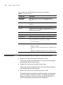
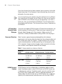
Table 1 Notice Icons
Icon
Notice Type
Description
Information note
Information that describes important features or
instructions
Caution
Information that alerts you to potential loss of data or
potential damage to an application, system, or device
10
CHAPTER : ABOUT THIS GUIDE
This manual uses the following text and syntax conventions:
Table 2 Text Conventions
Convention
Description
Menu Name >
Command
Indicates a menu item that you select. For example,
File > New indicates that you select New from the File
menu.
Monospace text
Sets off command syntax or sample commands and system
responses.
Bold text
Highlights commands that you enter or items you select.
Italic text
Designates command variables that you replace with
appropriate values, or highlights publication titles or words
requiring special emphasis.
[ ] (square brackets)
Enclose optional parameters in command syntax.
{ } (curly brackets)
Enclose mandatory parameters in command syntax.
| (vertical bar)
Separates mutually exclusive options in command syntax.
Keyboard key names
If you must press two or more keys simultaneously, the key
names are linked with a plus sign (+). Example:
Press Ctrl+Alt+Del
Words in italics
Documentation
Italics are used to:
n
Emphasize a point.
n
Denote a new term at the place where it is defined in the
text.
n
Highlight an example string, such as a username or SSID.
The 3WXM documentation set includes the following documents.
Wireless LAN Switch Manager (3WXM) Release Notes
These notes provide information about the system software release,
including new features and bug fixes.
Wireless LAN Switch and Controller Release Notes
These notes provide information about the system software release,
including new features and bug fixes.
Wireless LAN Switch and Controller Quick Start Guide
This guide provides instructions for performing basic setup of secure
(802.1X) and guest (WebAAA™) access, for configuring a Mobility
Domain for roaming, and for accessing a sample network plan in
3WXM for advanced configuration and management.
Documentation Comments
11
Wireless LAN Switch Manager Reference Manual
This manual shows you how to plan, configure, deploy, and manage a
Mobility System wireless LAN (WLAN) using the 3Com Wireless LAN
Switch Manager (3WXM).
Wireless LAN Switch and Controller Installation and Basic
Configuration Guide
This guide provides instructions and specifications for installing a WX
wireless switch in a Mobility System WLAN, and basic instructions for
deploying a secure IEEE 802.11 wireless service.
Wireless LAN Switch and Controller Configuration Guide
This guide provides instructions for configuring and managing the
system through the Mobility System Software (MSS) CLI.
Wireless LAN Switch and Controller Command Reference
This reference provides syntax information for all MSS commands
supported on WX switches.
Documentation
Comments
Your suggestions are very important to us. They will help make our
documentation more useful to you. Please e-mail comments about this
document to 3Com at:
[email protected]
Please include the following information when contacting us:
Document title
Document part number and revision (on the title page)
Page number (if appropriate)
Example:
Wireless LAN Switch and Controller Configuration Guide
Part number 730-9502-0071, Revision B
Page 25
Please note that we can only respond to comments and questions about
3Com product documentation at this e-mail address. Questions related to
Technical Support or sales should be directed in the first instance to your
network supplier.
12
CHAPTER : ABOUT THIS GUIDE
1
GETTING STARTED
This chapter contains information about recommended system
requirements you should meet for optimum 3WXM performance,
installing 3WXM client and 3WXM Services software, and an introduction
to using the 3WXM interface.
Hardware
Requirements for
3WXM Client
Table 3 shows the minimum and recommended requirements to run the
3WXM client in Windows.
Table 3 Hardware Requirements for Running 3WXM Client in Windows
Minimum
Recommended
Processor
Intel Pentium 4 2 GHz or
equivalent
Intel Pentium 4 3 GHz or
equivalent
RAM
512 MB
1 GB
Hard drive space
available
100 MB
200 MB
Monitor resolution
1024x768 pixels, 24-bit
color
1600x1200 pixels, 32-bit
color
CD-ROM drive
CD-ROM or equivalent
CD-ROM
.
14
CHAPTER 1: GETTING STARTED
Hardware
Requirements for
3WXM Services
Table 4 shows the minimum and recommended requirements to run the
3WXM Services in Windows.
Table 4 Hardware Requirements for Running 3WXM Services in Windows
Software
Requirements
Minimum
Recommended
Processor
Intel Pentium 4 2.4 GHz
or equivalent
Intel Pentium 4 3.6 GHz
or equivalent
RAM
1 GB
2 GB
Hard drive space available 1 GB
2 GB
Monitor resolution
1024x768 pixels, 24-bit
color
1600x1200 pixels, 32-bit
color
CD-ROM drive
CD-ROM or equivalent
CD-ROM
3WXM client and 3WXM Services are each supported on the following
operating systems:
Microsoft Windows Server 2003
Microsoft Windows XP with Service Pack 1 or higher
Microsoft Windows 2000 with Service Pack 4
You must use the English version of the operating system you select.
Operating system versions in other languages are not supported with
3WXM.
The following additional software is required for certain 3WXM features:
HP OpenView Network Node Manager 6.4—Must be installed prior to
3WXM if you plan to use 3WXM in your HP OpenView environment.
Adobe Acrobat Reader 5.x or later (or plug-in)—For reading the
Wireless LAN Switch Manager Reference Manual and release notes.
Web browser (for example, Microsoft Internet Explorer 5.x or 6.x or
Netscape Navigator 6.x or 7.x)—For displaying 3WXM Help, work
orders and inventory reports.
Preparing for Installation
Preparing for
Installation
User Privileges
15
Before you install 3WXM, make sure you have the appropriate
administrative privileges on the system and a license key if required. If you
plan to install the HP OpenView plug-in for 3WXM, which allows you to
integrate 3WXM into an HP OpenView environment, make sure that HP
OpenView is already installed.
Before you install 3WXM, make sure that you are logged in as a user who
has permission to install software, or as an administrator.
After you install 3WXM, you can configure 3WXM access privileges for
the user accounts on the machine. Likewise, you can configure access
privileges for 3WXM Services, if installed. Access privileges for the 3WXM
client are completely independent of access privileges for 3WXM Services,
and are configured separately.
Serial Number,
License Key and
Activation Key
The serial number is generated automatically when the 3WXM software
is installed.
The license key is included with your 3WXM software packaging. You will
need a separate license key for each host on which you plan to run
3WXM. The license supplied with 3WXM allows you to manage up to 10
wireless switches. If you plan to manage more wireless switches, you will
also need an Unlimited Device license key (3CWXMUPA). You will need a
separate Unlimited Device license key for each host on which you plan to
run 3WXM to manage more than 10 devices.
If you do not have a license key, you can run 3WXM for 30 days. Once
this trial period is over you will need to purchase a license to continue
running the 3WXM software.
When you initially run the 3WXM software, it will ask if it is to be run as a
trial or as a fully licensed version. In the latter case, it will then ask for the
license key. The software will then display the serial number and ask for
an activation key.
To obtain an activation key, you must register the product with 3Com. If
you press the Get Activation Key button, your web browser will be
automatically launched at the correct pages for registering the product.
Once registration is complete, your activation key will then be displayed
and e-mailed to you.
16
CHAPTER 1: GETTING STARTED
Once the activation key has been accepted, you may enter an Unlimited
Device license key. This will require its own activation key, which can be
obtained in the same manner.
If you are registering your product using the web browser on a different
host, and you wish to register for the 30-day trial, then you will need to
select 3CWXMA as the software that you are registering. If you have a
license key, then you should select 3CWXM10A. This will register both
the software and the license. The Unlimited Device license is registered as
3CWXMUPA.
HP OpenView
Network Node
Manager
If you want to integrate 3WXM into your HP OpenView environment, you
have the option of installing the HP OpenView plug-in required to use
Network Node Manager with 3Com products. Make sure that HP
OpenView is already installed before installing 3WXM with the plug-in.
Resource Allocation
Table 5 contains general recommended guidelines for hardware
requirements and memory allocation based on the number of radios and
WX switches your server will support. A larger number of WX switches
implies more connections and data processing, and consequently, more
CPU is required. A larger number of radios implies more data (including
client sessions) which requires more RAM and storage.
Table 5 Recommended Server Hardware Allocation
Number of
Radios
1-25 WX Switches
25-50 WX Switches 50+ WX Switches
1 – 1000
- 2.4 MHz P4
- 2.8 MHz P4
- 3.2 MHz Xeon
- 500 MB RAM
- 500 MB RAM
- 1 GB RAM
- 1 GB HD
- 1 GB HD
- 1 GB HD
- 2.4 MHz P4
- 3.0 GHz P4
- 3.6 GHz Xeon
- 1 GB RAM
- 1 GB RAM
- 2 GB RAM
- 2 GB HD
- 2 GB HD
- 2 GB HD
1000 – 2000
3WXM Services
Options
3WXM Services can be installed either in standalone mode or shared
mode. Standalone mode is when 3WXM client and 3WXM Services are
installed on one machine. Standalone mode is primarily used for trying
out 3WXM, while shared mode is used in a working environment. In
shared mode, the administrator sets up 3WXM Services on a single host
(typically with more resources) and other hosts with the client 3WXM
Preparing for Installation
17
application share 3WXM Services to access network plans and monitoring
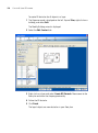
information. See Figure 1.
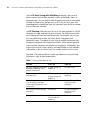
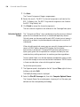
Figure 1 3WXM Services in Shared Mode
During the 3WXM installation, you can select to install the 3WXM
Services and 3WXM client, or the client only. If you select the option that
installs 3WXM Services, the services are installed with default settings
that are adequate for getting started.
Network plans are stored on the server. By default, only local access is
allowed. Remote clients cannot access the server unless you enable
remote access.
To learn more about RF monitoring and client monitoring, see
“Managing and Monitoring Your Network” on page 143.
18
CHAPTER 1: GETTING STARTED
Installing 3WXM
The same 3WXM install program installs either just the 3WXM client or
both the 3WXM client and 3WXM Services.
This section contains information about the following topics:
Unpacking Files
“Unpacking Files” on page 18
“Using the Installation Wizard” on page 18
To unpack files on Windows systems:
1 Insert the 3WXM CD in the CD-ROM drive. If Autorun is enabled, wait
briefly for the install program to start. For more information about using
the installation wizard, see “Using the Installation Wizard” below.
If Autorun is disabled, follow these steps:
a In Windows Explorer, navigate to your CD-ROM drive.
b In the Windows\VM directory, double-click install.exe.
The Introduction page of the 3WXM installation wizard appears.
2 Click Next to display the Choose Installation Type page of the installation
wizard, and go to “Using the Installation Wizard”.
Using the Installation
Wizard
To use the Installation Wizard:
1 On the Choose Installation Type page, choose one of the following:
To install both the 3WXM server and the client, click the 3WXM
Services icon.
To install only the 3WXM client, click the 3WXM client icon.
For detailed installation instructions, see “Installing 3WXM” in the
Wireless LAN Switch Manager Reference Manual.
Start the 3WXM Services
The 3WXM Services are automatically started when you install it on a
Windows system.
Installing 3WXM
19
Connect 3WXM Clients to 3WXM Services
To connect the client to Services:
1 Select Start > Programs > 3Com > 3WXM > 3WXM. The 3WXM
Services Connection wizard is displayed.
2 Enter the IP address or fully-qualified hostname of the machine on which
the service is installed.
If 3WXM Services is installed on the same machine as the one you are
using to run 3WXM client, enter 127.0.0.1 as the IP address. This is a
standard IP loopback address.
3 Specify the service port, if different from the port number in the Service
Port listbox.
The port number used by the monitoring service must not be used by
another application on the machine where the monitoring service is
installed. If the port number is used by another application, change the
port number on the monitoring service. (See “Configure 3WXM Services”
below.)
4 Click Next to connect to the server.
5 If the Certificate Check dialog is displayed, click Accept.
If you left the Open Network Plan option on the 3WXM Services
Connection dialog selected, the server opens a new (blank) network plan.
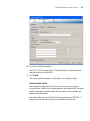
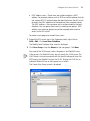
Configure 3WXM Services
You can change the properties of 3WXM Services.
If a firewall is enabled on the host where you install 3WXM Services,
3WXM Services will not be able to communicate with 3WXM client or
with WX switches unless the firewall is configured to allow through
traffic for the SSL and SNMP ports (443 and 162 by default).
20
CHAPTER 1: GETTING STARTED
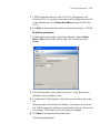
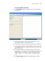
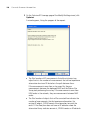
To configure 3WXM Services:
1 Select Tools > 3WXM Services Setup dialog box from the 3WXM main
tool bar. The 3WXM Services Setup wizard is displayed.
2 You can optionally configure the following:
Select the arrow buttons to change the HTTPS Server Port, which is
the port on which 3WXM Services listens for requests from 3WXM
client.
Select the arrow buttons to change the SNMP Trap Receiver Port,
which is the port on which SNMP traps are received. Also select the
trap type (SNMPv1 or SNMPv3) you want 3WXM Services to receive
from WX switches.
Installing 3WXM
21
On each switch in the network plan, you must enable notifications and
configure 3WXM Services as a notification target (trap receiver).
3WXM Services does not start listening for SNMP notifications from
switches until you save the network plan.
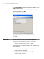
From the Key Store area of the window, specify security settings.
From the Access Control area, define user accounts. For more
information about access control, see “3WXM Access Control” on
page 21.
By default, a username and password are not required to access 3WXM
Services from 3WXM client, but only local connections (connections from
client to server on the same host) are allowed. To change these settings,
use the Service Settings tab of the 3WXM Services Setup dialog.
To select monitoring settings:
All monitoring options are enabled by default. You do not need to enable
them and you do not need to specify the switches you want to monitor.
However, for 3WXM Services to receive trap data from WX switches,
SNMP notifications must be enabled on the switches. (See “Deploy Your
Configuration” on page 144.)
To start gathering data for monitoring, deploy your configuration to the
network. For information about deploying your configuration, see
“Deploy Your Configuration” on page 144.
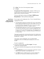
3WXM Access Control
You can create a user account with administrator, provision, or monitor
privileges. See Table 6 for privilege definitions.
Table 6 User Privilege Levels
Privilege Level
Access Control
Configuration
Monitoring
Administrator
yes
yes
yes
Provision
no
yes
yes
Monitor
no
no
yes
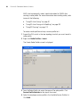
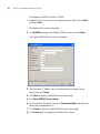
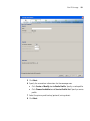
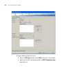
To configure access control:
1 Select Tools > 3WXM Services Setup from the 3WXM main tool bar.
The 3WXM Services Setup window is displayed.
2 In the Access Control area of the window, deselect Allow all users.
22
CHAPTER 1: GETTING STARTED
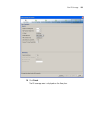
3 Select Add Admin Account, Add Provision Account, or Add Monitor
Account. A dialog box is displayed.
4 Enter the account name and the password and click OK.
5 To remove an account, click Remove Account.
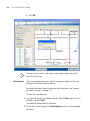
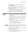
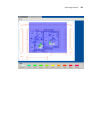
3WXM Interface
Display the Main
Window
This section contains the following topics:
“Display the Main Window” on page 22
“Using Menu Bar and Toolbars” on page 24
“Setting Preferences” on page 24
“Easy Configuration Using Wizards” on page 25
“View Topology” on page 25
“Shortcut to Wizards and Editing Properties” on page 26
“Shortcut to Wizards and Editing Properties” on page 26
“Getting Help” on page 27
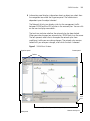
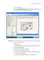
When you open a network plan or create a network plan using the
Network Planning wizard, 3WXM displays the Main window. The Main
window is divided into four panels (see Figure 2 on page 23):
1 Organizer panel displays a network tree representing your WLAN’s
devices and configurations on those devices. You can use it to navigate to
Policy configurations, Equipment within your network, and network Sites.
When you select a device or configuration in the tree, the
context-sensitive information about the device or configuration is
displayed to the right in the Content and Information panels. Select the
Details checkbox at the top of the Organizer panel to display detailed
configuration information about items in the tree.
2 Content panel displays context-sensitive information about the device or
configuration selected from the tree in the Organizer panel. From the
Content panel, view 3Com devices and their status, verify 3Com device
configurations in the network plan and in the network, and display event
logs and Rogue detection results.
3 Alerts panel displays a summary of alerts, including network and
configuration verification, Rogue detection, and local and network
changes. Click on a summary to display details.
3WXM Interface
23
4 Information panel displays information about an object you select from
the navigation tree under the Organizer panel. The information is
dependent upon the object selected.
The Network Activity icon displays statistics for management traffic
between 3WXM and the WX switches in the network plan. You can click
on the icon to display more details.
The Lock icon indicates whether the network plan has been locked.
When you make changes to a network plan, 3WXM locks it on the server.
The lock prevents other clients who open the network plan from
modifying it while you are making changes. The network plan remains
locked until you save your changes, after which the lock is released.
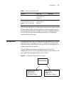
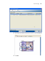
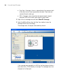
Figure 2 3WXM Main Window
Content panel
Organizer panel
Toolbar
Lock
icon
Object Details panel (hidden by default)
Alerts panel
Network Activity icon
24
CHAPTER 1: GETTING STARTED
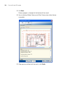
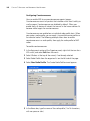
Using Menu Bar and
Toolbars
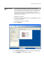
The Main window and individual panels have a menu bar at the top to
select certain actions. Select an item from the menu bar, then select an
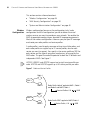
action from the dropdown menu. See Figure 3.
Figure 3 Menu Bar with Dropdown Menu
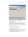
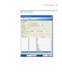
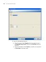
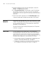
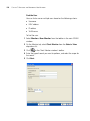
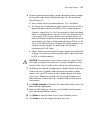
Setting Preferences
You can set network and user interface preferences, as well as
preferences for save interval and autosave, certificate handling,
RF monitoring, and logging.
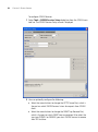
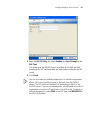
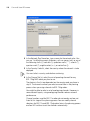
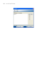
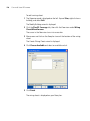
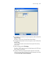
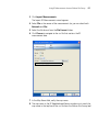
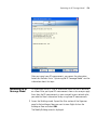
1 Select Tools > Preferences from the 3WXM main tool bar.
The Preferences wizard is displayed.
Figure 4 Preferences Wizard
2 Select any of the tabs, make modifications in the fields, and select
Reset All to reset preferences.
3WXM Interface
Easy Configuration
Using Wizards
25
Wizards help walk administrators through configuration steps. There are
several wizards in the 3WXM application.
Enter the required fields and click Next at the bottom of the wizard to
display the next step. Click Cancel to discard any changes made with the
wizard. When you are done, click Finish to save changes.
You can right-click on many objects to display the Insert option. Select
Insert to create a new object that is a “child” of the selected object.
View Topology
You can display a topology view of managed devices in your WLAN and
their relationships to each other. You can also click on the devices in the
topology view to display summary monitoring information about each
one.
To display a topology view of your network:
1 In the Equipment section of the Organizer panel, select a mobility domain
or a WX switch.
2 From the main 3WXM window, select Monitor > New Monitor.
3 Select Explore from the drop-down list in the Monitor tab. The topology
view of the selected object is displayed.
26
CHAPTER 1: GETTING STARTED
Shortcut to Wizards
and Editing
Properties
Shortcuts are built into the 3WXM interface to quickly access wizards and
for editing properties for selected objects.
To use shortcuts:
1 Right-click an object from the topology tree in the Organizer panel.
2 Select one of the options displayed. You can select Edit to edit object
properties, or Insert to display a wizard that assists you to create a new
object.
3WXM Interface
Getting Help
27
Click Help from the Main menu bar to access different types of help:
1 Select Help > 3WXM Help to display HTML help about configuring and
using 3WXM.
2 Select Help > Licensing to view product licensing information, or to add
an Unlimited Device license to the installation.
3 Select Help > Report Problem to report a problem to 3Com Technical
Support.
4 Select Help > About 3WXM to display information about 3WXM and to
display the Release Notes. You also can click Force GC (garbage
collection) to free resources.
28
CHAPTER 1: GETTING STARTED
2
PLANNING AND MANAGING YOUR
WIRELESS NETWORK WITH
3WXM
This chapter contains information about planning and managing your
wireless network with 3WXM. Planning your wireless network is highly
recommended because it not only helps you configure and deploy it, but
also aids in scaling and monitoring your network. 3Com provides you
with flexible tools to assist with network planning.
Overview
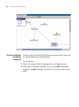
You plan your wireless network to support the services you want to offer
your employees, guests, or customers. Figure 5 describes the process you
will follow to establish services in your company or organization,
beginning with determining the services you want to offer. Each step in
the process is described in this chapter.
Figure 5 Process to Establish Wireless Services
START
Determine which
services to
provide
Configure
services
Optimize
services
Plan for network
equipment and
coverage
Generate work
order and install
equipment
Monitor
services
Deploy
services
30
CHAPTER 2: PLANNING AND MANAGING YOUR WIRELESS NETWORK WITH 3WXM
Which Services To
Provide?
A service is a concept (not a selectable item in the 3WXM interface) that
represents a set of options you configure and deploy on your wireless
network.
You configure services to support the different levels of network access
you need to provide. For example, a service configured to support
employee access will have different options configured to provide greater
access to the network. In contrast, a service configured for guest access
typically restricts users to limited or no internal network access, but easily
provides a gateway connection to the Internet.
A service can be fully isolated and independent of other services on the
network (multi-hosted access is typically isolated), or you can reuse part of a
service configuration for another service you want to provide. Each service
has potential authentications (802.1X, web page, MAC address, or “last
resort”) and potential encryptions (802.11i, WPA, WEP, or unencrypted).
The purpose of this section is to provide information about services that you
can configure using 3WXM. Understanding the services you can configure
with 3WXM is the first step in planning and configuring your network.
The first step you need to do when planning your wireless network is to
determine which services your organization requires. The three common
types of services are:
Employee access
Guest access
Voice over Wireless IP (VoWIP)
Employee access is typically secure, encrypted access to the wireless
network. Guest access is access (possibly unencrypted) for visitors at your
location. If you intend to resell services to other providers, you will need
to provide multi-hosted access.
Determining the services you will need at the beginning of the planning
process results in configuration data. The configuration data is used to
create service profiles and AAA rules for each service. A service profile is a
subset of a radio profile. A radio profile is a common set of configuration
parameters that can be applied to many MAP radios.
See “Create a Service Profile” on page 94 for information about
configuring services.
Network Plan
Network Plan
31
A network plan is the workspace in 3WXM you use to design a wireless
network.
You can better manage and visualize your network topology by creating
a detailed and accurate network plan.
You can start by creating a device-oriented (WX switches and MAPs) view
of your network without any geographic information about your site—no
floor dimensions, building material information, or RF obstacle
information. You can go a step further and provide some geographic
information by adding floor dimensions, your RF coverage area, and
some attenuation information, such as elevator shafts or internal
concrete walls. If you want to enjoy the full benefits of network
monitoring and visualization, you can create a detailed network plan. This
is done by importing detailed building and floor plans into 3WXM,
defining RF obstacles, and defining the quality of coverage (traffic
engineering parameters) you want for specific RF coverage areas.
RF Coverage Area
An RF coverage area is the geographical area in which IEEE 802.11 radios
provide wireless services.
This section describes the three techniques you can use for RF coverage.
By understanding available RF coverage planning techniques, you can use
the technique that meets your organization’s requirements.
There are three techniques you can use to get your wireless network
started:
RF Auto-Tuning lets you use the default auto tuning feature to select
power and channel settings for RF signals in your RF coverage area.
You upload the WX switches into 3WXM, configure the MAPs, enable
RF Auto-Tuning, and deploy.
32
CHAPTER 2: PLANNING AND MANAGING YOUR WIRELESS NETWORK WITH 3WXM
RF Auto-Tuning with Modelling, as with the RF Auto-Tuning
technique, lets you set the auto tuning feature to adjust power and
channel settings to provide RF signals to the coverage area for your
users. Enhance the auto tuning feature by providing modelling
information about your geographic location. By providing some
information about your buildings and floors, you add enough details
into 3WXM so that your can better visualize your network topology
and support improved monitoring at your site.
RF Planning is a technique you can use to create a detailed network
plan that provides powerful monitoring and visualization benefits.
Unlike RF Auto-Tuning or RF Auto-Tuning with Modelling, you do not
rely on the auto tuning feature. Instead, you fully model your
geographic location with detailed information about your floors, and
specify your RF coverage areas and your RF obstacles.
Each of these methods is described in the sections that follow.
RF Auto-Tuning
To use the RF Auto-Tuning technique:
Physically place WX switches and the MAPs in their desired locations.
Upload a WX switch configuration and deploy it
Enable the RF Auto-Tuning feature
This is a great way to install a WX switch and some MAPs, and observe
how the network operates. The RF Auto-Tuning plan is best suited to
networks containing fewer MAPs.
RF Auto-Tuning with
Modelling
To use the RF Auto-Tuning with Modelling technique, you add to the RF
Auto-Tuning technique by providing some geographical modelling about
your building, floors, and RF coverage area. You also add RF obstacle
information for major obstacles (like concrete walls, windows, and
elevator shafts) that affect attenuation—the quality of RF signals emitted
from and received by the MAPs.
By adding geographical modelling, you will be able to manage your
network in the context of that geographical information. For example,
you will be able to manage your network overlaid on a floor plan, versus
managing an abstract logical group of switches and MAPs.
RF Coverage Area
RF Planning
33
To do RF Planning, you provide detailed information about your site and
buildings by importing AutoCAD DXF™, AutoCAD DWG, JPEG, or GIF
floor plan files of the buildings into 3WXM.
As you import the floor plans, you can modify them to add or remove RF
obstacles. 3WXM includes a library of attenuators for building obstacles.
The library includes doors, walls, ceilings, and other physical obstructions
that you can select. Attenuators can be defined by height, width, type of
building material. 3WXM factors in the impact these objects have on how
the radio frequency (RF) signals flow through a given site.
If the network contains third-party APs, you can enter information for
these APs so that 3WXM takes the APs into account when calculating the
placement (and optionally, the channel and power settings) of the 3Com
MAPs.
By using this technique, you receive these substantial benefits:
Which Planning
Method Should I Use?
Instead of you making a “best guess” as to how many MAPs you
require for the desired coverage and where MAPs should be placed,
3WXM automatically calculates how many MAPs you need and where
to place MAPs for optimal positioning.
You can generate a deployable work order to help installers place WX
switches and MAPs.
You automatically receive a deployable configuration that includes
optimum power and channel settings.
You enjoy more accurate monitoring options and network
visualization based on the additional geographic modelling
information loaded into 3WXM.
The more detailed your network plan, the better you will be able to
manage and monitor the network. However, there are other
requirements organizations should consider.
3Com suggests you use the RF Auto-Tuning technique if you are
installing MAPs without consideration to blanket coverage, throughput
concerns, or the number of users for whom service will be provided. RF
Auto-Tuning is ideal for small areas; for example, coverage that only
requires a few MAPs, or widely dispersed areas in a building, such as
conference rooms.
34
CHAPTER 2: PLANNING AND MANAGING YOUR WIRELESS NETWORK WITH 3WXM
Use the RF Auto-Tuning with Modelling technique if you want to
better monitor your wireless network in terms of buildings, floors, or
coverage areas. You may only be able to locate inaccurate or incomplete
building and floor plans (perhaps only a JPEG file), but with even a bit
more geographic modelling of your site, you boost your ability to manage
and visualize your network.
Use RF Planning when you want to use all the tools provided in 3WXM
to deploy, manage, and monitor your network. You likely have multiple
constituencies of users you need to consider; for example, sets of users
that are mobile and wireless that have specific throughput and
bandwidth needs. One group of users may be mobile and require high
throughput performance (a higher bandwidth), while another group of
users are more stationary and require less throughput. Additionally, you
may be planning for future capacity, and need to add as much detailed
information as you can about your site in order to plan for the future.
See Table 7 for some guidelines to help you determine what planning
technique is right for your organization.
Table 7 Planning Techniques to Use
Concern
If yes, use
If No, use
Do I have adequate time to add
geographic modelling and RF
obstacle information?
RF Auto-Tuning with
Modelling
RF Auto-Tuning
Can I locate accurate building
and floor plans?
RF Planning or
RF Auto-Tuning with
Modelling
RF Auto-Tuning with
Modelling
Do I need to plan for capacity of RF Planning
users or quality of coverage
(traffic engineering concerns) for
certain users?
RF Auto-Tuning or RF
Auto-Tuning with
Modelling
Do I need to visualize coverage
accurately?
RF Planning
RF Auto-Tuning or RF
Auto-Tuning with
Modelling
Do I need to locate users?
RF Planning or RF
Auto-Tuning with
Modelling
RF Auto-Tuning
Configuration
35
Table 7 Planning Techniques to Use
Concern
If yes, use
If No, use
Do I need to locate rogue APs?
RF Planning or RF
Auto-Tuning with
Modelling
RF Auto-Tuning
Do I want to better monitor my
wireless network in terms of
buildings, floors, or coverage
areas?
RF Planning or RF
Auto-Tuning with
Modelling
RF Auto-Tuning
If RF Planning does not fit your requirements now, you can always use the
RF Planning technique in the future when you have the need, the time,
and the necessary floor plans available. You also can leverage the data in
RF Auto-Tuning and convert these RF measurements to configured
baseline values for planning.
Configuration
This section describes the main areas of the 3Com network (WX switch
and MAPs) you will configure in 3WXM. It provides you with overview
information about the software so that you can plan a configuration to
support the services you require.
You will configure the wireless configuration and AAA security
configuration for each service you provide on your wireless network. You
also create a basic configuration for the WX switch.
Figure 6 Configuration Required for Each Service
Wireless Service
Wireless Configuration
- Radio Profile
- Service Profile
- Encryption Choices
AAA Security Configuration
- AAA methods
- Rules
- Authentication choices
36
CHAPTER 2: PLANNING AND MANAGING YOUR WIRELESS NETWORK WITH 3WXM
This section contains information about:
Wireless
Configuration
“Wireless Configuration” on page 36
“AAA Security Configuration” on page 38
“System and Administration Configuration” on page 40
Wireless configuration focuses on the configuration tasks (radio
configuration and AAA configuration) you do to deliver the virtual
wireless services you want to provide on your network. You enable the
MAPs to operate according to your planned RF coverage requirements.
Most of the wireless configuration is done as you plan your RF coverage
and create your radio profiles and service profiles.
A radio profile is used to apply common settings to multiple radios, and
each radio profile can support up to 32 service profiles, one for each
service you want to support. You specify in the service profile an SSID for
each service and the type of encryption mechanisms to be used by the
MAP radios. This gives the radio the potential to look like 32 different and
independent MAPs. See Figure 7.
AP7250, AP8250, and AP8750 support up to eight service profiles per
radio. AP2750 and AP3750 support up to 32 service profiles per radio.
Figure 7 Radio and Service Profiles
Radio 1
MAP 1
Radio 2
Radio Profile “default” applied to MAP 1, Radio 1
and Radio 2 and MAP2, Radio 1
Service Profiles 1-32
SSID
Radio 1
MAP 2
Radio 2
Radio Profile “EBC” applied to MAP2, Radio 2
Service Profile, 1-32
SSID
Configuration
37
You must configure a radio profile to set attributes that you can apply to
multiple radios. Rather than configuring each radio individually, you
create a radio profile and apply it to multiple radios that you select. You
can also create a radio profile as part of a domain policy and apply it to
MAP access points on different WX switches.
The radio profile can contain RF Auto-Tuning settings and IEEE 802.11
settings that control how the data is received and transmitted. You can
select RF Auto-Tuning in the radio profile to apply AutoRF settings
(enable or disable auto tuning of power and channels) to radios en masse
via the radio profile. AutoRF enabled through the radio profile to multiple
radios can be easily disabled, too, should you want to go to full RF
planning. You can set specific IEEE 802.11 settings, such as beacon, DTIM
intervals, and the fragment threshold to control how packets are
transmitted.
A default radio profile named “default” is provided and cannot be
deleted.
For each service you want to provide, you configure the following items
in a service profile:
The SSID name
SSID advertisement (whether the SSID name is beaconed)
Whether the SSID name is encrypted or clear (not encrypted)
Web page (if using WebAAA)
Multiple encryption choices (Dynamic/static WEP, WPA, WEP + WPA,
802.11i)
You also must configure AAA security configuration items for each
service. For more information, see “AAA Security Configuration” on
page 38.
Which encryption you use depends on the type of services you’re
offering. Employee access is typically encrypted, guest access is typically
clear (no encryption), and multi-host or “multiple virtualized services”
service can be encrypted, with each SSID being matched with its own
service profile.
38
CHAPTER 2: PLANNING AND MANAGING YOUR WIRELESS NETWORK WITH 3WXM
If services are being used for customer corporate entities (e.g. different
airlines on an airport wireless net), then they would probably use 802.1X
and strong encryption with web guest access for their airport club guests.
If the services are being used to advertise multiple wireless service
providers (WISP), such as T-MobileTM, Wayport ®, and Boingo WirelessTM,
then these services would probably be completely open. However, they
would likely be assigned to their own dedicated subnet containing their
proxy server/billing gateway.
AAA Security
Configuration
An administrator can control the way in which users access the network.
For each service you provide, you can configure unique authentication,
authorization, and accounting (AAA) security features, creating an
entirely virtualized wireless service. For each service, you configure:
Multiple authentication choices (802.1X, Web, AAA, MAC
authentication, Bonded Auth, open)
AAA methods (up to four RADIUS server groups, or a local database
on the WX switch)
Authentication
Authentication is the method of determining whether a user is allowed
access to your network. Users can be authenticated by a RADIUS server
(pass-through) or by the WX switch local database (local). The WX switch
can also assist the RADIUS server by performing the Extensible
Authentication Protocol (EAP) processing for the server (offload).
To authenticate users, you will need to configure users either in the local
database or on RADIUS servers. Each user will have a username,
password, and RADIUS and/or vendor-specific attributes (VSAs). You will
also need to configure authentication rules (802.1X, MAC, last-resort, or
web authentication).
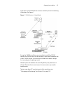
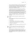
See Figure 8 on page 39 to see a flowchart representing the
authentication process. Generally, 802.1X authentication is attempted
first. If the user fails, then MAC authentication is attempted. If this fails,
then last resort and web authentication is used. For a service profile, you
specify either web authentication, last-resort, or none in the
auth-fall-thru box. You can only select one.
Configuration
39
Figure 8 Authentication Flowchart for Network Users
Client associates with 3Com radio
or requests access from wired authentication port
Client requests
encrypted SSID?
Yes
802.1X rule that
matches SSID?
Client
responds
to 802.1X?
Yes
No
No
No
Yes
Authent.
Allow
succeeds? Yes Client
No
Refuse
Client
Authent.
Allow
succeeds? Yes Client
MAC rule that
matches SSID?
No
No
Use fallthru authentication
last-resort?
Last-resort rule that
matches SSID?
Yes
No
web?
No
none?
Yes
Refuse
Client
Authent.
Allow
succeeds? Yes Client
No
No
Refuse
Client
Refuse
Client
Web Auth rule that
matches SSID?
Yes
Yes
Yes
Authent.
Allow
succeeds? Yes Client
No
No
Refuse
Client
Refuse
Client
40
CHAPTER 2: PLANNING AND MANAGING YOUR WIRELESS NETWORK WITH 3WXM
Authorization
Authorization is the method for providing users with specific rights to the
network by associating attribute-value (AV) pairs to the user. AAA
authorization works by assembling a set of attributes that describe what
the user is authorized to perform. These attributes are compared to the
information contained in a local database or on a RADIUS server for a
given user and the result is returned to the WX switch to determine the
user’s actual capabilities and restrictions.
You can configure attributes, such as the time of day or specific VLAN
access. You can also control access using security access control lists
(ACLs), Mobility ProfilesTM, and Location Policies. Security ACLs permit or
deny traffic based on IP protocol, IP addresses and, optionally, TCP or
UDP port. They also can be used to set type-of-service (ToS) and
class-of-service (CoS) values in a packet. Mobility Profiles contain
attributes to allow or deny access to specific parts of the network for a
specific user or group of users. Location Policies are an ordered list of
location policy rules based on a user glob, VLAN, and/or ports. A Location
Policy can be configured if you need to override the configured AAA user
authorization attributes locally for a specific WX.
Accounting
Accounting collects and sends information used for billing, auditing, and
reporting—for example, user identities, connection start and stop times,
the number of packets received and sent, and the number of bytes
transferred. You can track sessions through accounting information
stored locally or on a remote RADIUS server. As network users roam
throughout the network, accounting records track them and their
network usage.
System and
Administration
Configuration
A Mobility Domain is a collection of WX switches that work together to
support roaming users. One of the WX switches is defined as a seed
device, which distributes information to the other WX switches defined in
the Mobility Domain.
A Mobility Domain allows users to roam geographically from one WX
switch to another without losing network connectivity. Users connect as
a member of a VLAN through their authorized identities.
Configuration
41
Using the default Mobility Domain or one you create, add a WX switch to
the network plan that is a member or seed device of the Mobility
Domain. You can then configure that WX, or you can just add it to the
network plan, and configure it later. After you configure the WX switch
and verify its configuration, you can deploy it to the network.
You can create the following types of WX switches:
WX4400—Provides four dual-interface gigabit Ethernet ports. Each
port has a 1000BASE-TX copper interface and a Gigabit interface
converter (GBIC) slot for insertion of a 1000BASE-SX or 1000BASE-LX
fiber-optic interface.
WX1200—Provides eight 10/100 Ethernet ports, six of which support
PoE.
WXR100—Provides two 10/100 Ethernet ports, one of which supports
PoE.
You perform the following tasks to create and initially configure a WX
switch:
Configure basic WX switch properties.
Configure WX switch connection information.
Configure boot information.
Configure Basic WX Switch Properties
To configure basic WX switch properties, you specify a name, select a
model, select its location by wiring closet, and select the Mobility System
Software (MSS) you want to run on the switch. Optionally, you can select
an MSS image to download when you deploy changes to the WX.
You also can specify if the switch is managed. A WX switch that is
physically installed as well as configured can be managed. You can
deploy configuration changes only to managed devices, and 3WXM
periodically checks the managed WX switches in the network for
changes. You also can fully configure a switch without it being physically
installed (unmanaged). Having an unmanaged device in your network
plan may be useful for predeployment purposes.
42
CHAPTER 2: PLANNING AND MANAGING YOUR WIRELESS NETWORK WITH 3WXM
Basic configuration also includes specifying how you will manage the
switch. You can manage it through HTTPS, telnet, and Secure Shell (SSH).
You also can enable monitoring using the Simple Network Management
Protocol (SNMP) to exchange information about network activity
between your network devices.
For more information about configuring basic WX switch properties, see
“Perform Basic Administrative Tasks” on page 146.
For detailed information about configuring basic WX switch properties,
see the Wireless LAN Switch and Controller Quick Start Guide.
Configure WX Switch Connection Information
You need to supply connection information for the WX switch on both
the WX switch and in 3WXM when you make the WX a managed device.
Connection information includes the IP address of the switch and how it
will connect to the backbone; for example, by means of a VLAN or a port.
Configure Boot Information
You select the software image that the WX will use when reset, or
optionally, the configuration file the WX will use when reset.
Equipment
Installation
To physically install a WX switch:
1 Unpack and rack the WX switch in the wiring closet or data center
location.
2 Plug the WX switch electrical cord into a power outlet.
3 Connect a network access cable from your existing network to one of the
Ethernet ports on the switch (10/100 or Gigabit Ethernet, depending on
the WX model and available interfaces on the network).
Remember the port number you used. You will need to know this when
performing the initial setup of the switch.
4 Connect a serial interface to the console port of the WX switch to access
the console’s CLI for initial setup.
Deployment
43
To physically install MAPs:
1 Instruct the cabling installer to run the Cat. 5 Ethernet cable from the
closest wiring closet to intended location of the MAP.
2 Unpack the MAP, and select the appropriate mounting kit for your
installation location.
3 Install the MAP at the indicated location on the floor.
4 Connect the Cat 5. Ethernet cable(s) to the MAP.
5 At the wiring closet, connect the MAP to the infrastructure equipment:
a If you are directly connecting the MAP to a WX switch, plug the other
cable end(s) to the indicated port(s).
b If you are indirectly connecting the WX to the switch, plug the other
cable end(s) to an available network port on the wiring closet switch.
If the switch does not supply PoE, then ensure that a mid-span PoE
device is inserted in-line with the connection.
Deployment
Deployment is when WX configuration information in the 3WXM
network plan is sent to your WX switch.
Configuration changes are collected in 3WXM when you save them, but
are not applied to WX switches until you send the configuration to the
WX switch and deploy the configuration to your network. Any changes
you make to your network in 3WXM are saved, but not applied to your
network until they are deployed. This method makes it easy to apply
configurations simultaneously to multiple WX switches, or you can deploy
changes to a single WX switch.
44
CHAPTER 2: PLANNING AND MANAGING YOUR WIRELESS NETWORK WITH 3WXM
Management and
Monitoring
Understanding the management and monitoring tools available in 3WXM
can help you to quickly identify and correct problems in your wireless
network, as well as to provide you with the statistics and reporting
information you need to optimize your network.
This section discusses the following management and monitoring
features:
Network Status
Network Status
RF monitoring
Client monitoring
Rogue detection
Event logging
Verification
Reporting
3WXM provides summary status on devices in the network at the mobility
domain, switch or MAP level. View the summary status as the initial step
in monitoring. Summary status displays the operational status of WX
switches, MAP access points, and their radios (whether they are up or
down).
In addition, 3WXM collects network statistics for devices, including
system-level events and statistics for the wired network.
The Alerts panel in the bottom, left panel in 3WXM displays top-level
status information. The Alerts panel provides you with summary error and
warning information for the following areas:
Configuration—indicates network plan configuration issues
Network—indicates managed network issues
Rogue detection—identifies the number of rogue APs detected
Local changes—indicates changes in 3WXM that can be deployed to
the network
Network changes—indicates configuration changes in the network
Management and Monitoring
45
You can display a topology view of your network, including the state and
relationship of devices. You can right-mouse click on a device in the
topology to display the status of that device. The display can include the
wired network, third-party APs, and rogue access points (access points
that are not authorized to operate in your network).
You also can set thresholds for events. If the threshold is crossed, the
affected device is flagged, and a star is placed beside the parameter that
triggered the threshold.
RF Monitoring
RF monitoring provides you with current and historical information about
your radio health and activity. Data collected for the RF environment and
the RF neighborhood includes the following items:
RF environment
Channel
Noise
CRC errors
PHY errors
Packet retransmissions
Percent utilization
RF neighborhood
Transmitters (heard by this radio)
Listeners (who heard this radio)
Neighbors
BSSID to SSID mapping
Channel
RSSI
Statistics collected for the RF environment provides data on a per-channel
basis. You can view noise levels, cyclic redundancy check (CRC) and PHY
errors, packet retransmissions and percent utilization.
Data collected for the RF neighborhood displays the neighboring radios.
This information can be viewed as a list of radios heard by a particular
radio, as well as a list of radios who can hear a particular radio.
46
CHAPTER 2: PLANNING AND MANAGING YOUR WIRELESS NETWORK WITH 3WXM
You also can display trending information on a per-radio basis. Trending
collects radio statistics and charts them on a time basis. For example, you
could display average throughput rates for the previous 30 days, week, or
day. You can display and print the charts from 3WXM, as well as
generate a report.
Client Monitoring
Client monitoring provides current and historical information about the
clients using your network, including client activity, watch list clients,
current client sessions, and the ability to locate clients at your site. 3WXM
displays the data that WX switches collect on user sessions—either for a
single user, users associated with a MAP, users associated with a specific
radio, or users added to a watch list.
By viewing monitoring information for a user or a group of users, you can
troubleshoot problems originating from bandwidth constraints or
roaming patterns. You can collect statistics and view reports on:
Rogue Detection
Client associations, authentication, and authorization failures
Client activity, such as roaming and successful authorization
Current session status, location history, and statistics
Specifics on users over a period of time; information can be gathered
up to 30 days for session status, location history, client errors, and
client activity on users you place on the watch list
A rogue AP is an access point that is not authorized to operate in or near
your network. You can use RF countermeasures to deny service to or
from a targeted rogue AP, and render them ineffective. Once a rogue AP
is detected and reported, the closest 3Com MAP is assigned to perform
RF countermeasures. By spoofing various 802.11 control messages, the
MAP’s countermeasures disrupt association and authentication attempts
to the rogue AP by any new clients. This also disrupts any active
communications between any existing client and rogue AP.
You can collect and statistics and view reports on:
Current rogue list, aggregated for the whole network
Current hour rogue list
Current day rogue list
30 days of rogue history, using best listener data
Management and Monitoring
47
Rogue lifecycle events (when the rogue was first seen, by whom, and
when it went away)
Counter-measure activity
The number of currently detected rogues is conveniently displayed in the
Alerts panel.
Event Logging
Verification
3WXM incorporates a powerful and flexible display interface for all
events collected by the system. Events are stored on a per-WX basis and
are collected continuously. Customizable filters can be created to easily
drill down to specific information the event log database. You can filter
events based on:
Category
Severity
Date and time ranges
WX switch
3WXM client and services log
Specific text string matches
Both configuration verification and network verification rules are checked
for any inconsistencies or problems. Verification rules include “instant
fix” resolutions. Instant fix resolutions are errors that can be automatically
fixed, or alternatively providing a hot link to the object containing the
error.
You can selectively disable any rule. Disabling a rule is useful if you wish
to ignore a warning and do not want to see it displayed anymore. The
number of configuration and network errors or warnings are
conveniently displayed in the Alerts panel.
Reporting
3WXM uses a database to collect and store client, RF, and other system
dynamic data, such as statistics, status, events, and traps. You can
generate reports from the monitoring and configuration data collected in
the database. A report can have a selectable scope and a selectable time
period and in some cases, query filter parameters. See Table 8 for a listing
and description of the reports you can generate in 3WXM.
48
CHAPTER 2: PLANNING AND MANAGING YOUR WIRELESS NETWORK WITH 3WXM
Table 8 3WXM Reports
Report
Description
Configuration Reports
Inventory Report
Provides information about the WX
switches and MAPs in your network.
Mobility domain configuration
Provides a configuration overview,
providing data that spans multiple WX
switches. For example, it contains
information about the AAA/RADIUS
setup, SSIDs, and where they are
configured.
Wireless Switch (WX) Configuration
Provides details on a WX configuration.
Site Survey Order
Provides a map of your site that can be
used to guide a site survey.
Work Order
Provides information installers use to
physically install WX switches and MAPs.
Monitoring Reports
Client Session Summary
Displays summary data for sessions in the
selected scope.
Client Session Details
Displays detailed session information.
Client Errors
Provides data on client-related health in
the network over time; for example, if
there is a large number of association
failures in some area of the network.
Watch List Clients
Contains detailed information for the
clients on the Watch List.
Network Usage
Provides information about network
resource usage and client activity.
RF Summary
Provides information about overall
network health using selected radio
statistics. It can be used to compare RF
environments across the network and
isolate potential problem areas.
Radio Details
Provides a detailed set of statistical
information for each radio in the selected
MAP.
Rogue Details
Provides current and historical
information for a selected rogue.
Rogue Summary
Provides information for all visible rogues
for a selected time.
RF Plan Optimization
RF Plan
Optimization
49
RF Plan Optimization is the importing of RF measurement data into an RF
model to improve the accuracy of the model.
A network plan contains the configuration settings that determine the
performance of your wireless network. Optimization of the RF model
leads to a more successful RF plan. The ultimate result is an accurate
visualization of your RF coverage, better-defined statistics for monitoring,
and the ability to more accurately plan for and improve network
performance.
You can optimize your network based on user and network statistics
gathered from:
The monitoring data in 3WXM
A site survey
Based on RF measurement data you gather in 3WXM to optimize the RF
model of a floor, you can make configuration changes in the software to
improve signal strength and coverage for groups or individuals, modify
MAP locations, or add additional equipment to your wireless network if
statistics indicate your network has outgrown the support provided by its
current deployment of WX switches and MAPs.
You also can import RF measurement data based on a site survey done
outside of 3WXM. See the “Using RF Measurements from MAPs” on
page 170 for general guidelines about performing a site survey.
50
CHAPTER 2: PLANNING AND MANAGING YOUR WIRELESS NETWORK WITH 3WXM
3
Overview
CONFIGURING WIRELESS SERVICES
A service is a concept (not a selectable item in the 3wxm interface) that
represents a set of options you configure and deploy on your wireless
network.
Services are configured to provide various levels of wireless network
access to users, such as secure employee access, guest access,
multi-hosted access, or Voice over Wireless IP (VoWIP) access.
You can configure a service to be independent of other services on your
wireless network, or you may be able to share configuration components
among services. For example, multi-hosted access is typically fully isolated
from other services (no shared configuration), while services that provide
for guest and employee access in a single corporation may share a
common radio profile. In this way, you can reuse part of the service
configuration for other services you want to provide. You could configure
a service for employee access; then reuse part of the configuration to
provide services for guest access. Each service has potential
authentications (802.1X, web page, MAC address, or “last resort”) and
potential encryptions (802.11i, WPA, WEP, or unencrypted).
This chapter contains examples to help you configure the following types
of service sets:
Employee access (802.1X)
Guest access (WebAAA)
Voice over IP (MAC AAA)
52
CHAPTER 3: CONFIGURING WIRELESS SERVICES
Configure
Employee Access
Services
Services for Employee access are typically configured to provide secure,
encrypted access to the wireless network.
The following sections provide information about how to configure
Employee access:
“Task Table” on page 52
“Step Summary” on page 56
“Example: Configure Employee Access” on page 57
Table 9 on page 53 contains the tasks you need to perform to configure
Employee access services. The summary provides the configurable options
you should set. The section “Example: Configure Employee Access” on
page 57 guides you through the primary wizards and pages in 3WXM to
configure Employee access services.
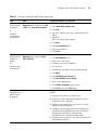
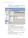
Task Table
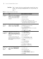
Table 9 contains the tasks you need to perform to create a service for
employee access. For a summary of configurable items, see “Step
Summary” on page 56. For detailed steps about how to perform each of
these tasks, see “Example: Configure Employee Access” on page 57.
Configure Employee Access Services
53
.
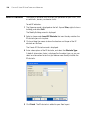
Table 9 Creating a Service for Employee Access
Task
Path
Primary Parameters to Configure
“Step
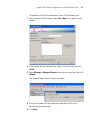
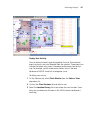
Expand the WX switch icon 1 From the Create Service Profile
Summary” on in the Organizer panel;
wizard:
page 56
right-click Service Profiles
SSID name: enter name
> Insert > Service Profile.
The Service Profile wizard is SSID type: select encrypted
displayed
Beacon: select yes (to advertise the
SSID)
2 Click Encryption tab:
Security mode: select WPA
802.1X Auth Enabled: select yes
TKIP enabled: select yes
Click Finish
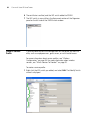
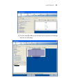
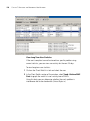
Expand the WX switch icon 1 From the Create Radio Profile
“Create a
wizard:
Radio Profile” in the Organizer panel;
right-click Radio Profiles >
on page 59
Radio profile name: enter a name
Insert > Radio Profile.
2 From the Service Profile tab:
Select the employee service profile
in the Available Service Profiles list.
Click Add; then click Finish
54
CHAPTER 3: CONFIGURING WIRELESS SERVICES
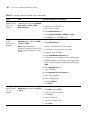
Table 9 Creating a Service for Employee Access (continued)
Task
Path
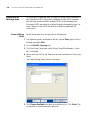
“Configure
RADIUS
Servers” on
page 61
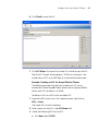
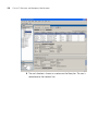
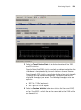
Expand the WX switch icon 1 From RADIUS Server tab:
in the Organizer panel,
Click New RADIUS server
right-click AAA > Edit;
then click RADIUS
Name: enter server name
Primary Parameters to Configure
IP Address: enter server IP address
Key: enter key
Authorization password: enter
password
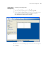
Click Next
2 From RADIUS Server Group tab:
Click New RADIUS Server Group
Name: enter a group name
Click Choose Available: select a
server
Click Finish; then click Finish again
3 Configure the AAA backend from a
RADIUS server (not in 3WXM):
Setup each WX switch as a RADIUS
client.
Define the 3Com vendor-specific
attributes (VSAs) in the RADIUS
server’s dictionary.
Configure each user record with
authorization rules (username and
password).
Configure each user with either the
Vlan-Name attribute (3Com VSA)
or the RADIUS
Tunnel-Private-Group-ID to assign
users to VLANs.
Configure authentication rules
(802.1X, MAC, last-resort, or web
authentication).
Configure Employee Access Services
55
Table 9 Creating a Service for Employee Access (continued)
Task
Path
“Specify
Network
Access Rules”
on page 64
Expand the AAA icon in the 1 From 802.1X Network Access
tab:
Organizer panel; right-click
Network Access Rules >
User Glob: enter **
Insert > 802.1X Network
Access.
SSID: enter SSID name
Primary Parameters to Configure
2 From 802.1X Policy tab:
“Set Up
VLANs on WX
Switches” on
page 66
Select Enabled
EAP type: Pass-Through
Optionally for an offload
configuration
EAP type: PEAP, EAP Sub-Protocol:
MSCHAPV2
EAP certificate: install or generate
by means of the CLI
Click Choose Available:
Select the RADIUS server group
Click Finish
Expand the WX switch icon 1 From VLAN Setup tab:
in the Organizer panel,
VLAN ID: select number
right-click VLANs > Insert >
VLAN
VLAN Name: enter name
IP Address: enter IP Address
2 From VLAN Member Selection
tab:
Available Members: select port(s);
click Add
If the port is connected to an
802.1Q trunk line, select the Tag
checkbox and change the tag value
(if necessary)
Select PVST+ (if you wish to enable
it)
3 From Spanning Tree tab:
Select STP options
4 From Spanning Tree Port Setup
tab:
Select STP port options
Click Finish
56
CHAPTER 3: CONFIGURING WIRELESS SERVICES
Step Summary
The following list summarizes the fields selected or configuration items
entered in the example that follows to configure Employee access:
1 Create a service profile.
From the Service Profile wizard, enter “Employees” as the Name of
the service profile and “Employees” as the SSID.
Select SSID Type Encrypted. Select Beacon. Select the Fall Through
Authentication as None.
Select Encryption. Select WPA for the Security Mode. Click Finish.
2 Create a radio profile.
From the Radio Profile wizard, enter “RadioProfile1” as the Name of
the radio profile.
Select Service Profile Selection. Select the Employees service profile.
Click Add. Click Finish.
3 Configure the RADIUS server in 3WXM.
From the Create Radius wizard, enter “sg1” as the Name of the
server, server’s IP address, secret for Key. Click Next.
Click New RADIUS Server Group. Enter “Group1.” Click Finish.
Click Finish.
4 Configure the RADIUS server.
Configure the RADIUS server for 802.1X. Use the recommended EAP
method, PEAP + MS-CHAPv2.
Setup each WX switch as a RADIUS client.
Define any desired 3Com vendor-specific attributes (VSAs).
Configure each user record with either the VLAN-Name attribute or
the RADIUS Tunnel-Private-Group-ID.
Configure authentication rules (802.1X, MAC, last-resort, or web
authentication.)
5 Specify network access rules.
From the 802.1X Web Network Access wizard, click the Web
Network Access tab.
For the User Glob value, enter “**”.
For the SSID, enter the SSID name.
Configure Employee Access Services
Click 802.1X Policy tab. Select Enabled. Set EAP Type to
Pass-Through.
Click Choose Available. Select the RADIUS server group.
Click Finish. Click Finish again.
57
6 Setup VLANs on the WX switches.
Example: Configure
Employee Access
From the Create VLANs wizard, click VLAN Setup. Select the VLAN ID
number. Enter the VLAN name and the IP address.
Click VLAN Member Selection tab. From Available Members, select
port(s). Click Add
Click Spanning Tree tab. Select STP options.
Click Spanning Tree Port Setup tab. Select STP port options. Click
Finish.
The following detailed steps provide an example of how to configure
Employee services. You will:
“Create a Service Profile” on page 57
“Create a Radio Profile” on page 59
“Configure RADIUS Servers” on page 61
“Specify Network Access Rules” on page 64
“Set Up VLANs on WX Switches” on page 66
In general, these same steps are required to configure other services, too.
You can refer back to this section, using the summary list or the task
table, with configuration options for “Configure Guest Access Services”
on page 69 or “Configure Voice over Wireless IP Service” on page 77.
Create a Service Profile
A service profile contains the configuration for the service you want to
offer, such as employee access, guest access, or VoWIP.
For more information about service profiles, see “Wireless
Configuration” on page 36. For more information about service sets, see
“Which Services To Provide?” on page 30.
58
CHAPTER 3: CONFIGURING WIRELESS SERVICES
To create a service profile:
1 Expand the WX switch icon in the Organizer panel, and select
Service Profiles > Insert > Service Profile.
The Create Service Profile wizard is displayed.
2 Enter the service profile and SSID names, and select SSID Type Encrypted.
3 Select Beacon (to advertise this SSID).
4 Select None for the type of Fall Through Authentication.
Authentication is generally attempted in the following order: 802.1X
authentication, MAC authentication, then fall through authentication.
For more information about authentication, see “AAA Security
Configuration” on page 38.
5 Click Next. The Encryption wizard is displayed.
Configure Employee Access Services
59
6 Click next to WPA to enable it.
The 802.1X Auth Enabled and TKIP Enabled options are automatically
selected when you enable WPA.
7 Click Finish.
The service profile Employees is displayed in the Organizer panel.
Create a Radio Profile
You configure a radio profile to set attributes that you can apply to
multiple radios. Rather than configuring each radio individually, the radio
profile is applied to multiple radios that you select. Service profiles are
mapped to radio profiles.
The radio profile can contain RF Auto-Tuning settings and IEEE 802.11
settings that control how the data is received and transmitted.
60
CHAPTER 3: CONFIGURING WIRELESS SERVICES
MAPs (and consequently, radios) need to be added to 3WXM after
creating a radio profile. For more information about adding radios, refer
to one of the following:
“Using RF Auto-Tuning” on page 91
“Using RF Auto-Tuning with Modelling” on page 99
“Using RF Planning” on page 113
To create a radio profile and map a service profile to it:
1 Expand the WX switch in the tree topology to which you want to add a
radio profile.
2 Right-click Radio Profiles > Insert.
The Create Radio Profiles wizard is displayed.
3 From the Radio Profile tab, enter the name of the radio profile. Click
Service Profile Selection at the top of the wizard.
4 Select the employee service profile in the Available Service Profiles list.
Click Add.
Configure Employee Access Services
61
5 Click Finish to save the changes and close the wizard.
Configure RADIUS Servers
Remote Authentication Dial-In User Service (RADIUS) is a client-server
security protocol that provides authentication, authorization, and
accounting for network users and devices. A RADIUS server stores user
profiles, which include usernames, passwords, and other user attributes.
To configure RADIUS servers, you must:
Configure RADIUS server attributes in 3WXM
Configure attributes on the RADIUS server
Configure RADIUS Server in 3WXM To configure RADIUS in 3WXM,
you define RADIUS server groups (named sets of RADIUS servers). You
must create at least one server group. RADIUS server groups can
authenticate administrators and network users.
62
CHAPTER 3: CONFIGURING WIRELESS SERVICES
To configure the RADIUS server in 3WXM:
1 Expand the WX switch icon in the Organizer panel, right-click on AAA,
and select Edit.
The Modify AAA wizard is displayed.
2 Click RADIUS to display the Modify RADIUS wizard, and click Next.
The Create RADIUS Server wizard is displayed.
3 Type the name, IP address, key, and authorization password for the
server; then click Finish.
4 Click Next to display the RADIUS Server Group page.
5 Click New RADIUS Server Group.
6 Type a name for the group, then click Choose Available and select the
server from the dropdown list.
7 Click Finish to close the Create RADIUS Server Group page.
8 Click Finish again to redisplay the Modify AAA wizard.
Configure Employee Access Services
63
Configure Attributes on the RADIUS Server To authenticate users,
you will need to configure users either in the local database or on RADIUS
servers. To configure services for Employee access, the following items
should be configured on the RADIUS server.
To configure the RADIUS server:
1 Configure RADIUS server to perform 802.1X using the recommended
EAP method PEAP + MS ChapV2.
2 Setup each WX switch as a RADIUS client.
3 Define any desired 3Com vendor-specific attributes (VSAs) in the RADIUS
server’s dictionary.
The vendor-specific attributes (VSAs) created by 3Com are embedded
according to the procedure recommended in RFC 2865, with Vendor-ID
set to 14525. Table 10 describes the 3Com VSAs, listed in order by
vendor type number.
Table 10 3Com VSAs
Attribute
Type,
Vendor
ID,
Vendor
Type
Rcv in
Access
Resp?
Sent in
Access
Reqst?
Sent in
Acct
Reqst?
Description
VLAN-Name
26,
43,
2
Yes
No
Yes
Name of the VLAN to which the client belongs.
Mobility-Profile
26,
43,
3
Yes
No
No
Name of the Mobility Profile used by the authorized
client.
Encryption-Type
26,
43,
4
Yes
No
No
Type of encryption used to authenticate the client.
Time-Of-Day
26,
43,
5
Yes
No
No
Day(s) and time(s) during which a user can log into
the network.
SSID
26,
43,
6
Yes
No
Yes
Name of the SSID you want the user to use. The
SSID must be configured in a service profile, and the
service profile must be used by a radio profile
assigned to 3Com radios in the Mobility Domain.
64
CHAPTER 3: CONFIGURING WIRELESS SERVICES
Table 10 3Com VSAs (continued)
Attribute
End-Date
Type,
Vendor
ID,
Vendor
Type
26,
43,
7
Rcv in
Access
Resp?
Sent in
Access
Reqst?
Sent in
Acct
Reqst?
Yes
No
No
Description
Date and time after which the user is no longer
allowed to be on the network. Use the following
format:
YY/MM/DD-HH:MM
Start-Date
URL
26,
43,
8
Yes
26,
43,
9
Yes
No
No
Date and time at which the user becomes eligible to
access the network. Use the following format:
YY/MM/DD-HH:MM
No
No
URL to which the user is redirected after successful
Web authentication. Use the following format:
http://www.example.com
4 Configure each user record with authorization rules (username and
password) and with either the Vlan-Name attribute (3Com VSA) or the
RADIUS Tunnel-Private-Group-ID to assign users to VLANs.
Other attributes are optional.
Specify Network Access Rules
To specify network access rules:
1 Expand the AAA icon in the Organizer panel; right-click Network Access
Rules > Insert > 802.1X Network Access.
2 Enter ** as a wildcard in the Matching User Glob field.
“**” is a reserved keyword that matches on all user names.
3 Enter any as a wildcard in the SSID field.
“Any” is a reserved keyword that matches on all SSID names. Click Next.
Configure Employee Access Services
65
4 From the 802.1X Policy tab, select Enabled and Pass-Through as the
EAP Type.
This option uses the RADIUS servers to perform all the EAP and AAA
processing. An EAP certificate does not need to be installed on the WX
switch.
5 Click Finish.
You can also create an offload configuration. An offload configuration
allows a WX switch to offload some of the work from the RADIUS
servers. The WX switch will perform EAP processing on behalf of the
RADIUS servers. If you use an offload option, you will need to use the CLI
to generate or install an EAP certificate on the WX switch. To specify an
offload configuration, select PEAP as the EAP Type, and MSCHAPV2 as
the EAP Sub-Protocol.
66
CHAPTER 3: CONFIGURING WIRELESS SERVICES
6 Click Choose Available and select the RADIUS server group from the
dropdown list.
7 Click Finish to close the Modify AAA wizard.
Set Up VLANs on WX Switches
WX switches in a Mobility Domain contain a user’s traffic within the
VLAN the user is assigned to. For example, if you assign a user to VLAN
red, the WX switches in the Mobility Domain contain the user’s traffic
within VLAN red configured on the switches. The VLANs you set up for
service sets support wireless users—they don’t serve as management
VLANs.
If an WX is connected to the network by only one IP subnet, the WX must
have at least one VLAN configured. Optionally, each VLAN can have its
own IP address. However, no two IP addresses on the switch can belong
to the same IP subnet. User VLANs must be defined on at least on WX
switch within the Mobility Domain.
Configure Employee Access Services
67
You can configure the Spanning Tree Protocol (STP) on a VLAN. STP is
used to maintain a loop-free network; meaning, devices will recognize a
loop in the topology and block one or more redundant paths, creating a
loop-free path.
The Mobility System Software (MSS) supports Per-VLAN Spanning Tree
protocol (PVST+). PVST+ allows a separate spanning tree in each VLAN.
STP, disabled by default on all VLANS, is configurable for individual
VLANs. STP does not run on MAP ports or wired authentication ports and
does not affect traffic flow on these port types.
To set up a VLAN on a WX switch:
1 Expand the WX switch icon in the Organizer panel, right-click on VLANs >
Insert > VLAN.
The Create VLAN wizard is displayed.
2 Select the VLAN ID number and enter the VLAN Name.
3 (Optional) To assign an IP interface to the VLAN, type the IP address or
select DHCP Client.
68
CHAPTER 3: CONFIGURING WIRELESS SERVICES
4 Click Next. The VLAN Member Selection page is displayed.
5 From the Available Members pane, select the network ports that will be
used to reach the router interface and click Add.
If the network port is an 802.1Q tagged trunk link, select the Tag
checkbox for the port or port group. By default, the checkbox is not
selected.
To remove a tag for a port or port. Double-click the Tag Value column
for the port or port group. Change the tag value.
If you specify a tag value, 3Com recommends that you use the same
value as the VLAN number. 3Com wireless switches do not require the
VLAN number and tag value to be the same, but other devices may do so.
6 (Optional) If you want to add STP to a VLAN, select the Spanning Tree
tab and set options.
7 (Optional) For STP, select the Spanning Tree Port Setup tab and set
options.
What’s Next?
After you create Employee services, you can create additional services.
For information about configuring additional services, refer to:
“Configure Guest Access Services” on page 69
“Configure Voice over Wireless IP Service” on page 77
After you have created additional services, you can create your RF
environment, and deploy your configuration and enable monitoring.
For information about creating your RF environment, refer to:
“Using RF Auto-Tuning” on page 91
“Using RF Auto-Tuning with Modelling” on page 99
“Using RF Planning” on page 113
For information about deploying your configuration and enabling
monitoring your network, refer to:
“Managing and Monitoring Your Network” on page 143.
Configure Guest Access Services
Configure Guest
Access Services
69
Guest access is access for visitors at your location and is typically clear (no
encryption).
This section contains the following information about how to configure
Guest access services:
“Task Table” on page 70
“Step Summary” on page 71
“Optional: Configure Mobility Profiles” on page 73
Table 11 on page 70 contains the tasks you must perform to configure
Guest access services.
The “Step Summary” provides the configurable options you should set.
The table contains references to the section “Example: Configure
Employee Access” on page 57. The references are provided in case you
want to refer back to detailed steps. However, be sure to use the
configurable options for Guest access services set forth in the “Step
Summary” on page 71.
Also, you can optionally configure mobility profiles for your Guest access
services to limit access based on criteria, such as RF coverage area or time
of day.
70
CHAPTER 3: CONFIGURING WIRELESS SERVICES
Task Table
Table 11 contains the tasks you need to perform to create Guest access
services. For a summary of configurable items, see “Step Summary” on
page 71.
Table 11 Creating a Service for Guest Access
Task
Path
“Step Summary” Expand the WX switch icon in the
on page 56
Organizer panel; right-click Service
Profiles > Insert > Service Profile.
The Create Service Profile wizard is
displayed.
“Create a Radio
Profile” on
page 59
Expand the WX switch icon in the
Organizer panel; right-click Radio
Profiles > Insert > Radio Profile.
Primary Parameters to Configure
1 From the Create Service Profiles wizard:
Name: enter Guests
SSID: enter Guests
SSID type: select clear
Beacon: select yes (to advertise the SSID)
Fall Through Auth: Web Portal or Last Resort (to
allow guest access without authentication)
1 From Create Radio Profiles wizard:
Radio profile name: enter a name
2 From Service Profile tab:
“Configure Local Expand the WX switch icon in the
Authentication” Organizer panel, right-click > AAA >
Edit; click Local User Database. The
on page 74
Modify Local User Database wizard is
displayed.
Select the Guest service profile in the Available
Service Profiles list.
Click Add; then click Finish
1 Click User Group tab
Select New > User Group
Enter: User group name
Enter: VLAN name
Configuring authentication can be
2 Click Choose Available or New
done more easily by first adding a user
group and associating or creating users Create a new user or select a user
for that group.
Click Next
Click User Attributes:
3 Select User Attributes
Click Finish; click Finish again.
4 Repeat steps 1 – 3 for all Guests.
“Specify
Network Access
Rules” on
page 64
Expand the AAA icon in the Organizer
panel; right-click Network Access
Rules > Insert > Web Network
Access.
1 From Web Network Access tab:
User Glob: enter **
SSID: enter SSID name
From Authentication tab:
Select Choose Available > Local server
Click Finish
Configure Guest Access Services
71
Table 11 Creating a Service for Guest Access
Task
Path
Primary Parameters to Configure
“Set Up VLANs
on WX
Switches” on
page 66
Expand the WX switch icon in the
Organizer panel, right-click VLANs >
Insert > VLAN
Setup guest VLAN on an WX switch that can access the
external DMZ subnet.
1 From VLAN Setup tab:
VLAN ID: select number (must be unique)
VLAN Name: enter name (must be unique)
IP Address: enter IP Address
2 From VLAN Member Selection tab:
Available Members: select port(s) that connect to the
DMZ; click Add
3 From Spanning Tree tab:
Select STP options
4 From Spanning Tree Port Setup tab:
“Optional:
Configure
Mobility Profiles”
on page 73
Expand the WX switch icon in the
Organizer panel, right-click on a WX
switch; select Edit. Click AAA >
Mobility Profile.
Step Summary
Select STP port options
Click Finish
1 Click New Mobility Profile:
Enter a Profile Name
Enter: selected
Select the Ports or Distributed MAPs
Click Finish
The following list summarizes the fields selected or configuration items
entered configure Guest access.
1 Create a service profile.
From the Service Profile wizard, enter “GuestsSrvcProf” as the Name
of the service profile and “Guests” as the SSID.
Select SSID Type Clear. Select Beacon. Select the Fall Through
Authentication as “Web Portal”.
2 Create a radio profile.
From the Radio Profile wizard, enter the name of the radio profile.
Select Service Profile Selection. Select the Guests service profile.
Click Add. Click Finish.
72
CHAPTER 3: CONFIGURING WIRELESS SERVICES
3 Configure local authentication.
From the Local User Database wizard, click User Group. Select
New > User Group, and enter a group name and a VLAN name.
Add users to the group. Click Choose Available or New to add
users. Click Next.
Click User Attributes. Select User Attributes. Click Finish.
Although normally, setting the VLAN is required, the special web-portal
user that MSS creates for WebAAA assigns the VLAN instead. Setting the
VLAN for an individual WebAAA user has no effect.
4 Modify the VLAN assigned to the special user “web-portal-Guests”,
which MSS created when you created the “Guests” SSID with Fall
Through Authentication “Web Portal”. Change the VLAN from default to
the VLAN you assigned to the WebAAA users.
From the Local User Database wizard, click Users. Select
“web-portal-Guests”, and click Modify.
Edit the name in the VLAN Name box. Click Finish.
5 Specify network access rules.
From the Web Network Access wizard, click the Web Network
Access tab. For the User Glob value, enter “**”.
For the SSID, enter the SSID name.
Click Authentication. Select Choose Available > Local server.
6 Set up VLANs on the WX switches.
From the Create VLANs wizard, click VLAN Setup. Select the VLAN ID
number. Enter the VLAN name and the IP address.
Click VLAN Member Selection tab. From Available Members, select
port(s). Click Add
Click Spanning Tree tab. Select STP options.
Click Spanning Tree Port Setup tab. Select STP port options. Click Finish.
7 Optional: Configure a Mobility Profile.
From New Mobility Profile wizard, enter the Profile Name.
Select “Selected.”
Choose the Ports or Distributed MAPs to which you’ll restrict guest
users to certain geographic areas of your network.
Click Finish.
Configure Guest Access Services
73
For detailed information about the steps, see the cross-references in the
“Task Table” on page 70. New configuration items that were not part of
the example “Configure Employee Access Services” on page 52 are
included in the following sections.
Optional: Configure
Mobility Profiles
Mobility Profile™ attributes allow or deny access to the network for a
specific user or group of users. When you create a Mobility Profile, you
specify which MAP ports, Distributed MAPs, or wired authentication ports
are to be included. Typically, you include ports that are defined as MAP
ports or Distributed MAPs. You can specify that all or no ports are
included, or you can specify a list of ports to be included.
When you apply the Mobility Profile, it guests have access only through
specific areas of your WLAN—if they roam outside of a designated area
supported by an WX switch or certain MAPs, they no longer have access
to the Internet.
After creating a Mobility Profile, you can assign it to users created in the
local WX user database, or users who are authenticated and authorized
by a RADIUS server. To assign it to users in the WX user database, you
add the Mobility Profile name when you create or modify a user or user
group. To add this on a RADIUS server, you assign the name of the
Mobility Profile by using the Mobility-Profile RADIUS attribute, which is a
3Com vendor-specific attribute (VSA).
To create a Mobility Profile:
1 Right-click on a WX switch in the Organizer panel. Select Edit.
2 Select AAA at the top of the wizard, if not already selected.
3 Select Mobility Profile from the organizer list on the left side of the
page, if not already selected.
4 Click New Mobility Profile.
The Create Mobility Profile wizard appears.
5 In the Profile Name box, type the name of the Mobility Profile.
The name can be up to 16 alphanumeric characters, and it cannot
contain tabs.
The Mobility Profile Name has to be defined as an authorization attribute
in the defined users or user groups in the local database.
6 In the Ports list, specify ports to include in the Mobility Profile:
74
CHAPTER 3: CONFIGURING WIRELESS SERVICES
All—Include all MAP or wired authentication ports. Go to step 13.
Selected—Include a selected list of ports. Go to the next step.
None—Include no ports. Go to step 13.
7 Click Choose Available. The Physical Port Selection dialog box appears.
8 Select the ports to be included in the Mobility Profile. To make multiple
selections. press Shift (for contiguous items) or Control (for
noncontiguous items) while clicking items.
9 In the Distributed MAPs list, specify the Distributed MAPs to include in
the Mobility Profile:
All—Include all Distributed MAPs. Go to step 13.
Selected—Include a selected list of Distributed MAPs. Go to the
next step.
None—Include no Distributed MAPs. Go to step 13.
10 Click Choose Available.
11 Select the Distributed MAPs to be included in the Mobility Profile.
12 Click Close. The Create Mobility Profiles dialog box is active.
13 Click Finish to save the changes and close the wizard.
Configure Local
Authentication
The WX switch contains a local database that can store user information
for a 3Com WLAN. You can use the local database to create users and
authenticate them, or you can use the local database in conjunction with
a RADIUS server. For example, although you might use a RADIUS server
to manage most users, you could define IT staff as users in the local
database in the event that the RADIUS server is unavailable.
You can create two types of users in the local database:
Named users—These users are authenticated by username and
password and are assigned to specific VLANs. Users include
administrators and network users. You can group these users by
creating user groups, in order to simplify configuration.
Configure Guest Access Services
75
MAC address users—These users are authenticated by a MAC
address. For example, devices such as PDAs or cellular phones that do
not support 802.1X authentication are identified when the WX switch
discovers the MAC addresses of these devices from received frames.
The MAC address is the username and is authenticated by the local
database. You can group these users by creating user groups. MAC
address users and user groups cannot be assigned administrative
access to the WX switch.
To create a user group and named Guest users:
1 Expand the WX switch icon in the Organizer panel, right-click on
AAA > Edit. Click Local User Database.
The Modify Local Database User wizard is displayed.
2 Click User Group. Enter the Name for the user group. Click New.
Also specify the VLAN name, unless the group is for WebAAA users.
If the group is for WebAAA users, do not specify the VLAN name. The
VLAN name is instead associated with the special web-portal user that
MSS creates for WebAAA assigns the VLAN. Setting the VLAN for an
individual WebAAA user or user group has no effect.
The Create User Group wizard is displayed.
76
CHAPTER 3: CONFIGURING WIRELESS SERVICES
3 Click Choose Available to select users to add to the user group, or click
Create to create new users.
4 Enter the user’s Name and user’s Password. Select the User Group to
which the user belongs. Click Next.
The Create User wizard is displayed.
5 Select any User Attributes you would like applied to the user.
6 Click Finish.
What’s Next?
After you create Guest services, you can create another service.
For information about configuring an additional service, refer to:
“Configure Voice over Wireless IP Service” on page 77
You can create your RF environment, and deploy your configuration and
enable monitoring.
For information about creating your RF environment, refer to:
“Using RF Auto-Tuning” on page 91
“Using RF Auto-Tuning with Modelling” on page 99
“Using RF Planning” on page 113
Configure Voice over Wireless IP Service
77
For information about deploying your configuration and enabling
monitoring your network, refer to:
Configure Voice
over Wireless IP
Service
“Managing and Monitoring Your Network” on page 143.
Voice over Wireless IP (VoWIP) is a new technology, merging VoIP (Voice
over IP) with 802.11 wireless LANs to create a wireless telephone system.
Organizations that add VoWIP to their wireless LANs can deploy and
manage voice and data over a single wireless backbone, reserving some
portion of network bandwidth to support real-time voice
communications.
For a Voice over Wireless IP (VoWIP) service (sometimes also referred to
simply as VoIP, or Voice over IP), you can configure either local or RADIUS
server authentication, and add Access Lists (ACLs) to restrict user access.
This section contains the following information about how to configure
VoWIP services:
“Task Table” on page 78
“Step Summary” on page 81
“Configure Local Authentication” on page 82
“Configure Access Control Lists” on page 84
Table 12 on page 78 contains the tasks you must perform to configure
Guest access services. The table contains references to the section
“Example: Configure Employee Access” on page 57. The references are
provided in case you want to refer back to detailed steps. However, be
sure to use the configurable options for VoWIP access services set forth in
the “Step Summary” on page 81. The “Step Summary” provides the
configurable options you should set.
78
CHAPTER 3: CONFIGURING WIRELESS SERVICES
Task Table
Table 12 contains the tasks you need to perform to create VoWIP access
services. For a summary of configurable items, see “Step Summary” on
page 81.
Table 12 Creating a Service for VoWIP Access
Task
Path
“Step Summary” Expand the WX switch icon in the
on page 56
Organizer panel; right-click Service
Profiles > Insert > Service Profile
Primary Parameters to Configure
1 From Service Profile tab:
SSID name: enter name
SSID type: select Encrypted
Beacon: not selected (hide presence of SSID for
marginally improved security)
Fall Through Auth: None
2 From Encryption tab:
Security mode: select WEP or WPA/PSK (provides higher
level of security)
3 If you select WEP:
802.1X Auth Enabled: select yes
TKIP enabled: select no
Click Finish
4 If you select WPA/PSK (Must be supported by your
VoWIP device):
“Create a Radio
Profile” on
page 59
Expand the WX switch icon in the
Organizer panel; right-click Radio
Profiles > Insert > Radio Profile
802.1X Auth Enabled: select no
PSK Auth: select enabled
Pre-shared Key: (64 Hex characters) or enter a pass
phrase and click Generate Key
TKIP enabled: select yes
Click Finish
1 From Radio Profile tab:
Radio profile name: enter a name
2 From Service Profile tab:
Select the VoWIP service profile in the Available Service
Profiles list.
Click Add; then click Finish
Configure Voice over Wireless IP Service
79
Table 12 Creating a Service for VoWIP Access (continued)
Task
Path
“Configure Local Expand the WX switch icon in the
Authentication” Organizer panel, right-click > AAA
on page 82
> Edit; click Local User Database
or
Configure
authentication
using RADIUS
Primary Parameters to Configure
1 Click User:
Select New MAC Address User
2 Click User:
User MAC Address: enter user’s VoWIP device MAC
address
(Optional)
MAC User Group: select a group
Click Next
3 From User Attributes tab:
Select User Attributes
Click Finish
“Configure
Expand the WX switch icon in the
RADIUS Server in Organizer panel, right-click AAA >
3WXM” on
Edit > RADIUS
page 61
1 From RADIUS Server tab:
or
Configure local
authentication
Click New RADIUS server
Name: enter server name
IP Address: enter server IP address
Key: enter key
Authorization password: enter password (required)
Click Next
2 From RADIUS Server Group tab:
“Configure
N/A
Attributes on the
RADIUS Server”
on page 63
Click New RADIUS Server Group
Name: enter a group name
Click Choose Available: select a server
Click Finish; then click Finish again
Configure the AAA backend from a RADIUS server (not in
3WXM):
1 Setup each WX switch as a RADIUS client.
2 Define the 3Com vendor-specific attributes (VSAs) in
the RADIUS server’s dictionary.
3 Configure user record, where user name is the MAC
address (entered with dashes)
4 Configure user password, where the password is the
authorization password defined in your WX RADIUS
configuration (with dashes), and password
authorization rules (username and password)
5 Configure each user with the Vlan-Name attribute and
other optional attributes
80
CHAPTER 3: CONFIGURING WIRELESS SERVICES
Table 12 Creating a Service for VoWIP Access (continued)
Task
Path
“Specify
Network Access
Rules” on
page 64
1 From MAC Network Access page:
Expand the AAA icon in the
Organizer panel; right-click Network
Access Rules > Insert > MAC
Matching user Glob: enter **
Network Access
SSID: enter SSID name
Primary Parameters to Configure
2 From Authentication tab:
“Set Up VLANs
on WX
Switches” on
page 66
Expand the WX switch icon in the
Organizer panel, right-click VLANs
> Insert > VLAN
Note: 3Com recommends
completely isolating the VoWIP VLAN
as a best practice procedure in your
WLAN.
Select Choose Available > RADIUS or Local
Click Finish; then click Finish again
Setup VoWIP VLAN.
1 From VLAN Setup tab:
VLAN ID: select number (must be unique)
VLAN Name: enter name (must be unique)
IP Address: enter IP Address
2 From VLAN Member Selection tab:
VLAN Name: enter VLAN name for the VoWIP phones
Available Members: select port(s) to reach other ports
on the VoWIP VLAN or the VoWIP gateway/PBX; click
Add
3 From Spanning Tree tab:
Select STP options
4 From Spanning Tree Port Setup tab:
Select STP port options
5 From VLAN IGMP tab:
“Configure
Access Control
Lists” on
page 84
Uncheck Enabled
Click Finish
1 From ACL Setup tab:
Expand the WX switch icon in the
Organizer panel, right-click on ACLs
Click New; select an ACE
> Insert
Enter ACE set up information
Click Finish
2 From ACL Map tab:
Map ACL to VoWIP VLAN
Click Finish
Configure Voice over Wireless IP Service
Step Summary
81
The following list summarizes the fields selected or configuration items
entered in the example that follows to configure VoWIP access:
1 Create a service profile.
From the Service Profile wizard, enter “VoWIP” as the Name of the
service profile and “VoWIP” as the SSID.
Select SSID Type Encrypted. Do not select Beacon. Select the Fall
Through Authentication as None.
Select Encryption. Select WEP or WPA/PSK for the Security Mode,
and click Finish.
WEP—802.1X Auth Enabled is yes, TKIP Enabled is no.
WPA/PSK—802.1X Auth Enabled is no, PSK Auth is enabled TKIP
Enabled is yes. Enter a 64 Hex character key for Preshared key, or
enter a pass phrase and click Generate Key.
2 Create a radio profile.
From the Radio Profile wizard, enter “VoWIP1” as the Name of the
radio profile.
Select Service Profile Selection. Select the VoWIP service profile. Click
Add. Click Finish.
3 Configure local authentication (or configure the RADIUS server in
3WXM).
From the Local Database User wizard, click User.
Select New MAC Address User. Click User. Enter user’s VoWIP device
MAC address. Click Next.
From Attributes tab, select User Attributes. Click Finish.
4 Create a new MAC Network Access rule.
For the User Glob value, enter “**”.
For the SSID, enter VoWIP.
From Authentication tab, select Choose Available > Local.
Click Finish. Click Finish again.
5 Setup VLANs on the WX switches.
From the Create VLANs wizard, click VLAN Setup. Select the VLAN ID
number (must be unique). Enter the VLAN name and the IP address.
82
CHAPTER 3: CONFIGURING WIRELESS SERVICES
Click VLAN Member Selection tab. From Available Members, select
the VLAN name for the VoWIP phones.
Select port(s) to reach other ports on the VoWIP VLAN or the VoWIP
gateway/PBX. Click Add.
Click Spanning Tree tab. Select STP options.
Click Spanning Tree Port Setup tab. Select STP port options.
Click VLAN IGMP tab. Uncheck enabled.
Click Finish.
6 Create ACLs.
From the Create ACL wizard, enter a name for the ACL. The example
uses “svp” for SpectraLink or “voice” for Avaya).
Add ACEs to the ACL.
Configure Local
Authentication
See “Example: Creating an ACL for SpectraLink Wireless Phones”
on page 85 for ACE details.
See “Example: Creating an ACL for Avaya Wireless Phones” on
page 87 for ACE details.
Click Finish.
The WX switch contains a local database that can store user information
for a 3Com WLAN. You can use the local database to create users and
authenticate them, or you can use the local database in conjunction with
a RADIUS server. For example, although you might use a RADIUS server
to manage most users, you could define IT staff as users in the local
database in the event that the RADIUS server is unavailable.
You can create two types of users in the local database:
Named users—These users are authenticated by username and
password and are assigned to specific VLANs. Users include
administrators and network users. You can group these users by
creating user groups, in order to simplify configuration.
Configure Voice over Wireless IP Service
83
MAC address users—These users are authenticated by a MAC
address. For example, devices such as PDAs or cellular phones that do
not support 802.1X authentication are identified when the WX switch
discovers the MAC addresses of these devices from received frames.
The MAC address is the username and is authenticated by the local
database. You can group these users by creating user groups. MAC
address users and user groups cannot be assigned administrative
access to the WX switch.
To create MAC users
1 Expand the WX switch icon in the Organizer panel, right-click on AAA >
Edit.
2 Click Local User Database.
3 Click New. Select New MAC Address User. The Create User wizard
appears.
4 Enter the User MAC Address and the VLAN Name to which the user
belongs.
You can also specify that the user be part of a MAC User Group. Click
Next.
5 Select any User Attributes you would like applied to the user.
6 Click Finish.
84
CHAPTER 3: CONFIGURING WIRELESS SERVICES
Configure Access
Control Lists
You can control access using security access control lists (ACLs). Security
ACLs permit or deny traffic based on IP protocol, IP addresses and,
optionally, TCP or UDP port. They also can be used to set type-of-service
(TOS) and class-of-service (CoS) values in a packet.
Suggested uses for ACLs include restricting guest access from your
intranet, or restricting guests from communicating with each other (using
an IP access control entry).
You create an ACL by defining a series of access control entries (ACEs).
ACEs are processed in the order in which they are added to the ACL.
Generally, more specific checks are performed before general checks.
Because of this, the order of the ACE is important within the ACL.
You can add the following types of ACEs to an ACL:
IP—Filters packets by source and destination IP addresses, type of
TOS, or precedence.
TCP—Filters packets by established TCP connections, source and
destination IP addresses, TOS, precedence, or TCP source and
destination ports.
ICMP—Filters packets by source and destination IP addresses, TOS,
precedence, ICMP type, or ICMP code.
UDP—Filters packets by source and destination IP addresses, TOS,
precedence, or UDP source and destination ports.
Layer 4 Protocol—Filters packets by source and destination IP
addresses, TOS, precedence, or Layer 4 protocol.
After creating an ACL, you can assign it to users created in the local WX
user database or users who are authenticated and authorized by a
RADIUS server. You assign the name of the ACL by using the Filter-Id.in
and Filter-Id.out RADIUS attributes. Assign the Filter-Id.in RADIUS
attribute with the name of an ACL that filters incoming packets. Assign
the Filter-Id.out RADIUS attribute with the name of an ACL that filters
outgoing packets. The ACL name must have an .in or .out suffix.
Configure Voice over Wireless IP Service
85
Example: Creating an ACL for SpectraLink Wireless Phones
The following example illustrates how to define an ACL on a WX switch
in an environment where SpectraLink® wireless phones are used.
To define an ACL on a WX switch and add ACEs:
1 Expand the WX switch icon in the Organizer panel; right-click on
ACLs > Insert > ACL. The Create ACL wizard is displayed.
2 Enter the name for the ACL in the ACL Name field.
3 Click New. Select New L4 Protocol ACE. Create an ACE that matches
the SVP protocol (SpectraLink’s proprietary protocol).
Select 7 for the CoS value to map the ACL to an elevated priority.
If Wi-Fi Multimedia (WMM) support is disabled, use 6 or 7 for SVP, and
use 4 or 5 for other VoWIP types. When WMM is disabled, the MAP
forwarding queue that maps to CoS values 6 and 7 is optimized for SVP.
If WMM support is disabled, use 6 or 7 for all types of VoWIP.
Select 119 for the Protocol ID value (representing the SVP protocol).
Click Finish. The Create ACL wizard is displayed again.
86
CHAPTER 3: CONFIGURING WIRELESS SERVICES
4 Click New. Select IP ACE. Create a second ACE as a “catch-all” ACE,
permitting other traffic to pass at a normal priority through the WLAN.
5 Click Finish.
The Create ACL wizard is displayed again with the two ACEs displayed.
Configure Voice over Wireless IP Service
87
6 Click Finish to save the ACL.
7 Click ACL Map at the top of the Create ACL wizard to map the ACL.
Map the ACL to ports (or port groups), VLANs, or virtual ports. You
cannot map an ACL to an MAP port or a wired authentication port.
Example: Creating an ACL for Avaya Wireless Phones
The following example illustrates how to define an ACL for an
environment where Avaya® wireless phones are using Avaya Media
Servers and Call Controllers in a WLAN.
To define an ACL on a WX switch and add ACEs:
1 Expand the WX switch icon in the Organizer panel; right-click on
ACLs > Insert.
The Create ACL wizard is displayed.
2 Enter a name for the ACL in the ACL Name field.
3 Create the following ACEs for the ACL.
a Click New. Select IP ACE.
88
CHAPTER 3: CONFIGURING WIRELESS SERVICES
This ACE (as well as the next one) matches the DiffServ codepoints
that Avaya equipment uses for call setup and call control traffic.
Select 7 for the CoS value to map the ACL to an elevated priority.
If Wi-Fi Multimedia (WMM) support is disabled, use 6 or 7 for SVP, and
use 4 or 5 for other VoWIP types. When WMM is disabled, the MAP
forwarding queue that maps to CoS values 6 and 7 is optimized for SVP.
If WMM support is disabled, use 6 or 7 for all types of VoWIP.
Select 4 for the Precedence value. This value specifies that packets
with flash override precedence are filtered.
Select 4 for the type of service (TOS) value.
Click Finish.
b Click New. Select IP ACE.
Select 7 for the CoS value to map the ACL to an elevated priority.
Select 5 for the Precedence value. This value specifies that packets
with critical precedence are filtered.
Select 12 for the TOS value.
Click Finish.
c Click New. Select UDP Ace.
This ACE roughly matches the RTP protocol used by Avaya IP
Softphones for voice traffic.
Select 7 for the CoS value to map the ACL to an elevated priority.
Select Range for the Source Port and specify a range. The range in
the example is 2048 to 65535.
Click Finish
Configure Voice over Wireless IP Service
89
d Click New. Select New IP ACE.
This ACE is a generic “catch-all,” permitting other traffic to pass at a
normal priority through the WLAN.
Click Finish.
4 The ACL properties are displayed.
5 Click Finish to save the ACL.
6 Map the ACL to ports (or port groups), VLANs, or virtual ports. Click ACL
Map at the top of the Create ACL wizard to map the ACL.
You cannot map an ACL to a MAP port or a wired authentication port.
90
CHAPTER 3: CONFIGURING WIRELESS SERVICES
What’s Next?
After you create VoWIP access services, you can create another service.
For information about configuring an additional service, refer to:
“Configure Guest Access Services” on page 69
You can create your RF environment, and deploy your configuration and
enable monitoring.
For information about creating your RF environment, refer to:
“Using RF Auto-Tuning” on page 91
“Using RF Auto-Tuning with Modelling” on page 99
“Using RF Planning” on page 113
For information about deploying your configuration and enabling
monitoring your network, refer to:
“Managing and Monitoring Your Network” on page 143.
4
Overview
USING RF AUTO-TUNING
RF Auto-Tuning is a technique you can use to configure your RF (radio)
network. RF Auto-Tuning is a quick method that requires minimal
configuration and no RF planning or site surveys, and instead, relies on
the AutoTune feature to set MAP channels and power settings.
This is a great way to quickly install a WX switch and MAPs, and observe
how the network operates. The RF Auto-Tuning technique is best suited
to networks containing fewer MAPs.
To learn more about the benefits of RF Auto-Tuning, see “RF
Auto-Tuning” on page 32.
To use this technique:
1 Physically place your equipment (WX switches and MAPs) in their desired
locations.
2 Configure initial WX switch connectivity (configure IP addresses and
install certificates).
3 Upload the WX switch configuration into a 3WXM network plan.
4 Create a service profile.
5 Create a radio profile (or use the default radio profile).
6 Map your service profile to your radio profile.
7 Create your MAPs.
8 Apply a radio profile to each radio on a MAP.
9 Deploy your configuration.
92
CHAPTER 4: USING RF AUTO-TUNING
Place Your
Equipment
You will need to unpack and physically install your WX switches and
MAPs. For information about installing your equipment, see “Equipment
Installation” on page 42.
Configure Initial
WX Switch
Connectivity
After installing a WX switch, you must use the command-line interface
(CLI) to prepare it for configuration and management by 3WXM. Use the
Web Quick Start (if available), or enter the quickstart command at the
CLI prompt. From there, you will:
Configure IP connectivity between the WX and 3WXM.
Enable secure communication between the WX and 3WXM or the
Web browser by installing certificates from a certificate authority (CA)
or a self-generated certificate.
For more information about configuring initial WX switch connectivity,
see the Wireless LAN Switch and Controller Installation and Basic
Configuration Guide.
Upload the WX
Switch
Configuration into
a 3WXM Network
Plan
Retrieve the basic configuration information you added to the WX switch
and upload it into 3WXM.
Upload the WX Switch Configuration into a 3WXM Network Plan
93
To upload the WX switch configuration into a 3WXN network plan:
1 From the main 3WXM window, select File > New. The Options wizard
appears.
2 Enter a name for your network plan, select a Country Code, and click
Finish.
3 Select Manage > Managed Devices from the main menu bar; then click
Upload.
The Upload Wireless Switch wizard is displayed.
4 Enter the IP address and the enable password for the WX switch
containing the configuration.
5 Click Next.
94
CHAPTER 4: USING RF AUTO-TUNING
6 The certificate is verified, and the WX switch added to 3WXM.
7 The WX switch is now visible in the Equipment section of the Organizer
panel on the left side of the 3WXM main window.
Create a Service
Profile
A service profile contains the configuration for the service you want to
offer, such as employee access, guest access, or multi-hosted access.
For more information about service profiles, see “Wireless
Configuration” on page 36. For more information about wireless
services, see “Which Services To Provide?” on page 30.
To create a service profile:
1 Right-click the WX switch you added, and select Edit. The Modify Switch
wizard is displayed.
Create a Radio Profile and Map the Service Profile to It
95
2 Click Wireless. Click Service Profile and select New Service Profile.
3 Enter the name and SSID for the service profile, and the type of
encryption.
4 Select whether you want to Beacon (advertise) this SSID.
5 Select the type of Fall Through Authentication. Select None for no
authentication, Web Portal for web authentication, or Last Resort.
Authentication is attempted in the following order: 802.1X
authentication, MAC authentication, then fall through authentication.
For more information about authentication, see “AAA Security
Configuration” on page 38.
6 Click Finish.
The service profile you created is displayed in the center of the Modify
Switch wizard.
Create a Radio
Profile and Map the
Service Profile to It
To create a radio profile and map a service profile to it:
1 Right-click the WX switch you added, and select Edit.
The Modify Switch wizard is displayed.
2 Click Wireless at the top of the wizard. Select Radio Profile on the left
side; then click New Radio Profile on the right side. The Create Radio
Profile wizard is displayed.
3 Enter the name of the radio profile.
4 Click the Auto-Tune tab. Tune Channel is enabled by default. Select
Tune Transmit Power.
96
CHAPTER 4: USING RF AUTO-TUNING
5 Click the Service Profile Selection tab.
6 Select the service profile that you want to map to the radio profile, and
click Add.
7 Click Finish to save the radio profile configuration.
8 Click Finish again to close the Modify Switch wizard.
Create Your MAPs
Create Your MAPs
97
Depending on how your MAPs are connected to a WX switch, you need
to create a direct connect MAP or a distributed MAP in your network plan
in 3WXM.
A direct connect MAP is connected to the wired network through a direct
10/100 Ethernet connection to a WX switch. A distributed MAP is
connected to the WX switch indirectly through other Layer 2 or Layer 3
wired networking devices.
To create a directly connected MAP in 3WXM:
1 In the Equipment area of the Organizer panel, expand the WX switch.
2 Right-click on Port/MAPs, right-click on a port, and select Edit. The
Modify Ports/MAPs wizard is displayed.
3 Select the MAP enabled checkbox to the left of the Port number that
will connect to the MAP.
4 Click Finish.
The MAP appears under Ports/MAPs for the switch, in the Organizer
panel.
To create a Distributed MAP in 3WXM:
1 In the Equipment area of the Organizer panel, right-click on Distributed
MAPs under the WX switch, and select Insert > Distributed MAP. The
Create Distributed MAPs wizard is displayed.
2 Enter the MAP name and the MAP serial number.
3 Enter the fingerprint. This is a hash value of the MAP’s public encryption
key, and may be printed on the back of the MAP. Alternatively, you also
can display the fingerprint in the CLI, by typing display dap status.
4 Click Finish.
The MAP appears under Distributed MAPs for the switch, in the
Organizer panel.
98
CHAPTER 4: USING RF AUTO-TUNING
Apply a Radio
Profile to Each
Radio
When you create a MAP, a new radio (or radios, depending upon the
type of MAP created) are added into 3WXM. The radios use the default
radio profile in 3WXM unless you create a new radio profile and apply it
to each radio on the MAP.
For more information about creating a radio profile, see “Create a Radio
Profile and Map the Service Profile to It” on page 95. For more
information about creating a MAP, see “Create Your MAPs” on page 97.
To apply a radio profile to a radio:
1 In the Equipment area of the Organizer panel, expand the switch, then
expand the MAP.
2 Right-click on the radio and select Edit.
3 Click the down arrow beside the Radio Profile box, and select the radio
profile.
4 Click Finish.
You have completed the necessary steps for configuring your RF
environment.
What’s Next?
After you create your services (“Configuring Wireless Services” on
page 51) and following the instructions in this chapter to create your RF
environment, you need to deploy your configuration and enable
monitoring. Optionally, you can improve your network monitoring
options by modelling your floor and defining RF obstacles.
For information about monitoring your network, see “Managing and
Monitoring Your Network” on page 143.
For information about enhancing RF Auto-Tuning with modelling to
better define your site and improve monitoring options, see “Using RF
Auto-Tuning with Modelling” on page 99.
5
Overview
USING RF AUTO-TUNING WITH
MODELLING
RF Auto-Tuning with modelling is a technique you can use to configure
and implement your network that builds on the RF Auto-Tuning method.
You will, as the name implies, still use RF Auto-Tuning (auto tuning) to
adjust power and channel settings to provide RF signals to the coverage
area for your users. You’ll then enhance the auto tuning feature by
providing modelling information about your geographic location.
To use this technique, you will complete the tasks described in “Using RF
Auto-Tuning” on page 91. Then, you’ll complete the following steps in
your network plan:
1 Add site information (buildings and floors) or import a floor drawing
2 Add RF obstacles (optional)
3 Add an RF coverage area
By providing some information about your buildings and floors, you add
enough details into 3WXM so that you can better visualize your network
topology and support improved monitoring at your site.
To learn more about the benefits of RF Auto-Tuning with modelling, see
“RF Auto-Tuning with Modelling” on page 32.
100
CHAPTER 5: USING RF AUTO-TUNING WITH MODELLING
Add Site
Information
By adding minimal information about your buildings and floors at your
site, you support improved monitoring for your network. You can
manually add building and floor information or you can import a floor.
For information about importing a floor plan, see “Import a Floor Plan”
on page 120.
To add site information:
1 Without selecting any object in the Organizer panel, select Config >
Insert > Site from the main 3WXM menu. The Create Site wizard
appears.
2 In the Site Name box, type a name for the site (1 to 80 alphanumeric
characters, with no spaces or tabs).
3 In the Number Of Buildings box, specify how many buildings are in your
site.
When you specify the number of buildings a site contains and save the
site, 3WXM creates each building using the default settings. You can edit
the buildings 3WXM creates or you can add new buildings.
Add Site Information
4 Click Next to configure building information.
The Building page appears.
101
102
CHAPTER 5: USING RF AUTO-TUNING WITH MODELLING
To create a building:
1 Click New Building to add a building to the site. The Create Building
wizard appears.
2 In the Building Name box, type the name of the building (1 to 30
alphanumeric characters, with no spaces or tabs).
3 In the Number Of Floors box, specify how many floors the building has.
4 In the Starting Floor Level box, specify the floor number of the first floor
in the building. To start with a subterranean floor, you can specify 0 or a
negative floor number.
Add Site Information
103
5 In the Skip Floor Levels box, specify floor numbers you want to skip.
Skipping floors is useful when you want to model only certain floors in a
building. To enter a list of floors, use commas to separate the floor
numbers (example: 1,3,7). To enter a range, use a hyphen (example:
8-12).
6 Click Apply Changes to apply the numbering changes to the plan.
7 Select the Floor Defaults tab to modify floor defaults, such as ceiling
height, ceiling type (ceiling building material), unit of measurement, and
ceiling attenuation. Click Apply Changes.
The default attenuation for ceilings is 10 dB for 802.11b/g and
802.11a.
The ceiling height is based on the surface of the ceiling where the
access points will be mounted, not on the center of the plenum space
between floors.
8 Click Next.
The Edit Content wizard is displayed.
Use the objects under Free Draw to draw your floor. Click on the Ruler
icon on the Floor View tab. Set the scale of your floor.
9 Click Finish.
The new site is displayed in the Sites section of the Organizer panel.
104
CHAPTER 5: USING RF AUTO-TUNING WITH MODELLING
Insert RF Obstacles
Add major RF obstacles that will affect the placement of your MAPs, such
as solid walls, barriers, or elevator shafts.
To add RF obstacles:
1 The Organizer panel is displayed on the left. Expand Sites, right-click on a
building, and select Edit.
The Modify Building wizard is displayed.
2 Select a shape under Insert RF Obstacle that most closely matches the
RF obstacle you wish to place.
3 Click and drag the mouse to draw the location and shape of the RF
obstacle on the floor.
The Create RF Obstacle wizard is displayed.
4 Enter a description of the RF obstacle, and select the Obstacle Type.
A default attenuation factor is displayed for the object type, or, you can
select an attenuation factor that you believe more closely matches the
RF obstacle.
5 Click Finish. The RF obstacle is added to your floor layout.
Insert RF Obstacles
105
6 Click on the A, B, or G icon on the Floor View bar to display the coverage
area for that technology.
106
CHAPTER 5: USING RF AUTO-TUNING WITH MODELLING
Create Your RF
Coverage Area
Create a Wiring
Closet
To create your RF coverage area, you create a wiring closet (mandatory if
you have direct MAPs in your plan), designate an area for RF coverage,
and add your distributed MAPs or direct MAPs to the coverage area.
Distributed MAPs are indirectly attached through intermediate Layer 2 or
Layer 3 devices. Direct MAPs are directly attached to dedicated WX
switch ports.
To add the location of a wiring closet to the floor plan:
1 The Organizer panel is displayed on the left. Expand Sites, right-click on a
building, and select Edit.
2 Click the Plan RF Coverage tab.
3 Click the Wiring Closet icon under Wiring Closet/Miscellaneous. A cross
hair is displayed.
4 Mouse over and click on the floor plan to mark the location of the wiring
closet.
The Create Wiring Closet wizard is displayed.
5 Click Choose Available and select an available switch. Click Finish. The
wiring closet is displayed on your floor plan.
Create Your RF Coverage Area
Create Your RF
Coverage Area
107
To create your RF coverage area:
1 From the Modify Building wizard, click Plan RF coverage.
2 Select a shape from Insert Areas, and draw the RF coverage area you
want to add to the floor by clicking and dragging the mouse.
The Coverage Area Choices wizard is displayed.
3 Select one or more technologies you want to use in the coverage area.
4 Click Next.
108
CHAPTER 5: USING RF AUTO-TUNING WITH MODELLING
5 Enter a name for the area.
6 Click Next.
7 Select your Mobility Domain, Radio Profile, and Service Profile.
If you do not have a Service Profile, click Create to create a Service
Profile and associate the Service Profile to a Radio Profile. For more
information about creating a Service Profile, see “Create a Service
Profile” on page 94 and “Create a Radio Profile and Map the Service
Profile to It” on page 95.
8 Click Finish.
Create Your RF Coverage Area
109
9 The coverage area is now displayed on your floor.
Add MAPs
Add your direct MAPs or distributed MAPs to your network.
To add direct MAPs or distributed MAPs to your network:
1 If you have not already done so, create a wiring closet and associate your
WX switches to the closet. For more information, see “Create a Wiring
Closet” on page 106.
2 Go to “Create Your MAPs” on page 97 for information about adding
direct MAPs or distributed MAPs to your network.
110
CHAPTER 5: USING RF AUTO-TUNING WITH MODELLING
Associate MAPs to
the Coverage Area
Associate both your distributed MAPs and direct MAPs to a coverage area
on the floor.
To associate MAPs to the coverage area:
1 In the Organizer panel, expand Sites. Right-click on the coverage area,
and select Edit. The Modify Coverage Area is displayed.
2 Select the Area Associations tab.
3 Click Choose Available.
A list of distributed MAPs and direct MAPs that are members of the WX
switches in the selected wiring closet are displayed. Select the MAPs you
want to add to the coverage area. Click Finish.
Create Your RF Coverage Area
111
4 In the Sites section of the Organizer panel, right-click on the building and
select Edit. The Modify Building wizard is displayed. Click on Plan RF
Coverage at the top of the wizard.
View the MAPs that have been associated to the coverage area.
5 Select the Object to Place tab. You can select the MAP to drag and drop
it onto any location on the floor plan.
112
CHAPTER 5: USING RF AUTO-TUNING WITH MODELLING
6 The MAP is shown on your floor plan.
What’s Next?
This section provides cross references to information on the following
tasks:
“Using RF Planning” on page 113
“Managing and Monitoring Your Network” on page 143
6
Overview
USING RF PLANNING
RF Planning is a technique you can use to import detailed information
about your site into 3WXM, add RF obstacle information and third-party
APs, and configure your RF coverage area at a finer level than is possible
using the RF Auto-Tuning with modelling technique.
By defining sites, buildings, and floors, you provide 3WXM with the
necessary information to modularly manage large networks based on
geographical or organizational boundaries. For example, a network plan
can represent a campus-wide network. 3Com recommends that you limit
a network plan to a single campus or Mobility Domain. A network plan is
also limited to one country, since a network plan only supports one
common country code for the WX switches contained in it.
To use the RF planning technique:
Prepare your floor plan graphic files
Add site information
Add RF obstacles
Add an RF coverage area
Create a work order
Install your equipment
Deploy your configuration
To learn more about the benefits of RF Planning, see “RF Planning” on
page 33.
114
CHAPTER 6: USING RF PLANNING
Prepare the
Floor Drawings
If your floor drawings are contained in JPEG or GIF files, this step does not
apply. Go directly to “Define Site Information” on page 115.
If you plan to import AutoCAD DXF™ or AutoCAD DWG files into
3WXM, you should perform some “clean up” work before importing the
files. Doing this work before you import the files into 3WXM creates a
more compact file, requiring less storage space. Typically, the more CAD
diagram cleanup that is done within the CAD software, the more
smoothly the drawing will import into 3WXM.
To clean up the AutoCAD file:
Perform an audit
Turn on, unlock, and unfreeze all layers
Remove unnecessary notations
Purge unused blocks, line types, and layers
Typically, based on the drawing technique chosen when the drawing file
was created in AutoCAD or TurboCAD, a single object may be drawn
with more than one line; for example, walls. When such an object is
imported, it results in more than one object in 3WXM. To avoid the actual
object being defined as more than one obstacle, delete parallel lines
within a certain distance.
Another method you can use to achieve the same result is to group all
the lines into one object. For example, you might group four lines that
form an office or conference room to create one attenuation factor for
that entire area. Or, group multiple lines that were drawn in the floor
plan to create a bigger line.
Grouping lines is not always recommended. For example, grouping lines
into one object does not work well with polylines. Grouped polylines are
recognized by the planning tool in 3WXM as a single, monolithic
obstacle. This causes incorrect results when viewing RF coverage.
Objects must not be RF Obstacles or Groups before Clean Layout is
performed.
Define Site Information
115
After you import the file into 3WXM, you have the opportunity to remove
any unnecessary objects overlooked during your initial preparation of the
floor drawings. To do this, you can use the Clean Layout feature and
other editing tools in the Building wizard.
For more information about how to prepare the AutoCAD files for
3WXM, refer to the Wireless LAN Switch Manager Reference Manual.
Define Site
Information
You define your site with information about your campus, buildings, and
floors. In addition, you describe the attenuation characteristics of the
location and specify the traffic engineering needs (bandwidth and
reliability) of the users.
3WXM commits your work into the network plan only when you click
Finish, not when you click Next. Changes are not persistently saved until
you save the network plan.
To create a network plan:
1 Connect to a host running 3WXM Services. When you start 3WXM, the
3WXM main window and the 3WXM Services Connection dialog box appear.
2 In the 3WXM Services Connection dialog box, enter the IP address of a
host running 3WXM Services, optionally enter a user name and
password, and click Next.
If the 3WXM Service is installed on the same machine as the one you are
using to run 3WXM, enter 127.0.0.1 as the IP address. This is a standard
IP loopback address.
3 After a connection is established to the specified 3WXM Services host,
select File > New. The Create Network Plan wizard appears.
116
CHAPTER 6: USING RF PLANNING
4 In the Network Plan Name box, type a name for the network plan. You
can use 1 to 60 alphanumeric characters, with no spaces, tabs, or any of
the following: slash (/), backslash (\), quotation marks (“ ”), asterisk (*),
question mark (?), angle brackets (< >), or vertical bar (|).
5 In the Country Code list, select the country where the network is to be
deployed.
You must select a country code before continuing.
6 In the Channel Set list, select the set of operating channels for any
802.11b/g MAP radios you plan to use.
The choices in the list are dependent on the country code you chose in
step 5. The channel numbers you select are used later in the planning
process when you assign channels to 802.11b/g radios.
You might be able to select a set of overlapping channels. However, in
some network layouts, using overlapping channels reduces network
performance.
Channel numbers used for 802.11a radios do not overlap and are not
listed at this stage of the planning process You can modify channel
selections for 802.11a and 802.11b/g radios later in the planning process
or allow WX switches to set the channels automatically.
Define Site Information
117
7 If 3WXM detected third-party (non-3COm) APs, they appear in the
Third Party AP list. If you want to include any of the listed third-party APs
in your network plan, click Choose Available and select the APs from
the list.
8 Click Next to save the network plan on the server and open it in 3WXM.
To add site information:
1 Without selecting any object in the Organizer panel, select Config >
Insert > Site from the main 3WXM menu. The Create Site wizard
appears.
2 In the Site Name box, type a name for the site (1 to 80 alphanumeric
characters, with no spaces or tabs).
3 In the Number Of Buildings box, specify how many buildings are in your
site.
When you specify the number of buildings a site contains and save the
site, 3WXM creates each building using the default settings. You can edit
the buildings 3WXM creates or you can add new buildings.
4 Click Next to configure building information.
The Building page appears.
118
CHAPTER 6: USING RF PLANNING
Define Site Information
119
To configure building information:
1 Click New Building to add a building to the site. The Create Building
wizard appears.
2 In the Building Name box, type the name of the building (1 to 30
alphanumeric characters, with no spaces or tabs).
3 In the Number Of Floors box, specify how many floors the building has.
4 In the Starting Floor Level box, specify the floor number of the first floor
in the building. To start with a subterranean floor, you can specify 0 or a
negative floor number.
5 In the Skip Floor Levels box, specify floor numbers you want to skip.
Skipping floors is useful when you want to model only certain floors in a
building. To enter a list of floors, use commas to separate the floor
numbers (example: 1,3,7). To enter a range, use a hyphen (example:
8-12).
6 Click Apply Changes to apply the numbering changes to the plan.
120
CHAPTER 6: USING RF PLANNING
7 Select the Floor Defaults tab to modify floor defaults, such as ceiling
height, ceiling type (ceiling building material), unit of measurement, and
ceiling attenuation. Click Apply Changes.
The default attenuation for ceilings is 10 dB for 802.11b/g and
802.11a.
The ceiling height is based on the surface of the ceiling where the
access points will be mounted, not on the center of the plenum space
between floors.
8 Click Next.
The Edit Content page is displayed.
9 Define a floor by importing a floor plan or, if the floor plan is not
complete, by placing objects manually.
For more information about importing a floor plan, see “Import a Floor
Plan” on page 120.
Import a Floor Plan
Import existing floor plans into 3WXM. The file can be in one of the
AutoCAD DXF, AutoCAD DWG, JPEG, or GIF formats.
3Com recommends that you modify the AutoCAD files from AutoCAD to
remove unnecessary objects and layers; then save them in .dxf format.
For more information about how to modify AutoCAD files, see “Prepare
the Floor Drawings” on page 114.
Define Site Information
121
To import a floor plan:
1 Click the Import Floor Layout button on the Layout tab. Browse to the
file you wish to import. The floor plan is imported.
Set the Scale
Set the scale on your floor plan to better define the distance between
objects in your network.
To set the scale:
1 The Organizer panel is displayed on the left. Expand Sites, right-click on a
building, and select Edit.
The Modify Building wizard is displayed.
2 Click the Ruler icon above the floor plan.
a Draw a line on the floor plan over an object whose length you know;
for example, a 3-foot door.
b Enter the actual length of the object in the pop-up box.
122
CHAPTER 6: USING RF PLANNING
c Click OK.
You may want to zoom in the object to be used to define the scale to
make this task easier.
Clean Layout
Clean up your floor drawings further if unnecessary objects still remain
after your initial floor drawing cleanup.
For more information about cleaning up your floor plans, see “Prepare
the Floor Drawings” on page 114.
To clean the floor drawings:
1 The Organizer panel is displayed on the left. Expand Sites, right-click on a
building, and select Edit.
The Modify Building wizard is displayed.
2 On the Edit Content page, click Clean Layout to clean up the imported
floor plan.
Define Site Information
123
Select the items you would like to remove from the floor plan. Select the
layers you want to affect.
124
CHAPTER 6: USING RF PLANNING
3 Click Next.
Cleanup progress is displayed at the bottom of the wizard.
4 You can display a Before Cleanup and After Cleanup view when cleanup
is complete.
5 When you are satisfied with the results, click Finish.
Model RF Obstacles
Model RF Obstacles
125
When planning a 3Com network, you need to consider how the building
layout and physical objects affect signal loss. Walls, windows, and doors
absorb RF signals, and different building materials have different
attenuation factors.
You can model an RF obstacle on your floor plan and assign the obstacle
type and attenuation factor, or you can assign an obstacle type and
attenuation factor to objects in a DWG or DXF drawing. 3WXM uses
these values when calculating coverage for the network.
If you do not have an imported drawing, or if you are working with a GIF
or JPEG image, you must create RF obstacles manually. If you are using an
imported CAD drawing, you can convert many of the objects in the
drawing into RF obstacles. All objects similar in construction material
should be placed in one layer. For example, if the drawing file has walls
spread out in different layers, but after performing a site-survey, they
walls were found to be similar in material construction, it is better to put
them in one layer. In this way, the RF attenuation assignment can be
performed in one step.
This section show how to select and draw objects and convert them into
RF obstacles. 3WXM preserves the layers defined in a CAD drawing.
Table 13 provides some common AutoCAD layer terminology.
Table 13 Common AutoCAD Layer Terminology
AutoCAD Layer Name
Commonly Represents...
glaz
windows
scol
steel columns
p-fixt
bathroom
p-part
bathroom stall partitions
ext
exterior
int
interior
126
CHAPTER 6: USING RF PLANNING
To create RF obstacles for all objects in a layer:
1 The Organizer panel is displayed on the left. Expand Sites, right-click on a
building, and select Edit.
The Modify Building wizard is displayed.
2 Select the Edit Content tab.
3 Right-click on a layer and select Create RF Obstacle. Mouse over to the
floor plan and draw the shape approximately.
4 Define the RF obstacle.
5 Click Finish.
The layer’s objects are now obstacles in your floor plan.
Import a Site Survey
Import a Site
Survey
127
You can import RF measurement data by means of a site survey done
outside of 3WXM. Using the Site Survey Order report from 3WXM, a map
is created of your site that can be used in an Ekahau site survey. After the
survey is complete, the measurement data can be imported back into
3WXM, and RF obstacles adjusted. In this way, actual, measured
information about RF obstacles can be obtained and incorporated into
your plan.
This guide contains post-deployment information about optimization on
“Displaying the RF Coverage Area” on page 181. For pre-deployment
information about optimization, see “Optimizing a Network Plan” in the
Wireless LAN Switch Manager Reference Manual.
Plan RF Coverage
How you plan the RF coverage for your network depends on whether you
are planning for the widest coverage or are planning for capacity. There
are other contributing factors. One group of users may be mobile and
require high throughput performance (a higher bandwidth), while
another group of users are more stationary and require less throughput.
Select the RF Coverage tab in the Create Building wizard to define your
coverage area. This section contains the following coverage tasks:
Add Wiring Closets
“Add Wiring Closets” on page 127
“Create Coverage Areas” on page 129
“Compute and Place MAPs” on page 134
“Assign Channel Settings” on page 136
“Calculate Optimal Power” on page 138
“Display Coverage” on page 139
A wiring closet is a container for switches. You need to add at least one
wiring closet location to the floor plan. Also consider if you are installing
direct MAPs. Direct MAPs (access points directly connected to the WX)
should be connected to the WX with UTP Cat 5 cabling. The cable length
between the MAP and the WX in the wiring closet can not exceed 100
meters (330 feet).
128
CHAPTER 6: USING RF PLANNING
To add a wiring closet:
1 The Organizer panel is displayed on the left. Expand Sites, right-click on a
building, and select Edit.
The Modify Building wizard is displayed.
2 Click the Plan RF Coverage tab; then click the Door icon under Wiring
Closet/Miscellaneous.
The cursor in the floor view turns into a crosshair.
3 Mouse over and click on the floorplan to mark the location of the wiring
closet.
The Create Wiring Closet wizard is displayed.
4 Click Choose Available and select an available switch.
5 Click Finish.
The wiring closet is displayed on your floor plan.
Plan RF Coverage
Create Coverage
Areas
129
The RF coverage area is the geographical area in your network you define
for RF coverage. As you configure the RF coverage area, consider the
amount of bandwidth required for the area, as well as the number of
users. You define the coverage area graphically on your floor plan using
the coverage area drawing tool. Almost all shapes for a coverage area are
possible. However, the following restrictions apply:
A shape where two sides intersect each other is not permitted.
A shared coverage area where there is a partial intersection is not
supported.
3WXM supports the sharing of coverage areas if one area is completely
within a larger area. For example, you might want to provide 802.11a
and 802.11b coverage in a conference room that is part of a larger
coverage area only providing 802.11a coverage. MAP access points are
shared only in the overlapped area.
When you draw a coverage area, it aligns to the grid to provide a whole
number for width and height of the shape.
To create a coverage area:
1 In the Building wizard, click the RF Coverage tab.
2 Under Insert Area, select a shape. Click on the floor plan and draw the
shape over the coverage area.
The Coverage Area Choices wizard is displayed.
3 Select your technology choice. Click Next.
130
CHAPTER 6: USING RF PLANNING
4 Specify the coverage area properties.
To plan for capacity, check Capacity, select the number of users in
the Expected Station Count, and leave the Data Rates baseline at
the default.
To plan for coverage, uncheck Capacity (if checked), and set baseline
for Data Rates to the lowest value.
Plan RF Coverage
131
5 Click Next.
6 Specify the association information for the coverage area.
Click Create or Modify beside Radio Profile. Specify a radio profile.
Click Choose Available beside Service Profile List. Specify a service
profile.
7 Select the primary and backup (optional) wiring closets.
8 Click Next.
132
CHAPTER 6: USING RF PLANNING
9 Specify additional area constraints.
Select the WX Type and the Default MAP to be used in the network.
Select how the MAPs are connected from the MAP Connection Type
drop-down list.
Plan RF Coverage
10 Click Finish.
The RF coverage area is displayed on the floor plan.
133
134
CHAPTER 6: USING RF PLANNING
Compute and
Place MAPs
When you perform Compute and Place for one or more coverage areas,
3WXM automatically calculates the number of MAP access points you
require and places them in appropriate locations on the floor. To do this,
two calculations are performed in 3WXM: One is based on capacity
(traffic engineering) and the other is based on pure RF coverage (at a
given data rate).
After the calculations are performed, the number of MAPs from capacity
and the number of MAPs from coverage are compared, and the bigger
count “wins.” If capacity wins, a grid pattern of MAPs is established. The
MAP coverage positions are reused, with the excess MAPs remaining in
their original grid position.
Using a “clean” RF model is imperative for best results. If you have many
parallel RF obstacles that are close together, the placement algorithm
tends to add more MAPs than are required. So, even with the automatic
clean layout mechanism in 3WXM, complex drawings demand additional
pruning and isolation of single RF obstacles objects to keep the RF
obstacle count as low as possible. For more information about cleaning
your floor plans, see “Clean Layout” on page 122.
When you are performing Compute and Place for a coverage area for the
first time, the results do not account for existing MAP access points.
Manual overrides of the MAP results are not taken into account if you
perform Compute and Place again.
To determine the number and placement of MAPs:
1 The Organizer panel is displayed on the left. Expand Sites, right-click on a
building, and select Edit.
The Modify Building wizard is displayed.
2 Select the Plan RF Coverage tab; then click Compute and Place MAPs.
3 If required, under Wiring Closet, use the down arrow to select the
wiring closet associated with the area. Click Next.
The Coverage Area Progress is displayed. Information is shown about the
number of MAPs per coverage area, and whether they were placed based
on coverage or capacity.
Plan RF Coverage
135
4 The Building wizard displays the location for the MAPs in each coverage area.
5 Click Next.
136
CHAPTER 6: USING RF PLANNING
Assign Channel
Settings
After identifying the MAP access points required for a coverage area, you
need to assign channels to the MAP access points.
Appropriate assignment of channels across the floor minimizes
co-channel interference. The channel assignment algorithm assigns
non-overlapping channels to neighboring APs from the selected channel
set.
Choose the starting floor and the ending floor (in the downward
direction) for multi-floor channel assignment. The algorithm takes
predicted RSSI values between neighboring MAPs (including MAPs on
different floors and 3rd party APs) and minimizes same-channel
assignments between APs. You can specify cross-floor attenuation and
the 802.11 technology on which you want to perform the channel
assignment. 3WXM uses predicted RSSI values for the imaginary “ray”
that is drawn between two MAPs. Consequently, you may see
unexpected results if the exact path between the MAPs has many
obstacles, but the areas around that path are relatively open. You can
make further manual adjustments, if necessary.
To assign channels:
1 The Organizer panel is displayed on the left. Expand Sites, right-click on a
building, and select Edit.
The Modify Building wizard is displayed.
2 Select the Plan RF Coverage tab; then click Assign Channels to MAPs.
The Channel Assignment wizard appears, showing the current channel
assignment constraints.
Plan RF Coverage
137
3 To change the starting floor for channel assignment, select the floor from
Begin On Floor.
By default, 3WXM starts at the top floor and works down.
4 To change the ending floor for channel assignment, select the floor from
End On Floor.
The ending floor number must be lower than or equal to the starting
floor number.
5 Select the radio type from Technology.
By default, 3WXM assigns channels for all radio types on the MAP access
points placed in the building.
6 To prevent 3WXM from taking the channel assignments for the floor
above into account when calculating the channel assignments for a floor,
clear Use Cross-Floor Channel Information.
138
CHAPTER 6: USING RF PLANNING
7 Click Next.
The Channel Assignment Progress page appears.
8 Review the results. The 802.11a channel assignments are listed on the
802.11a Radio(s) tab. The 802.11b/g channel assignments are listed on
the 802.11b/g Radio(s) tab.
9 Click Finish to accept the channel assignments.
The new channel assignments are reflected in the Coverage Areas pane.
Calculate Optimal
Power
The “Compute and Place” step is performed using the maximum allowed
power for the selected channel set in the defined regulatory domain.
Optimal power can be computed for each MAP, where transmit power is
adjusted (up or down) to provide adequate coverage with minimum RF
interference.
When calculating optimal power, you can manually change positions and
counts of MAPs (add or remove MAPs) before the final power
optimization is performed. Changing MAP quantities and positions is
quite typical, given that an operator can interpret the floor plan and
understand any cabling constraints to avoid any positioning problems.
Transmit power levels must be high enough to adequately cover an area,
but also low enough to minimize co-channel interference. 3WXM factors
in these considerations when calculating optimal power.
To calculate optimal power:
1 The Organizer panel is displayed on the left. Expand Sites, right-click on a
building, and select Edit.
The Modify Building wizard is displayed.
2 Select the Plan RF Coverage tab; then click Compute Optimal Power.
The Compute Power For wizard appears, showing a list of the areas you
defined and the corresponding technology.
Plan RF Coverage
139
3 You can checkbox Optimize AP Count.
Use this option if you moved or added MAP access points on the floor
plan after computing and placing them, or if you changed an MAP to
model MP-262. This option is disabled by default.
4 Select Compute Power for the areas for which you want to compute
power.
5 Click Next. The Compute Power For Progress page appears. Click Finish
to see the results.
Display Coverage
Looking at the RF coverage allows you to see if the entire area is
adequately covered by the MAP access points. You can move the MAPs
and see how the coverage changes.
To display the RF coverage for an area:
1 Beside Show RF Coverage Using, select how you want to display the
coverage:
Baseline Association Rate—Coverage is shown based on the MAP
radio baseline association rate. The baseline association rate is the
typical data rate the radio is expected to support for client
associations. (The baseline association rate is specified during
planning, on a coverage area basis.)
140
CHAPTER 6: USING RF PLANNING
Data Rate—Coverage is shown in colored bands that represent each
of the data transmit rates supported by the radio. These rates are
standard for each radio type.
RSSI—Coverage is shown based on the received signal strength
indication (RSSI) of the radio’s signal heard by other radios.
2 Right-click on a coverage area and select Show RF Coverage.
3 Select the A, B, or G icon from the Floor View toolbar to view the
coverage area for that technology.
The coverage area is displayed, color-coded by channel.
If the coverage area provided by an MAP on the floor above or below is
one meter or less, 3WXM displays a message. This coverage area is not
displayed on the floor plan.
Generate a Work Order
Generate a Work
Order
141
You can generate a work order as part of your wireless network
planning. The work order provides all of the necessary information for the
physical installation of the 3Com Mobility System. A work order shows
where the MAP access points should be installed, WX initial setup
configuration information, and projected RSSI information that is useful
when verifying the installation.
To generate a work order:
1 The Organizer panel is displayed on the left. Expand Sites, right-click on a
building, and select Edit.
The Modify Building wizard is displayed.
2 Select the Report tab.
3 In the Work Order Options group box, specify the work order options.
4 In the Language list, select English or German.
142
CHAPTER 6: USING RF PLANNING
5 To select the directory to which the work order report is saved, click
Choose. The Select dialog box appears.
6 Click Generate Work Order. The work order is saved in the directory
you specified in the format WO_scope_name_date. If you generate
another order for the same scope on the same day, the old work order is
overwritten.
7 After the work order is generated, click the View Work Order button.
A browser window opens to display the work order in HTML format.
Install the
Equipment
After you print the work order from 3WXM, you can distribute it to your
installers. The work order shows where to install the 3Com equipment. If
you have specified third-party APs in the network plan, those will be
considered in the work order, too.
For more information about installing the equipment, see “Equipment
Installation” on page 42.
What’s Next?
A 3WXM network plan can support both RF Auto-Tuning and RF
Planning techniques at the same time. You can use RF Auto-Tuning to
meet the demands of rapid network changes that can be caused by a
greater or lesser number of users, or by a physical blockage of MAPs. You
are alerted when changes occur in your network of this nature.
To fine tune your network’s RF coverage area and performance, see
Chapter 8, “Optimizing a Network Plan,” on page 99.
To deploy your network plan and enable and configure monitoring,
see “Managing and Monitoring Your Network” on page 143.
7
Overview
MANAGING AND MONITORING
YOUR NETWORK
This chapter provides information to help you deploy the services you
configured for your wireless network, enable communication between a
3WXM client and 3WXM Services, and enable and configure monitoring.
This chapter also provides three monitoring examples you can use as a
guide to troubleshooting user connectivity issues in your network, and
provides you with information about configuring WX switch
management services and performing specific administrative tasks
For an overview of the types of monitoring available in 3WXM, see
“Management and Monitoring” on page 44.
For detailed information about monitoring, see the chapter “Monitoring
the Network” in the Wireless LAN Switch Manager Reference Manual.
For detailed information about performing administrative tasks on an WX
switch, see the chapter “Configuring WX System and Administrative
Parameters” in the Wireless LAN Switch Manager Reference Manual.
144
CHAPTER 7: MANAGING AND MONITORING YOUR NETWORK
Deploy Your
Configuration
Any changes you make to your network in 3WXM are saved when you
save the network plan on the server, but the changes are not applied to
your network until they are deployed. You see the changes in 3WXM, but
the changes are only local to 3WXM.
When you deploy the configuration, you send the configuration from
3WXM to a live WX switch. This method makes it easy to apply a
configuration to multiple WX switches, or to deploy changes to a single
WX switch.
To deploy the configuration in your network plan to the WX switch:
1 From the 3WXM main menu bar, select Manage > Deploy. The Deploy
Configurations wizard is displayed.
2 Select the WX switch configuration you want to deploy. Verification is
done on the configuration.
If errors or warnings are identified during verification, a message is
displayed at the bottom of the window. After closing the Deploy wizard,
click Configuration in the Alerts panel. The Config Verification tab is
displayed. From there, you can correct errors or specify that 3WXM
ignore the errors.
3 Click Deploy Now to deploy the configuration.
Deploy Your Configuration
145
a If you want to confirm that SNMP traps are enabled, expand the WX
switch icon in the Organizer panel, right-click on SNMP, then select
Edit. Click Notification Profile, select the profile, then click Modify to
display the notification (trap or inform) setting for each notification
type in the profile. For simplicity, modify the default profile, and select
Enable to enable all notification types. Click Finish.
b Click Notification Target. If the IP address of the host where you
installed 3WXM Services is not listed as a notification target, click
New Notification Target. Select target parameters, then click
Finish. (You might need to click Community or USM User and
configure a community string or SNMPv3 user first.)
146
CHAPTER 7: MANAGING AND MONITORING YOUR NETWORK
To verify your deployment:
1 Select a WX switch from the Organizer panel.
2 Select the Status Summary tab. Up status (green) confirms a successful deploy.
Perform Basic
Administrative
Tasks
This section contains information about basic administrative tasks you can
perform in 3WXM.
For detailed information about performing administrative tasks including
configuring WX switch management services, see the chapter
“Configuring WX System and Administrative Parameters” in the Wireless
LAN Switch Manager Reference Manual.
For more information about image and file management, see the chapter
“Managing WX System Images and Configurations” in the Wireless LAN
Switch and Controller Command Reference.
Configuring WX
Management
Services
You can configure the following information and management services
for the WX switch:
System information—You can specify system contact information, as
well as the CLI prompt and the banner message that appears at each
session.
HTTPS—By default, HTTPS is enabled. TCP port 443 is used for secure
access by Web Manager, the 3Com Web-based application for
managing a WX switch.
3WXM communications also use HTTPS, but 3WXM is not affected by the
HTTPS configuration on the WX. For 3WXM, HTTPS is always enabled and
listens to port 8889.
Telnet—By default, Telnet is disabled. You can enable Telnet for
unencrypted access to the CLI. By default, a Telnet user is only
provided with read-access to the switch. You must set the service-type
attribute to 6 for users who are to be given read and write access to
the switch through Telnet.
SSH—By default, SSH is enabled. You can use SSH for encrypted
access to the CLI.
SNMP—By default, SNMP is disabled. You can configure SNMP
community strings and User Security Model (USM) users, notification
profiles, and notification targets.
Perform Basic Administrative Tasks
147
Logging—The system log provides event information for monitoring
and troubleshooting. You can send the log information to a local data
buffer on a WX, to the console, to a Telnet session, and to a
configured set of syslog servers.
Tracing—Tracing allows you to review diagnostic information for
debugging MSS. Tracing allows you to review messages about the
status of a specific area of MSS.
Time zone and summertime settings—You can configure the system
time and date statically. You also can configure MSS to offset the time
by an additional hour for daylight savings time or similar summertime
period.
To manage services on a WX switch:
1 Do one of the following:
Open the Modify WX Switch wizard, then select System Information
under Management Services in the organizer list of the System and
Administrative page.
In the Organizer panel, right-click on Management Services under a
WX switch, then select Edit.
2 Select one of the service selections under Management Services,
modify settings, and click Finish.
Distributing Image
and Configuration
Files
You can update the WX system image and configuration files by using
the Distribute Images & Configuration dialog box. You can distribute
system image and configuration files in the following ways:
System image files only
System image and configuration files together
Configuration files only
When you manage images and configurations this way, 3WXM verifies
the configuration and system image compatibility. Compatibility is
verified when you deploy a network plan.
148
CHAPTER 7: MANAGING AND MONITORING YOUR NETWORK
Using the Image Repository
Use the image repository to add or delete WX system images. The image
file is checked and its version is verified when added to the image
repository. Images are stored in the
3WXM_installation_directory\xml\images directory.
To add a system image:
1 Select Tools > Image Repository. The Image Repository dialog box
appears.
2 Click Add Image. The Add to Repository dialog box appears.
3 Navigate to the directory containing the system image.
4 Select the system image.
5 Click Add to Repository. The image is added to the image repository
and appears in the Image List.
6 To close the Image Repository dialog box, click Close.
To delete a system image:
1 In the Image Repository dialog box, select the image you want to delete.
2 Click Remove Image. A prompt appears.
3 Click Yes to delete the system image.
Click No to cancel the deletion process.
4 To close the Image Repository dialog box, click Close.
Distributing System Images
You can distribute a system image to one or more WX switches.
Optionally, you can distribute compatible configuration information from
the network plan to the WX switches at the same time. To use a new
system image, you must reboot the WX switch.
3Com recommends that you verify the network plan and correct any
configuration errors before distributing system images. Select Manage >
Verification.
To distribute a system image:
1 In the main 3WXM window, select Changes > Distribute Images &
Configuration.
The Distribute Images & Configuration dialog box appears.
Perform Basic Administrative Tasks
149
2 In the Mobility Domain Selection list, select the Mobility Domain of the
WX switch or switches you want to distribute images to. If the switches
are not in a Mobility Domain, select None.
3 Select a WX or multiple WX switches.
To select more than one WX, click Shift while clicking to select
contiguous items, or click Ctrl while clicking to select noncontiguous
items.
4 To select the system image to be distributed, click Select Image.
The Image File Selection dialog box appears.
5 Select the system image file you want to distribute.
6 Click Close.
7 To distribute a configuration file, select Distribute Config. If you do not
want to distribute a configuration file, uncheck Distribute Config.
8 To reboot the selected switch(es) immediately after the images are
downloaded, select Reboot. If you want to reboot the switches at a
more convenient time, such as during a a maintenance window, uncheck
Reboot.
9 Click Distribute.
The status of the download is shown in the Status column.
10 Click Close to close the dialog box.
Distributing WX Configuration Files
You can distribute a complete WX configuration defined in a network
plan as a file and download it to one or more WX switches at one time.
Using this feature replaces the current configuration file on the WX. You
must reboot the WX for the configuration file to take effect.
3Com recommends that you verify the network plan and correct any
configuration errors before distributing system images. Select Manage >
Verification.
150
CHAPTER 7: MANAGING AND MONITORING YOUR NETWORK
To distribute a WX configuration file:
1 In the main 3WXM window, select Manage > Distribute Images &
Configuration. The Distribute Images & Configuration dialog box
appears.
2 In the Mobility Domain Selection list, select the Mobility Domain of the
WX switch or switches to which you want to distribute images. If the
switches are not in a Mobility Domain, select None.
3 Select a WX or multiple WX switches. To select multiple items, press Shift
(for contiguous items) or Control (for noncontiguous items) while
clicking items.
4 Select Distribute Config.
5 Click Distribute.
The status of the download process is shown in the Status column.
6 Click Close to close the dialog box.
Saving Versions of
Network Plans
You can save multiple versions of a network plan. After deploying a
network plan to a WX switch, you can save a snapshot of the plan as a
version. Create versions of the network plan on a regular basis and at
every major baseline event for network configurations. Doing so allows
you to have snapshots of network configurations should you need to
revert to one of them.
If you need to roll back configuration changes, you can use a saved
version to roll back the system software image and configuration files to
a known state. Before you can save a version of a network plan, you need
to deploy and save the network plan. Versions of network plans are saved
in the db/xml/versions directory in the 3WXM installation directory.
After you have saved a version of a network plan, the version appears in
the list of network plans available to open. If you open a version of a
network plan, you are asked whether you want to deploy it or open it.
When the version is open, you see its version name in the title bar of the
main 3WXM window.
To save a version of a network plan:
1 Select File > Save As.
2 Type a name for the plan. Make the name descriptive. For example, name
the plan HappyVille_4_0_1.
Perform Basic Administrative Tasks
151
3 Click Next. The status of the saving process appears.
4 Click Finish.
Saving Network Plans Automatically By default, 3WXM uses the
autosave feature to automatically save changes to a network plan at
regular intervals while you are working.
To view or modify backup settings, select Tools > 3WXM Services
Backup/Restore. The Backup/Restore dialog appears.
Importing or
Exporting Switch
Configuration Files
You can export switch configuration files in CLI or in Extensible Markup
Language (XML) format.
The import option enables you to create a WX switch in the network
plan by importing configuration files that were created with the CLI or
in Extensible Markup Language (XML) format. You also can update
the configuration of a switch that is already in the plan.
The export option enables you to save a WX switch configuration to a
CLI or XML file. Using the CLI, you can transfer a configuration file in
CLI format to WX using TFTP. After exporting an WX configuration to
an XML file, you can import it to another instance of 3WXM or use it
as a backup copy.
If you import a configuration containing information that an older version
of 3WXM or MSS does not support, the information is ignored when the
configuration is imported.
If you import a switch configuration, you must enable 3WXM
management of the switch before you can deploy the switch to the
network.
To import a configuration:
1 In the main 3WXM window, select File > Import. The Import
Configurations dialog box appears.
2 In the Import Into Mobility Domain group box, select one of the following
options:
Click Use File Info to import the configuration information using the
Mobility Domain specified in the configuration files.
Click Select to specify a Mobility Domain to import configuration
information to. Then select the Mobility Domain from the list.
152
CHAPTER 7: MANAGING AND MONITORING YOUR NETWORK
3 To replace existing WX switch information in 3WXM with information
from the configuration file, select Overwrite Existing WX Switches.
4 Click Select Files. The Select Files To Import dialog box appears.
5 Select one or more configuration files to be imported. To make multiple
selections, press Shift (for contiguous items) or Control (for
noncontiguous items) while clicking items.
6 Click Select Files To Import. The file or files you selected appear in the
File Import Results list.
To remove all the files you previously selected, click Clear Files.
7 Click Import. The status of the import process appears in the Status
column.
8 Click Close to save the changes.
9 Enable 3WXM to manage the switch.
a Right-click the WX switch icon in the Organizer panel. Select Edit.
The Modify Switch wizard is displayed.
b Select Managed and click Finish.
c Deploy your configuration (see “Deploy Your Configuration” on
page 144).
To export a configuration:
1 Select File > Export. The Export Configurations dialog box appears.
2 In the Export From list, select the Mobility Domain whose configuration
you want to export.
3 If you want to export the configuration file to a different directory, click
the Choose button, which is labeled with the current output directory.
The Select dialog box appears. Navigate to the directory you want to use
as the output directory, and click Select.
4 To overwrite previously exported configuration files, select
Overwrite Existing Files.
If you do not select this option, you cannot export a configuration file
with the same name as an existing file in the output directory. You can
rename the existing file or move the file to another directory.
5 To have 3WXM create a backup copy of a previous configuration file,
select Copy Files Before Overwriting.
Monitoring Examples
153
6 To include the default configuration commands in the exported file,
select Export Defaults.
7 Select the format for the exported file: CLI (ASCII) or XML.
8 For each WX whose configuration you want to export, make sure the
Export checkbox is selected.
9 Click Export to begin the exporting process. Messages appear in the
Status column in the WX List box and the Results box.
The configuration is saved in the directory that you specified.
10 To close the Export Configurations dialog box, click Close.
Monitoring
Examples
3WXM provides many monitoring options. The section “Management
and Monitoring” on page 44 provides an overview of all the monitoring
tools available to you.
This section describes how you can use some of the monitoring tools to
determine problems that are typically reported to a network operator.
The monitoring examples described in this section are based on the
following scenarios:
Monitor an
Individual User
An individual user calls the help desk with the complaint that the
network is very slow or inaccessible
A group of users complain about network performance
You want to monitor and eliminate a rogue AP
If an individual user notifies you with the complaint that the network is
very slow or inaccessible, use the following steps to identify the problem:
1 Find the user. Place the user on a watch list.
2 Locate the user. (If you can locate them, then the scope of the problem
can be narrowed down to performance.)
3 View the user’s network activity.
4 View statistics over a period of time. Placing the user on the watch list
allows 3WXM to gather long-term statistics.
154
CHAPTER 7: MANAGING AND MONITORING YOUR NETWORK
Find the User
You can find a user or multiple users based on the following criteria:
Username
MAC address
IP address
VLAN name
To find the user:
1 Select Monitor > New Monitor from the toolbar in the main 3WXM
window.
2 On the Monitor tab, select Client Monitor from the Select a View
drop-down list.
3 Click
on the Client Monitor window’s toolbar.
4 Enter the type of search you want to perform, and select the scope for
the search.
5 Click Next.
Monitoring Examples
155
Place User on Watch List
If viewing the user’s current activity does not conclusively indicate the
source of the problem, you can place the user on a watch list. Statistics
polled for a watch list are gathered over time—up to 30 days. In this way,
a pattern of events or statistics may be revealed, indicating the cause of
the problem.
To place a user on a watch list:
1 Click the Client Sessions tab in the Client Monitor window.
2 Select the client, then click
on the Client Monitor window’s toolbar.
You can view the user’s history for up to 30 days.
Locate the User
You can display the user’s location by doing the following:
1 Select the WX switch icon in the Equipment section of the Organizer
panel.
2 Select Monitor > New Monitor from the toolbar in the main 3WXM
window.
3 On the Monitor tab, select Client Monitor from the Select a View
drop-down list.
4 Select the Client Sessions tab.
5 Select the user; then click
on the Client Monitor window’s toolbar.
156
CHAPTER 7: MANAGING AND MONITORING YOUR NETWORK
6 The user’s location is shown as a contour on the floor plan. The user is
somewhere on that contour line.
Monitoring Examples
157
Display User Activity
You can display the event types displayed for the user. Disassociation
events can occur, and users dropped from the network. These events can
indicate the reason why access is barred or performance slow for the
user. For example, typical authorization failures occur if the local
database or RADIUS server fails to recognize a user.
To display user activity:
1 On the Monitor tab, select Client Monitor from the Select a View
drop-down list.
2 Click on the Client Sessions tab and select a user.
3 Select the Location History tab to see where the user has been. From
here, you can determine the areas in the WLAN where interference is
occurring.
158
CHAPTER 7: MANAGING AND MONITORING YOUR NETWORK
View Long-Term User Statistics
If the user’s complaint cannot be traced to a specific problem using
current statistics, you can view user activity for the next 30 days.
To view long-term user statistics:
1 Click on the Client Watch List tab and select the user.
2 In the Client Details section of the window, select Trend: Lifetime MAP
Stats to graph the watch list user’s activity over all MAPs.
Using this data, you can determine whether the user’s problem is
interference due to low bandwidth (Unicast Bytes in).
Monitoring Examples
159
3 Select the Trend: Session Stats tab to display Operational Rate, SNR,
and RSSI statistics.
Signal to Noise Ratio (SNR) statistics can help you determine whether the
interference is being created by too much noise on a channel. Receive
Signal Strength (RSSI) statistics can indicate whether a low signal strength
is creating the user’s performance problem. Operational rate statistics
display the throughput per second. The following throughput rates are
optimum:
802.11b–11 Mb/s (optimum)
802.11g/a–36 Mb/s or higher
4 Select the Session Statistics tab to view statistics for the current MAP,
or for all the MAPs to which the user has connected to the WLAN while
on the watch list.
160
CHAPTER 7: MANAGING AND MONITORING YOUR NETWORK
A high number of Transmit Timeouts for either the Current MAP or
Lifetime of the user can indicate interference problems.
5 Select the Location History tab to view where the user has been
roaming.
These statistics indicate whether interference problems are occurring in
specific areas of the WLAN.
Monitoring Examples
Monitor a Group of
Users
161
If a group of users in a specific area of a floor notify you that they are
experiencing poor performance, target a radio or multiple radios, and
view the noise and events. RF statistics are found under the RF Monitor
and RF Trends tabs.
To view the RF monitor statistics:
1 Expand the WX switch icon in the Equipment section of the Organizer
panel, then expand Ports/MAPs. Expand a MAP, and select a radio. Go
to Monitor > New Monitor and select RF Monitor from the Select a
View drop-down list on the Monitor tab.
2 Select the RF Environment tab. Statistics are displayed.
High values for Noise can indicate a problem.
Also, view the Utilization statistics. If utilization is very high, this could
prevent new users from gaining access to the WLAN.
162
CHAPTER 7: MANAGING AND MONITORING YOUR NETWORK
To view trends:
1 Expand the WX switch icon in the Equipment section of the Organizer
panel, then expand Ports/MAPs. Expand a MAP, and select a radio. Go
to Monitor > New Monitor and select RF Trends from the Select a
View drop-down list on the Monitor tab.
You can view trends for a WX switch or a MAP, too.
2 View the Client Failures count.
A high count can indicate a problem with the radio.
Monitoring Examples
Monitor a Rogue
163
MAP radios automatically scan the RF spectrum for other devices
transmitting in the same spectrum. The RF scans discover other radios,
some of which may not be in the network plan. MSS considers the
non-planned radios to be potential rogues, and places them on a rogue
list.
A rogue access point is an access point that is not authorized to operate
in your network. Rogue access points and their clients undermine the
security of an enterprise network by potentially allowing unchallenged
access to the network by any wireless user or client in the physical vicinity.
Rogue access points and users can also interfere with the operation of
your enterprise network. You can configure 3WXM to automatically use
countermeasures against rogue APs to disable them.
Not all access points placed on the rogue list are “hostile” rogues. You
may want to move some of the access points from the rogue list to a
known devices list or a third-party AP list. For more information about
this topic as well as more detailed information about combatting rogues,
see the chapter “Detecting and Combatting Rogue Devices” in the
Wireless LAN Switch Manager Reference Manual.
164
CHAPTER 7: MANAGING AND MONITORING YOUR NETWORK
To locate a rogue:
1 From the Alerts panel, click on Rogue Detection. The Rogue Detection
tab is displayed, containing the current rogue list.
2 View statistics on a single rogue. Select a rogue from the Rogue List.
Select the Activity Log tab.
The number of listeners (other MAPs) that detected the rogue are
displayed. The larger the number of listeners detecting the rogue, the
easier it is for 3WXM to locate the rogue in the RF coverage area.
Under Status, the first detected event and the first “not detected” event
are displayed.
3 Locate the device in the RF coverage area. Select a rogue from the Rogue
List, and click Locate.
4 Locate the device in the RF coverage area. Select a rogue; click
the Rogue Detection window’s toolbar.
The location of the rogue is displayed in the RF coverage area.
on
Monitoring Examples
165
166
CHAPTER 7: MANAGING AND MONITORING YOUR NETWORK
Configuring Countermeasures
You can enable MSS to use countermeasures against rogues.
Countermeasures consist of packets that interfere with a client’s ability to
use the rogue. Countermeasures are disabled by default. When you
enable them, all devices of interest that are not in the known devices list
become viable targets for countermeasures.
Countermeasures are enabled on an individual radio profile basis. When
you create a radio profile, you can apply it to specified service profiles or
to individual radios. The following example shows how to enable
countermeasures in a radio profile, then apply the radio profile to MAP
radios.
To enable countermeasures:
1 In the Equipment section of the Organizer panel, right-click the icon for a
WX switch, and select Edit from the menu.
2 Select Wireless at the top of the wizard, if not already selected.
3 Select Radio Profile from the organizer list on the left side of the page.
4 Select New Radio Profile. The Create Radio Profile wizard appears.
5 In the Name box, type the name of the radio profile (1 to 16 characters,
with no spaces or tabs).
Monitoring Examples
167
6 To enable countermeasures against rogues detected by radios managed
by this profile, select one of the following from the Countermeasures
Type pull-down list:
None—Radios do not use countermeasures. This is the default.
All—Radios use countermeasures against devices classified by MSS as
rogues and against devices classified by MSS as interfering devices.
A rogue is a device that is in the 3Com network but does not belong
there. An interfering device is not part of the 3Com network but also
is not a rogue. MSS classifies a device as an interfering device if no
client connected to the device has been detected communicating with
any network entity listed in the forwarding database (FDB) of any WX
switch in the Mobility Domain. Although the interfering device is not
connected to your network, the device might be causing RF
interference with MAP radios.
Rogue—Radios use countermeasures against devices classified by MSS
as rogues, but do not use countermeasures against devices classified
by MSS as interfering devices.
CAUTION: Countermeasures affect wireless service on a radio. When a
MAP radio is sending countermeasures, the radio is disabled for use by
network traffic, until the radio finishes sending the countermeasures.
7 To disable active scanning for rogue devices, deselect Enable Active Scan.
When active scan is enabled, radios send probe any requests (probe
requests with a null SSID name), to solicit probe responses from other
access points. Radios also passively scan by listening for beacons and
probe responses. When active scan is disabled, radios perform passive
scanning only.
8 Click Radio Selection at the top of the Create Radio Profile wizard. The
Radio Selection page appears.
9 Select the MAP radios on which you want to enable countermeasures
from the Available Members column.
10 Click Move to move the radios to the Current Members column.
11 Click Finish to save the changes and close the wizard.
168
CHAPTER 7: MANAGING AND MONITORING YOUR NETWORK
To verify that countermeasures are being taken against the rogue:
1 Select a rogue from the Rogue List in the Rogue Detection tab. Click the
Activity Log tab.
2 The Status column will show countermeasure activity.
If countermeasures start, stop, and start again, the rogue may have left
the area, then returned, or another MAP in the coverage area may have
taken over countermeasure activities from the last MAP to detect the
rogue.
8
Overview
OPTIMIZING A NETWORK PLAN
Optimizing your network is a post-deployment technique. You can
optimize your WLAN by importing RF measurement data to correct RF
attenuation obstacle information in your network plan. You optimize
your network plan because:
You have a reported coverage problem in your network
You want to verify your network RF coverage
The RF measurement data you use to optimize your network plan can
originate from:
MAPs in your network. You can leverage the RF measurements
derived from your MAPs. If you choose to use RF measurement data
from the MAPs in your network, the data is determined against a
smaller set of RF measurements.
An Ekahau Site Survey™ tool. You perform a site survey of your
network. The benefit of using RF measurements derived from a site
survey is that the results more closely match the coverage environment
that your wireless users experience in your network. Thousands of
measurements can be recorded, creating a set of RF measurements that
are more precise than those gained from your deployed MAPs.
Both MAPs and a site survey.
By importing data and applying it to your network plan, you correct the
RF model to reflect what the measurements report. You update the RF
attenuation for obstacles based on real-world measurements. You can
then replan your network to:
Make changes in the software to improve signal strength and
coverage for groups or individuals
Modify MAP locations
Add additional equipment to your network
170
CHAPTER 8: OPTIMIZING A NETWORK PLAN
The following sections describe how to import RF measurements from
your network, or how to import RF measurements from an Ekahau site
survey.
Using RF
Measurements
from MAPs
You can apply the RF measurements derived from the MAPs in your
WLAN (which regularly monitors the RF environment) to your network
plan. The RF measurements are taken from MAP radios.
After you apply the RF measurements, the floor’s RF model (obstacles)
will be optimized with this data.
To import RF measurements:
1 Access the Building wizard, if not already open.
2 Click Optimize RF Coverage at the top of the wizard. The Optimize RF
Coverage page appears.
3 Click Import Measurements. The Import RF Measurements wizard
appears.
4 Select Network as the source of the measurements.
Using RF Measurements from MAPs
171
5 Click Next.
The import progress is displayed. When the import is done, check the
Total valid RF measurements found line in the progress messages.
If the number is greater than 0, 3WXM successfully imported
measurements.
If the number is 0, no measurements were imported. Try the import
again. If you are using a site survey file, verify that the map name is
correct.
After you apply the network RF measurements, you correct the
attenuation factors for the floor. Go to “Optimizing the RF Coverage
Model” on page 179 for information about this topic.
172
CHAPTER 8: OPTIMIZING A NETWORK PLAN
Using RF
Measurements
from an Ekahau
Site Survey
RF measurements come from a site survey file generated by the Ekahau
Site Survey tool. To perform a site survey:
In 3WXM—View your RF coverage area.
In 3WXM—Generate a site survey work order, specifying the area you
want to survey. A Joint Photographic Experts Group (JPEG) (.jpeg, .jpg)
file is generated.
Import the generated JPEG file into the Ekahau Site Survey tool.
Set the scale of the drawing.
Perform the site survey. Walk through the area, taking measurements
with the tool.
Save the RF measurements in the Ekahau Site Survey tool to a file in
comma-separated values (csv) format.
In 3WXM—Import the csv file containing the RF measurements into
3WXM.
In 3WXM—Optimize to correct attenuation factors.
The chapter guides you through the tasks you need to do in 3WXM. For
information about tasks you need to do in the Ekahau Site Survey tool,
please refer to the ESS tool’s documentation.
The site survey example in this chapter is based on the RF coverage area
that follows. For information about displaying RF coverage areas, see
“Displaying the RF Coverage Area” on page 181
Using RF Measurements from an Ekahau Site Survey
Generating an
Ekahau Site Survey
Work Order
173
The site survey order contains the locations and MAC addresses of the
MAPs for use when conducting a site survey, and also provides a JPEG
image of the floor.
To generate a site survey order:
1 Select Reports > Site Survey Order from the toolbar in the main
3WXM window.
The Site Survey Order Generation dialog box appears.
174
CHAPTER 8: OPTIMIZING A NETWORK PLAN
2 Select the scope for the work order.
You can select the network plan, a site, a building, or an individual floor.
3 Select the language: English or German
4 To change the output directory for the report, click on the button next to
output directory, navigate to the new directory, and click Select.
5 Click Generate.
6 When the report is generated, click View.
A browser window containing the report opens.
7 Click View Site Survey Order to view the site survey work order.
Using RF Measurements from an Ekahau Site Survey
175
8 Browse to the output directory and locate the JPEG file. Copy this file and
import it into your Ekahau Site Survey tool. Proceed with your site survey.
176
CHAPTER 8: OPTIMIZING A NETWORK PLAN
Importing RF
Measurements from
the Ekahau Site
Survey
After you complete the site survey, you import the csv file containing the
RF measurements from the Ekahau Site Survey tool into your network
plan. After you import your RF measurements, you optimize to correct
attenuation for obstacles on the floor.
To import RF measurements:
1 Access the Building wizard. Expand the Sites section of the Organizer
panel to the building or floor you want to view. Right-click on the
building or floor and select Edit.
The Modify Building wizard is displayed.
2 Click Optimize RF Coverage at the top of the wizard. The Optimize RF
Coverage page appears.
Using RF Measurements from an Ekahau Site Survey
177
3 Click Import Measurements.
The Import RF Measurements wizard appears.
4 Select File as the source of the measurements (or, you can select both
Network and File).
5 Select the file format from the File Format listbox.
6 Click Choose to navigate to the csv file that contains the RF
measurement data.
7 In the Map Name field, verify the map name.
8 The map name in the RF Neighborhood Source window must match the
map name in the top line of the .csv file from the Ekahau Site Survey tool.
178
CHAPTER 8: OPTIMIZING A NETWORK PLAN
9 Click Next.
The import progress is displayed. When the import is done, check the
Total valid RF measurements found line in the progress messages.
If the number is greater than 0, 3WXM successfully imported
measurements.
If the number is 0, no measurements were imported. Try the import
again. If you are using a site survey file, verify that the map name is
correct.
Optimizing the RF Coverage Model
179
After you import your RF measurements, you correct the attenuation
factors for the floor. Go to “Optimizing the RF Coverage Model” next for
information about this topic.
Optimizing the RF
Coverage Model
An attenuation library is a set of attenuation values for the RF obstacles
on a floor. After you import RF measurements from a site survey or apply
them from the RF measurements in your network to your network plan,
you rebuild a floor’s attenuation library using those RF measurements.
1 Access the Building wizard. Expand the Sites section of the Organizer
panel to the building or floor you want to view. Right-click on the
building or floor and select Edit.
The Modify Building wizard is displayed.
180
CHAPTER 8: OPTIMIZING A NETWORK PLAN
2 On the Optimize RF Coverage page of the Modify Building wizard, click
Optimize.
A wizard appears, listing the progress of the request.
The Total number of RF measurements that did not intersect any
object line lists the number of measurements that did not experience
attenuation due to an RF obstacle in the path between them.
If the measurements came from a site survey file, they are
measurements between the deployed MAPs and the Ekahau Site
Survey tool performing the survey. If the measurements came from
MAP radios in the network, they are measurements between MAP
radios.
The Total number of objects that will be corrected line indicates the
number of measurements that did experience attenuation. For
existing RF objects, 3WXM corrects the attenuation to match the
results. If the floor plan does not have an RF obstacle where the
attenuation library indicates one exists, 3WXM creates an RF obstacle.
Locating and Fixing Coverage Holes
181
For RF obstacles created by 3WXM, the description is auto-generated
and the obstacle type is Other. You can edit these values by selecting the
obstacle, clicking the Edit properties icon to open the Modify RF Obstacle
wizard, and modifying the values. Click Finish to close the wizard and
save the changes.
3 Click Finish.
You have optimized your RF coverage model with the new RF obstacle
information. Now you can locate and fix coverage holes, or if necessary,
replan your network.
Locating and Fixing
Coverage Holes
Displaying the RF
Coverage Area
After you import RF measurements and rebuild the attenuation library,
you can look for coverage holes by displaying coverage. To locate
coverage holes:
Display the optimized RF coverage area to view the results of the
corrected attenuation data
Lock down deployed MAPs in the coverage area (so that 3WXM will
not move MAPs in your network plan during the compute and place
process)
Compute and place
Replan your network based on compute and place results
Display the RF coverage area to view the RF coverage based on the
corrected attenuation data.
To display the RF coverage area:
1 Access the Building wizard. Expand the Sites section of the Organizer
panel to the building or floor you want to view. Right-click on the
building or floor and select Edit.
The Modify Building wizard is displayed.
2 Click on Optimize RF Coverage at the top of the wizard.
182
CHAPTER 8: OPTIMIZING A NETWORK PLAN
3 In the Show RF coverage using listbox, select how you want to display the
coverage:
Baseline Association Rate—Coverage is shown based on the MAP
radio baseline association rate. The baseline association rate is the
typical data rate the radio is expected to support for client
associations. (The baseline association rate is specified during
planning, on a coverage area basis.)
Data Rate—Coverage is shown in colored bands that represent each
of the data transmit rates supported by the radio. These rates are
standard for each radio type.
RSSI—Coverage is shown based on the received signal strength
indication (RSSI) of the radio’s signal heard by other radios.
4 In the Coverage Areas section, select the scope for which you want to
display coverage. You can display coverage for an individual radio, a
specific coverage area, or all coverage areas on the floor.
To select multiple contiguous objects, click Shift while selecting.
To select multiple noncontiguous objects, click Ctrl while selecting.
5 On the toolbar, click the radio type (A, B, or G) for which you want to
display coverage.
This example shows 802.11g coverage for the Mktg RF coverage area.
Locating and Fixing Coverage Holes
Locking Down MAPs
183
To prevent 3WXM from moving a MAP on your network plan that you do
not want to be redistributed, lock the MAP down.
To lock down a MAP:
1 Display the RF coverage area.
If you need information about how to display the RF coverage area, see
“Displaying the RF Coverage Area” on page 181.
2 Right-click on a MAP in the RF coverage area, and select Lock.
184
CHAPTER 8: OPTIMIZING A NETWORK PLAN
Fixing a Coverage
Hole
After you import RF measurements, rebuild the attenuation library, and
display coverage, you can observe any wireless coverage holes in the
network. To fix a coverage hole, use any of the following methods:
Use the Compute and Place MAPs option in the Plan RF coverage
page of the Building wizard to recompute the number of MAPs
needed and their recommended placement. If this option results in
new MAPs being added, install the new MAPs.
Install new MAPs and add them to the network plan. Using this
method, you install the new MAP first, then integrate it into your
network plan.
Computing and
Placing New MAPs
The procedure for computing and placing new MAPs is the same as the
procedure you use for initial planning. (See “Compute and Place MAPs”
on page 134.) Using this procedure, you can determine the number and
location of additional MAPs you should add to your network.
Replanning Your
Network
After you have computed and placed new MAPs in the network plan, you
will need to add the MAPs to your network. For information about
adding MAPs to your network, see the Wireless LAN Switch and
Controller Installation and Basic Configuration Guide. This guide contains
instructions and specifications for installing an MAP access point and
connecting it to a WX switch.
After you install a new MAP in the network without using Compute and
Place, you will need to add it to the network plan. Do the following:
1 Use the Managed Devices tab to upload the configuration of the WX
with the new MAP into 3WXM.
2 In the Organizer panel, right-click on the floor and select Edit. The Floor
wizard appears.
3 Click Plan RF Coverage at the top of the wizard. The Plan RF Coverage
page appears.
4 In the Coverage Areas section, right-click on the coverage area for which
the MAP is providing coverage, and select Edit Properties.
The Modify Coverage Area wizard appears.
5 Click Area Associations at the top of the wizard.
6 Click Choose Available next to the Access Point List group box, and
select the MAP.
7 Click Finish to save the changes and close the wizard.
What’s Next?
185
8 Click on the Objects to Place tab.
9 Click on the MAP icon, then click on the location where you installed the
MAP. The MAP icon moves from the Objects To Place tab to its location
on the floor.
What’s Next?
You can create a backup copy of your updated network plan, and
distribute the updated 3WXM configuration to the WX switches.
For information about administrative tasks, see “Perform Basic
Administrative Tasks” on page 146.
186
CHAPTER 8: OPTIMIZING A NETWORK PLAN
INDEX
Numbers
3WXM
software requirements 14
3WXM client 16
connecting to 3WXM monitoring service 19
hardware requirements 13
installing 18
installing, preparing for 15
installing, resource allocation 16
installing, standalone mode 16
software requirements 14
3WXM GUI
overview 22
3WXM monitoring service
configuring 20
hardware requirements 14
installing 18
installing, preparing for 15
installing, resource allocation 16
installing, shared mode 16
software requirements 14
A
AAA security
configuring, accounting 40
configuring, authentication 38
configuring, authorization 40
configuring, overview 38
access control
configuring 21
ACEs
configuring 84
ACLs
configuring 84
configuring, Avaya example 87
configuring, SpectraLink example 85
attributes
Encryption-Type 63
AutoCAD DWG files 114
C
clean layout 122
configuration
files, distributing 147
files, importing and exporting 151
configurations
deploying 144
distributing 149
exporting 151
importing 151
configuring
access control 21
ACEs 84
ACLs, Avaya example 87
ACLS, SpectraLink example 85
ACLs, SpectraLink example 85
ACLs, suggested uses 84
employee access services 52
employee access, example 57
guess access services, example 69
local authentication 82
Mobility Profiles 73
network access rules 64
radio profiles 59
radio profiles, RF Auto-Tuning 95
RADIUS servers 61
RF Auto-Tuning WX switch connectivity 92
rogue countermeasures 166
service profiles 57
VSAs 63
conventions
notice icons, About This Guide 9
text, About This Guide 10
Creating 85
D
deploy
overview of 43
verifying 146
direct connect MAPs 97
creating 97
188
INDEX
distributed MAPs 97
creating 97
distributing system files 147
distributing WX software images 148
E
Ekahau Site Survey tool 169
using RF measurements from 172
Ekahau Site Survey work order 173
employee access services
configuring 52
Encryption-Type attribute 63
End-Date attribute
description 64
event logging 47
exporting
configurations 151
F
fixing coverage holes 184
H
hardware requirements for installation 13, 14
HP OpenView 16
I
image repository
adding image 148
deleting image 148
using 148
image, distributing 147
images
using the repository 148
importing
floor plans 120
importing configurations 151
installation
integrating HP OpenView 16
license key 15
preparing for 15
serial number 15
software requirements 14
unpacking files 18
user privileges 15
using the wizard 18
installing 16
3WXM 18
equipment 142
hardware 42
L
license key 15
local authentication 74
configuring 74
local authentication, configuring 82
M
manage services 147
MAPs
assigning channel settings 136
computing and placing 134
creating 97
direct connect 97
distributed 97
locking down 183
RF measurements from 170
Mobility Domains
description of 40
Mobility Profiles
configuring 73
creating 73
definition 73
Mobility-Profile attribute
description 63
monitoring
clients 46
displaying user activity 157
event logging 47
examples 153
finding users 154
group of users 161
locating users 155
network status 44
placing users on watch list 155
producing reports 47
RF area 45
rogue detection 46
rogues 163
verification 47
verifying rogue countermeasures 168
viewing long-term user statistics 158
N
network access rules
configuring 64
network plan 31
network plans
saving automatically 151
saving versions 150
INDEX
networks
managing, overview 44
monitoring, clients 46
monitoring, logging 47
monitoring, overview 44
monitoring, reports 47
monitoring, RF area 45
monitoring, rogue detection 46
monitoring, status 44
monitoring, verification 47
planning, methods to use 33
planning, RF Auto-Tuning 32
planning, RF Auto-Tuning with Modelling 32
planning, RF planning 33
O
optimal power 138
optimizing
displaying RF coverage areas 181
generating Ekahau Site Survey work order 173
importing RF measurements 176
locking down MAPs 183
overview of 49
replanning your network 184
RF coverage model 179
RF measurements, from Ekahau Site Survey 172
RF measurements, from MAPs 170
R
radio profiles
applying to each radio 98
configuring 59
purpose of 36
RADIUS attributes
3Com specific 63
VSAs 63
RADIUS servers
configuring 61
reporting
overview 47
types of reports 48
RF Auto-Tuning
configuring, initial WX switch connectivity 92
configuring, radio profiles 95
defining 91
description of 31
mapping, service profiles to radio profiles 95
uploading WX switch configuration 92
RF Auto-Tuning with Modelling
adding MAPs 109
adding RF obstacles 104
adding sites 100
associate MAPs 110
creating RF coverage area 106
description of 32, 99
RF coverage areas
creating 31, 106
creating areas 129
displaying 139, 181
fixing coverage holes 184
planning 127
RF coverage model
optimizing 179
RF obstacles
adding 104
model 125
RF Planning
adding wiring closets 127
assigning channel settings 136
calculating optimal power 138
cleaning the layout 122
computing and placing MAPs 134
creating RF coverage areas 129
defining site information 115
definition of 113
description of 32
displaying RF coverage areas 139
generating work orders 141
importing floor plans 120
importing site surveys 127
installing equipment 142
preparing floor drawings
AutoCAD DXF files 114
RF coverage areas 127
set the scale 121
rogues
configuring countermeasures 166
monitoring 163
verifying countermeasures 168
S
saving
network plans, automatically 151
scale, set 121
serial number 15
server hardware allocation 16
service profiles
configuring 57
configuring, RF Auto-Tuning 94
purpose of 36
services
configuring employee access example 57
configuring, guest access 69
189
190
INDEX
configuring, VoWIP 77
configuring, wireless services 35
definition of concept 51
process 29
shared mode 16
site surveys
importing 127
sites
adding 100
defining 115
software requirements for installation 14
SSID attribute
description 63
standalone mode 16
Start-Date attribute
description 64
system image files
adding 148
deleting 148
image repository 148
T
Time-Of-Day attribute
description 63
U
unpacking installation files 18
URL attribute
description 64
user privileges for installation 15
users
displaying activity 157
finding 154
locating 155
monitoring groups 161
placing on a watch list 155
viewing long-term statistics 158
V
vendor-specific attributes. See VSAs (vendor-specific
attributes)
verification
rogue countermeasures 168
VLAN-Name attribute
description 63
VLANs
configuring 66
VoWIP
configuring 77
VSAs (vendor-specific attributes)
configuring 63
Encryption-Type 63
End-Date 64
Mobility-Profile 63
SSID 63
Start-Date 64
supported 63
Time-Of-Day 63
URL 64
VLAN-Name 63
W
watch list 155
wiring closets
adding 127
creating 106
work orders
generating 141
WX software images 148
WX switches
available models 41
configuring management services 146
configuring, basic properties 41
configuring, boot information 42
configuring, connection information 42
configuring, VLANs on 66
deploying configurations 144
distributing configuration files 149
importing and exporting configuration files 151
installing, equipment 42
uploading configuration 92