1
Ethernet Power Supply
3CNJPSE24
User s Guide
3Com Corporation 5400 Bayfront Plaza
Santa Clara, California 95052-8145 U.S.A.
Copyright ' 2001 3Com Corporation. All rights reserved. No part of this
documentation may be reproduced in any form or by any means or used to make
any derivative work (such as translation, transformation, or adaptation) without
written permission from 3Com Corporation.
3Com Corporation reserves the right to revise this documentation and to make
changes in content from time to time without obligation on the part of 3Com
Corporation to provide notification of such revision or change.
3Com Corporation provides this documentation without warranty, term, or condition
of any kind, either implied or expressed, including, but not limited to, the implied
warranties, terms or conditions of˚merchantability, satisfactory quality, and fitness for
a particular purpose. 3Com may make improvements or changes in the product(s)
and/or the program(s) described in this documentation at˚any time.
If there is any software on removable media described in this documentation, it is
furnished under a license agreement included with the product as a separate
document, in the hard copy documentation, or on the removable media in a directory
file named LICENSE.TXT or !LICENSE.TXT. If you are unable to locate a copy,
please contact 3Com and a copy will be provided to you.
UNITED STATES GOVERNMENT LEGEND
If you are a United States government agency, then this documentation and the
software described herein are provided to you subject to the following:
All technical data and computer software are commercial in nature and developed
solely at private expense. Software is delivered as Commercial Computer Software
as defined in DFARS 252.227-7014 (June 1995) or as˚a˚ commercial item as
defined in FAR˚2.101(a) and as such is provided with only such rights as are
provided in˚3Com s standard commercial license for the software. Technical data is
provided with limited rights only as provided in DFAR 252.227-7015 (Nov˚1995) or
FAR 52.227-14 (June 1987), whichever is applicable. You agree not to remove or
deface any portion of any legend provided on any licensed program or
documentation contained in, or delivered to you in conjunction with, this user guide.
Unless otherwise indicated, 3Com registered trademarks are registered in the United
States and may or may not be registered in other countries.
3Com is a registered trademark and the 3Com logo is a trademark of
3Com˚Corporation. All other company and product names may be trademarks of the
respective companies with which they are associated.
Contents
About this Guide ...........................................................................................i
Purpose .......................................................................................................i
Prerequisite Skills and Knowledge .............................................................i
Technical Support ...................................................................................... ii
Introduction to the Ethernet Power Supply ......................................... 1-1
About the Ethernet Power Supply ......................................................... 1-1
Power Management System ................................................................. 1-2
Ethernet Power Supply Front View Detail ........................................ 1-3
Ethernet Power Supply Rear View Detail ......................................... 1-7
Installing the Ethernet Power Supply ................................................... 2-1
Verifying Kit Contents ............................................................................ 2-1
Recording Identification Information...................................................... 2-1
Powering Up ........................................................................................... 2-2
Connecting Cables to the Ethernet Power Supply ............................... 2-3
Safety Information ...................................................................................A-1
Technical Specifications.........................................................................B-1
Overview.................................................................................................B-1
Hardware Specifications ........................................................................B-1
Physical Specifications.......................................................................B-1
Environmental Specifications.............................................................B-1
Electrical Specifications .........................................................................B-2
Ethernet Interface...............................................................................B-2
Troubleshooting.......................................................................................C-1
Introduction.............................................................................................C-1
Troubleshooting Table ...........................................................................C-2
About This Guide
About this Guide
Purpose
This guide provides information and procedures on hardware
installation, setup, configuration, and management of the Ethernet
Power Supply.
Prerequisite Skills and Knowledge
The guide is intended for use by network administrators who are
responsible for installing and setting up network equipment;
consequently, a basic working knowledge of LANs (Local Area
Networks) has been assumed.
To use this guide effectively, you should have a working
knowledge of Ethernet infrastructures. In addition, you should:
— Have a working knowledge of basic electronics and
mechanical assembly as well as an understanding of
related local building codes.
— Be familiar with local operating and troubleshooting
procedures.
Ethernet Power Supply User s Guide
i
Technical Support
Technical Support
3Com provides easy access to technical support information
through a variety of services. This section describes these
services.
Information contained in this section is correct at time of
publication. For the most recent information, 3Com recommends
that you access the 3Com Corporation World Wide Web site.
One-Year Free Installation Support
3Com provides free installation and troubleshooting telephone
support for this product for 90 (ninety) days from the date of
purchase.
Hours of operation are subject to change. See Support from
3Com later in this section.
Online Technical Services
3Com offers worldwide product support 24 hours a day, 7˚days a
week, through the following online systems:
• World Wide Web site
• 3Com Knowledgebase Web Services
• 3Com FTP site
World Wide Web Site
To access the latest networking information on the 3Com
Corporation World Wide Web site, enter this URL into your Internet
browser: http://www.3com.com/
This service provides access to online support information, such
as technical documentation and a software library, as well as
support options that range from technical education to
maintenance and professional services.
ii
Ethernet Power Supply User s Guide
About This Guide
Knowledgebase Web Services
This interactive tool contains technical product information
compiled by 3Com expert technical engineers around
the˚globe.˚Located on the World Wide Web at http://
knowledgebase.3com.com, this service gives all 3Com customers
and partners complementary, around-the-clock access˚to technical
information on most 3Com products.
3Com FTP Site
Download drivers, patches, software, and MIBs across the Internet
from the 3Com public FTP site. This service is available 24 hours a
day, 7 days a week.
To connect to the 3Com FTP site, enter the following information
into your FTP client:
• Host name: ftp.3com.com
• User name: anonymous
• Password: <your Internet e-mail address>
NOTE: You do not need a user name and password with Web
browser software, such as Netscape Navigator and Microsoft
Internet Explorer.
Support from Your Network Supplier
If you require additional assistance, consult your network supplier.
Many suppliers are authorized 3Com service partners who are
qualified to provide a variety of services, including network
planning, installation, hardware maintenance, application training,
and support services.
When you contact your network supplier for assistance, have the
following information ready:
• Product model name, part number, and serial number
• A list of system hardware and software, including revision
levels
• Diagnostic error messages
• Details about recent configuration changes, if applicable
If you are unable to consult your network supplier, see the
following section on how to contact 3Com.
Ethernet Power Supply User s Guide
iii
Technical Support
Support from 3Com
If you are unable to obtain assistance from the 3Com online
technical resources or from your network supplier, 3Com offers
technical telephone support services. To find out more about your
support options, call the 3Com technical telephone support phone
number:
1 800 527 8677
When you contact 3Com for assistance, have the following
information ready:
• Product model name, part number, and serial number
• A list of system hardware and software, including revision
levels
• Diagnostic error messages
• Details about recent configuration changes, if applicable
Returning Products for Repair
Before you send a product directly to 3Com for repair, you must
first obtain an authorization number. Products sent to 3Com
without authorization numbers will be returned to the sender
unopened, at the sender s expense. To obtain an authorization
number, call:
1 800 527 8677
iv
Ethernet Power Supply User s Guide
Introduction to the Ethernet Power Supply
Introduction to the
Ethernet Power Supply
1
This chapter contains introductory information about the
Ethernet Power Supply and how it can be used in your network.
It covers the following topics:
-
About the Ethernet Power Supply
-
Ethernet Power Supply Front View Detail
-
Ethernet Power Supply Rear View Detail
-
Network Configuration Examples
About the Ethernet Power Supply
The Ethernet Power Supply is a 24-port Ethernet-channel, 48Vpower-feeding device. This device is designed for use with a
10/100BASE-TX standard Ethernet network over a standard
TIA/EIA-568 Category 5 cabling plant. The DC operating power
for the data terminal units is fed through the unused pairs (7/8
and 4/5).
The Ethernet Power Supply normally powers devices that are
enabled for Power Over LAN or are equipped to receive power
over Ethernet. These devices are called Powered Data
Terminal Equipment (PDTE). Devices that are not equipped to
receive power over Ethernet require local power or an external
splitter to be powered by the Ethernet Power Supply.
NOTE: The Ethernet Power Supply is not a data hub or switch;
it is a power distribution device to be used in conjunction with a
data hub or switch. The Ethernet Power Supply adds power to
unused wires and passes through data from the ports on an
Ethernet or Fast Ethernet hub or switch using standard 8-wire,
category 5 cables. Do not use crossover cables.
Ethernet Power Supply User s Guide
1-1
Introduction to the Ethernet Power Supply
Ethernet Power Supply main features:
-
Remote power feeding of Ethernet terminals
No need for terminal s AC outlets, UPS and AC/DC
adapters
24 10/100BASE-TX data plus power-combined channels
Universal 100-240VAC, 50/60Hz power input
Power management system
Independent overload and short-circuit protection for each
channel
Port status indications
Standard 19 1U rack mountable
Power Management System
The total power required by PDTEs may exceed the total power
available from the Ethernet Power Supply. The Power
Management System does not allow the total power output to
exceed the maximum power available (200W). When the total
power available is near maximum, attempts to connect an
additional PDTE to an empty port causes the appropriate LED
of the port to blink orange, indicating out-of-power budget and
this port does not deliver power. Power distribution is based on
first-come, first-served logic. Disconnection of other PDTEs or
dropping the power use down on connected PDTEs so that the
maximum power allowed for a single port is again available
allows the connection of the new port automatically.
Should connected and operating PDTEs suddenly raise their
power requirements significantly during operation, such that the
power required exceeds the power available, the Ethernet
Power Supply begins to turn off ports starting from port 24
down until the power is again inside the limit available. These
ports resume operation when power is again available.
1-2
Ethernet Power Supply User s Guide
Introduction to the Ethernet Power Supply
Ethernet Power Supply Front View Detail
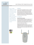
Figure 1
Ethernet Power Supply Front View
10/100BASE-TX Data & Power Output Ports, Upper 24 Ports
The Ethernet Power Supply has 24 Data & Power ports
configured as Media Dependent Interface (MDI) non-crossover.
These ports are designed to carry Ethernet data over the
standard 2-wire pairs (RJ-45 pins 1/2 and 3/6) and DC power
source over the spare wire pair (RJ-45 pins 4/5 and 7/8).
10/100BASE-TX Data Input Ports, Lower 24 Ports
The Ethernet Power Supply has 24 10BASE-T/100BASE-TXdata input ports, configured as MDI non-crossover. These ports
are designed to carry Ethernet Data only (TX/RX) over the
standard 2-wire pairs (RJ-45 pins 1/2 and 3/6).
According to the IEEE 802.3 standard, the maximum allowable
distance between two Ethernet links is 100m (328ft). The
Ethernet Power Supply meets this IEEE 802.3 requirement.
Ethernet Power Supply User s Guide
1-3
Introduction to the Ethernet Power Supply
LEDS
The LEDs in the unit indicate status of the Ethernet Power
Supply and its ports.
A main power LED on the front panel, marked by AC,
provides the Ethernet Power Supply status. The "AC" LED
illuminating green indicates that the Ethernet Power Supply is
connected to an AC outlet. The AC LED illuminating orange
indicates an internal fault. See tables 2 and 3.
One bi-color LED (green and orange) per port provides port
status. The green color indicates that the terminal unit has been
identified as "Power Over LAN enabled" and is active and
receiving power.
The orange LED indicates the port is not supplying power and
is not active. See Table 1 for additional information.
NOTE: In the event that an Ethernet device that is not Power
Over LAN enabled is connected to the Ethernet Power Supply
(indicated by the orange color or off), the Ethernet device is
unaffected because power is not being supplied.
1-4
Ethernet Power Supply User s Guide
Introduction to the Ethernet Power Supply
Ethernet Power Supply Status Indications
The following tables contain Ethernet Power Supply status
information as presented on the front panel by the LED
indicators during normal operation.
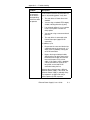
Table 1
Power Active (Green) and Power Not Active (Orange) Port Status Indications
Port LED Color
Off
Port Load Conditions
Non-active load, or
unplugged port.
Green
Active load is plugged
in and complies with
normal load
conditions.
Overload conditions or
shorted terminal port
or forced external
voltage feed (constant
DC) into the port.
Transitional mode in
which load detection is
in process or
discharged capacitor
in the PDTE.
Total aggregated
power exceeds predefined power budget.
Orange
Green —
Blinking
Orange —
Blinking
Port Voltage
Power to the port is
disconnected.
No DC voltage is
present on the spare
pairs.
Continuous nominal
DC voltage is present
on the spare pairs.
Power to the port is
disconnected.
No DC voltage is
present on the spare
pairs.
Power to the port is
disconnected.
No DC voltage is
present on the spare
pairs.
Power to the port is
disconnected.
No DC voltage is
present on the spare
pairs.
Ethernet Power Supply User s Guide
1-5
Introduction to the Ethernet Power Supply
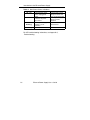
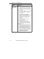
Table 2
Main Power Status Indications
LED Color
AC - Off
AC — Green
AC - Green
Blinking
AC Orange
Main Power Status
Internal power supply
unit is unplugged or
faulty.
Indicates AC power
input active.
Internal power supply
voltage is out of
tolerance.
Internal problem alarm.
Remarks
Internal power supply
voltage is too low. All
ports are disconnected.
Internal power supply
voltage is within
tolerance.
All ports are
disconnected.
Built-in self-test failed.
For LED troubleshooting information, see Appendix C,
Troubleshooting.
1-6
Ethernet Power Supply User s Guide
Introduction to the Ethernet Power Supply
Ethernet Power Supply Rear View Detail
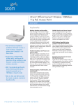
Figure 2
Ethernet Power Supply Rear View
AC Power Receptacle
The Ethernet Power Supply automatically adjusts its power
setting to any supply voltage in the range 100—240VAC
(60/50 Hz).
~
WARNING
Electrocution Hazard: Before connecting power to the Ethernet
Power Supply, see Appendix A, Safety Information.
Ethernet Power Supply User s Guide
1-7
Installing the Ethernet Power Supply
Installing the Ethernet Power Supply
0
2
Verifying Kit Contents
Unpack the kit and verify that the Ethernet Power Supply and
user s guide (this manual) are present.
Recording Identification Information
Before proceeding with the Ethernet Power Supply placement
and installation, record the serial number for future reference.
The serial number is located on the information label on the
rear of the Ethernet Power Supply.
Serial Number:
~
WARNING: Safety Information
You must read the safety information provided in Appendix˚A
before carrying out any installation, removal or any
maintenance procedure on the Ethernet Power Supply.
Ethernet Power Supply User s Guide
2-1
Installing the Ethernet Power Supply
Powering Up
The following sections describe how to get the Ethernet Power
Supply powered up and ready for operation.
!
CAUTION
The Ethernet Power Supply has no ON/OFF switch. To connect
or disconnect power to the Ethernet Power Supply, insert or
remove the power cable from the AC power receptacle on the
rear of the Ethernet Power Supply.
1) Insert a power cord into the power socket on the rear of the
Ethernet Power Supply.
2) Insert the other end of the power cord into the power
receptacle.
The Ethernet Power Supply powers up and the internal fans
begin operating.
The Ethernet Power Supply then runs through its power-on
self-test (POST), which takes less than 10 seconds. During the
POST, all ports on the Ethernet Power Supply are disabled and
the LEDs light in the following sequence:
1) The AC LED lights.
2) All Port LEDs and the AC LED light for an LED test
(green).
3) All Port LEDs and the AC LED light for an LED test
(orange).
4) The AC LED lights and remains lit (depending on the
input power source).
5) All ports are enabled for normal operation and the
Ports LEDs are ready for indications (see Table 1).
2-2
Ethernet Power Supply User s Guide
Installing the Ethernet Power Supply
Connecting Cables to the Ethernet Power Supply
All ports on the front of the Ethernet Power Supply are
configured as data "route-through" ports for all data wires
(pins 1, 2, 3, and 6).
Be sure to use a standard Category 5 straight-through cable
including all 8 wires (4 pairs).
Data In Ports
Using a standard Category 5 straight-through cable, connect
the cable leading from the Ethernet switch or hub to the "Data"
port.
Data & Power Out Ports
Using a standard Category 5 straight-through cable, connect
the cable leading to the end device to the corresponding "Data
& Power" port.
NOTE: Be sure to connect correspondingly numbered "Data"
and "Data & Power" ports.
Ethernet Power Supply User s Guide
2-3
Appendix A — Safety Information
Safety Information
A
Read the following safety information before performing any
installation, removal, or maintenance procedure on the
Ethernet Power Supply.
~
WARNING
Warnings contain directions that must be followed for personal
and product safety. Follow all directions carefully.
~
WARNING
Read the installation instructions in Section 2 before connecting
the Ethernet Power Supply to its power source.
~
WARNING
Follow basic electricity safety measures whenever connecting
the Ethernet Power Supply to its power source.
~
WARNING
The Ethernet Power Supply chassis is intended to be
grounded. Ensure the power host is connected to earth ground
during normal use.
Ethernet Power Supply User s Guide
A-1
Appendix A — Safety Information
~
WARNING
This product relies on the building installation for short-circuit
(overcurrent) protection. Make sure a fuse or circuit breaker no
larger than 120VAC, 15A. U.S. (240VAC, 10A international) is
used on the phase conductor.
~
WARNING
Do not work on the system or connect or disconnect cables
during periods of lightning activity.
~
WARNING
A voltage mismatch can cause equipment damage and may
pose a fire hazard. If the voltage indicated on the label is
different from the power outlet voltage, do not connect the
Ethernet Power Supply to this power outlet.
~
WARNING
For shelf-mounted equipment, make sure the surface is stable
and strong enough to support the equipment. Do not stack
more than four Ethernet Power Supply units on top of one
another.
~
WARNING
Ultimate disposal of this product should be handled according
to all national laws and regulations.
~
WARNING
The Ethernet Power Supply "Data" and "Data & Power" ports
are shielded RJ-45 data sockets. They cannot be used as Plain
Old Telephone Service (POTS) telephone sockets. Only RJ-45
data connectors may be connected to these sockets.
A-2
Ethernet Power Supply User s Guide
Appendix A — Safety Information
§
Installation and removal of the Ethernet Power Supply must
be carried out by qualified personnel only.
§
Power Cord Set:
The power cord must be approved for the country in which
it is used:
§
The cord set must be ULapproved and CSA certified.
§
The minimum specification for
the flexible cord is:
No. 18 AWG
Type SV or SJ
3-conductor
§
The cord set must have a rated
current capacity of at least 10A.
§
The attachment plug must be
an earth-grounding type with a
NEMA 5-15P (15A, 125V) or
NEMA 6-15P (15A, 250V)
configuration.
Denmark
§
The supply plug must comply
with section 107-2-D1, standard
DK2-1a or DK2-5a.
Switzerland
§
The supply plug must comply
with SEV/ASE 1011.
U.S.A. and
Canada
Ethernet Power Supply User s Guide
A-3
Appendix A — Safety Information
A-4
§
The appliance coupler (the connector to the unit and not
the wall plug) must have a configuration for mating with an
EN60320/IEC320 appliance inlet.
§
The socket outlet must be near to the unit and easily
accessible. You can only remove power from the unit by
disconnecting the power cord from the outlet.
§
This unit operates under SELV (Safety Extra Low Voltage)
conditions according to IEC 950. The conditions are
maintained only if the equipment to which it is connected
also operates under SELV conditions.
§
Switzerland only:
The supply plug must comply with SEV/ASE 1011.
§
France and Peru only:
This unit cannot be powered from IT supplies. If your
supplies are of IT type, this unit must be powered by 230V
(2P+T) via an isolation transformer ratio 1:1, with the
secondary connection point labeled Neutral, connected
directly to earth (ground).
Ethernet Power Supply User s Guide
Appendix B — Technical Specifications
Technical Specifications
B
Overview
This appendix lists Ethernet Power Supply hardware and
electrical specifications.
Hardware Specifications
Physical Specifications
Dimensions
Height: 44mm, 1.75 in.
Width: 433mm, 17 in.
Depth: 302mm, 11.9 in.
4.0 Kg (8.8 lb)
Weight
Environmental Specifications
Mode
Temperature
Operating
0 to 40¡C
(32 to 104¡F)
Storage
-20 to 70¡C
(-4 to 158¡F)
Humidity
10 to 90%
(no condensation allowed)
10 to 90%
(no condensation allowed)
Ethernet Power Supply User s Guide
B-1
Appendix B — Technical Specifications
Electrical Specifications
Input voltage
90 to 264VAC (47-63Hz)
Input current at 110VAC
4 Amperes Max
Total output power
200 Watts Max
Output power, per port
16.8 Watts* (typ.)
Nominal output voltage, per
port
44 - 57 VDC
* The output available per port may be lower depending on the
power budget, which is controlled by the power management
software module in the unit.
Ethernet Interface
B-2
Input (Data In): 24 Ports;
Ethernet 10/100BASE-TX
RJ-45 female socket
Output (Data & Power Out):
24 Ports; Ethernet 10/100
BASE-TX, and 48 VDC
RJ-45 female socket, with
DC voltage on pins 7/8 and
4/5
Ethernet Power Supply User s Guide
Appendix C — Troubleshooting
Troubleshooting
C
Introduction
This section helps you locate problems related to the Ethernet
Power Supply setup and functionality.
This section provides a problem and resolution sequence to
assist in troubleshooting minor operating problems. If the
provided resolutions do not solve your problem, call 3Com for
further assistance.
If you encounter problems, make sure:
— Power is applied to the Ethernet Power Supply.
— A crossover type Ethernet cable is not used.
— An input Ethernet cable is connected to the
Data port.
— An output Ethernet cable is connected to the
Data & Power port.
— The input and output cable pairs are attached to
corresponding ports.
Ethernet Power Supply User s Guide
C-1
Appendix C — Troubleshooting
Troubleshooting Table
Problem
The Ethernet
Power Supply is
plugged into a
main AC outlet,
but does not
power up.
The Ethernet
Power Supply is
plugged in and
running, but the
fans are not
working.
Resolution
Verify the use of a correct and functional
AC power cord, including good and solid
ground connection.
Verify the AC outlet is supplying power
(test with a different device) and the
voltage is between 100VAC and 240VAC
(50Hz to 60Hz).
Reconnect the Ethernet Power Supply to
the AC outlet and verify the LEDs power
up sequence. See the LEDs section
earlier in this guide.
Verify all fan openings in the case are
clear of any air-blocking materials.
If fans are not working, there may be an
internal power supply fault.
The Ethernet
Power Supply
operates, but
the AC LED is
off.
If both internal fans are working (that is,
air flows out of the case or can be heard),
there is a possible internal circuitry fault.
The Ethernet
Power Supply
has powered up
and the AC LED
is orange.
See whether the power-on self-test
(POST) sequence is as listed or not.
If fans are not working, there may be an
internal power supply fault.
If the LEDs light in the correct sequence,
the Ethernet Power Supply is fully
operational.
If the problem remains following the
POST sequence, the Ethernet Power
Supply POST detected an internal fault.
Contact 3Com.
C-2
Ethernet Power Supply User s Guide
Appendix C — Troubleshooting
Problem
The "Port LED
on one port is
not lit and the
corresponding
end device does
not operate.
Resolution
The Ethernet Power Supply did not detect
a connected end device and therefore the
port is not providing power. Verify that:
•
The end device is Power Over LAN
enabled.
•
You are using a standard UTP Category
5 cable, including all 8 wires (4 pairs).
•
If an external splitter is in use, replace
it with a new splitter. Discard the
faulty splitter.
•
You are not using a crossover twisted
pair wire.
•
The end device is connected to the
Data & Power port (upper RJ-45
connector).
In addition, try to:
•
Re-connect the same end device into
a different port on the same unit. If it
works, there is probably a faulty port
or RJ-45 connection.
•
Bypass the long twisted pair cable
and bring the end device close to the
Ethernet Power Supply and connect
to one of the ports using a short
cable. If this works, there is probably
a faulty connection or short on the
long cable, or one bad RJ-45
connection along the line.
Connect the end device into a different
Ethernet Power Supply. If this works, the
Ethernet Power Supply is probably faulty.
Try to power it up again and verify a
correct power-up LED sequence.
Ethernet Power Supply User s Guide
C-3
Appendix C — Troubleshooting
Problem
Resolution
The end device
operates, but
there is no data
link.
Verify that:
•
The Port LED on the Ethernet Power
Supply front panel is lit continuously.
•
The "Data" and "Data & Power" ports
correspond.
If an external splitter is in use, replace
it with a new splitter. Discard the
faulty splitter.
•
•
You are using a standard UTP
Category 5 cable, including all 8 wires
(4 pairs), and is 100m or less in
length between the switch and the
end device.
•
You are not using any crossover
twisted pair wires.
•
The Ethernet Power Supply is
connected to a switch or hub with a
good RJ-45 patch cord connection.
In addition, try to:
•
C-4
Bypass the long twisted pair cable
and bring the end device close to the
Ethernet Power Supply and connect
to one of the ports using a short
cable. If this works, there is probably
a faulty connection or short on the
long cable, or one bad RJ-45
connection along the line.
Ethernet Power Supply User s Guide
Appendix C — Troubleshooting
The end device
operates, but
there is no data
link
(continued).
C-5
•
Connect a different end device to the
same port. If this works and the link
is established, there is probably a
faulty data link in the end device.
•
Re-connect the end device to a
different "Data & Power" port and
remember to move the "Data" port of
the switch or hub accordingly. If this
works, there is probably a faulty "Data
& Power & Power" or "Data" port in
the Ethernet Power Supply or a bad
RJ-45 connection
One of the ports
is powering an
end device
without turning
the Port LED on.
Re-connect the end device to a different
"Data & Power" port. If the LED turns on,
there is a fault in the previous output port
(probably a faulty LED).
Is it safe to keep
the Ethernet
Power Supply
running while
the "Power Not
Active" port LED
is orange?
Yes, this condition is safe.
Ethernet Power Supply User s Guide
Limited Warranty and Regulatory Compliance
Information
3Com Corporation Limited Warranty
This warranty applies to customers located in the United States, Australia,
Canada (except Quebec), Ireland, New˚Zealand, U.K., and other English
language countries, and countries for which a translation into the local language
is not provided
Ethernet Power Supply
HARDWARE
3Com warrants to the end user ("Customer") that this hardware product will be
substantially free from material defects in workmanship and materials, under
normal use and service, for the following length of time from the date of
purchase from 3Com or its authorized reseller:
One (1) year
3Com s sole obligation under this express warranty shall be, at 3Com s option
and expense, to repair the defective product or part, deliver to Customer an
equivalent product or part to replace the defective item, or if neither of the two
foregoing options is reasonably available, refund to Customer the purchase
price paid for the defective product. All products that are replaced will become
the property of 3Com. Replacement products or parts may be new or
reconditioned. 3Com warrants any replaced or repaired product or part for
ninety (90) days from shipment, or the remainder of the initial warranty period,
whichever is longer.
SOFTWARE
3Com warrants to Customer that each software program licensed from it, except
as noted below, will, if operated as directed in the user documentation,
substantially achieve the functionality described in the user documentation for a
period of ninety (90) days from the date of purchase from 3Com or its
authorized reseller. No updates or upgrades are provided under this warranty.
3Com’s sole obligation under this express warranty shall be, at 3Com’s option
and expense, to refund the purchase price for the software product or replace
the software product with software which meets the requirements of this
warranty as described above. Customer assumes responsibility for the
selection of the appropriate programs and associated reference materials.
3Com makes no warranty or representation that its software products will meet
Customer s requirements or work in combination with any hardware or software
products provided by third parties, that the operation of the software products
will be uninterrupted or error free, or that all defects in the software products will
be corrected. For any third party products listed in the 3Com software product
documentation or specifications as being compatible, 3Com will make
reasonable efforts to provide compatibility, except where the non-compatibility is
caused by a "bug" or defect in the third party’s product or from use of the
software product not in accordance with 3Com s published specifications or user
manual.
THIS 3COM PRODUCT MAY INCLUDE OR BE BUNDLED WITH THIRD
PARTY SOFTWARE. THE WARRANTY PROVISIONS OF THIS DOCUMENT
DO NOT APPLY TO SUCH THIRD PARTY SOFTWARE. IF A SEPARATE
END USER LICENSE AGREEMENT HAS BEEN PROVIDED FOR SUCH
THIRD PARTY SOFTWARE, USE OF THAT SOFTWARE WILL BE
GOVERNED BY THAT AGREEMENT. FOR ANY APPLICABLE WARRANTY,
PLEASE REFER TO THE END USER LICENSE AGREEMENT GOVERNING
THE USE OF THAT SOFTWARE.
OBTAINING WARRANTY SERVICE
Customer must contact a 3Com Corporate Service Center or an Authorized
3Com Service Center within the applicable warranty period to obtain warranty
service authorization. Dated proof of purchase from 3Com or its authorized
reseller may be required. A User Service Order (USO), Return Material
Authorization (RMA) or Service Repair Order (SRO) number will be issued.
This number must be marked on the outside of the package sent to 3Com s
Corporate Service Center. The product must be packaged appropriately for
safe shipment and sent prepaid. It is recommended that returned products be
insured or sent by a method that provides for tracking of the package.
Responsibility for loss or damage does not transfer to 3Com until the returned
item is received by 3Com. 3Com will retain risk of loss or damage until the item
is delivered to Customer. For non-US Customers, the word ’prepaid’ shall be
omitted where this requirement is not permitted by law. The allocation of
responsibility for loss or damage stated shall be subject to any mandatory legal
requirements.
3Com shall not be responsible for any software, firmware, information, or
memory data of Customer contained in, stored on, or integrated with any
products returned to 3Com for repair, whether under warranty or not.
WARRANTIES EXCLUSIVE, WARRANTY DISCLAIMER
TO THE FULL EXTENT ALLOWED BY LAW, THE FOREGOING
WARRANTIES AND REMEDIES ARE EXCLUSIVE AND ARE IN LIEU OF ALL
OTHER WARRANTIES, TERMS OR CONDITIONS, EXPRESS OR IMPLIED,
EITHER IN FACT OR BY OPERATION OF LAW, STATUTORY OR
OTHERWISE, INCLUDING, WITHOUT LIMITATION, WARRANTIES, TERMS
OR CONDITIONS OF MERCHANTABILITY, FITNESS FOR A PARTICULAR
PURPOSE, SATISFACTORY QUALITY, CORRESPONDENCE WITH
DESCRIPTION, NON-INFRINGEMENT AND QUIET ENJOYMENT, ALL OF
WHICH ARE EXPRESSLY DISCLAIMED. 3COM NEITHER ASSUMES NOR
AUTHORIZES ANY OTHER PERSON TO ASSUME FOR˚IT ANY OTHER
LIABILITY IN CONNECTION WITH THE SALE, INSTALLATION,
MAINTENANCE OR USE OF THIS˚PRODUCT.
3COM SHALL NOT BE LIABLE UNDER THIS WARRANTY IF ITS TESTING
AND EXAMINATION DISCLOSE THAT THE ALLEGED DEFECT OR
MALFUNCTION IN THE PRODUCT DOES NOT EXIST OR WAS CAUSED BY
CUSTOMER’S OR ANY THIRD PERSON’S MISUSE, NEGLECT, IMPROPER
INSTALLATION OR TESTING, UNAUTHORIZED ATTEMPTS TO OPEN,
REPAIR OR MODIFY THE PRODUCT, OR ANY OTHER CAUSE BEYOND
THE RANGE OF THE INTENDED USE, OR BY ACCIDENT, FIRE,
LIGHTNING, POWER CUTS OR OUTAGES, OTHER HAZARDS, OR ACTS OF
GOD.
LIMITATION OF LIABILITY
TO THE FULL EXTENT ALLOWED BY LAW, 3COM ALSO EXCLUDES FOR
ITSELF AND ITS LICENSORS AND SUPPLIERS ANY LIABILITY, WHETHER
BASED IN CONTRACT OR TORT (INCLUDING NEGLIGENCE), FOR
INCIDENTAL, CONSEQUENTIAL, INDIRECT, SPECIAL, OR PUNITIVE
DAMAGES OF ANY KIND, OR FOR LOSS OF REVENUE OR PROFITS, LOSS
OF BUSINESS, LOSS OF INFORMATION OR DATA, OR OTHER FINANCIAL
LOSS ARISING OUT OF OR IN CONNECTION WITH THE SALE,
INSTALLATION, MAINTENANCE, USE, PERFORMANCE, FAILURE, OR
INTERRUPTION OF ITS PRODUCTS, EVEN IF 3COM OR ITS AUTHORIZED
RESELLER HAS BEEN ADVISED OF THE POSSIBILITY OF SUCH
DAMAGES, AND LIMITS ITS LIABILITY TO REPAIR, REPLACEMENT, OR
REFUND OF THE PURCHASE PRICE PAID, AT 3COM’S OPTION. THIS
DISCLAIMER OF LIABILITY FOR DAMAGES WILL NOT BE AFFECTED IF
ANY REMEDY PROVIDED HEREIN SHALL FAIL OF ITS ESSENTIAL
PURPOSE.
Some countries, states, or provinces do not allow the exclusion or limitation of
implied warranties or the limitation of incidental or consequential damages for
certain products supplied to consumers, or the limitation of liability for death or
personal injury, so the above limitations and exclusions may be limited in their
application to you. When the implied warranties are not allowed to be excluded
in their entirety, they will be limited to the duration of the applicable written
warranty. This warranty gives you specific legal rights which may vary
depending on local law.
GOVERNING LAW
This Limited Warranty shall be governed by the laws of the State of California,
U.S.A., and by the laws of the United States, excluding their conflicts of laws
principles. The United Nations Convention on Contracts for the International
Sale of Goods is hereby excluded in its entirety from application to this Limited
Warranty.
3Com Corporation
5400 Bayfront Plaza
P.O. Box 58145
Santa Clara, CA 95052-8145
(408) 326-5000
Rev. 6/14/01
v8.3
FCC Class A Verification Statement
WARNING: This equipment has been tested and found to comply with the limits
for a Class A digital device, pursuant to Part 15 of the FCC Rules, and the
Canadian Department of Communications Equipment Standards entitled,
Digital Apparatus, ICES-003. These limits are designed to provide reasonable
protection against harmful interference in a commercial installation. This
equipment generates, uses and can radiate radio frequency energy and, if not
installed and used in accordance with the instructions, may cause harmful
interference to radio communications. Operation of this equipment in a
residential area is likely to cause harmful interference, in which case, the user
will be required to correct the interference at the user s own expense.
Changes or modifications not expressly approved by 3Com could void the
user s authority to operate this equipment.
FCC Declaration of Conformity
Model
3CNJPSE24
Description
Ethernet Power Supply
to which this declaration relates, is in conformity with the following standards or
other normative˚documents:
ANSI C63.4-1992 Methods of Measurement
Federal Communications Commission 47 CFR Part 15, subpart B
3Com Corporation, 5400 Bayfront Plaza, P.O. Box 58145, Santa Clara, CA
95052-8145
'
2001 3Com Corporation.
All Rights Reserved
P/N: 09-2194-000
November 2001