1
Baseline Switch 2226-SFP Plus
Baseline Switch 2426-PWR Plus
Baseline Switch 2250-SFP Plus
User Guide
3CBLSF26H
3CBLSF26PWRH
3CBLSF50H
Part No.: 10017022
Manual Version: 6W104
www.3com.com
3Com Corporation
350 Campus Drive, Marlborough,
MA, USA 01752 3064
Copyright © 2008-2009, 3Com Corporation. All rights reserved. No part of this documentation may be
reproduced in any form or by any means or used to make any derivative work (such as translation,
transformation, or adaptation) without written permission from 3Com Corporation.
3Com Corporation reserves the right to revise this documentation and to make changes in content from time to
time without obligation on the part of 3Com Corporation to provide notification of such revision or change.
3Com Corporation provides this documentation without warranty, term, or condition of any kind, either implied
or expressed, including, but not limited to, the implied warranties, terms or conditions of merchantability,
satisfactory quality, and fitness for a particular purpose. 3Com may make improvements or changes in the
product(s) and/or the program(s) described in this documentation at any time.
If there is any software on removable media described in this documentation, it is furnished under a license
agreement included with the product as a separate document, in the hard copy documentation, or on the
removable media in a directory file named LICENSE.TXT or !LICENSE.TXT. If you are unable to locate a copy,
please contact 3Com and a copy will be provided to you.
UNITED STATES GOVERNMENT LEGEND
If you are a United States government agency, then this documentation and the software described herein are
provided to you subject to the following:
All technical data and computer software are commercial in nature and developed solely at private expense.
Software is delivered as “Commercial Computer Software” as defined in DFARS 252.227-7014 (June 1995) or
as a “commercial item” as defined in FAR 2.101(a) and as such is provided with only such rights as are
provided in 3Com’s standard commercial license for the Software. Technical data is provided with limited rights
only as provided in DFAR 252.227-7015 (Nov 1995) or FAR 52.227-14 (June 1987), whichever is applicable.
You agree not to remove or deface any portion of any legend provided on any licensed program or
documentation contained in, or delivered to you in conjunction with, this User Guide.
Unless otherwise indicated, 3Com registered trademarks are registered in the United States and may or may
not be registered in other countries.
3Com and the 3Com logo are registered trademarks of 3Com Corporation.
All other company and product names may be trademarks of the respective companies with which they are
associated.
ENVIRONMENTAL STATEMENT
It is the policy of 3Com Corporation to be environmentally-friendly in all operations. To uphold our policy, we
are committed to:
Establishing environmental performance standards that comply with national legislation and regulations.
Conserving energy, materials and natural resources in all operations.
Reducing the waste generated by all operations. Ensuring that all waste conforms to recognized environmental
standards. Maximizing the recyclable and reusable content of all products.
Ensuring that all products can be recycled, reused and disposed of safely.
Ensuring that all products are labelled according to recognized environmental standards.
Improving our environmental record on a continual basis.
End of Life Statement
3Com processes allow for the recovery, reclamation and safe disposal of all end-of-life electronic components.
Regulated Materials Statement
3Com products do not contain any hazardous or ozone-depleting material.
Environmental Statement about the Documentation
The documentation for this product is printed on paper that comes from sustainable, managed forests; it is fully
biodegradable and recyclable, and is completely chlorine-free. The varnish is environmentally-friendly, and the
inks are vegetable-based with a low heavy-metal content.
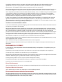
About This Manual
Organization
3Com Baseline Switch User Guide is organized as follows:
Chapter
Contents
1 Getting Started
This chapter contains introductory information about the
installation of the switch and how they can be used in your
network.
2 Connecting To the Web Interface
This chapter introduces the setting the menu items and
buttons that are available on the Web interface.
3 Configuring the Switch
This chapter introduces how to configure the switch in detail.
4 Troubleshooting
This chapter lists some issues that you may encounter while
installing, using, and managing the switch, with suggested
courses of corrective action to take.
5 CLI Reference Guide
This chapter describes using the Command Line Interface
(CLI) to manage the switch.
6 Obtaining
Product
Support
for
Your
This chapter introduces how to get support for your product.
7 Safety Information
This chapter describes the important safety information for
you product.
8 Regulatory Notices
This chapter describes the important regulatory notices for
you product.
9 Glossary
This chapter lists the main glossaries for the manual.
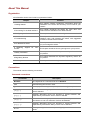
Conventions
The manual uses the following conventions:
Command conventions
Convention
Description
Boldface
The keywords of a command line are in Boldface.
italic
Command arguments are in italic.
[]
Items (keywords or arguments) in square brackets [ ] are optional.
{ x | y | ... }
Alternative items are grouped in braces and separated by vertical bars.
One is selected.
[ x | y | ... ]
Optional alternative items are grouped in square brackets and
separated by vertical bars. One or none is selected.
{ x | y | ... } *
Alternative items are grouped in braces and separated by vertical bars.
A minimum of one or a maximum of all can be selected.
[ x | y | ... ] *
Optional alternative items are grouped in square brackets and
separated by vertical bars. Many or none can be selected.
&<1-n>
The argument(s) before the ampersand (&) sign can be entered 1 to n
times.
Convention
#
Description
A line starting with the # sign is comments.
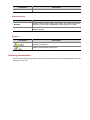
GUI conventions
Convention
Description
Boldface
Window names, button names, field names, and menu items are in
Boldface. For example, the New User window appears; click OK.
>
Multi-level menus are separated by angle brackets. For example, File >
Create > Folder.
Symbols
Convention
Description
Means reader be careful. Improper operation may cause data loss or
damage to equipment.
Means a complementary description.
Obtaining Documentation
You can access the most up-to-date 3Com product documentation on the World Wide Web at this URL:
http://www.3com.com.
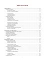
Table of Contents
1 Getting Started···········································································································································1-1
Introducing the Switch·····························································································································1-1
Overview of the Switch ····················································································································1-1
Summary of Hardware Features ·····································································································1-1
Front View Detail ·····························································································································1-2
LED Status Indicators······················································································································1-3
System Specifications ·····················································································································1-4
Installing the Switch ································································································································1-5
Before You Begin ····························································································································1-5
Package Contents ···························································································································1-5
Positioning the Switch ·····················································································································1-5
Rack-Mounting or Free-Standing ····································································································1-6
Supplying Power to the Switch········································································································1-7
Checking for Correct Operation·······································································································1-8
Using SFP Transceivers··················································································································1-8
Performing Spot Checks················································································································1-10
Configuring IP Address ·························································································································1-10
Automatic IP Configuration using DHCP·······················································································1-11
Manual IP Configuration ················································································································1-11
2 Connecting To the Web Interface ············································································································2-1
Requirements for Accessing the Web Interface ·····················································································2-1
Choosing a Web Browser ·······················································································································2-1
Default User and Password ····················································································································2-2
Logging On to the Web Interface ············································································································2-2
Navigating the Web Interface··················································································································2-2
Menu················································································································································2-2
Buttons ············································································································································2-5
3 Configuring the Switch ·····························································································································3-1
Configuring System Access ····················································································································3-1
Defining System Access··················································································································3-1
Modifying System Access ···············································································································3-2
Removing System Access···············································································································3-3
Viewing System Access Settings ····································································································3-3
Configuring IP and MAC Address Information························································································3-4
Defining IP Address·························································································································3-4
Configuring ARP Settings················································································································3-5
Configuring MAC Address Table·····································································································3-7
Configuring Port ····································································································································3-11
Configuring Port Basic Settings·····································································································3-11
Configuring PoE ····························································································································3-14
Viewing Port Statistics ···················································································································3-16
Configuring VLAN ·································································································································3-18
i
Creating VLANs·····························································································································3-19
Modifying VLAN·····························································································································3-19
Modifying Port VLAN Settings ·······································································································3-20
Renaming VLANs ··························································································································3-21
Removing VLANs ··························································································································3-21
Viewing VLAN Details····················································································································3-22
Viewing VLAN Port Details············································································································3-23
Aggregating Port ···································································································································3-24
Overview········································································································································3-24
LACP ·············································································································································3-24
Link Aggregation Types·················································································································3-24
Configuring Link Aggregation ········································································································3-25
Configuring LACP··························································································································3-28
Configuring STP····································································································································3-29
Configuring IGMP Snooping ·················································································································3-35
Defining IGMP Snooping ···············································································································3-35
Configuring ACL····································································································································3-36
Configuring MAC Based ACL········································································································3-36
Configuring IP Based ACL ············································································································3-40
Configuring ACL Binding ···············································································································3-44
Configuring QoS····································································································································3-46
Configuring CoS ····························································································································3-46
Configuring Queue Algorithm ········································································································3-47
Configuring CoS to Queue ············································································································3-48
Configuring DSCP to Queue ·········································································································3-49
Configuring Trust Mode ·················································································································3-51
Configuring Bandwidth Settings ····································································································3-51
Configuring Voice VLAN················································································································3-53
Configuring SNMP ································································································································3-58
Defining SNMP Communities········································································································3-58
Removing SNMP Communities·····································································································3-59
Defining SNMP Traps····················································································································3-59
Removing SNMP Traps·················································································································3-60
Configuring LLDP··································································································································3-61
LLDP Overview······························································································································3-61
Configuring Global LLDP Parameters ···························································································3-61
Configuring Port-Level LLDP Parameters ·····················································································3-62
Viewing LLDP Information ·············································································································3-64
Managing Switch Security·····················································································································3-66
Defining Port-Based Authentication (802.1X) ···············································································3-66
Defining Radius Client ···················································································································3-69
Configuring LDB ····························································································································3-70
Configuring Broadcast Storm Control····························································································3-73
Managing System Information ··············································································································3-74
Viewing Basic Settings ··················································································································3-75
Configuring System Name ············································································································3-76
Configuring System Time ··············································································································3-77
ii
Save Configuration ························································································································3-78
Resetting the Switch······················································································································3-79
Managing System Files·························································································································3-79
Managing System Logs ························································································································3-82
Configuring Logging ······················································································································3-83
Viewing Logs ·································································································································3-84
Managing Switch Diagnostics ···············································································································3-85
Configuring Port Mirroring ·············································································································3-85
Configuring Cable Diagnostics ······································································································3-86
4 Troubleshooting ········································································································································4-1
Resetting to Factory Defaults··················································································································4-1
Forgotten Password ································································································································4-1
Reset the switch ······························································································································4-1
Configure a new user ······················································································································4-2
Forgotten Static IP Address ····················································································································4-2
Solving LED Issues ·································································································································4-2
5 CLI Reference Guide ·································································································································5-1
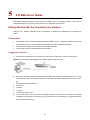
Getting Started with the Command Line Interface··················································································5-1
Prerequisites····································································································································5-1
Logging on to the CLI ······················································································································5-1
CLI Features ···········································································································································5-2
Online Help······································································································································5-2
Command History····························································································································5-3
Error Messages ·······························································································································5-3
Command Edit·································································································································5-4
CLI Configuration ····································································································································5-4
display ip··········································································································································5-4
display management-vlan ···············································································································5-5
display version·································································································································5-6
ip address ········································································································································5-6
ip address dhcp-alloc·······················································································································5-6
ip gateway ·······································································································································5-7
localuser ··········································································································································5-7
management-vlan····························································································································5-8
management-vlan port·····················································································································5-8
ping ··················································································································································5-9
quit ·················································································································································5-10
reboot·············································································································································5-10
restore ···········································································································································5-11
save ···············································································································································5-11
tftp update······································································································································5-12
6 Obtaining Support for Your Product ·······································································································6-1
Register Your Product·····························································································································6-1
Purchase Value-Added Services ············································································································6-1
Access Software Downloads ··················································································································6-1
Telephone Technical Support and Repair ······························································································6-1
iii
Contact Us ··············································································································································6-2
7 Safety Information ·····································································································································7-1
Important Safety Information···················································································································7-1
8 Regulatory Notices ····································································································································8-1
FCC Statement ·······································································································································8-1
Information to the User····························································································································8-1
ICES Statement ······································································································································8-1
CE Statement (Europe)···························································································································8-1
VCCI Statement ······································································································································8-2
9 Glossary ·····················································································································································9-1
iv
1
Getting Started
z
This manual applies to the Baseline Switch 2250-SFP Plus, Baseline Switch 2226-SFP Plus, and
Baseline Switch 2426-PWR Plus, which are hereinafter referred to as the switch.
z
This manual takes the Web interfaces of the Baseline Switch 2426-PWR Plus as an example.
This chapter contains introductory information about the installation of the switch and how they can be
used in your network. It covers the following topics:
z
Introducing the Switch
z
Installing the Switch
z
Configuring IP Address
Introducing the Switch
This chapter covers summary information about the hardware and the following topics:
z
Overview of the Switch
z
Summary of Hardware Features
z
Front View Detail
z
LED Status Indicators
z
System Specifications
Overview of the Switch
z
The Baseline Switch 2226-SFP Plus is a versatile, easy-to-use configurable switch.
z
The Baseline Switch 2426-PWR Plus is a versatile, easy-to-use configurable Power-over-Ethernet
(PoE) Switch.
z
The Baseline Switch 2250-SFP Plus is a versatile, easy-to-use configurable switch.
Each Switch is ideal for users who want the high-speed performance of 10/100 switching with the added
functionality of Gigabit copper and fiber links, but do not need sophisticated management capabilities.
The Switch is shipped ready for use. No configuration is necessary.
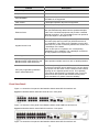
Summary of Hardware Features
Table 1-1 Summarizes the hardware features supported by the Switch.
Table 1-1 Hardware Features
Feature
Description
Addresses
Up to 8192 supported.
Auto-negotiation
Supported on all ports.
1-1
Feature
Description
Forwarding Modes
Store and Forward.
Duplex Modes
Half and full duplex on all front panel ports.
Auto MDI/MDIX
Supported on all ports. If fiber SFP transceivers are used,
Auto MDIX is not supported.
Flow Control
In full duplex operation all ports are supported.
Traffic Prioritization
Four traffic queues per port.
10/100 Mbps ports.
Ethernet Ports
Gigabit Combo Ports
Each port automatically determines the speed and duplex
mode of the connected equipment and provides a suitable
switched connection. The 10/100 Mbps ports can operate in
either half-duplex or full-duplex mode.
The 2 Gigabit combo ports support fiber Gigabit Ethernet
short-wave (SX) and long-wave (LX) SFP transceivers in
any combination. This offers you the flexibility of using SFP
transceivers to provide connectivity between the Switch and
a 1000 Mbps core network.
When an SFP port is in operation, the corresponding
1000BASE-T port is disabled. The 1000 Mbps connections
can only operate in full duplex mode.
Mounting
19-inch rack or standalone mounting.
Fanless design (supported by
Baseline Switch 2226-SFP Plus and
Baseline Switch 2250-SFP Plus)
Silent operation whether used in a rack or desktop situation.
PoE (Only supported by Baseline
Switch 2426-PWR Plus)
Each RJ-45 port supports the IEEE 802.3af PoE standard.
Any 802.3af compliant device attached to a port can directly
draw power from the switch over the Ethernet cable without
requiring its own separate power source. This capability
gives network administrators centralized power control for
devices such as IP phones and wireless access points,
which translates into greater network availability.
Front View Detail
Figure 1-1 shows the front panel of the Baseline Switch 2226-SFP Plus 26-Port unit.
Figure 1-1 Baseline Switch 2226-SFP Plus 26-Port—front panel.
Figure 1-2 Shows the front panel of the Baseline Switch 2426-PWR Plus 26-Port unit.
Figure 1-2 Baseline Switch 2426-PWR Plus 26-Port—front panel.
Figure 1-3 shows the front panel of the Baseline Switch 2250-SFP Plus 50-Port unit.
1-2
Figure 1-3 Baseline Switch 2250-SFP Plus 50-Port—front panel.
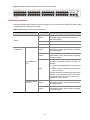
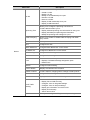
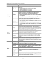
LED Status Indicators
The Switch provides LED indicators on the front panel for your convenience to monitor the switch. Table
1-2 describes the meanings of the LEDs.
Table 1-2 Description on the LEDs of the Switch
LED
Status
Green
The switch starts normally. The LED flashes
when the system is performing Power-On
Self-Test (POST).
Yellow
The system has failed the POST.
OFF
The switch is powered off.
Green
The port works at the rate of 100 Mbps; the
LED flashes quickly when the port is sending
or receiving data.
Yellow
The port works at the rate of 10 Mbps; the
LED flashes quickly when the port is sending
or receiving data.
Power
Link/Activity
Description
The link has not been established, either
nothing is connected to the port, or there is a
problem:
10/100BASE-T
port
z
OFF
z
Check that the attached device is powered
on.
Check that the cable is the correct type
and is not faulty.
If these checks do not identify the cause of the
problem, it may be that the unit or the device
connected to the port is faulty. Contact your
supplier for further advice.
10/100/1000BAS
E-T port
Green
The port works at the rate of 1000 Mbps; the
LED flashes quickly when the port is sending
or receiving data.
Yellow
The port works at the rate of 10/100 Mbps; the
LED flashes quickly when the port is sending
or receiving data.
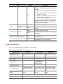
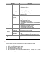
1-3
LED
Status
Description
The link has not been established, either
nothing is connected to the port, or there is a
problem:
z
z
OFF
z
Check that the attached device is powered
on.
Check that the cable or fiber is the correct
type and is not faulty.
For fiber connections, ensure that the
receive (RX) and transmit (TX) cable
connectors are not swapped.
If these checks do not identify the cause of the
problem, it may be that the unit or the device
connected to the port is faulty. Contact your
supplier for further advice.
Duplex
Module Active
10/100/1000BAS
E-T port
Yellow
The port is in full duplex mode.
OFF
The port is not connected, or is in half duplex
mode.
Green
The SFP module is inserted.
OFF
The SFP module is not inserted or is not
recognized.
Green
The port is supplying power to the device
connected to it.
OFF
The port is not supply power to the device
connected to it or not connected.
SFP port
PoE Power (Only supported by
Baseline Switch 2426-PWR Plus)
System Specifications
Table 1-3 contains the system specifications of the Switch.
Table 1-3 System specifications of the Switch.
Specification
2226-SFP
2426-PWR
Physical dimensions
(H×W×D)
44 mm×440 mm×170
mm
44 mm×440 mm×238
mm
44 mm×440 mm×238
mm
Weight
1.6 kg
3.2 kg
2.9 kg
Console port
1
1
1
Ethernet port
24
24 (Each port can
provide a power
supply of 25 W)
48
Gigabit Combo port
2
2
2
AC Input voltage
Rated voltage range:
100–240V AC, 50/60
Hz
Rated voltage range:
100–240V AC, 50/60
Hz
Rated voltage range:
100–240V AC, 50/60
Hz
Power consumption (full
load)
17 W
205 W
26 W
Operating temperature
0°C to 40°C (32°F to 113°F)
Storage temperature
–10°C to +70°C (14°F to 158°F)
1-4
2250-SFP
Specification
2226-SFP
Operating humidity
(noncondensing)
20% to 85%
Storage humidity
(noncondensing)
10% to 90%
2426-PWR
2250-SFP
Installing the Switch
This section contains information that you need to install and set up the switch. It covers the following
topics:
z
Before You Begin
z
Package Contents
z
Positioning the Switch
z
Rack-Mounting or Free-Standing
z
Supplying Power to the Switch
z
Checking for Correct Operation
z
Using SFP Transceivers
z
Performing Spot Checks
Before You Begin
Before installing or removing any components from the switch or carrying out any maintenance
procedures, read the safety information provided in Safety Information of this guide.
Package Contents
The Baseline Switch packaging contains the following for all units:
z
One product sealed in a plastic bag
z
One CD
z
One Safety and Regulatory Information manual
z
One warranty card
z
One Mounting Kit
z
One DB-9 to RJ-45 cable
Positioning the Switch
The switch is suitable for use in an office environment where it can be free-standing or mounted in a
standard 19-inch equipment rack.
Alternatively, the switch can be rack-mounted in a wiring closet or equipment room. A mounting kit,
containing two mounting brackets and four screws, is supplied with the switch.
When deciding where to position the switch, ensure that:
z
It is accessible and cables can be connected easily.
z
Cabling is away from sources of electrical noise. These include lift shafts, microwave ovens, and
air conditioning units. Electromagnetic fields can interfere with the signals on copper cabling and
introduce errors, therefore slowing down your network.
z
Water or moisture cannot enter the case of the unit.
1-5
z
Air flow around the unit and through the vents on the side of the case is not restricted (3Com
recommends that you provide a minimum of 25 mm (1 in.) clearance).
z
The air is as free from dust as possible.
z
Temperature operating limits are not likely to be exceeded. It is recommended that the unit is
installed in a clean, air conditioned environment.
It is always good practice to wear an anti-static wrist strap when installing network equipment,
connected to a ground point. If one is not available, try to keep in contact with a grounded rack and
avoid touching the unit's ports and connectors, if possible. Static discharge can cause reliability
problems in your equipment.
Rack-Mounting or Free-Standing
The unit can be mounted in a 19-inch equipment rack using the mounting kit or it can be free standing.
Do not place objects on top of the unit or stack.
If installing the switch in a free-standing stack of different size Baseline or Super stack 3 units, the
smaller units must be installed above the larger ones. Do not have a free-standing stack of more than
six units.
Using the Mounting Kit
The switch is supplied with two mounting brackets and four screws. These are used for rack mounting
the unit. When mounting the unit, you should take note of the guidelines given in Positioning the Switch.
The switch is 1U (1.7 inches) high and will fit in a standard 19-inch rack.
Disconnect all cables from the unit before continuing. Remove the self-adhesive pads from the
underside of unit, if already fitted.
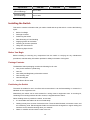
To rack-mount the switch:
1)
Place the unit the right way up on a hard, flat surface with the front facing towards you.
2)
Locate a mounting bracket over the mounting holes on one side of the unit.
3)
Insert the two screws supplied in the mounting kit and fully tighten with a suitable screwdriver.
1-6
Figure 1-4 Rack Mounting the Unit
4)
Repeat steps 2 and 3 for the other side of the unit.
5)
Insert the unit into the 19-inch rack and secure with suitable screws (not provided).
6)
Reconnect the cables.
Placing Units On Top of Each Other
If the switch units are free-standing, up to six units can be placed one on top of the other. If you are
mixing a variety of Baseline and Super Stack units, the smaller units must be positioned at the top.
If you are placing switch units one on top of the other, you must use the self-adhesive rubber pads
supplied. Apply the pads to the underside of each switch, sticking one in the marked area at each
corner.
Place the switch units on top of each other, ensuring that the pads of the upper unit line up with the
recesses of the lower unit.
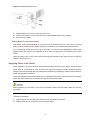
Supplying Power to the Switch
Power problems can be the cause of serious failures and downtime in your network. Ensure that the
power input to your system is clean and free from sags and surges to avoid unforeseen network
outages. 3Com recommends that you install power conditioning, especially in areas prone to blackout,
power dips and electrical storms.
The unit is intended to be grounded. Ensure it is connected to earth ground during normal use. Installing
proper grounding helps to avoid damage from lightning and power surges.
Before powering on the switch, verify that the network cables and the power cable are securely
connected.
To power on the switch:
1)
Plug the power cord into the power socket on the rear panel of the switch.
2)
Plug the other end of the power cord into a power outlet.
1-7
Checking for Correct Operation
After you power on the switch, it automatically performs a power-on self-test (POST). During POST, the
Power LED on the front panel of the switch flashes green.
When POST is complete, the Power LED turns green. If the Power LED turns yellow after POST, it
means that POST failed and the switch has entered fail-safe mode.
The following summarizes the possible colors for the Power LED after POST.
Table 1-4 Summarizes the possible colors for the Power LED after POST
Status
Meaning
Green
The unit is powered on and ready for use.
Yellow
Power-on self-test or loop back test failed. The switch is in fail-safe mode.
This can happen if a port or ports fail when the switch was powered on.
The unit is not receiving power.
z
Off
z
Verify that the power cord is connected correctly, and then try powering on
the switch again
If the switch still does not operate, contact your 3Com network supplier
If POST fails, try the following:
z
Power off the switch, and then power it on again. Check the Power LED and see if POST was
successfully completed.
z
Reset the switch. See Resetting to Factory Defaults.
Resetting the switch to its factory default erases all your settings. You will need to reconfigure the switch
after you reset it.
If these do not resolve the issue:
z
Check the 3Com Knowledgebase for a solution. To visit the 3Com Knowledgebase Web site, start
your Web browser, and then enter http://knowledgebase.3com.com.
z
Contact your 3Com network supplier for assistance.
Using SFP Transceivers
The following sections describe how to insert an SFP transceiver into an SFP slot.
SFP transceivers are hot-insertable and hot-swappable. You can remove them from and insert them
into any SFP port without having to power down the switch.
1-8
Approved SFP Transceivers
The following list of approved SFP transceivers is correct at the time of publication:
z
3CSFP91 SFP (SX)
z
3CSFP92 SFP (LX)
To access the latest list of approved SFP transceivers for the switch on the 3Com Web site, enter this
URL into your Internet browser: http://www.3com.com
3Com recommends using 3Com SFPs on the switch. If you insert an SFP transceiver that is not
supported, the switch will not recognize it.
Inserting an SFP Transceiver
To be recognized as valid, the SFP transceiver must have the following characteristics:
1000BASE-SX or 1000BASE-LX media type:
z
1000BASE-SX SFP transceiver
Use this transceiver to connect the switch directly to a multimode fiber-optic cable.
z
1000BASE-LX SFP transceiver
Use this transceiver to connect the switch directly to a single mode fiber-optic cable or to multi-mode
fiber using a conditioned launch cable.
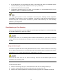
To activate the SFP port:
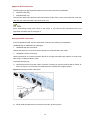
1)
Hold the transceiver so that the fiber connector is toward you and the product label is visible, as
shown in Figure 1-5.Ensure the wire release lever is closed (in the upright position).
Figure 1-5 Inserting an SFP Transceiver
Product label
Wire release lever
Suitable slot on
host Switch
2)
Gently slide the transceiver into the SFP slot until it clicks into place.
1-9
SFP transceivers are keyed and can be properly inserted only one way. If the transceiver does not click
when you insert it, remove it, turn it over, and reinsert it.
3)
Remove the plastic protective cover, if fitted.
4)
Connect the fiber cable.
5)
Attach a male duplex LC connector on the network cable into the duplex LC connector on the
transceiver.
6)
Connect the other end of the cable to a device fitted with an appropriate Gigabit Ethernet
connection.
7)
Check the Module Active LEDs on the front of the switch to ensure that the SFP transceiver is
operating correctly.
Removing an SFP Transceiver
To remove an SFP transceiver:
1)
Disconnect the cable from the transceiver.
2)
Move the wire release lever downwards until it is pointing toward you.
3)
Pull the wire release lever toward you to release the catch mechanism.
The SFP transceiver should slide out easily.
Performing Spot Checks
At frequent intervals, you should visually check the switch. Regular checks can give you an early
warning of a possible failure; any problems can then be attended to when there will be least effect on
users.
3Com recommends periodically checking the items listed in Table 1-5.
Table 1-5 Items to Check
Item
Operation
Cooling fan
Where possible, check that the cooling fan is operating by listening to the unit.
The fan is fitted near to the front right hand side of the unit (when viewed from
the front).
Cabling
Check that all external cabling connections are secure and that no cables are
pulled taut.
Configuring IP Address
The switch’s IP configuration is determined automatically using DHCP, or manually using values you
assign.
By default, the switch will use its default IP information. The default IP address is 169.254.xxx.xxx. If the
MAC address is 08004E000102, the IP address would be 169.254.1.2.
1-10
Automatic IP Configuration using DHCP
When you use the automatic IP configuration method, the switch tries to obtain its IP information without
requesting user intervention from a DHCP server on the network.
You should use the automatic IP configuration method if:
z
Your network uses DHCP to allocate IP information, or
z
Flexibility is needed. If the switch is deployed onto a different subnet, it will automatically
reconfigure itself with an appropriate IP address, instead of you having to manually reconfigure the
switch.
You can use ip address dhcp-alloc command to define automatic IP configuration method and use
display ip command to view the automatically allocated IP Information through the Console Port (see
CLI Reference Guide).
Manual IP Configuration
When you configure the IP information manually, the switch remembers the information that you enter
until you change it again.
You should use the manual IP configuration method if:
z
You do not have a DHCP server on your network, or
z
You want to remove the risk of the IP address ever changing, or
z
Your DHCP server does not allow you to allocate static IP addresses.
For most installations, 3Com recommends that you configure the switch IP information manually. This
makes management simpler and more reliable as it is not dependent on a DHCP server, and eliminates
the risk of the IP address changing.
You can use ip address command to configure the static IP for your switch through the Console Port
(see CLI Reference Guide).
1-11
2
Connecting To the Web Interface
The switch has a built-in Web interface that you can use to set the user password, change the IP
address that is assigned to the switch, and configure its advanced settings.
This chapter introduces the setting the menu items and buttons that are available on the Web interface.
The following topics are covered:
z
Requirements for Accessing the Web Interface
z
Choosing a Web Browser
z
Default User and Password
z
Logging On to the Web Interface
z
Navigating the Web Interface
Requirements for Accessing the Web Interface
To connect to the Web interface, you need the following:
z
Ensure that the switch is connected to the network using a Category 5 twisted pair Ethernet cable
with RJ-45 connectors.
z
Ensure that you know your switch’s IP address. See Configuring IP Address.
z
Check that your management workstation is on the same subnet as your switch.
z
Choose a suitable Web browser.
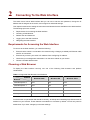
Choosing a Web Browser
To display the Web interface correctly, use one of the following Web browsers and platform
combinations:
Table 2-1 Supported Web Browsers and Platforms
Platform
Browser
Windows 2000
Windows XP
Windows Vista
Internet Explorer 6
Yes
Yes
Yes
Internet Explorer 7
Yes
Yes
Yes
Firefox 1.5
Yes
Yes
Yes
Firefox 2
Yes
Yes
Yes
Netscape 8
Yes
Yes
Yes
For the browser to operate the Web interface correctly, JavaScript and Cascading Style Sheets must be
enabled on your browser. These features are enabled on a browser by default. You will only need to
enable them if you have changed your browser settings.
2-1
Default User and Password
If you intend to manage the switch or to change the default password, you must log in with a valid user
name and password. The switch has one default user name. The default user is listed in Table 2-2.
Table 2-2 Default User and Password
User Name
admin
Default Password
Access Level
Management: The user can access and change all
manageable parameters
-
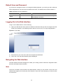
Logging On to the Web Interface
To log on to the Web interface, do the following:
1)
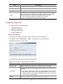
Open your Web browser and enter the IP address of the switch that you wish to manage in the URL
locator (For example, in the following format: http://xxx.xxx.xxx.xxx). The Login Page appears:
Figure 2-1 Login Page
2)
Enter admin as your user name and leave the password field blank.
3)
Click Login, The main Web interface page is displayed.
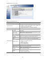
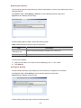
Navigating the Web Interface
The Web interface has been designed to enable you to easily perform advanced configuration tasks
and view information about the switch.
Menu
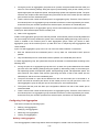
The menu is located on the left side of the Web interface. When you click an item on the menu, the
related screen appears in the main part of the interface. Some menu items will give you sub-menu tabs
to choose from.
2-2
Figure 2-2 Switch Screen Layout
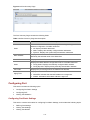
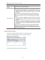
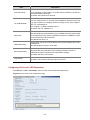
Table 2-3 Available Menu Items
Menu Item
Description
Contains tabs that allow you to:
z
Device Summary
z
Save Configuration
Provide a summary of the switch’s basic settings and
versions of current components.
Display the description for each color coded port.
Saves the switch’s configuration
IP Setup
Allows you to setup, modify, or view the IP configuration
parameters.
ARP Setting
Allows a host to communicate with other hosts when only the
IP address of its neighbors is known.
Backup & Restore
Allows you to backup and restore the switch’s configuration.
Firmware
Upgrade
Allows you to upgrade the current firmware via HTTP
Reset
Allows you to reset the switch to factory default settings
Contains tabs that allow you to:
Administration
z
System Access
z
z
z
Display user summary information.
Create a new user.
Modify existing users.
Remove existing users.
System Name
Allows you to set the system name.
System Time
Allows you to set the system time.
Logging
System Logs record and manage events and report errors
and informational messages
Contains tabs that allow you to:
SNMP
z
z
Add community strings.
Remove community strings.
2-3
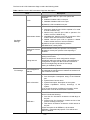
Menu Item
Description
Contains tabs that allow you to:
z
z
VLAN
z
z
z
z
z
Create a VLAN.
Modify a VLAN.
Modify VLAN membership for a port.
Rename a VLAN.
Remove a VLAN.
Display VLAN membership for a port.
Display VLAN information.
Allows you to configure a Spanning Tree Protocol.
Contains tabs that allow you to:
Spanning Tree
z
z
z
Device
Display selected spanning tree information for every port.
Display individual port spanning tree information.
Modify the spanning tree settings for a port.
IGMP Snooping
Allows you to enable or disable IGMP snooping and IGMP
query modes.
Broadcast Storm
Allows you to enable or disable broadcast control.
ACL
Configures the ACL.
MAC Based ACL
Configures MAC Based ACL on the switch.
IP Based ACL
Configures IP Based ACL on the switch.
ACL Binding
Configures ACL Binding on the switch.
QoS
Configures QoS settings.
Contains tabs that allow you to:
CoS
z
z
Displays CoS default settings assigned to ports.
Defines CoS
Queue
Configures Queue Setting.
CoS to Queue
Displays and defines CoS to Queue.
DSCP to Queue
Contains fields for mapping DSCP settings to traffic queues.
Trust
Configures Trust Settings.
Bandwidth
Displays and defines Bandwidth Settings.
Contains tabs that allow you to:
z
VoIP Traffic
Setting
z
z
z
z
z
LLDP
Display Voice VLAN summary.
Configure Voice VLAN global settings.
Configure Voice VLAN port settings.
Display port information for Voice VLAN.
Display OUI summary.
Add or remove OUI.
Allows you to configure LLDP global and port settings.
2-4
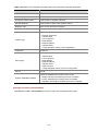
Menu Item
Description
Contains tabs that allow you to:
Administration
z
z
z
Display selected port information for the entire switch.
Display individual port information.
Modify the port settings.
Contains tabs that allow you to:
z
Link Aggregation
Port
z
z
z
Display link aggregation summary.
Create an aggregation group.
Modify the port memberships.
Remove an aggregation group.
LACP
Configures the LACP.
Statistics
Display statistics for a selected port.
PoE(Only
supported by
2426-PWR Plus)
Contains tabs that allow you to:
z
z
Display PoE summary.
Configure PoE settings.
Contains tabs that allow you to:
Radius Client
z
z
Security
Display Radius Client information.
Configure Radius Client settings and set authentication
parameters.
Contains tabs that allow you to:
802.1X
z
z
z
Display system authentication summary.
Display detailed information per port.
Configure system authentication settings.
Address Table
Displays MAC address table information for ports and VLANs.
Port Mirroring
Monitor traffic going in or out of ports.
Monitoring
Contains tabs that allow you to:
Cable
Diagnostics
z
z
Display selected cable diagnostics information for all
ports.
Display all cable diagnostics information for a single port.
Help
Displays 3Com contact information and describes how to use
the online help system.
Logout
Allows you to securely log off the Web interface.
Buttons
Depending on the screen that is currently displayed, the following buttons may appear:
z
Apply: Click to apply any changes that you have made.
z
Cancel: Click to discard any unsaved changes.
z
Select All: Allows the user to select all ports.
z
Select None: Removes the ports selected.
z
Help: Click to display the context-sensitive help information for the screen that is currently
displayed. The help pages provide information on the tasks that you can perform on each screen.
2-5
3
Configuring the Switch
Configuring System Access
Network administrators can define user name, password, and access level for users using the System
Access Interface. The Multi-Session Web feature is enabled on switch and allows 10 users to be
created and access the switch concurrently. Access levels provide read or read/write permissions to
users for configuring the switch. Login information is managed in the local database. A unique password
is required of each user. Two access levels exist on the Web Interface:
z
Management access level: Provides the user with read/write access rights. There is always one
management level user configured for the switch.
z
Monitor access level: Provides the user with read-only system access rights.
This section contains the following topics:
z
Defining System Access
z
Modifying System Access
z
Removing System Access
z
Viewing System Access Settings
To ensure that unauthorized users do not access the Web interface, 3Com recommends that you set an
admin password when you first configure the switch.
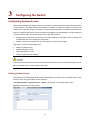
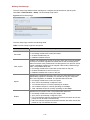
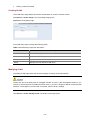
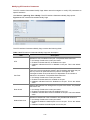
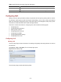
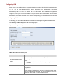
Defining System Access
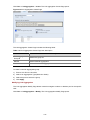
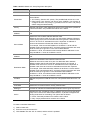
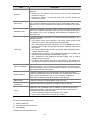
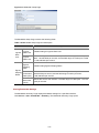
The System Access Setup Page allows network administrators to define users, passwords, and access
levels for users using the System Access Interface.
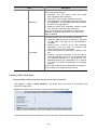
Click Administration > System Access > Setup. The System Access Setup Page opens.
Figure 3-1 System Access Setup Page
3-1
The System Access Setup Page contains the following fields:
Table 3-1 System Access Setup Page item description
Item
User Name
Description
Defines the user name. The default value is admin.
Defines the user access level. The lowest user access level is Monitor and
the highest is Management.
Access Level
z
z
Management: Provides the user with read and write access rights. This
is the default.
Monitor: Provides the user with read access rights.
Password
Defines the local user password. The default is blank.
Confirm Password
Verifies the password.
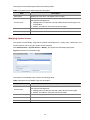
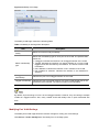
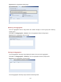
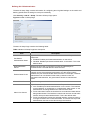
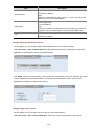
Modifying System Access
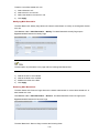
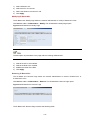
The System Access Modify Page allows network administrators to modify users, passwords, and
access levels for users using the System Access Interface.
Click Administration > System Access > Modify. The System Access Modify Page opens.
Figure 3-2 System Access Modify Page
The System Access Modify Page contains the following fields:
Table 3-2 System Access Modify Page item description
Item
Access Level
Description
Defines the user access level. The lowest user access level is Monitor and
the highest is Management.
z
z
Management: Provides the user with read and write access rights.
Monitor: Provides the user with read access rights.
Password Modify
Enables modifying a password for an existing user.
Password
Modifies the local user password.
Confirm Password
Verifies the password.
3-2
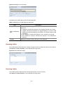
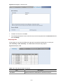
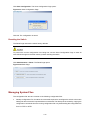
Removing System Access
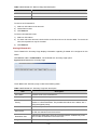
The System Access Remove Page allows network administrators to remove users from the System
Access Interface.
The last user with management access may not be deleted.
Click Administration > System Access > Remove. The System Access Remove Page opens.
Figure 3-3 System Access Remove Page
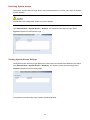
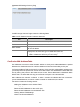
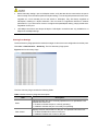
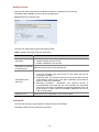
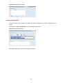
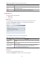
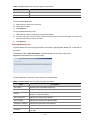
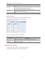
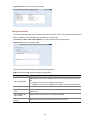
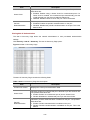
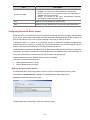
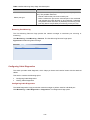
Viewing System Access Settings
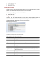
The System Access Summary Page displays the current users and access levels defined on the switch.
Click Administration > System Access > Summary. The System Access Summary Page opens.
Figure 3-4 System Access Summary Page
The System Access Summary Page contains the following fields:
3-3
Table 3-3 System Access Summary Page item description
Item
Description
User Name
Displays the user name.
Access Level
Displays the user access level.
Configuring IP and MAC Address Information
This section contains information for defining IP interfaces, and includes the following sections:
z
Defining IP Address
z
Configuring ARP Settings
z
Configuring MAC Address Table
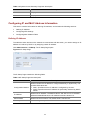
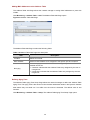
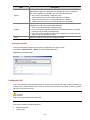
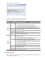
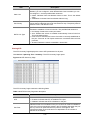
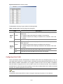
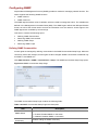
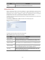
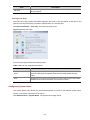
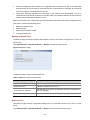
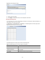
Defining IP Address
To enable the other devices on the network to communicate with the switch, you need to assign an IP
address to it: either by DHCP or by assigning a static IP address.
Click Administration > IP Setup. The IP Setup Page opens.
Figure 3-5 IP Setup Page
The IP Setup Page contains the following fields:
Table 3-4 IP Setup Page item description
Item
Description
Defines whether the IP address is configured statically or dynamically. The
possible field values are:
Configuration Method
z
z
Static: Specifies that the IP address is configured by the user.
DHCP: Specifies that the IP address is dynamically obtained by DHCP
Server.
IP Address
Defines the IP address. The default value is 169.254.xxx.xxx. If the MAC
address is 08004E000102, the IP address would be 169.254.1.2.
Subnet Mask
Defines the subnet mask. The default value is 255.255.0.0.
Gateway
Defines the gateway address. The default value is blank.
3-4
Configuring ARP Settings
The Address Resolution Protocol (ARP) converts IP addresses into physical addresses, and maps the
IP address to a MAC address. ARP allows a host to communicate with other hosts when only the IP
addresses of its neighbors are known.
This section includes the following topics:
z
Defining ARP Settings
z
Removing ARP Entries
z
Viewing ARP Settings
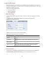
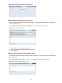
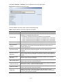
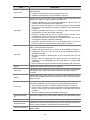
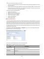
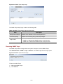
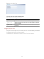
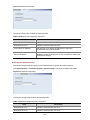
Defining ARP Settings
The ARP Settings Setup Page allows network managers to define ARP parameters for specific
interfaces.
Click Administration > ARP Settings > Setup. The ARP Settings Setup Page opens.
Figure 3-6 ARP Settings Setup Page
The ARP Settings Setup Page contains the following fields:
Table 3-5 ARP Settings Setup Page item description
Item
Description
Interface
Indicates the management VLAN (VLAN 1) for which ARP parameters are
defined.
IP Address
Defines the static IP address, which is associated with the static MAC
address.
MAC Address
Defines the static MAC address, which is associated with the static IP
address.
ARP Entry Age Out
Specifies the aging time for dynamic ARP entries. After the ARP Entry
Age, dynamic ARP entries are deleted from the table. The range is
1-40000000. The default value is 1200 seconds.
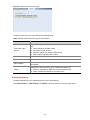
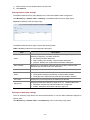
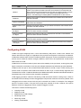
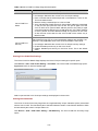
Removing ARP Entries
The ARP Entries Remove Page provides parameters for removing ARP entries from the ARP Table.
Click Administration > ARP Settings > Remove. The ARP Entries Remove Page opens.
3-5
Figure 3-7 ARP Entries Remove Page
The ARP Entries Remove Page contains the following fields:
Table 3-6 ARP Entries Remove Page item description
Item
Description
Specifies the types of ARP entries that are cleared. The possible values
are:
Clear ARP Table
Entries
z
z
z
z
None: Maintains the ARP entries.
All: Clears all ARP entries.
Dynamic: Clears only dynamic ARP entries.
Static: Clears only static ARP entries.
Interface
Indicates the VLAN for which ARP parameters are defined.
IP Address
Indicates the IP address which is associated with the MAC address.
MAC Address
Displays the MAC address, which is associated in the ARP table with the
IP address.
Displays the ARP table entry type. Possible field values are:
Status
z
z
Dynamic: Indicates the ARP entry is learned dynamically.
Static: Indicates the ARP entry is a static entry.
Viewing ARP Settings
The ARP Settings Summary Page displays the current ARP settings.
Click Administration > ARP Settings > Summary. The ARP Settings Summary Page opens.
3-6
Figure 3-8 ARP Settings Summary Page
The ARP Settings Summary Page contains the following fields:
Table 3-7 ARP Settings Summary Page item description
Item
Description
Interface
Indicates the VLAN for which ARP parameters are defined.
IP Address
Indicates the IP address, which is associated with the MAC Address.
MAC Address
Displays the station MAC address, which is associated in the ARP table
with the IP address.
Displays the ARP table entry type. Possible field values are:
Status
z
z
Dynamic: Indicates the ARP entry is learned dynamically.
Static: Indicates the ARP entry is a static entry.
Configuring MAC Address Table
MAC addresses are stored in either the static address or the dynamic address databases. A packet
addressed to a destination stored in one of the databases is forwarded immediately to the port.
The Dynamic Address Table can be sorted by interface, VLAN, and MAC address. MAC addresses are
dynamically learned as packets from sources arrive at the switch. MAC addresses are associated with
ports by learning the ports from the frames source address. Frames addressed to a destination MAC
address that is not associated with any port are flooded to all ports of the relevant VLAN.
Static addresses are manually configured. In order to prevent the bridging table from overflowing,
dynamic MAC addresses, from which no traffic is seen for a certain period, are erased.
This section includes the following sections:
z
Adding MAC Addresses to the Address Table
z
Defining Aging Time
z
Removing MAC Addresses for the specific port
z
Removing MAC Addresses from the Address Table
z
Viewing Address Table Settings
z
Viewing Port Summary Settings
3-7
Adding MAC Addresses to the Address Table
The Address Table Add Page allows the network manager to assign MAC addresses to ports with
VLANs.
Click Monitoring > Address Table > Add. The Address Table Add Page opens.
Figure 3-9 Address Table Add Page
The Address Table Add Page contains the following fields:
Table 3-8 Address Table Add Page item description
Item
Description
VLAN ID
Selects a VLAN ID.
MAC Address
Defines a MAC address to be assigned to the specific port and VLAN ID.
Marks the aging status of the MAC address assigned by the user. The
possible values are:
No Aging
z
z
Checked: Indicates that the Address Table entry assigned by the user is
not aged out.
Unchecked: Indicates that the Address Table entry assigned by the user
is aged out.
Defining Aging Time
The Address Table Aging Time Setup Page allows the network manager to define the Address Table
Aging Time. The Aging Time is the amount of time the MAC addresses remain in the Dynamic Address
table before they are timed out if no traffic from the source is detected. The default value is 300
seconds.
Click Monitoring > Address Table > Setup. The Address Table Aging Time Setup Page opens.
3-8
Figure 3-10 Address Table Aging Time Setup Page
Removing MAC Addresses for the specific port
The Port Remove Page allows the network manager to remove MAC Addresses for the specific port
from the Address Table.
Click Monitoring > Address Table > Port Remove. The Port Remove Page opens.
Figure 3-11 Port Remove Page
1)
Select a port to remove MAC Addresses.
2)
Select entries from the address table to be removed.
3)
Click Remove.
Removing MAC Addresses from the Address Table
The Address Table Remove Page allows the network manager to remove current MAC addresses from
the Address Table.
Click Monitoring > Address Table > Remove. The Address Table Remove Page opens.
Figure 3-12 Address Table Remove Page
3-9
1)
Select entries from the address table to be removed.
2)
Click Remove.
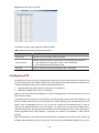
Viewing Address Table Settings
The Address Table Summary Page displays the current MAC address table configuration.
Click Monitoring > Address Table > Summary. The Address Table Summary Page opens.
Figure 3-13 Address Table Summary Page
The Address Table Summary Page contains the following fields:
Table 3-9 Address Table Summary Page item description
Item
Description
Filters the list of MAC addresses displayed according to the type of MAC
address configuration. Possible values are:
State
z
z
z
All: Displays all MAC addresses.
Static: Displays the statically configured MAC addresses.
Dynamic: Displays the dynamically learned MAC addresses.
MAC Address
Displays the current MAC addresses listed in the MAC address table,
filtered by the selected value of the State field.
VLAN ID
Displays the VLAN ID associated with the port and MAC address.
Displays the MAC address configuration method. Possible values are:
State
z
z
Port Index
Config Static: Displays the statically configured MAC address.
Config Dynamic: Displays the dynamically learned MAC address.
Displays the port through which the address was learned.
Displays that the MAC address is aged out or not.. Possible values are:
Aging Time
z
z
NOAGED: Indicates that the MAC address is not aged out.
AGING: Indicates that the MAC address is aged out.
Viewing Port Summary Settings
The Port Summary Page allows the network administrator to view the MAC addresses assigned to
specific ports.
Click Monitoring > Address Table > Port Summary. The Port Summary Page opens.
3-10
Figure 3-14 Port Summary Page
The Port Summary Page contains the following fields:
Table 3-10 Port Summary Page item description
Item
Description
Filters the list of MAC addresses displayed according to the type of MAC
address configuration. Possible values are:
State
z
z
z
All: Displays all MAC addresses.
Static: Displays the statically configured MAC addresses.
Dynamic: Displays the dynamically learned MAC addresses.
MAC Address
Displays the current MAC addresses listed in the MAC address table,
filtered by the selected value of the State field.
VLAN ID
Displays the VLAN ID associated with the port and MAC address.
State
z
Displays the MAC address configuration method. Possible values are:
z
Port Index
Config Static: Displays the statically configured MAC address.
Config Dynamic: Displays the dynamically learned MAC address.
Displays the port through which the address was learned.
Displays that the MAC address is aged out or not.. Possible values are:
Aging Time
z
z
NOAGED: Indicates that the MAC address is not aged out.
AGING: Indicates that the MAC address is aged out.
Configuring Port
This section includes the following topics:
z
Configuring Port Basic Settings
z
Configuring PoE
z
Viewing Port Statistics
Configuring Port Basic Settings
This section contains information for configuring Port Basic Settings, and includes the following topics:
z
Defining Port Settings
z
Viewing Port Settings
z
Viewing Port Details
3-11
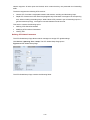
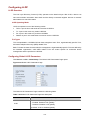
Defining Port Settings
The Port Setup Page allows network managers to configure port parameters for specific ports.
Click Port > Administration > Setup. The Port Setup Page opens.
Figure 3-15 Port Setup Page
The Port Setup Page contains the following fields:
Table 3-11 Port Setup Page item description
Item
Description
Enables and disables the port. The possible field values are:
Port State
z
z
z
Flow Control
No Change: Retains the current port status.
Enabled: Enables the port.
Disabled: Disables the port.
Enables and disables flow control on the port. When flow control is enabled
for the port, the switch regulates the packet flow so that a sending device
does not transmit more packets than a receiving device can process. If flow
control is disabled, packets may be dropped under certain periods of high
traffic. The possible values are:
z
z
z
No Change: Retains the current flow control status on the port.
Enabled: Enables flow control on the port.
Disabled: Disables flow control on the port.
Specifies the configured rate for the port. The port speed determines what
speed setting options are available. Port speeds can only be configured
when auto-negotiation is disabled. The possible field values are:
Speed
z
z
z
z
z
No Change: Retains the current port speed.
Auto: Use to automatically configure the port.
10: Indicates the port is currently operating at 10 Mbps.
100: Indicates the port is currently operating at 100 Mbps.
1000: Indicates the port is currently operating at 1000 Mbps.
Specifies the port duplex mode. The possible field values are:
z
z
Duplex
z
z
No Change: Retains the current port duplex mode.
Auto: Use to automatically configure the port.
Full: The interface supports transmission between the switch and its link
partner in both directions simultaneously.
Half: The interface supports transmission between the switch and its link
partner in only one direction at a time.
3-12
z
Before manually setting a port to full-duplex mode, verify that the device connected to the port is
also manually set to the same speed and duplex setting. If connecting link partners are left to autonegotiate for a link manually set on this switch to full-duplex, they will always negotiate to
half-duplex, resulting in a duplex mismatch. This can result in a significant reduction in network
performance. If you are unsure of how to configure the speed/duplex setting, simply enable autonegotiation for the port.
z
1000 Mbps connections are always full-duplex. Half-duplex connections are only available for 10
Mbps and 100 Mbps settings.
Viewing Port Settings
The Port Summary Page permits the network manager to view the current configuration for all the ports.
Click Port > Administration > Summary. The Port Summary Page opens.
Figure 3-16 Port Summary Page
The Port Summary Page contains the following fields:
Table 3-12 Port Summary Page item description
Item
State
Description
Indicates whether the port is currently operational or non-operational. The
possible field values are:
z
z
Enabled: Indicates the port is currently operating.
Disabled: Indicates the port is currently not operating.
Displays the flow control status on the port. The possible field values are:
Flow Control
z
z
Enabled: Enables flow control on the port.
Disabled: Disables flow control on the port.
3-13
Item
Description
Displays the configured rate for the port. The port type determines what
speed setting options are available. Port speeds can only be configured
when auto negotiation is disabled. The possible field values are:
Speed
z
z
z
z
Auto: Use to automatically configure the port.
10M: Indicates the port is currently operating at 10 Mbps.
100M: Indicates the port is currently operating at 100 Mbps.
1000M: Indicates the port is currently operating at 1000 Mbps.
Displays the port duplex mode. The port speed is set to 10M or 100M or
1000M per second. The possible field values are:
z
Duplex
z
z
PVID
Auto: Use to automatically configure the port.
Full: The interface supports transmission between the switch and its link
partner in both directions simultaneously.
Half: The interface supports transmission between the switch and the
client in only one direction at a time.
Indicates VLAN ID of this port for untagged packets.
Viewing Port Details
The Port Detail Page displays the current port configuration for specific ports.
Click Port > Administration > Detail. The Port Detail Page opens.
Figure 3-17 Port Detail Page
Configuring PoE
Power over Ethernet (PoE) provides power to devices over existing LAN cabling, without updating or
modifying the network infrastructure. Power over Ethernet removes the necessity of placing network
devices next to power sources.
PoE is only supported by 2426-PWR Plus.
This section contains the following topics:
z
Defining Port PoE
z
Viewing PoE
3-14
Defining Port PoE
The Port PoE Setup Page allows the network manager to configure port PoE settings.
Click Port > PoE > Setup. The Port PoE Setup Page opens.
Figure 3-18 Port PoE Setup Page
The Port PoE Setup Page contains the following fields:
Table 3-13 Port PoE Setup Page item description
Item
Description
Defines the port PoE state. The possible values are:
PoE State
z
z
PoE Mode for selected
& enabled ports
Enable: Enables the port for PoE.
Disable: Disables the port for PoE.
Defines the PoE mode for the selected port.
Displays guaranteed and total PoE power:
z
z
Guarantee Power
Summary
z
Selected Ports
Total PoE Available: The total amount of PoE power that can be
provided by the switch.
Guarantee PoE: The maximum amount of PoE power that has been
guaranteed for selected ports. This value is defined by the number of
ports you have set to Guarantee.
Remaining (Available - Guarantee): The minimum amount of
non-guaranteed PoE power left over after allocating the Guarantee
PoE power. This value is a guideline for assigning guarantee ports. The
actual amount of power used and available is displayed on the Port
PoE Summary page.
Displays the PoE configuration for the selected ports.
Viewing PoE
The Port PoE Summary Page displays the switch and port PoE settings.
Click Port > PoE. The PoE Summary Page opens.
3-15
Figure 3-19 Port PoE Summary Page
The Port PoE Summary Page contains the following fields:
Table 3-14 Port PoE Summary Page item description
Item
Description
Indicates the power source status. The possible field values are:
z
State
z
z
Device
Power
Display
On: Indicates that the power supply unit is functioning.
Off: Indicates that the power supply unit is not functioning.
Faulty: Indicates that the power supply unit is functioning, but an error
has occurred. For example, a power overload or a short circuit.
Power
Max(watts)
Indicates the maximum amount of power the switch can supply. The field
value is displayed in Watts.
Power
Used(watts)
Indicates the actual amount of power currently used by the switch. The field
value is displayed in Watts.
Power
Free(watts)
Indicates the amount of additional power currently available to the switch.
The field value is displayed in Watts.
State
Indicates if the port is enabled to deliver power to powered devices. The
possible field values are:
z
z
Enable: Indicates the switch is delivering power. This is the default.
Disabled: Indicates the switch is not delivering power.
Indicates the port power mode. The possible field values are:
z
Ports
Power
Display
Mode
z
Auto: Power is automatically allocated to the port, according to port
number. Lower numbered ports are assigned a higher priority for power
delivery. This is the default.
Guarantee: Power is guaranteed to the selected port, provided that the
power is available. This setting overrides the priority assigned to lower
port numbers by the auto mode.
Power
Max(watts)
Indicates the maximum amount of power available to the interface. The field
value is displayed in Watts.
Power
Used(watts)
Indicates the actual amount of power currently used by the interface. The
field value is displayed in Watts.
Viewing Port Statistics
The Port Statistics Summary Page contains fields for viewing information about switch utilization and
errors that occurred on the switch.
3-16
Click Port > Statistics > Summary. The Port Statistics Summary Page opens.
Figure 3-20 Port Statistics Summary Page
The Port Statistics Summary Page contains the following fields:
Table 3-15 Port Statistics Summary Page item description
Item
Description
Defines the amount of time that passes before the interface statistics are
refreshed. The possible field values are:
Refresh Rate
z
z
z
z
No Refresh: Indicates that the port statistics are not refreshed.
15 Sec: Indicates that the port statistics are refreshed every 15 seconds.
30 Sec: Indicates that the port statistics are refreshed every 30 seconds.
60 Sec: Indicates that the port statistics are refreshed every 60 seconds.
Clear All Counters
Clears the port statistics counters and the new statistics are displayed.
Received Bytes
(Octets)
Displays the number of octets received on the interface since the switch was
last refreshed. This number includes bad packets and FCS octets, but
excludes framing bits.
Received Packets
Displays the number of packets received on the interface, including bad
packets, Multicast and broadcast packets, since the switch was last
refreshed.
Broadcast Packets
Received
Displays the number of good broadcast packets received on the interface
since the switch was last refreshed. This number does not include Multicast
packets.
Multicast Packets
Received
Displays the number of good Multicast packets received on the interface
since the switch was last refreshed.
CRC & Align Errors
Displays the number of CRC and Align errors that have occurred on the
interface since the switch was last refreshed.
Undersize Packets
Displays the number of undersized packets (less than 64 octets) received on
the interface since the switch was last refreshed.
Oversize Packets
Displays the number of oversized packets (over 9216 octets) received on the
interface since the switch was last refreshed.
Fragments
Displays the number of fragments (packets with less than 64 octets,
excluding framing bits, but including FCS octets) received on the interface
since the switch was last refreshed
3-17
Item
Description
Jabbers
Displays the total number of received packets that were longer than 9216
octets. This number excludes frame bits, but includes FCS octets that had
either a bad Frame Check Sequence (FCS) with an integral number of octets
(FCS Error) or a bad FCS with a non-integral octet (Alignment Error)
number. The field range to detect jabbers is between 20 ms and 150 ms.
Collisions
Displays the number of collisions received on the interface since the switch
was last refreshed.
Frames of 64 Bytes
Displays the number of 64-byte frames received on the interface since the
switch was last refreshed.
Frames of 65 to 127
Bytes
Displays the number of 65 to 127 byte frames received on the interface since
the switch was last refreshed
Frames of 128 to
255 Bytes
Displays the number of 128 to 255 byte frames received on the interface
since the switch was last refreshed.
Frames of 256 to
511 Bytes
Displays the number of 256 to 511 byte frames received on the interface
since the switch was last refreshed.
Frames of 512 to
1023 Bytes
Displays the number of 512 to 1023 byte frames received on the interface
since the switch was last refreshed.
Frames of 1024 to
1522 Bytes
Displays the number of 1024 to 1522 byte frames received on the interface
since the switch was last refreshed.
Configuring VLAN
VLANs are logical subgroups with a Local Area Network (LAN) which combine user stations and
network devices into a single unit, regardless of the physical LAN segment to which they are attached.
VLANs allow network traffic to flow more efficiently within subgroups. VLANs use software to reduce the
amount of time it takes for network changes, additions, and moves to be implemented. VLANs restrict
traffic within the VLAN.
VLANs have no minimum number of ports, and can be created per unit, per device, or through any other
logical connection combination, since they are software-based and not defined by physical attributes.
VLANs function at Layer 2. Since VLANs isolate traffic within the VLAN, a Layer 3 router working at a
protocol level is required to allow traffic flow between VLANs. Layer 3 routers identify segments and
coordinate with VLANs. VLANs are Broadcast and Multicast domains. Broadcast and Multicast traffic is
transmitted only in the VLAN in which the traffic is generated.
VLAN tagging provides a method of transferring VLAN information between VLAN groups. VLAN1 is
the default VLAN and always contains untagged ports. All ports are members of VLAN1 by default. If the
untagged port is moved to a new VLAN, the port is removed from VLAN1. For example: If an untagged
port 24 is moved to VLAN 5. The port will no longer be a member of VLAN1. However, if the port is
added to VLAN5 as a tagged port it then remains untagged in VLAN1.
This section contains the following topics:
z
Creating VLANs
z
Modifying VLAN
z
Modifying Port VLAN Settings
z
Renaming VLANs
z
Removing VLANs
z
Viewing VLAN Details
3-18
Viewing VLAN Port Details
z
Creating VLANs
The VLAN Setup Page allows the network administrator to create or rename VLANs.
Click Device > VLAN > Setup. The VLAN Setup Page opens.
Figure 3-21 VLAN Setup Page
The VLAN Setup Page contains the following fields:
Table 3-16 VLAN Setup Page item description
Item
Description
Create VLANs
Enter ID of configured VLANs.
Create
Creates the VLAN ID(s).
ID
Displays the VLAN ID.
Name
Displays the user-defined VLAN name.
Modifying VLAN
The Modify VLAN Page allows the network manager to change VLAN membership.
At least one port must always be an untagged member of VLAN 1 (the management VLAN). If you
choose to connect all ports to VLANs other than VLAN 1, you will no longer be able to access the Web
interface. If this happens, you will need to reset the switch to factory settings.
Click Device > VLAN > Modify VLAN. The Modify VLAN Page opens.
3-19
Figure 3-22 Modify VLAN Page
The Modify VLAN Page contains the following fields:
Table 3-17 Modify VLAN Page item description
Item
Select a VLAN to
modify
Description
Selects a VLAN to modify its settings.
Selects the membership type for each port on the VLAN. The possible field
values are:
z
Select membership
type
z
z
z
Untagged: Indicates the interface is an untagged member of the VLAN.
Tagged: Indicates the interface is a tagged member of a VLAN. VLAN
tagged frames are forwarded by the interface. The frames contain VLAN
information.
Not A Member: Indicates the interface is not a member of the VLAN.
Not available for selection: Indicates the interface is not available for
selection.
Untagged
membership
Indicates the port is an untagged member of the VLAN.
Tagged membership
Indicates the port is a tagged member of a VLAN. VLAN tagged frames are
forwarded by the interface. The frames contain VLAN information.
By default, all ports belong to VLAN 1 as an untagged member. However, they can belong to multiple
VLANs as a tagged member. Also, newly created VLANs will initially have no ports associated with
them.
Modifying Port VLAN Settings
The Modify Port VLAN Page allows the network manager to modify port VLAN settings.
Click Device > VLAN > Modify Port. The Modify Port VLAN Page opens.
3-20
Figure 3-23 Modify Port VLAN Page
The Modify Port VLAN Page contains the following fields:
Table 3-18 Modify Port VLAN Page item description
Item
Description
Selects the membership type for each port on the VLAN. The possible field
values are:
z
Select membership
type
z
z
z
VLAN ID
Untagged: Indicates the interface is an untagged member of the VLAN.
Tagged: Indicates the interface is a tagged member of a VLAN. VLAN
tagged frames are forwarded by the interface. The frames contain VLAN
information.
Not A Member: Indicates the interface is not a member of the VLAN.
Not available for selection: Indicates the interface is not available for
selection.
Defines the VLAN ID to which the port is to be assigned.
Renaming VLANs
The VLAN Rename Page allows the network manager to select a VLAN from the list to be renamed.
Click Device > VLAN > Rename. The VLAN Rename Page opens.
Figure 3-24 VLAN Rename Page
Removing VLANs
The VLAN Remove Page allows the network administrator to remove VLANs.
Click Device > VLAN > Remove. The VLAN Remove Page opens.
3-21
Figure 3-25 VLAN Remove Page
Viewing VLAN Details
The VLAN Detail Page provides information and global parameters on VLANs configured on the
system.
Click Device > VLAN > VLAN Detail. The VLAN Detail Page opens.
Figure 3-26 VLAN Detail Page
The VLAN Detail Page contains the following information:
3-22
Table 3-19 VLAN Detail Page item description
Item
Select a VLAN to
Display
Description
Selects a VLAN to be display its settings
Displays the membership type for each VLAN. The possible field values are:
z
z
z
Untagged: Indicates the interface is an untagged member of the VLAN.
Tagged: Indicates the interface is a tagged member of a VLAN. VLAN
tagged frames are forwarded by the interface. The frames contain VLAN
information.
Not A Member: Indicates the interface is not a member of the VLAN
Each port on the switch is capable of passing tagged or untagged frames.
The following describes how the switch will handle tagged and untagged
frames.
z
Membership type
z
When a port receives a tagged frame with a VLAN ID and the port is a
member (untagged or tagged) of that VLAN, the frame is accepted.
Otherwise if the port is not a member of that VLAN, the frame is
discarded.
When a port receives an untagged frame and the port is an untagged
member of a VLAN, the frame is accepted and assigned to that VLAN ID.
Otherwise if the port is not an untagged member of any VLAN, the frame
is discarded.
The switch will only forward a frame to ports that are members (tagged or
untagged) of the VLAN to which the frame is assigned. If the port is an
untagged member, the egress frame will be stripped of the VLAN tag and
forwarded as untagged. However, if the port is a tagged member, the egress
frame is forwarded as tagged.
Viewing VLAN Port Details
The VLAN Port Detail Page provides information on VLAN configured ports.
Click Device > VLAN > Port Detail. The VLAN Port Detail Page opens.
Figure 3-27 VLAN Port Detail Page
The VLAN Port Detail Page contains the following information:
3-23
Table 3-20 VLAN Port Detail Page item description
Item
Description
Untagged
Membership
Indicates the port is an untagged member of the VLAN.
Tagged membership
Indicates the port is a tagged member of a VLAN. VLAN tagged frames are
forwarded by the interface. The frames contain VLAN information.
Aggregating Port
Overview
Link aggregation aggregates multiple physical Ethernet ports into one logical link, called a Link
Aggregation Group (LAG).
It allows you to increase bandwidth by distributing traffic across the member ports in the aggregation
group. In addition, it provides reliable connectivity because these member ports can dynamically back
up each other.
LACP
Link Aggregation Control Protocol (LACP) based on the IEEE802.3ad standard can be used for
dynamic link aggregation. An LACP-enabled port sends link aggregation control protocol data units
(LACPDUs) to tell the peer about its system priority, system MAC address, port priority, port number and
operation key. After receiving the information from the sender, the receiver compares it with the locally
saved information about other ports, chooses member ports for the aggregation group and reaches
agreement about whether a port can join or leave a dynamic aggregation group.
During link aggregation, LACP generates a configuration mix according to the port configuration (rate,
duplex, basic configuration, management key), which is called an operation key.
Link Aggregation Types
The switch supports two link aggregation types:
z
Manual Aggregation
z
Static LACP Aggregation
1)
Manual Aggregation
Manual aggregation is configured manually, and cannot be added or removed automatically. A manual
or static LACP aggregation group must contain at least a member port. Member ports in a manual
aggregation are LACP-disabled.
A port in a manual aggregation group can be in one of the two states: selected or unselected. In a
manual aggregation group, only the selected ports can forward user service packets.
In a manual aggregation group, the system sets the ports to selected or unselected state according to
the following rules.
3-24
z
Among the ports in an aggregation group that are in up state, the system determines the mater port
with one of the following settings being the highest (in descending order) as the master port: full
duplex/high speed, full duplex/low speed, half duplex/high speed, half duplex/low speed. The ports
with their rate, duplex mode and link type being the same as that of the master port are selected
ports, and the rest are unselected ports.
z
There is a limit on the number of selected ports in an aggregation group. Therefore, if the number of
the selected ports in an aggregation group exceeds the maximum number supported by the switch,
those with lower port numbers operate as the selected ports, and others as unselected ports.
Among the selected ports in an aggregation group, the one with smallest port number operates as the
master port. Other selected ports are the member ports.
2)
Static LACP Aggregation
A static LACP aggregation group is also manually created. All its member ports are manually added and
can be manually removed (it inhibits the system from automatically adding/removing ports to/from it).
LACP is enabled on the member ports of static aggregation groups. When you remove a static
aggregation group, all the member ports in up state form one or multiple dynamic aggregations with
LACP enabled.
A port in a static aggregation group can be in one of the two states: selected or unselected.
z
Both the selected and the unselected ports in the up state can receive/send LACP protocol
packets.
z
Only the selected ports can receive/send service packets; the unselected ports cannot.
In a static aggregation group, the system sets the ports to selected or unselected state according to the
following rules.
z
Among the ports in an aggregation group that are in up state, the system determines the master
port with one of the following settings being the highest (in descending order) as the master port:
full duplex/high speed, full duplex/low speed, half duplex/high speed, half duplex/low speed. The
ports with their rate, duplex mode and link type being the same as that of the master port are
selected port, and the rest are unselected ports.
z
The ports connected to a peer device different from the one the master port is connected to, or
those connected to the same peer device as the master port but to a peer port that is not in the
same aggregation group as the peer port of the master port, are unselected ports.
z
The system sets the ports with basic port configuration different from that of the master port to
unselected state.
z
There is a limit on the number of selected ports in an aggregation group. Therefore, if the number of
the selected ports in an aggregation group exceeds the maximum number supported by the switch,
those with lower port numbers operate as the selected ports, and others as unselected ports.
Configuring Link Aggregation
This section includes the following topics:
z
Defining Link Aggregation
z
Modifying Link Aggregation
z
Removing Link Aggregation
z
Viewing Link Aggregation
Defining Link Aggregation
The Link Aggregation Create Page allows network managers to create LAGs and add ports to a LAG.
3-25
Click Port > Link Aggregation > Create. The Link Aggregation Create Page opens.
Figure 3-28 Link Aggregation Create Page
The Link Aggregation Create Page includes the following fields:
Table 3-21 Link Aggregation Create Page item description
Item
Description
Enter Aggregation
Group ID
Defines the group ID.
Manual
Defines Manual Aggregation
Static
Defines Static LACP Aggregation
To create a new link aggregation group:
1)
Enter a LAG ID in the box field.
2)
Select Link Aggregation Type (Manual or Static)
3)
Select the ports to add to the group.
4)
Click Apply.
Modifying Link Aggregation
The Link Aggregation Modify Page allows network managers to select or deselect port for the specific
LAG.
Click Port > Link Aggregation > Modify. The Link Aggregation Modify Page opens.
3-26
Figure 3-29 Link Aggregation Modify Page
Removing Link Aggregation
The Link Aggregation Remove Page allows the network manager to remove group IDs containing
member ports.
Click Port > Link Aggregation > Remove. The Link Aggregation Remove Page opens.
Figure 3-30 Link Aggregation Remove Page
Viewing Link Aggregation
The Link Aggregation Summary Page displays the state of the current link aggregation.
Click Port > Link Aggregation > Summary. The Link Aggregation Summary Page opens.
Figure 3-31 Link Aggregation Summary Page
The Link Aggregation Summary Page includes the following fields:
3-27
Table 3-22 Link Aggregation Summary Page item description
Item
Description
Group ID
Displays the Link Aggregated Group ID. The field range is 1-6.
Type
Displays the type of link aggregation for the Group ID. The possible field
value is Static or LACP.
Ports
Displays the member ports included in the specified LAG.
Configuring LACP
This section includes the following topics:
z
Modify LACP
z
Viewing LACP
Modify LACP
The Link Aggregation Modify Page allows the network manager to modify fields for LACP.
Click Port > Link Aggregation > Modify. The Link Aggregation Modify Page opens.
Figure 3-32 Link Aggregation Modify Page
The Link Aggregation Modify Page contains the following fields:
Table 3-23 Link Aggregation Modify Page item description
Item
Description
LACP System
Priority
Specifies system priority value. The default value is 32768. The field range is
0-65535.
LACP Port Priority
Specifies the LACP priority value for the port. The default is 32768. The field
range is 0-65535.
Selects the administrative LACP timeout. The possible field values are:
LACP Timeout
z
z
Long: Specifies the long timeout value. This is the default.
Short: Specifies the short timeout value.
Viewing LACP
The LACP Summary Page displays fields for LACP.
Click Port > Link Aggregation > LACP. The LACP Summary Page opens.
3-28
Figure 3-33 LACP Summary Page
The LACP Summary Page contains the following fields:
Table 3-24 LACP Summary Page item description
Item
Port-Priority
Description
Displays the LACP priority value for the port.
Displays the administrative LACP timeout. The possible field values are:
LACP Timeout
z
z
Group ID
Long: Specifies the long timeout value. This is the default.
Short: Specifies the short timeout value.
Display LAG ID which the port belongs to. N/A: unassigned.
Configuring STP
STP (Spanning Tree Protocol) is a bridge-based system for providing fault tolerance on networks and
can be used to detect and disable network loops. The spanning tree ensures that the optimal path is
maintained between spanning tree-compliant networked devices by:
z
Disabling redundant paths when the main paths are operational.
z
Enabling redundant paths if the main paths fail.
Spanning tree uses a distributed algorithm to select a bridging device that serves as the root of the
spanning tree network.
The bridging device, known as the Root Bridge, generates bridge protocol data units (BPDUs) on all
ports at a regular interval known as the Hello Time. All other spanning tree-compliant devices on the
network have a designated Root Port. This is the Port nearest the Root Bridge and it is used for
receiving the BPDUs initiated by the Root Bridge. If a bridge does not get a Hello BPDU after a
predetermined interval, the bridge assumes that the link to the Root Bridge is down. This bridge will then
initiate negotiations with other bridges to reconfigure the network to reestablish a valid network
topology.
After all the bridges on the network have determined the configuration of their ports, each bridge only
forwards traffic between the Root Port and the ports that are the Designated Bridge Ports for each
3-29
network segment. All other ports are blocked, which means that they are prevented from forwarding
traffic.
The device supports the following STP versions:
z
Classic STP: Provides a single path between end stations, avoiding and eliminating loops.
z
Rapid STP: Detects and uses network topologies that provide faster convergence of the spanning
tree, without creating forwarding loops. While Classic STP prevents Layer 2 forwarding loops in a
general network topology, convergence can take between 30-60 seconds.
This section contains the following topics:
z
Defining STP Global Parameters
z
Modifying STP Interface Parameters
z
Viewing STP
Defining STP Global Parameters
The STP Global Setup Page allows network managers to assign STP global settings.
Click Device > Spanning Tree > Setup. The STP Global Setup Page opens.
Figure 3-34 STP Global Setup Page
The STP Global Setup Page contains the following fields:
3-30
Table 3-25 STP Global Setup Page item description
Item
Spanning Tree
State
Description
Defines whether STP is enabled on the switch. The possible field
values are:
z
z
z
Global
Settings
BPDU
Handling
Disable: Disables STP and RSTP on the switch.
Classic: Enables STP on the switch.
RSTP: Enables RSTP on the switch.
Determines how BPDU packets are managed when STP is
disabled on the port or switch. BPDUs are used to transmit
spanning tree information. The possible field values are:
z
z
Filtering: Filters BPDU packets when spanning tree is disabled
on an interface.
Flooding: Floods BPDU packets when spanning tree is
disabled on an interface. This is the default value.
Specifies the method used to assign default path cost to STP
ports. The possible field values are:
z
Path Cost
Default Values
Priority
Specifies the bridge priority value. When switches or bridges are
running STP, each is assigned a priority. After exchanging
BPDUs, the switch with the lowest priority value becomes the Root
Bridge. The field range is 0-61440. The default value is 32768. The
port priority value is provided in increments of 4096.
Hello Time
Specifies the switch Hello Time. The Hello Time indicates the
amount of time in seconds a Root Bridge waits between
configuration messages. The default is 2 seconds.
Max Age
Specifies the switch Maximum Age Time. The Maximum Age Time
is the amount of time in seconds a bridge waits before sending
configuration messages. The default Maximum Age Time is 20
seconds.
Forward Delay
Specifies the switch Forward Delay Time. The Forward Delay
Time is the amount of time in seconds a bridge remains in a
listening and learning state before forwarding packets. The default
is 15 seconds.
Bridge ID
Identifies the Bridge priority and MAC address.
Root Bridge ID
Identifies the Root Bridge priority and MAC address.
Root Port
Indicates the port number that offers the lowest cost path from this
bridge to the Root Bridge. This field is significant when the bridge
is not the Root Bridge. The default is zero.
Root Path Cost
Indicates the cost of the path from this bridge to the Root Bridge.
Topology
Changes
Counts
Indicates the total amount of STP state changes that have
occurred.
Last Topology
Change
Indicates the amount of time that has elapsed since the bridge was
initialized or reset, and the last topographic change that occurred.
The time is displayed in a day-hour-minute-second format, such as
2 days 5 hours 10 minutes and 4 seconds.
Bridge
Settings
Designated
Root
z
Short: Specifies 1 through 65535 ranges for port path cost. This
is the default value.
Long: Specifies 1 through 200000000 ranges for port path cost.
The default path cost assigned to an interface varies according
to the selected method (Hello Time, Max Age, or Forward
Delay).
3-31
Modifying STP Interface Parameters
The STP Interface Parameters Modify Page allows network managers to modify STP parameters to
specific interfaces.
Click Device > Spanning Tree > Modify. The STP Interface Parameters Modify Page opens.
Figure 3-35 STP Interface Parameters Modify Page
The STP Interface Parameters Modify Page contains the following fields:
Table 3-26 STP Interface Parameters Modify Page item description
Item
Description
Specifies if STP is enabled on the port. The possible field values are:
z
STP
z
z
Port Fast
No Change: Retains the current port status.
Enabled: Indicates that STP is enabled on the port.
Disabled: Indicates that STP is disabled on the port. This is the default
value.
Specifies if Fast Link is enabled on the port. If Fast Link mode is enabled for
a port, the port is automatically placed in the Forwarding state when the port
link is up. Fast Link optimizes the STP protocol convergence. STP
convergence takes 30 seconds and is not dependent on the number of
switches in the network. The possible field values are:
z
z
z
No Change: Retains the current port status.
Enabled: Indicates fast link is enabled on the port.
Disabled: Indicates fast link is disabled on the port. This is the default
value.
Restricts the interface from acting as the root port of the switch. The possible
field values are:
Root Guard
z
z
z
No Change: Retains the current port status.
Enabled: Indicates Root Guard is enabled on the port.
Disabled: Indicates Root Guard is disabled on the port. This is the default
value.
Specifies if Default Path Cost is enabled. The possible field values are:
z
Default Path Cost
z
z
No Change: Retains the current port status.
Enabled: Enables the default path cost on the port. This is the default
value.
Disabled: Disables the default path cost on the port.
3-32
Item
Path Cost
Description
Defines the port contribution to the root path cost. When Default Path Cost is
disabled, you can configure it; when Default Path Cost is enabled, you can
not configure it , and the possible field values are:
z
z
Port Priority
65535: Indicates Path Cost Default Values is short. This is the default
value.
200000000: Indicates Path Cost Default Value is long.
Defines the priority value of the port. The priority value influences the port
choice when a bridge has two ports connected in a loop. The priority value is
between 0-240. The default is 128.
Specifies whether a Point-to-Point link is established, or if the switch is
permitted to establish a Point-to-Point link. The possible field values are:
z
z
RSTP Link Type
z
z
No Change: Retains the current port status.
Auto: Enables the switch to establish automatically Point-to-Point link.
This is the default value.
Point to Point: Indicates if a Point-to-Point link is currently established on
the port. Ports set to Full Duplex modes are considered Point-to-Point
port links.
Shared: Enables the switch to establish a shared link.
Viewing STP
The STP Summary Page displays the current STP parameters for all ports.
Click Device > Spanning Tree > Summary. The STP Summary Page opens.
Figure 3-36 STP Summary Page
The STP Summary Page contains the following fields:
Table 3-27 STP Summary Page item description
Item
Description
Indicates if STP is enabled on the port. The possible field values are:
STP
z
z
Port Fast
Enabled: Indicates that STP is enabled on the port.
Disabled: Indicates that STP is disabled on the port.
Indicates if Fast Link is enabled on the port. If Fast Link mode is enabled for
a port, the port is automatically placed in the Forwarding state when the port
link is up. Fast Link optimizes the STP protocol convergence. STP
convergence takes 30 seconds and is not dependent on the number of
switches in the network.
3-33
Item
Root Guard
Description
Indicates if the interface is acting as the root port of the switch. The possible
field values are:
z
z
Enabled: Indicates Root Guard is enabled on the port
Disabled: Indicates Root Guard is disabled on the port.
Displays the current STP state of a port. If enabled, the port state determines
what action is taken on traffic. Possible port states are:
z
z
Port State
z
z
z
z
Disable: Indicates that STP is currently disabled on the port. The port
forwards traffic while learning MAC addresses.
Blocking: Indicates that the port is currently blocked and cannot forward
traffic or learn MAC addresses. Blocking is displayed when Classic STP
is enabled.
Listening: Indicates that the port is in listening mode. The port cannot
forward traffic nor can it learn MAC addresses.
Learning: Indicates that the port is in learning mode. The port cannot
forward traffic, however it can learn new MAC addresses.
Forwarding: Indicates that the port is in forwarding mode. The port can
forward traffic and learn new MAC addresses.
Discarding: Indicates that the port is in discarding mode. The port is
listening to BPDUs, and discards any other frames it receives.
Displays the port role assigned by the STP algorithm to provide to STP
paths. The possible field values are:
z
z
Port Role
z
z
z
Disable: Indicates that the port or LAG is currently disabled on the port
Designated: The port or LAG through which the designated switch is
attached to the LAN.
Alternate: Provides an alternate path to the root switch from the root
interface.
Backup: With the designated port being blocked, the backup port
becomes the new designated port fast and begins to forward data
seamlessly.
Root: Provides the lowest cost path to forward packets to the root switch.
Speed
Indicates the speed at which the port is operating.
Path Cost
Indicates the port contribution to the root path cost. The path cost is adjusted
to a higher or lower value, and is used to forward traffic when a path is
re-routed.
Priority
Indicates the priority value of the port. The priority value influences the port
choice when a bridge has two ports connected in a loop. The priority range is
between 0-240.
Indicates whether a Point-to-Point link is established, or if the switch is
permitted to establish a Point-to-Point link. The possible field values are:
z
Link Type
z
z
Auto: Enables the switch to establish automatically point-to-point link.
Point to Point: Indicates if a point-to-point link is currently established on
the port. Ports set to Full Duplex modes are considered Point-to-Point
port links.
Shared: Enables the switch to establish a shared link.
Designated Bridge
ID
Indicates the bridge priority and the MAC Address of the designated bridge.
Designated Port ID
Indicates the selected port priority and interface.
Designated Cost
Indicates the cost of the port participating in the STP topology. Ports with a
lower cost are less likely to be blocked if STP detects loops.
Forward Transitions
Indicates the number of times the port has changed from Forwarding state to
Blocking state.
3-34
Configuring IGMP Snooping
This section contains information for configuring IGMP Snooping.
When IGMP Snooping is enabled, all IGMP packets are forwarded to the CPU. The CPU analyzes the
incoming packets and determines:
z
Which ports want to join which Multicast groups.
z
Which ports have Multicast routers generating IGMP queries.
z
Which routing protocols are forwarding packets and Multicast traffic.
Ports requesting to join a specific Multicast group issue an IGMP report, specifying that Multicast group
is accepting members. This results in the creation of the Multicast filtering database.
This section contains the following topic:
z
Defining IGMP Snooping
Defining IGMP Snooping
The IGMP Snooping Setup Page allows network managers to define IGMP Snooping parameters for
VLANs.
Click Device > IGMP Snooping > Setup. The IGMP Snooping Setup Page opens.
Figure 3-37 IGMP Snooping Setup Page
The IGMP Snooping Setup Page contains the following fields:
Table 3-28 IGMP Snooping Setup Page item description
Item
IGMP Snooping
Status
Description
Defines whether IGMP Snooping is enabled on the switch. The possible field
values are:
z
z
Enabled: Indicates that IGMP Snooping is enabled on the switch.
Disabled: Indicates that IGMP Snooping is disabled on the switch. This is
the default value.
Defines whether IGMP Query is enabled on the switch. The possible field
values are:
IGMP Query Status
z
z
Enabled: Indicates that IGMP Query is enabled on the switch.
Disabled: Indicates that IGMP Query is disabled on the switch. This is the
default value.
3-35
Item
Select VLAN ID
IGMP Snooping
Status
Description
Specifies the VLAN ID
Defines whether IGMP snooping is enabled on the VLAN. The possible field
values are:
z
z
IGMP Query Status
Enabled: Enables IGMP Snooping on the VLAN.
Disabled: Disables IGMP Snooping on the VLAN. This is the default
value.
Defines whether IGMP query is enabled on the VLAN. The possible field
values are:
z
z
Enabled: Enables IGMP Query on the VLAN.
Disabled: Disables IGMP Query on the VLAN. This is the default value.
Configuring ACL
Access Control List (ACL) allow network managers to define classification actions and rules for specific
ingress ports. A network manager can configure an ACL on an ingress port so that packets are either
admitted or denied entry. The user can also specify that when packets are denied entry, the ingress port
is also disabled.
This section includes the following topics:
z
Configuring MAC Based ACL
z
Configuring IP Based ACL
z
Configuring ACL Binding
Configuring MAC Based ACL
This section includes the following topics:
z
Defining MAC Based ACL
z
Modifying MAC Based ACL
z
Removing MAC Based ACL
z
Viewing MAC Based ACL
Defining MAC Based ACL
The MAC Based ACL Setup Page allows network managers to define MAC Based ACL.
Click Device > ACL > MAC Based ACL > Setup. The MAC Based ACL Setup Page opens.
Figure 3-38 MAC Based ACL Setup Page
The MAC Based ACL Setup Page contains the following fields:
3-36
Table 3-29 MAC Based ACL Setup Page item description
Item
Selection ACL
Description
Selects an existing MAC-based ACL to which rules are to be added.
Defines a new user-defined MAC-based Access Control List. The options
are as follows:
Create ACL
z
z
ACL Priority: Sets the ACL priority. The possible field values are 1-100.
Rule Priority Type: Sets the rule priority type. CONFIG: You will have to
configure the ACL rule priority by yourself, AUTO: the ACL rule priority
will be configured automatically.
Priority
Sets the rule priority, which determines which rule is matched to a packet on
a first-match basis. The possible field values are 1-65535.
Source MAC
Address
Matches the source MAC address to which packets are addressed to the
rule.
Defines the source MAC Address wildcard mask.
Source Mask
Wildcards are used to mask all or part of a source MAC address. Wildcard
masks specify which bits are used and which are ignored. A wildcard mask
of FF:FF:FF:FF:FF:FF indicates that no bit is important. A wildcard of
00.00.00.00.00.00.00 indicates that all bits are important.
For example, if the source MAC address is 00:AB:22:11:33:00 and the
wildcard mask is 00:00:00:00:00:FF, the first five bytes of the MAC are used,
while the last byte is ignored. For the source MAC address
00:AB:22:11:33:00, this wildcard mask matches all MAC addresses in the
range 00:AB:22:11:33:00 to 00:AB:22:11:33:FF.
Destination MAC
Address
Matches the destination MAC address to which packets are addressed to the
rule.
Defines the destination MAC Address wildcard mask.
Destination Mask
Wildcards are used to mask all or part of a destination MAC address.
Wildcard masks specify which bits are used and which are ignored. A
wildcard mask of FF:FF:FF:FF:FF:FF indicates that no bit is important. A
wildcard mask of 00.00.00.00.00.00 indicates that all bits are important.
For example, if the destination MAC address is 00:AB:22:11:33:00 and the
wildcard mask is 00:00:00:00:00:FF, the first five bytes of the MAC are used,
while the last byte is ignored. For the destination MAC address
00:AB:22:11:33:00, this wildcard mask matches all MAC addresses in the
range 00:AB:22:11:33:00 to 00:AB:22:11:33:FF.
VLAN ID
Matches the packet's VLAN ID to the rule. The possible field values are 1 to
4094.
CoS
Classifies traffic based on the CoS tag value.
CoS Mask
Defines the CoS mask used to classify network traffic.
Ethertype
Provides an identifier that differentiates between various types of protocols.
Action
Specifies the ACL forwarding action. In addition, the port can be shut down,
a trap can be sent to the network administrator, or packet is assigned rate
limiting restrictions for forwarding. The options are as follows:
z
z
Permit: Forwards packets which meet the ACL criteria.
Deny: Drops packets which meet the ACL criteria.
To create a new MAC-based ACL:
1)
Select Create ACL.
2)
Enter the name of the new ACL.
3)
Click Create. The new ACL is created, and the switch is updated.
3-37
To define a new MAC-based ACL rule:
1)
Select Selection ACL.
2)
Select the ACL from the list.
3)
Define the fields for the new ACL rule.
4)
Click Apply.
Modifying MAC Based ACL
The MAC Based ACL Modify Page allows the network administrator to modify an existing MAC-based
ACL rule.
Click Device > ACL > MAC Based ACL > Modify. The MAC Based ACL Modify Page opens.
Figure 3-39 MAC Based ACL Modify Page
The description of parameters in the page refers to Defining MAC Based ACL.
1)
Selects the ACL to be modified.
2)
Selects the Rule to be modified.
3)
Modifies the fields of the Rule.
4)
Click Apply.
Removing MAC Based ACL
The MAC Based ACL Remove Page allows the network administrator to remove MAC-based ACL or
MAC-based ACL rules.
Click Device > ACL > MAC Based ACL > Remove. The MAC Based ACL Remove Page opens.
Figure 3-40 MAC Based ACL Remove Page
The MAC Based ACL Remove Page contains the following fields:
3-38
Table 3-30 MAC Based ACL Remove Page item description
Item
Description
ACL Name
Selects a MAC-based ACL for removal.
Remove ACL
Enables the ACL to be removed.
To remove MAC-based ACL:
1)
Select the ACL Name to be removed
2)
Check Remove ACL.
3)
Click Remove.
To remove MAC-based ACL rules:
1)
Select the ACL Name containing the rules to be deleted.
2)
For each rule to be removed, check the box to the left of the row in the rules table. To remove all
rules, the topmost box may be checked.
3)
Click Remove.
Viewing MAC Based ACL
The MAC Based ACL Summary Page displays information regarding MAC Based ACL configured on
the switch.
Click Device > ACL > MAC Based ACL. The MAC Based ACL Summary Page opens.
Figure 3-41 MAC Based ACL Summary Page
The MAC Based ACL Summary Page contains the following fields:
Table 3-31 MAC Based ACL Summary Page item description
Item
Description
ACL Name
Contains a list of the MAC-based ACL.
ACL Priority
Indicates the ACL Priority.
Priority
Indicates the rule priority, which determines which rule is matched to a
packet on a first match basis.
Source Address
Indicates the source MAC address
Source Mask
Indicates the source MAC address Mask.
Destination Address
Indicates the destination MAC address.
Destination Mask
Indicates the destination MAC address Mask.
VLAN ID
Matches the packet's VLAN ID to the ACL rule. The possible field values are
1 to 4094.
3-39
Item
Description
CoS
Classifies traffic based on the CoS tag value.
CoS Mask
Displays the CoS mask used to filter CoS tags.
Ethertype
Provides an identifier that differentiates between various types of protocols.
Action
Indicates the ACL forwarding action. In addition, the port can be shut down, a
trap can be sent to the network administrator, or packet is assigned rate
limiting restrictions for forwarding. The possible field values are:
z
z
Permit: Forwards packets which meet the ACL criteria.
Deny: Drops packets which meet the ACL criteria.
Configuring IP Based ACL
This section includes the following topics:
z
Defining IP Based ACL
z
Modifying IP Based ACL
z
Removing IP Based ACL
z
Viewing IP Based ACL
Defining IP Based ACL
The IP Based ACL Setup Page allows network managers to define IP Based ACL.
Click Device > ACL > IP Based ACL > Setup. The IP Based ACL Setup Page opens.
Figure 3-42 IP Based ACL Setup Page
The IP Based ACL Setup Page contains the following fields:
Table 3-32 IP Based ACL Setup Page item description
Item
Selection ACL
Description
Selects an existing IP-based ACL to which rules are to be added.
Defines a new user-defined IP-based Access Control List. The options are
as follows:
Create ACL
z
z
Priority
ACL Priority: Sets the ACL priority. The possible field values are 1-100.
Rule Priority Type: Sets the rule priority type. CONFIG: You will have to
configure the ACL rule priority by yourself, AUTO: the ACL rule priority
will be configured automatically.
Sets the rule priority, which determines which rule is matched to a packet on
a first-match basis. The possible field values are 1-65535.
3-40
Item
Description
Defines the protocol in the rule to which the packet is matched. The possible
fields are:
Protocol
z
z
Select from List: Selects a protocol from a list by which packets are
matched to the rule.
Protocol ID: Selects a protocol ID from a list by which packets are
matched to the rule.
Source Port
Defines the source port that is used for matched packets. Enabled only when
TCP or UDP are selected in the Protocol list. The field value is either user
defined or Any. If Any is selected the IP based ACL is applied to any source
port.
Destination Port
Defines the destination port that is used for matched packets. Enabled only
when TCP or UDP are selected in the Protocol list. The field value is either
user defined or Any. If Any is selected, the IP based ACL is applied to any
destination port.
If checked, enables configuration of TCP flags matched to the packet. The
possible fields are:
z
z
TCP Flags
z
z
z
z
Urg: Urgent pointer field significant. The urgent pointer points to the
sequence number of the octet following the urgent data.
Ack: Acknowledgement field significant. The acknowledgement field is
the byte number of the next byte that the sender expects to receive from
the receiver.
Psh: Push (send) the data as soon as possible, without buffering. This is
used for interactive traffic.
Rst: Reset the connection. This invalidates the sequence numbers and
aborts the session between the sender and receiver.
Syn: Synchronize Initial Sequence Numbers (ISNs). This is used to
initialize a new connection.
Fin: Finish. This indicates there is no more data from the sender. This
marks a normal closing of the session between the sender and receiver.
Source IP Address
If selected, enables matching the source port IP address to which packets
are addressed to the rule, according to a wildcard mask. The field value is
either user defined or Any. If Any is selected, accepts any source IP address
and disables wildcard mask filtering.
Dest IP Address
If selected, enables matching the destination port IP address to which
packets are addressed to the rule, according to a wildcard mask. The field
value is either user defined or Any. If Any is selected, accepts any
destination IP address and disables wildcard mask filtering.
Match DSCP
If selected, matches the packet DSCP value to the ACL.
Match IP
Precedence
If selected, Matches the packet IP Precedence value to the ACL.
Action
Defines the ACL forwarding action. In addition, a trap can be sent to the
network administrator, or packet is assigned rate limiting restrictions for
forwarding. The options are as follows:
z
z
Permit: Forwards packets which meet the ACL criteria.
Deny: Drops packets which meet the ACL criteria.
To create a new IP-based ACL:
1)
Select Create ACL.
2)
Enter the name of the new ACL.
3)
Click Create.
To define a new IP-based ACL rule:
3-41
1)
Select Selection ACL.
2)
Select the ACL from the list.
3)
Define the fields for the new ACL rule.
4)
Click Apply.
Modifying IP Based ACL
The IP Based ACL Modify Page allows the network administrator to modify IP Based ACL rules.
Click Device > ACL > IP Based ACL > Modify. The IP Based ACL Modify Page opens.
Figure 3-43 IP Based ACL Modify Page
The description of parameters in the page refers to Defining IP Based ACL.
1)
Selects the ACL to be modified.
2)
Selects the Rule to be modified.
3)
Modifies the fields of the Rule.
4)
Click Apply.
Removing IP Based ACL
The IP Based ACL Remove Page allows the network administrator to remove IP-based ACL or
IP-based ACL rules.
Click Device > ACL > IP Based ACL > Remove. The IP Based ACL Remove Page opens.
Figure 3-44 IP Based ACL Remove Page
The IP Based ACL Remove Page contains the following fields:
3-42
Table 3-33 IP Based ACL Remove Page item description
Item
Description
ACL Name
Selects an IP-based ACL for removal.
Remove ACL
Enables the ACL to be removed.
To remove an IP-based ACL:
1)
Select an ACL Name to be removed.
2)
Check Remove ACL.
3)
Click Remove.
To remove IP-based ACL rules:
1)
Select an ACL Name.
2)
For each rule to be removed, check the box to the left of the row in the rules table. To remove all
rules, the topmost box may be checked.
3)
Click Remove.
Viewing IP Based ACL
The IP Based ACL Summary Page displays information regarding IP-based ACL configured on the
switch.
Click Device > ACL > IP Based ACL. The IP Based ACL Summary Page opens.
Figure 3-45 IP Based ACL Summary Page
The IP Based ACL Summary Page contains the following fields:
Table 3-34 IP Based ACL Summary Page item description
Item
Description
ACL Name
Contains a list of the IP Based ACL
ACL Priority
Indicates the ACL Priority.
Priority
Indicates the rule priority, which determines which rule is matched to a
packet on a first-match basis. The possible field values are 1-65535, with 1
being the highest priority.
Protocol
Indicates the protocol in the rule to which the packet is matched.
Source Port
Indicates the source port that is matched packets. Enabled only when TCP
or UDP are selected in the Protocol list.
Destination Port
Indicates the destination port that is matched packets. Enabled only when
TCP or UDP are selected in the Protocol list.
Flag Set
Indicates the TCP flag to which the packet is mapped.
3-43
Item
Description
Source IP Address
Matches the source IP address to which packets are addressed to the ACL.
Source Mask
Indicates the source IP address mask.
Destination IP
Address
Matches the destination IP address to which packets are addressed to the
ACL.
Destination Mask
Indicates the destination IP address mask.
DSCP
Matches the packet DSCP value to the ACL. Either the DSCP value or the IP
Precedence value is used to match packets to ACLs.
IP Precedence
Indicates matching ip-precedence with the packet IP precedence value.
Action
Indicates the ACL forwarding action. In addition, the port can be shut down, a
trap can be sent to the network administrator, or packet is assigned rate
limiting restrictions for forwarding.
Configuring ACL Binding
This section includes the following topics:
z
Defining ACL Binding
z
Removing ACL Binding
z
Viewing ACL Binding
Defining ACL Binding
The ACL Binding Setup Page allows the network administrator to bind specific ports to MAC or IP based
ACLs.
Click Device > ACL > ACL Binding > Setup. The ACL Binding Setup Page opens.
Figure 3-46 ACL Binding Setup Page
The ACL Binding Setup Page contains the following fields:
Table 3-35 ACL Binding Setup Page item description
Item
Description
Bind ACL
Assigns ACL type
Select ACL
Selects the ACL from a list of previously defined ACLs to which the port can
be bound.
3-44
Removing ACL Binding
The ACL Binding Remove Page allows the network administrator to remove user-defined ACLs from a
selected interface.
Click Device > ACL > ACL Binding > Remove. The ACL Binding Remove Page opens.
Figure 3-47 ACL Binding Remove Page
The ACL Binding Remove Page contains the following fields:
Table 3-36 ACL Binding Remove Page item description
Item
Description
Remove All Port
Binding By ACL
Remove all the port binding according to the current ACL.
ACL Name
Displays the name of ACL to be removed from the selected port.
To remove ACL Binding:
1)
Select an ACL Name from “Remove All Port Binding By ACL” or “ACL Name”.
2)
Click Remove.
Viewing ACL Binding
The ACL Binding Summary Page displays the user-defined ACLs mapped to the interfaces.
Click Device > ACL > ACL Binding. The ACL Binding Summary Page opens.
Figure 3-48 ACL Binding Summary Page
The ACL Binding Summary Page contains the following fields:
3-45
Table 3-37 ACL Binding Summary Page item description
Item
Description
MAC-based ACL
Displays the MAC based ACL to which the interface is assigned.
IP-based ACL
Displays the IP based ACL to which the interface is assigned
Configuring QoS
Quality of Service (QoS) provides the ability to implement QoS and priority queuing within a network.
For example, certain types of traffic that require minimal delay, such as Voice, Video, and real-time
traffic can be assigned a high priority queue, while other traffic can be assigned a lower priority queue.
The result is an improved traffic flow for traffic with high demand.
This section contains information for configuring QoS, and includes the following topics:
z
Configuring CoS
z
Configuring Queue Algorithm
z
Defining CoS to Queue
z
Configuring DSCP to Queue
z
Configuring Trust Mode
z
Configuring Bandwidth Settings
z
Configuring Voice VLAN
Configuring CoS
Defining CoS
The CoS Setup Page contains information for enabling QoS globally and setting default CoS value to
the interfaces.
Click Device > QoS > CoS Setup. The CoS Setup Page opens.
Figure 3-49 CoS Setup Page
The CoS Setup Page contains the following fields:
3-46
Table 3-38 CoS Setup Page item description
Item
Description
Specifies if QoS is enabled on the switch. The possible values are:
QoS Mode
z
z
Disabled: Restores the switch factory defaults for QoS values and
disables configure QoS values on the switch.
Enabled: Enables configure QoS values on the switch.
Set Default
Sets the default user priority. The possible field values are 0-7, where 0 is the
lowest and 7 is the highest priority.
Restore Default
Restores the switch factory defaults for CoS values.
Viewing CoS Settings
The CoS Summary Page displays CoS default settings assigned to ports.
Click Device > QoS > CoS. The CoS Summary Page opens.
Figure 3-50 CoS Summary Page
The CoS Summary Page contains the following fields:
Table 3-39 CoS Summary Page item description
Item
Description
Port
Displays the interface for which the CoS default value is defined.
Default CoS
Displays the default CoS value for incoming packets for which a VLAN
priority tag is not defined.
Configuring Queue Algorithm
The Queue Setup Page contains the queue algorithm information.
Click Device > QoS > Queue. The Queue Setup Page opens.
3-47
Figure 3-51 Queue Setup Page
The Queue Setup Page contains the following fields:
Table 3-40 Queue Setup Page item description
Item
Description
HQ-WRR
This highest queue is transmitted first if any packets are in the highest
queue. When the highest queue is exhausted, the remaining queues are
served by WRR.
WRR(ratio
1:2:10:15)
This queue algorithm specifies which port queue that each packet should be
sent to. The actual bandwidth of each port queue is determined by the
weight, whose values are 1,2,10 and 15.
Configuring CoS to Queue
Defining CoS to Queue
The CoS to Queue Setup Page contains fields for mapping CoS values to traffic queues. Four traffic
priority queues are supported on the switch, with 1 representing the lowest queue and four as the
highest. The highest priority queue functions with strict priority while queues 1-3 function with WRR
priority with the following weights (1, 2, 10 and 15) respectively.
Click Device > QoS > CoS to Queue > Setup. The CoS to Queue Setup Page opens.
Figure 3-52 CoS to Queue Setup Page
The CoS to Queue Setup Page contains the following fields:
3-48
Table 3-41 CoS to Queue Setup Page item description
Item
Description
Restore Defaults
Restores the switch factory defaults for mapping CoS values to forwarding
queues.
Class of Service
Specifies the CoS priority tag values, where 0 is the lowest and 7 is the
highest.
Queue
Defines the traffic forwarding queue to which the CoS priority is mapped.
Viewing CoS to Queue
The CoS to Queue Summary Page contains a table that displays the CoS values mapped to traffic
queues.
Click Device > QoS > CoS to Queue. The CoS to Queue Summary Page opens.
Figure 3-53 CoS to Queue Summary Page
The CoS to Queue Summary Page contains the following fields:
Table 3-42 CoS to Queue Summary Page item description
Item
Description
Class of Service
Displays the CoS priority tag values, where 0 is the lowest and 7 is the
highest.
Queue
Indicates the traffic forwarding queue to which the CoS priority is mapped.
Four traffic priority queues are supported.
Configuring DSCP to Queue
Defining DSCP to Queue
The DSCP to CoS Setup Page contains fields for mapping DSCP settings to CoS priority tag values. For
example, In default, a packet with a DSCP tag value of 3 can be assigned to queue 1.
Click Device > QoS > DSCP to Queue > Setup. The DSCP to Queue Setup Page opens.
3-49
Figure 3-54 DSCP to Queue Setup Page
The DSCP to Queue Setup Page contains the following fields:
Table 3-43 DSCP to Queue Setup Page item description
Item
Description
Restore Defaults
Restores the switch factory defaults for mapping DSCP values to a traffic
forwarding queue.
DSCP
Displays the incoming packet’s DSCP value.
CoS
Specifies the CoS value forwarding queue to which the DSCP priority is
mapped.
Viewing DSCP to Queue
The DSCP to CoS Summary Page contains a table that displays the DSCP values mapped to CoS
values.
Click Device > QoS > DSCP to Queue. The DSCP to Queue Summary Page opens.
Figure 3-55 DSCP to Queue Summary Page
The DSCP to Queue Summary Page contains the following fields:
3-50
Table 3-44 DSCP to Queue Summary Page item description
Item
Description
DSCP
Displays the incoming packet’s DSCP value.
CoS
Indicates the CoS value forwarding queue to which the DSCP priority is
mapped. The possible field values are 0-7.
Configuring Trust Mode
The Trust Setup Page contains information for configuring trust mode on the switch.
Click Device > QoS > Trust > Setup. The Trust Setup Page opens.
Figure 3-56 Trust Setup Page
The Trust Setup Page contains the following fields:
Table 3-45 Trust Setup Page item description
Item
Trust Mode
Description
Specifies which packet fields to use for classifying packets entering the
switch. When no rules are defined, the traffic containing the predefined
packet CoS field is mapped according to the relevant trust modes table.
Traffic not containing a predefined packet field is mapped to "best effort".
The possible Trust Mode field values are:
z
z
CoS: Classifies traffic based on the CoS tag value.
DSCP: Classifies traffic based on the DSCP tag value.
Configuring Bandwidth Settings
Defining Bandwidth Settings
The Bandwidth Setup Page allows network managers to define the bandwidth settings for a specified
interface.
Click Device > QoS > Bandwidth > Setup. The Bandwidth Setup Page opens.
3-51
Figure 3-57 Bandwidth Setup Page
The Bandwidth Setup Page contains the following fields:
Table 3-46 Bandwidth Setup Page item description
Item
Ingress
Rate
Limit
Egress
Shaping
Rates
Description
Enable
Ingress
Rate Limit
Enables setting an Ingress Rate Limit.
Ingress
Rate Limit
Defines the ingress traffic limit for the port. The field range of nomal port is
3500 - 100,000 kbits per second, and the field range of combo port is 3500
- 1,000,000 kbits per second.
Enable
Egress
Shaping
Rate
Enables setting Egress Shaping Rates.
Committed
Information
Rate (CIR)
Defines the CIR for the interface. The field range of nomal port is 64 100,000 kbits per second, and the field range of combo port is 64 1,000,000 kbits per second.
Committed
Burst Size
(CbS)
Defines the CbS for the interface. The field range is 4,096 bytes - 133,120
bytes per second.
Viewing Bandwidth Settings
The Bandwidth Summary Page displays bandwidth settings for a specified interface.
Click Device > QoS > Bandwidth > Summary. The Bandwidth Summary Page opens.
3-52
Figure 3-58 Bandwidth Summary Page
The Bandwidth Summary Page contains the following fields:
Table 3-47 Bandwidth Summary Page item description
Item
Description
Indicates the ingress rate limiting status on the interface. The possible field
values are:
Ingress
Rate
Limit
Status
z
z
Rate Limit
Enabled: Ingress rate limiting is enabled on the interface.
Disabled: Ingress rate limiting is disabled on the interface. This is the
default.
Indicates the ingress traffic limit for the port.
Indicates the egress traffic shaping status for the interface. The possible
field values are:
Status
Egress
Shaping
Rates
z
z
Enabled: Egress traffic shaping is enabled for the interface.
Disabled: Egress traffic shaping is disabled for the interface. This is the
default.
CIR
Indicates the Committed Information Rate (CIR) for the interface.
CbS
Indicates the Committed Burst Size (CbS) for the interface.
Configuring Voice VLAN
Voice VLAN allows network administrators to enhance VoIP service by configuring ports to carry IP
voice traffic from IP phones on a specific VLAN. VoIP traffic has a preconfigured OUI prefix in the source
MAC address. Network Administrators can configure VLANs on which voice IP traffic is forwarded.
Non-VoIP traffic is dropped from the Voice VLAN in auto Voice VLAN secure mode. Voice VLAN also
provides QoS to VoIP, ensuring that the quality of voice does not deteriorate if the IP traffic is received
unevenly. The system supports one Voice VLAN.
The Baseline Switch 2250-SFP Plus does not support improving the priority of voice streams.
3-53
There are two operational modes for IP Phones:
z
IP phones are configured with VLAN-mode as enabled, ensuring that tagged packets are used for
all communications.
z
If the IP phone’s VLAN-mode is disabled, the phone uses untagged packets. The phone uses
untagged packets while retrieving the initial IP address through DHCP. The phone eventually uses
the Voice VLAN and starts sending tagged packets.
This section contains the following topics:
z
Modifying OUI Definitions
z
Defining Voice VLAN Global Settings
z
Defining Voice VLAN Port Settings
z
Viewing Voice VLAN Port Settings
z
Viewing OUI Summaries
z
Viewing Voice VLAN
Modifying OUI Definitions
The Voice VLAN OUI Modify Page allows network administrators to add new OUIs or to remove
previously defined OUIs from the Voice VLAN. The packet priority derives from the source/destination
MAC prefix. The packet gets higher priority when there is a match with the OUI list. Using the OUI,
network managers can add a specific manufacturer’s MAC addresses to the OUI table. Once the OUIs
are added, all traffic received on the Voice VLAN ports from the specific IP phone with a listed OUI, is
forwarded on the voice VLAN.
Click Device > QoS > VoIP Traffic Setting > OUI Modify. The Voice VLAN OUI Modify Page opens.
Figure 3-59 Voice VLAN OUI Modify Page
The Voice VLAN OUI Modify Page contains the following fields:
Table 3-48 Voice VLAN OUI Modify Page item description
Item
Description
Telephony OUI
Defines a new or existing OUI on the Voice VLAN. The field contains the 3
most significant bytes of the MAC address.
Description
Enters a user-defined OUI description. The field may contain up to 32
characters.
Add
Allows the user to add a new OUI.
Remove
Allows the user to delete an existing OUI.
3-54
Defining Voice VLAN Global Settings
The Voice VLAN Setup Page provides information for enabling and defining Voice VLAN globally on the
switch.
Click Device > QoS > VoIP Traffic Setting > Setup. The Voice VLAN Setup Page opens.
Figure 3-60 Voice VLAN Setup Page
The Voice VLAN Setup Page contains the following fields:
Table 3-49 Voice VLAN Setup Page item description
Item
Description
Voice VLAN State
Enables or disables Voice VLAN is enabled on the switch.
Voice VLAN ID
Defines the Voice VLAN ID number.
Voice VLAN Aging
Time
Input the aging time. Defines the amount of time after the last IP phone's OUI
is aged out for a specific port. The Voice VLAN aging time starts after the
MAC Address is aged out from the Dynamic MAC Address table. The port
will age out after the bridge and voice aging times. The default bridge aging
time is 300 seconds. The default voice aging time is 1 day. The possible
fields are:
z
z
z
Day: The field range is 0-30.
Hour: The field range is 0-23.
Minute: The field range is 0-59.
Defining Voice VLAN Port Settings
The Voice VLAN Port Setup Page contains information for defining Voice VLAN port mode and Security.
Click Device > QoS > VoIP Traffic Setting > Port Setup. The Voice VLAN Port Setup Page opens.
Figure 3-61 Voice VLAN Port Setup Page
The Voice VLAN Port Setup Page contains the following fields:
3-55
Table 3-50 Voice VLAN Port Setup Page item description
Item
Description
Specifies the Voice VLAN mode. The possible field values are:
z
z
Voice VLAN Port
Mode
Voice VLAN Port
Security
z
z
No Changes: Maintains the current Voice VLAN port settings.
None: Indicates that the selected port will not be added to a Voice VLAN.
This is the default value.
Manual: Adding a selected port to a Voice VLAN.
Auto: Indicates that if traffic with an IP Phone MAC Address is transmitted
on the port, the port joins the Voice VLAN. The port is aged out of the
voice VLAN if the IP phone’s MAC address (with an OUI prefix) is aged
out and exceeds the defined voice VLAN aging time. If the MAC Address
of the IP phones OUI was added manually to a port/LAG in the Voice
VLAN, the user cannot add it to the Voice VLAN in Auto mode, only in
Manual mode.
Specifies if port security is enabled on the Voice VLAN. Port security ensures
that packets arriving with an unrecognized MAC address are dropped. Port
Security is only applicable when Voice VLAN Port Mode is set to Auto.
z
z
z
No Changes: Maintains the current Voice VLAN port security settings.
Enable: Enables port security on the Voice VLAN.
Disable: Disables port security on the Voice VLAN. This is the default
value.
Viewing Voice VLAN Port Settings
The Voice VLAN Port Details Page displays the Voice VLAN port settings for specific ports.
Click Device > QoS > VoIP Traffic Setting > Port Detail. The Voice VLAN Port Details Page opens.
Figure 3-62 Voice VLAN Port Details Page
Select a port and the Voice VLAN port settings are displayed in the text box.
Viewing OUI Summaries
The Voice VLAN OUI Summary Page lists the Organizationally Unique Identifiers (OUIs) associated
with the Voice VLAN. The first three bytes of the MAC Address contain a manufacturer identifier. While
the last three bytes contain a unique station ID.
Click Device > QoS > VoIP Traffic Setting > OUI Summary. The Voice VLAN OUI Summary Page
opens.
3-56
Figure 3-63 Voice VLAN OUI Summary Page
Viewing Voice VLAN
The Voice VLAN Summary Page contains information about the Voice VLAN currently enabled on the
switch, including the ports enabled and included in the Voice VLAN.
Click Device > QoS > VoIP Traffic Setting. The Voice VLAN Summary Page opens.
Figure 3-64 QoS VoIP Summary Page
The Voice VLAN Summary Page contains the following fields:
Table 3-51 Voice VLAN Summary Page item description
Item
Voice VLAN State
Description
Indicates if Voice VLAN is enabled on the switch. The possible field values
are:
z
z
Enabled: Voice VLAN is enabled on the switch.
Disabled: Voice VLAN is disabled on the switch. This is the default value.
Voice VLAN ID
Indicates the Voice VLAN ID number.
Voice VLAN Aging
Time
Indicates the amount of time after the last IP phone's OUI is aged out for a
specific port.
Ports Enabled for
Voice VLAN
Displays the ports for which Voice VLAN is enabled.
Ports in the Voice
VLAN
Displays the ports which are included in the Voice VLAN.
3-57
Configuring SNMP
Simple Network Management Protocol (SNMP) provides a method for managing network devices. The
switch supports the following SNMP versions:
z
SNMP version 1
z
SNMP version 2c
The SNMP agents maintain a list of variables, which are used to manage the switch. The variables are
defined in the Management Information Base (MIB). The SNMP agent defines the MIB specification
format, as well as the format used to access the information over the network. Access rights to the
SNMP agents are controlled by access strings.
This section contains the following topics:
z
Defining SNMP Communities
z
Removing SNMP Communities
z
Defining SNMP Traps
z
Removing SNMP Traps
Defining SNMP Communities
Access rights are managed by defining communities in the SNMP Communities Setup Page. When the
community names are changed, access rights are also changed. SNMP communities are defined only
for SNMP v1 and SNMP v2c.
Click Administration > SNMP > Communities > Setup. The SNMP Communities Setup Page opens.
Figure 3-65 SNMP Communities Setup Page
The SNMP Communities Setup Page contains the following fields:
Table 3-52 SNMP Communities Setup Page item description
Item
Description
Specifies if SNMP is enabled on the switch. The possible field values are:
SNMP Status
z
z
Insert New
Community
Enabled: Enables SNMP on the switch.
Disabled: Disables SNMP on the switch.
Enables adding an SNMP community.
3-58
Item
Description
Selects pre-defined community strings. The possible field values are:
Standard
z
z
User Defined
Public: Displays the pre-defined public community string name.
Private: Displays the pre-defined private community string name.
Defines a user-defined community string name.
Defines the access rights of the community. The possible field values are:
z
Access Mode
z
Read Only: Management access is restricted to read-only, and changes
cannot be made to the community.
Read Write: Management access is read-write and changes can be made
to the switch configuration, but not to the community.
Removing SNMP Communities
The SNMP Communities Remove Page allows the system manager to remove SNMP Communities.
Click Administration > SNMP > Communities > Remove. The SNMP Communities Remove Page
opens.
Figure 3-66 SNMP Communities Remove Page
To Remove SNMP Communities:
1)
Select the SNMP Communities.
2)
Click Remove.
Defining SNMP Traps
The SNMP Traps Setup Page allows the system manager to defining filters that determine whether
traps are sent to specific users, and the trap type sent.
Click Administration > SNMP > Traps > Setup. The SNMP Traps Setup Page opens.
3-59
Figure 3-67 SNMP Traps Setup Page
The SNMP Traps Setup Page contains the following fields:
Table 3-53 SNMP Traps Setup Page item description
Item
Description
Recipients IP Address
Defines the IP address to which the traps are sent.
Community String
Defines the community string of the trap manager.
Trap Version
z
Defines the trap type. The possible field values are:
z
SNMP V1: Indicates that SNMP Version 1 traps are sent.
SNMP V2c: Indicates that SNMP Version 2 traps are sent.
Removing SNMP Traps
The SNMP Traps Remove Page allows the system manager to remove SNMP Traps.
Click Administration > SNMP > Traps > Remove. The SNMP Traps Remove Page opens.
Figure 3-68 SNMP Traps Remove Page
To Remove SNMP Traps:
1)
Select the SNMP Traps.
2)
Click Remove.
3-60
Configuring LLDP
LLDP Overview
The Link Layer Discovery Protocol (LLDP) operates on the data link layer. With LLDP, a device can
store and maintain information about itself and the directly-connected neighbor devices for network
administrators to check link status.
LLDP Operating Mode
LLDP can operate in one of the following modes:
z
TxRx: A port in this mode sends and receives LLDPDUs.
z
Tx: A port in this mode only sends LLDPDUs.
z
Rx: A port in this mode only receives LLDPDUs.
z
Disable: A port in this mode does not send or receive LLDPDUs.
TLV Types
TLVs encapsulated in LLDPDUs fall into these categories: basic TLVs, organizationally specific TLVs,
and media endpoint discovery (MED) related TLVs.
Basic TLVs are the base of network device management. Organizationally specific TLVs are defined by
the standard organization, while MED related TLVs are vendor specific for enhanced device
management and are optional to LLDPDUs.
Configuring Global LLDP Parameters
Click Device > LLDP > Global Setup. The Global LLDP Parameters Page opens.
Figure 3-69 Global LLDP Parameters Page
The Global LLDP Parameters Page contains the following fields:
Table 3-54 Global LLDP Parameter Page item description
Item
Description
Enable/disable LACP globally. Two options are available:
LLDP
z
z
Enabled: Enables LLDP globally.
Disabled: Disables LLDP globally.
By default, LLDP is disabled globally.
3-61
Item
Description
Set the interval for sending LLDPDUs.
Transmit Interval
A port operating in TxRx mode or Tx mode sends LLDPDUs to its directly
connected device periodically.
By default, the interval is 30 seconds.
Set the TTL multiplier.
TLL Hold Multiplier
You can configure the TTL of locally sent LLDPDUs to determine how long
they can be saved on a neighbor device by setting the TTL hold multiplier.
The TTL is expressed as:
TTL multiplier × LLDPDU sending interval
By default, the TTL multiplier is 4.
Set the number of successive fast-sent LLDPDUs.
Fast Count
This fast sending mechanism allows your LLDPDU switch to be discovered
by its neighbors quickly. After the specified numbers of LLDPDUs are sent,
the normal sending interval restores.
The default fast count is 3.
Initialization Delay
Set the delay time of an LLDP-enabled port to prevent frequent port LLDP
initializations.
The default delay of a port is 2 seconds.
Set the delay before sending next LLDPDUs.
Send packet Delay
This parameter is introduced to avoid sending excessive number of
LLDPDUs caused by frequent local configuration changes.
By default, the delay is 2 seconds.
Trap Interval
Set the interval for sending LLDP remote change trap.
By default, the interval for sending trap is 5 seconds.
Configuring Port-Level LLDP Parameters
Click Device > LLDP > Port Setup. The Port-Level LLDP Parameters Page opens.
Figure 3-70 Port-Level LLDP Parameters Page
3-62
The Port-Level LLDP Parameters Page contains the following fields:
Table 3-55 Port-Level LLDP Parameters Page item description
Item
Description
Enable/disable LLDP on a port. Two options are
available:
LLDP
z
z
Enabled: Enables LLDP on the port.
Disabled: Disables LLDP on the port.
By default, LLDP is enabled on a port.
Set the LLDP operating mode.
z
z
Administrator Status
z
z
Port Basic
Settings
Send Only: Sets the port LLDP to operate in Tx mode
to send LLDPDUs only.
Receive Only: Sets the port LLDP to operate in Rx
mode to receive LLDPDUs only.
Send&Receive: Sets the port LLDP to operate in TxRx
mode to both send and receive LLDPDUs.
Disable: Sets the port LLDP to operate in disable
mode to neither send nor receive LLDPDUs.
By default, the port LLDP operating mode is
Send&Receive, namely TxRx.
Notification Remote
Change
Enable/disable remote port up/down event reporting.
By default, remote port up/down event reporting is
enabled.
After checking the Polling Interval option, you can set the
polling interval value.
Polling Interval
Device checks for the local configuration changes
periodically within the polling interval. Upon detecting a
configuration change, the device sends LLDPDUs to
inform the neighboring devices of the change
Polling is disabled by default.
TLV Settings
Port management
address
Check the Port management address option to
encapsulate the management IP address of the device in
the LLDPDUs to be sent.
The basic LLDP TLVs include the following:
z
z
Basic Information
z
z
Port Description: Description string of the Ethernet
port.
System Name: Device name.
System Description: Description of the system.
System Capabilities: Primary function(s) of the
system.
If you check the option of All Basic Information, all the
above basic TLVs will be sent within LLDPDUs.
The IEEE 802.1 defined LLDP TLVs supported by the
device include the following:
z
z
IEEE 802.1
z
Port Vlan ID: Checked to include the VLAN ID(s) on
the port.
Protocol Vlan ID: Checked to include the IDs of the
protocol VLAN(s) on the port.
Vlan Name: Checked to include the VLAN names on
the port.
Check the option of All IEEE802.1, all the above
IEEE802.1 organizationally specific TLVs will be sent
within LLDPDUs
3-63
Item
Description
The IEEE 802.3 defined LLDP TLVs supported by the
device include the following:
z
z
z
IEEE 802.3
z
MAC/PHY: The rate, duplex mode, and speed
auto-negotiation state of the port.
POE Power: Power supply capability of the port.
Link Aggregation: Indicates the support of the port for
link aggregation, and the aggregation status (whether
the link is in an aggregation).
Maximum Frame Size: Supported maximum frame
size. Currently, it takes the MTU of the port.
If you check the option of All IEEE802.3, all the above
IEEE802.3 organizationally specific TLVs will be sent
within LLDPDUs
The MED related LLDP TLVs include the following
z
z
z
LLDP-MED
z
Capability: MED device type of the device, and types
of LLDP MED TLVs that can be encapsulated in
LLDPDUs.
Network Policy: VLAN ID of the port, supported
applications (voice and video, for example), and
priority and policy of each application.
Power Over Ethernet: Power supply capability of the
port.
Inventory: Inventory information of the local device,
including Hardware Revision TLV, Firmware Revision
TLV, Software Revision TLV, Serial Number TLV,
Manufacturer Name TLV, Model Name TLV, Asset ID
TLV used for inventory management and asserting
tracking.
If you check the option of All LLDP-MED to encapsulate
all LLDP-MED TLVs supported by the device
Viewing LLDP Information
Viewing Global LLDP Information and Received LLDP Information
Click Device > LLDP > Global Summary. The Global LLDP Information and Received LLDP
Information Page opens.
Figure 3-71 Global LLDP Information and Received LLDP Information Page
The Global LLDP Information and Received LLDP Information Page contains the following fields:
3-64
Table 3-56 Global LLDP Information and Received LLDP Information Page item description
Item
Description
Added Neighbor
Total number of discovered neighbors
Deleted Neighbor
Total number of deleted neighbors
Discarded LLDP's Packet
Total number of dropped LLDPDUs
Aginged Neighbor
Total number of aged LLDP neighbor entries
Neighbor index
Index of each discovered neighbor
Local Port
Local port name of each neighbor
Chassis ID type, including:
z
z
Chassis type
z
z
z
z
z
Chassis ID
Chassis component
Interface alias
Port component
MAC address
Network address
Interface name
Locally assigned, namely, local configuration
Chassis ID
Port ID type, including:
z
z
Port ID type
z
z
z
z
z
Port ID
Interface alias
Port component
MAC address
Network address
Interface name
Agent circuit ID
Locally assigned, namely, the local configuration
Port ID
Functions enabled on the system, which an be:
System capabilities enabled
z
z
z
Bridge, indicating the switching function is enabled.
Router, indicating the routing function is enabled.
Repeater, indicating the forwarding function is enabled.
Viewing Port-Level LLDP Information
Click Device > LLDP > Port Summary. The Port-Level LLDP Information Page opens.
3-65
Figure 3-72 Port-Level LLDP Information Page
Select a port, and then the LLDP information of the port will be displayed in the Summary box. The
displayed information includes LLDP status and statistics of the port and the status of the TLVs sent by
the port.
Managing Switch Security
The Management Security section provides information for defining RADIUS authentication and
port-based authentication.
This section includes the following topics:
z
Defining Port-Based Authentication (802.1X)
z
Defining Radius Client
z
Configuring LDB
z
Configuring Broadcast Storm Control
Defining Port-Based Authentication (802.1X)
Port-based authentication authenticates users on a per-port basis via an external server. Only
authenticated and approved system users can transmit and receive data. Ports are authenticated via
the RADIUS server using the Extensible Authentication Protocol (EAP). Port-based authentication
includes:
z
Authenticators: Specifies the switch port which is authenticated before permitting system access.
z
Supplicants: Specifies the host connected to the authenticated port requesting to access the
system services.
z
Authentication Server: Specifies the server that performs the authentication on behalf of the
authenticator, and indicates whether the supplicant is authorized to access system services.
Port-based authentication creates two access states:
z
Controlled Access: Permits communication between the supplicant and the system, if the
supplicant is authorized.
z
Uncontrolled Access: Permits uncontrolled communication regardless of the port state.
This section includes the following topics:
z
Defining 802.1X Authentication
z
Viewing 802.1X Authentication
3-66
Defining 802.1X Authentication
The 802.1X Setup Page contains information for configuring 802.1X global settings on the switch and
defining specific 802.1X setting for each port individually.
Click Security > 802.1X > Setup. The 802.1X Setup Page opens.
Figure 3-73 802.1X Setup Page
The 802.1X Setup Page contains the following fields:
Table 3-57 802.1X Setup Page item description
Item
Port Based
Authentication State
Description
Specifies if Port Authentication is enabled on the switch. The possible field
values are:
z
z
Enabled: Enables port-based authentication on the switch.
Disabled: Disables port-based authentication on the switch. This is the
default value.
Reauthentication
Period
Defines the time span (in seconds) in which the selected port is
reauthenticated. The field default is 3600 seconds.
Enable Guest VLAN
Provides limited network access to authorized ports. If a port is denied
network access via port-based authorization, but the Guest VLAN is
enabled, the port receives limited network access. For example, a network
administrator can use Guest VLANs to deny network access via
port-based authentication, but grant Internet access to unauthorized
users.
Guest VLAN ID
Specifies the guest VLAN ID.
Specifies the admin port authorization state. The possible field values are:
z
Admin Port Control
z
z
Auto: Enables port based authentication on the switch. The interface
moves between an authorized or unauthorized state based on the
authentication exchange between the switch and the client.
Force Authorized: Places the interface into an authorized state without
being authenticated. The interface re-sends and receives normal traffic
without client port based authentication. This is the default value.
Force Unauthorized: Denies the selected interface system access by
moving the interface into unauthorized state. The switch cannot provide
authentication services to the client through the interface.
3-67
Item
Description
Specifies whether the Guest VLAN is enabled on the port. The possible
field values are:
Guest VLAN
z
z
Enabled: Enables using a Guest VLAN for unauthorized ports. If a
Guest VLAN is enabled, the unauthorized port automatically joins the
VLAN selected from the Guest VLAN ID dropdown list.
Disabled: Disables Guest VLAN on the port. This is the default.
Enables periodic reauthentication on the port.
Periodic
Reauthentication
z
z
Enabled: Enables the periodic reauthentication on the port.
Disabled: Disables the periodic reauthentication on the port. This is the
default value.
Viewing 802.1X Authentication
The 802.1X Summary Page allows the network administrator to view port-based authentication
settings.
Click Security > 802.1X > Summary. The 802.1X Summary Page opens.
Figure 3-74 802.1X Summary Page
The 802.1X Summary Page contains the following fields:
Table 3-58 802.1X Summary Page item description
Item
Current Port Control
Guest VLAN
Description
Displays the current port authorization state.
Indicates whether an unauthorized port is allowed to join the Guest VLAN.
The possible field values are:
z
z
Periodic
Reauthentication
Enable: Enables an unauthorized port to join the Guest VLAN.
Disable: Disables an unauthorized port to join the Guest VLAN.
Indicates if periodic reauthentication is enabled on the port. The possible
field values are:
z
z
Enable: Periodic reauthentication is enabled on the port.
Disable: Periodic reauthentication is disabled on the port. This is the
default.
3-68
Item
Reauthentication
Period
Description
Displays the time span (in seconds) in which the selected port is
reauthenticated. The field default is 3600 seconds.
Defining Radius Client
Remote Authentication Dial-in User Service (Radius) is a logon authentication protocol that uses
software running on a central server to control access to Radius-aware devices on the network. An
authentication server contains a database of multiple user name/password pairs with associated
privilege levels for each user or group that require management access to a switch.
The Radius Client Setup Page allows the administrator to configure the parameters for the switch acting
as the RADIUS client.
Click Security > RADIUS Client > Setup. The Radius Client Setup Page opens.
Figure 3-75 Radius Client Setup Page
The Radius Client Setup Page contains the following fields:
Table 3-59 Radius Client Setup Page item description
Item
Description
Host IP Address
Defines the RADIUS Server IP address.
Authentication Port
Defines the authentication port. The authentication port is used to verify
the RADIUS server authentication. The authentication port default is 1812.
Number of Retries
Defines the number of transmitted requests sent to the RADIUS server
before a failure occurs. Possible field values are 1-20. The default value is
5.
Timeout for Reply
Defines the amount of time (in seconds) the switch waits for an answer
from the RADIUS server before retrying the query, or switching to the next
server. Possible field values are 1-20. The default value is 5.
Key String
Defines the default key string used for authenticating and encrypting all
Radius-communication between the switch and the Radius server. This
key must match the Radius encryption.
3-69
Configuring LDB
If your switch is not enabled with an advanced authentication method, like RADIUS, for authentication,
you can use the local database (LDB) feature to perform local authentication (port-based
authentication).After the switch is enabled with the LDB feature and related access rights are
configured, a user trying to access an address through the switch will be authenticated. After successful
authentication, the switch allows the user to use the corresponding port. Otherwise, the port is blocked.
Configuring LDB Parameters
On this page, you can enable or disable the LDB feature and configure the global LDB parameters.
Click Security > LDB > Setup. The LDB Setup Page opens.
Figure 3-76 Configure LDB parameters
Table 3-60 LDB parameter description
Item
Description
Enable/disable port-based authentication globally.
Disabled by default.
Port Based Authentication
State
Note:
The enabled LDB feature is effective on a port only after this item
is enabled.
z After successful authentication, the port is in Normal state.
z
Set the maximum number of authentication attempts.
3 by default
Reauthentication Times
Note:
If the number of authentication attempts reaches the preset value
but the authentication still fails, the port connected to the user
enters the Sleep state for a period (sleep period).
3-70
Item
Description
Set the authentication sleep period.
5 minutes by default
Sleep Period
Note:
Within the authentication sleep period, no users on this port are
allowed to try to pass authentication.
Set the aging time.
1 hour by default
Aging time
Ldb
Note:
If there is no traffic of authenticated users through a port within the
aging time, the port will be aged out and enters the Block state.
Enable/disable the LDB feature on a port.
Disabled by default
Configuring an Authentication Server
On this page, you can configure different authentication servers for different VLANs.
Select Security > LDB > Authentication IP. The Authentication Server Configuration Page Opens.
Figure 3-77 Authentication server configuration page
Click Add, select the VLAN interface, and specify the authentication server IP address and subnet
mask to establish an association between a VLAN and an authentication server, as shown in 0.
Figure 3-78 Configure an authentication server
Configuring a User Account
On this page, you can configure user accounts for local authentication.
Select Security > LDB > User Configuration. The User Account Configuration Page Opens.
3-71
Figure 3-79 Configure a user account
z
To add a user account, click Add.
z
To modify the password of a user, select the user, enter a new password in the Password text box,
and click Modify.
Displaying LDB
On this page, you can view the LDB mode, state and user passing authentication on each port.
Select Security > LDB > Summary. The LDB Related Information Page Opens.
Figure 3-80 Display LDB
Table 3-61 LDB state parameter description
Item
Ldb Mode
Description
Displays whether the LDB feature is enabled on the port.
3-72
Item
Description
Current Port State
Displays the current state of the port.
NORMAL: The user on the port passed the authentication.
z BLOCK: The port is in the initial state after the LDB feature is
enabled or the port is aged out.
z SLEEP: The number of the user’s authentication attempts
exceeded the preset maximum value.
User
Displays the user passing the authentication.
MAC
Displays the MAC address of the user passing the authentication.
z
Configuring Broadcast Storm Control
Broadcast Storm Control limits the amount of Multicast and Broadcast frames accepted and forwarded
by the switch. When Layer 2 frames are forwarded, Broadcast and Multicast frames are flooded to all
ports on the relevant VLAN. This occupies bandwidth, and loads all nodes on all ports.
A Broadcast Storm is a result of an excessive amount of broadcast messages simultaneously
transmitted across a network by a single port. Forwarded message responses are heaped onto the
network, straining network resources or causing the network to time out.
Broadcast Storm is enabled for all Gigabit ports by defining the packet type and the rate the packets are
transmitted. The system measures the incoming Broadcast and Multicast frame rates separately on
each port, and discards the frames when the rate exceeds a user-defined rate.
Packet threshold is ignored if Broadcast Storm Control is disabled.
This section contains the following topic:
z
Defining Broadcast Storm Control
z
Viewing Broadcast Storm Control
Defining Broadcast Storm Control
The Broadcast Storm Setup Page allows network managers to define Broadcast Storm Traffic.
Click Device > Broadcast Storm > Setup. The Broadcast Storm Setup Page opens.
Figure 3-81 Broadcast Storm Setup Page
The Broadcast Storm Setup Page contains the following fields:
3-73
Table 3-62 Broadcast Storm Setup Page item description
Item
Description
Defines whether forwarding broadcast packet type is enabled on the
interface. The possible field values are:
z
Broadcast Mode
z
z
Broadcast Rate
Threshold
Disabled: Disables broadcast control on the selected port. This is the
default.
Broadcast: Enables broadcast control on the selected port.
Broadcast&Multicast: Enables broadcast and multicast control on the
selected port.
Defines the maximum rate (kilobits per second) at which broadcast-only or
broadcast and multicast packets are forwarded. The default value is 3500
Viewing Broadcast Storm Control
The Broadcast Storm Summary Page displays the current broadcast storm control parameters for all
ports.
Click Device > Broadcast Storm > Summary. The Broadcast Storm Summary Page opens.
Figure 3-82 Broadcast Storm Summary Page
The Broadcast Storm Summary Page contains the following fields:
Table 3-63 Radius Client Setup Page item description
Item
Description
Broadcast Mode
Displays the broadcast storm control mode.
Broadcast Rate
Threshold
Displays the broadcast storm threshold.
Managing System Information
This section contains information for configuring general system information, and includes the following:
z
Viewing Basic Settings
z
Configuring System Name
3-74
z
Configuring System Time
z
Save Configuration
z
Resetting the Switch
Viewing Basic Settings
The Device Summary Page, which automatically loads after you log on to the Web interface, provides a
snapshot of the switch’s basic settings and versions of current components.
The Device Summary Section contains the following topics:
z
Viewing Device Settings
z
Viewing Color Keys
Viewing Device Settings
The Device View Page displays parameters for viewing general switch information, including the
system name, location, and contact, the system MAC Address, System Object ID, and more.
Click Device Summary > Device View. The Device View Page opens.
Figure 3-83 Device View Page
The Device View Page contains the following fields:
Table 3-64 Device View Page item description
Item
Description
Product Description
Displays the switch model number and name.
System Name
Defines the user-defined switch name.
System Location
Defines the location where the system is currently running.
System Contact
Defines the name of the contact person.
Product 3C Number
Displays the 3Com switch 3C number
MAC Address
Displays the switch MAC address.
System Up Time
Displays the amount of time since the most recent switch reset. The
system time is displayed in the following format: Weeks, Days, Hours,
Minutes, and Seconds.
Software Version
Displays the installed software version number.
Bootrom Version
Displays the current bootrom version running on the switch.
Hardware Version
Displays the current hardware version of the switch.
3-75
Item
Description
Enables polling the ports for port information including speed, utilization
and port status.
Poll Now
Viewing Color Keys
The Color Key Page provides information regarding the RJ45 or SFP port status on the switch. The
various colors key indicate the port status, speed and link of a selected port.
Click Device Summary > Color Key. The Color Key Page opens.
Figure 3-84 Color Key Page
The Color Key Page contains the following fields:
Table 3-65 Color Key Page item description
Item
Description
RJ45
Displays the port status of the Registered Jack 45 (RJ45) connections
which are the physical interface used for terminating twisted pair type
cable.
SFP
Displays the port status of the Small Form Factor (SFP) optical transmitter
modules that combine transmitter and receiver functions.
Configuring System Name
The System Name Page allows the network administrator to provide a user-defined system name,
location, and contact information for the switch.
Click Administration > System Name. The System Name Page opens.
3-76
Figure 3-85 System Name Page
The System Name Page includes the following fields:
Table 3-66 System Name Page item description
Item
Description
System Name
Defines the user-defined switch name. The field length is 0-30 characters
System Location
Defines the location where the system is currently running. The field length
is 0-80 characters.
System Contact
Defines the name of the contact person. The field length is 0-80
characters.
Configuring System Time
The System Time Setup Page allows you to set the system time.. It also allows SNTP (Simple Network
Time Protocol) to synchronize time across the network.
Click Administration > System Time > Setup. The System Time Setup Page opens.
3-77
Figure 3-86 System Time Setup Page
The System Time Setup Page contains the following fields:
Table 3-67 System Time Setup Page item description
Item
Description
Current Time
Displays the current time in Mon-Day-Year Hour:Min:Sec.
Time zone
Local Time zone from GMT in which switch is operating.
Configure Daylight
Saving Time Manually
When day light saving is enabled, one hour will be added to time zone
offset value.
Radio option for user to set switch on using NTP/SNTP Time.
z
Use NTP Server
z
z
z
Configure Date and
Time Manually
IP Address: IP Address of NTP/SNTP Server using which NTP/SNTP
client synchronizes time. For example, 148.234.7.30 is a public NTP
server IP address.
Polling Interval: Time Interval at which NTP/SNTP client polls for time.
Last successful SNTP connection: Display the time that get the system
time successful from the NTP/SNTP server.
Update Now: Force switch to synchronize NTP/SNTP Time right away.
Radio option for user to set switch on using manual configuring time.
Save Configuration
Configuration changes are only saved to the switch once the user saves the changes to the flash
memory. The Save Configuration tab allows the latest configuration to be saved to the flash memory.
3-78
Click Save Configuration. The Save Configuration Page opens.
Figure 3-87 Save Configuration Page
Click OK. The configuration is saved.
Resetting the Switch
The Reset Page restores the switch factory defaults.
To prevent the current configuration from being lost, use the Save Configuration Page to save all
user-defined changes to the flash memory before resetting the switch.
Click Administration > Reset. The Reset Page opens.
Figure 3-88 Reset Page
Managing System Files
The configuration file structure consists of the following configuration files:
z
Startup Configuration File: Contains the commands required to reconfigure the switch to the same
settings as when the switch is powered down or rebooted. The Startup file is created by copying the
configuration commands from the running configuration file or by downloading the configuration file
from via TFTP or HTTP.
3-79
z
Running Configuration File: Contains all configuration file commands, as well as all commands
entered during the current session. After the switch is powered down or rebooted, all commands
stored in the Running Configuration file are lost.
z
Image files: Software upgrades are used when a new version file is downloaded. The file is
checked for the right format, and that it is complete. After a successful download, the new version is
marked, and is used after the switch is reset.
Backup and restore of the configuration files are always done from and to the Startup Configuration file.
This section contains the following topics:
z
Backing up System Files
z
Restoring Files
z
Restoring the Software Image
z
Activating Image Files
Backing up System Files
The Backup Page permits the network administrator to backup the system configuration to a TFTP or
HTTP server.
Click Administration > Backup & Restore > Backup. The Backup Page opens.
Figure 3-89 Backup Page
The Backup Page contains the following fields:
Table 3-68 Backup Page item description
Item
Description
Upload via TFTP
Enables to upload files via TFTP.
Upload via HTTP
Enables to upload files via HTTP.
TFTP Server IP Address
Specifies the TFTP Server IP Address to which the configuration
files are uploaded.
Destination File Name
Specifies file name for the uploaded configuration file.
Restoring Files
The Restore Page restores configuration settings that you previously saved to the TFTP or HTTP
server.
Click Administration > Backup & Restore > Restore. The Restore Files Page opens.
3-80
Figure 3-90 Restore Files Page
The Restore Files Page contains the following fields:
Table 3-69 Restore Files Page item description
Item
Description
Download via TFTP
Enables to download files via TFTP.
Download via HTTP
Enables to download files via HTTP.
TFTP Server IP Address
Specifies the TFTP Server IP Address from which the
configuration files are downloaded.
Source File Name
Specifies the file name for the downloaded configuration file Click
Browse to locate the backup file on your computer to restore the
configuration settings.
Restoring the Software Image
The Restore Image Page permits the network administrator to update the switch software.
Click Administration > Firmware Upgrade > Restore Image. The Restore Image Page opens.
Figure 3-91 Restore Image Page
The Restore Image Page contains the following fields:
Table 3-70 Restore Image Page item description
Item
Description
Download via TFTP
Enables to download files via TFTP.
Download via HTTP
Enables to download files via HTTP.
3-81
Item
Description
TFTP Server IP Address
Specifies the TFTP Server IP Address from which the image files
are downloaded.
Source File Name
Specifies file name for the downloaded image file. Click Browse to
locate the image file on your computer.
Activating Image Files
The Active Image Page allows network managers to select and reset the Image files.
Click Administration > Firmware Upgrade > Active Image. The Active Image Page opens.
Figure 3-92 Active Image Page
The Active Image Page contains the following fields:
Table 3-71 Active Image Page item description
Item
Description
Selects the image file to be active on the unit after the switch is
reset. The possible field values are:
Active Image After Reset
z
z
Current Image: Activates the current image after the switch is
reset.
Backup Image: Activates backup image after the switch is
reset.
Managing System Logs
This section provides information for managing system logs. The system logs enable viewing switch
events in real time, and recording the events for later usage. System Logs record and manage events
and report errors and informational messages. Event messages have a unique format, as per the
system Log protocols recommended message format for all error reporting. For example, system Log
and local device reporting messages are assigned a severity code, and include a message mnemonic,
which identifies the source application generating the message. It allows messages to be filtered based
on their urgency or relevancy. Each message severity determines the set of event logging devices that
are sent per each event message.
The following table lists the log severity levels:
3-82
Table 3-72 System Log Severity Levels
Severity
Level
Message
Emergency
Highest (0)
The system is not functioning.
Alert
1
The system needs immediate attention.
Critical
2
The system is in a critical state.
Error
3
A system error has occurred.
Warning
4
A system warning has occurred.
Notice
5
The system is functioning properly, but a system
notice has occurred.
Informational
6
Provides device information.
Debug
7
Provides detailed information about the log. If a
Debug error occurs, contact Customer Tech Support.
This section includes the following topics:
z
Configuring Logging
z
Viewing Logs
Configuring Logging
The Logging Setup Page contains fields for defining which events are recorded to which logs. It
contains fields for enabling logs globally, and parameters for defining logs. Log messages are listed
from the highest severity to the lowest severity level.
Click Administration > Logging > Setup. The Logging Setup Page opens.
Figure 3-93 Logging Setup Page
The Logging Setup Page contains the following fields:
3-83
Table 3-73 Logging Setup Page item description
Item
Description
Specifies if device local logs for Cache and servers are enabled.
Console logs are enabled by default.
Severity level: Specifies the minimum severity level for which a
message will be logged. When a severity level is selected, all
severity level choices above the selection are selected
automatically. The possible field values are:
z
z
Enable Logging
z
z
z
z
z
z
Emergency: The highest warning level. If the device is down or
not functioning properly, an emergency log message is saved
to the specified logging location.
Alert: The second highest warning level. An alert log is saved, if
there is a serious device malfunction; for example, all device
features are down.
Critical: The third highest warning level. A critical log is saved if
a critical device malfunction occurs; for example, two device
ports are not functioning, while the rest of the device ports
remain functional.
Error: A device error has occurred, for example, if a single port
is offline.
Warning: The lowest level of a device warning. The device is
functioning, but an operational problem has occurred.
Notice: Provides device information.
Info: Provides device information.
Debug: Provides debugging messages.
Syslog IP Address
Defines the IP Address to upload system Log messages
Syslog Port
Defines the UDP Port through which system Log messages are
uploaded. The field default is 524, and not be modified.
Viewing Logs
The Logging Display Page contains all system logs in a chronological order that are saved in RAM
(Cache).
Click Administration > Logging > Display. The Logging Display Page opens.
Figure 3-94 Logging Display Page
The Logging Display Page contains the following fields and buttons:
3-84
Table 3-74 Logging Display Page item description
Item
Description
Save Preview
Saves the displayed Log table to a Web (html) page.
Clear Logs
Clears all logs
Log Time
Displays the time at which the log was generated.
Severity
Displays the log severity.
Description
Displays the log message text.
Managing Switch Diagnostics
This section contains information for viewing and configuring port and cable diagnostics, and includes
the following topics:
z
Configuring Port Mirroring
z
Configuring Cable Diagnostics
Configuring Port Mirroring
Port mirroring monitors and mirrors network traffic by forwarding copies of incoming and outgoing
packets from one port to a monitoring port. Port mirroring can be used as a diagnostic tool as well as a
debugging feature. Port mirroring also enables switch performance monitoring.
Network administrators can configure port mirroring by selecting a specific port from which to copy all
packets, and other ports to which the packets copied.
This section contains the following topics:
z
Defining Port Mirroring
z
Removing Port Mirroring
Defining Port Mirroring
The Port Mirroring Setup Page contains parameters for configuring port mirroring.
Click Monitoring > Port Mirroring > Setup. The Port Mirroring Setup Page opens.
Figure 3-95 Port Mirroring Setup Page
The Port Mirroring Setup Page contains the following fields:
3-85
Table 3-75 Port Mirroring Setup Page item description
Item
Description
Defines the monitor port (destination port) or mirror port (source
port). The possible values are:
z
Select port type
z
Monitor: Defines the port as the monitor port.
Mirror: Defines the port as the mirrored port to be monitored
and indicates the traffic direction to be monitored. If selected,
the possible values are: Mirror In (Enables port mirroring on the
port RX), Mirror Out (Enables port mirroring on the port TX).
Removing Port Mirroring
The Port Mirroring Remove Page permits the network manager to terminate port mirroring or
monitoring.
Click Monitoring > Port Mirroring > Remove. The Port Mirroring Remove Page opens.
Figure 3-96 Port Mirroring Remove Page
Configuring Cable Diagnostics
The switch provides cable diagnostic, which helps you detect and resolve issues with the attached
cables.
This section contains the following topics:
z
Configuring Cable Diagnostics
z
Viewing Cable Diagnostics
Configuring Cable Diagnostics
The Cable Diagnostics Page permits the network manager to perform tests for individual port.
Click Monitoring > Cable Diagnostics > Diagnostics. The Diagnostics Page opens.
3-86
Figure 3-97 Cable Diagnostic Page
2)
Select a port to be tested.
3)
Click Apply. The test results of the port are displayed in the textbox.
Viewing Cable Diagnostics
The Cable Diagnostics Summary Page displays information on Test Result, Cable Fault Distance, or
Last Update for every port on the switch.
Click Monitoring > Cable Diagnostics > Summary. The Cable Diagnostics Summary Page opens.
Figure 3-98 Cable Diagnostic Summary Page
The Cable Diagnostics Summary Page contains the following fields:
Table 3-76 Cable Diagnostics Summary Page item description
Item
Description
Test Result
Displays the cable test results.
Cable Fault Distance
Indicates the distance in meters from the port where the cable
error occurred.
Last Update
Indicates the last time the port was tested.
3-87
4
Troubleshooting
This chapter lists some issues that you may encounter while installing, using, and managing the switch,
with suggested courses of corrective action to take.
If you encounter an issue that is not listed here and you cannot solve it, check the 3Com
Knowledgebase at http://knowledgebase.3com.com.before contacting your local technical support
representative.
Resetting to Factory Defaults
If the switch does not operate normally or if the firmware becomes corrupted, you can reset the switch to
factory defaults.
z
Resetting the switch to factory defaults erases all your settings. You will need to reconfigure the
switch after you reset it.
z
The switch will perform automatic IP configuration after you reset it. See Configuring IP Address for
more information.
To reset the switch to its factory defaults by the following ways:
z
Web interface
Accessing the Web interface, and then pressing the “RESET” on the Initialize tab of the Administration
menu. After you click “Initialize all information”, a confirmation message appears, Click OK to confirm.
z
CLI
Using the restore command through the Console Port (See CLI Reference Guide).
Forgotten Password
If you forget the password to the Web interface after you set it, you can regain access by the following
ways:.
Reset the switch
See Resetting to Factory Defaults for instructions.
After resetting the switch, log on to the Web interface using the default admin account settings:
z
User name: admin
z
Password: blank (no password)
4-1
Configure a new user
You can use localuser command to configure a new user through the Console Port (see CLI Reference
Guide).
Forgotten Static IP Address
If you forget the static IP address that you assigned to the switch, you can use display ip command
through the Console Port (see CLI Reference Guide).
Solving LED Issues
This section lists some issues that are related to the LEDs on the front panel of the switch.
z
Gigabit Combo Ports (RJ-45/SFP)
z
Link/Activity Status LEDs
z
Power LED
A link is connected, but the Link/Activity LED for the port is off
There is a problem with this connection. Verify that:
z
The switch being connected to is powered on and operating correctly.
z
The cable is connected at both ends.
z
The cable is not damaged.
z
If the connection is to a workstation, that the workstation's network interface is installed and
configured correctly.
z
The correct category of cable is being used for the required link speed. Category 3 cables can be
used for 10BASE-T operation only. Category 5 cable is required for 100BASE-TX or 1000BASE-T.
3Com recommends Category 5e or 6 cables for 1000BASE-T operation.
A fiber cable is connected, but the Module Active LED is off
Verify that:
z
The fiber cable is in good condition.
z
The SFP module is correctly inserted.
z
A 3Com SFP module is being used.
z
The equipment at the far end is installed and correctly configured.
The Link/Activity LED is on, but network performance is poor
The switch supports full-duplex auto-negotiation. If the connected device does not support
auto-negotiation, ensure that it is configured for half-duplex operation only. If the connected device has
auto-negotiation disabled or overridden, and is configured as full-duplex, the switch will configure the
link as half-duplex, causing a mismatch that will reduce network performance when data is transmitting
and receiving simultaneously on the same link.
Ensure that the connected device has either:
z
Auto-negotiation enabled, or
z
The ports are configured for half-duplex operation
4-2
All ports appear to show continual activity.
There may be broadcast storms on the network. Remove port connections one at a time, waiting a few
seconds between each port. If the LEDs go off after removing a port connection, the device that was
connected to that port is introducing an excessive amount of broadcast frames to the network. Some
pieces of network equipment operate by sending out broadcast frames regularly.
Refer to the documentation that accompanies the switch for information on disabling the broadcast
operation.
If the problem persists and the unit still does not operate successfully, contact your 3Com network
supplier with the following information before returning the unit:
z
Product number and serial number (printed on a label supplied with the unit).
z
A brief description of the issue.
4-3
5
CLI Reference Guide
This chapter describes using the Command Line Interface (CLI) to manage the switch. The switch is
managed through the CLI from a direct connection to the switch console port.
Getting Started with the Command Line Interface
Using the CLI, network managers enter configuration commands and parameters to configure the
switch.
Prerequisites
z
A workstation with terminal emulation software installed, such as Microsoft HyperTerminal. This
software allows you to communicate with the switch using the console port directly.
z
Documentation supplied with the terminal emulation software.
z
The console cable (RJ-45) supplied with your switch.
Logging on to the CLI
1)
Connect the workstation to the console port using the console cable as shown in Figure 5-1.
Figure 5-1 Connecting a Workstation to the switch using the Console Port
2)
Open your terminal emulation software and configure the COM port settings to which you have
connected the cable. The settings must be set to match the default settings for the switch, which
are:
z
38,400 baud (bits per second)
z
8 data bits
z
no parity
z
1 stop bit
z
no hardware flow control
3)
Turn on the switch. The user will be prompted to press the Enter key if the switch successfully
completes POST (power-on self test). The prompt (such as < Command-Line >) appears after the
user presses the Enter key.
5-1
CLI Features
Online Help
CLI provides two types of online help: complete online help and partial online help. They assist you with
your configuration.
Complete online help
Enter a "?" character in any view on your terminal to display all the commands available in the view and
their brief descriptions. The following takes user view as an example.
<Command-Line> ?
display
Display current system information
ip
IP configuration commands in an interface
localuser
Configure WEB user manager
ping
Ping function
quit
Exit from current command view
reboot
Reset device
restore
Restore configuration
save
Save current configuration
undo
Cancel current setting
Enter a command, a space, and a "?" character (instead of a keyword available in this position of the
command) on your terminal to display all the available keywords and their brief descriptions. The
following takes the display command as an example.
<Command-Line> display ?
ip
IP status and configuration information
version
System hardware and software version information
Enter a command, a space, and a "?" character (instead of an argument available in this position of the
command) on your terminal to display all the available arguments and their brief descriptions. The
following takes the ip address command as an example.
[Command-Line] ip address dhcp-alloc ?
<cr>
The string <cr> means no argument is available in the position occupied by the "?" character. You can
execute the command without providing any other information.
Partial online help
Enter a string followed directly by a "?" character on your terminal to display all the commands
beginning with the string. For example:
<Command-Line> p?
ping
Enter a command, a space, and a string followed by a "?" character on your terminal to display all the
keywords that belong to the command and begin with the string (if available). For example:
<Command-Line> display v?
version
Enter the first several characters of a keyword in a command and then press <Tab>, the complete
keyword will be displayed on the terminal screen if the input characters uniquely identify a keyword; all
5-2
the keywords that match the input characters will be displayed on the terminal screen if the input
characters match more than one keyword.
Command History
CLI can store the latest executed commands as history commands so that users can recall and execute
them again. By default, CLI can store 10 history commands for each user. Table 5-1 lists history
command-related operations.
Table 5-1 Access history commands
z
Operation
Operation
Description
Access the previous
history command
Press the up-arrow key or <Ctrl+P>
This operation recalls the previous
history command (if available).
Access the next
history command
Pressing the down-arrow key or
<Ctrl+N>
This operation recalls the next
history command (if available).
You may use arrow keys to access history commands in Windows 2000/XP/2003 Terminal or
Telnet. However, the up-arrow and down-arrow keys are invalid in Windows 9X HyperTerminal,
because they are defined in a different way. You can use <Ctrl+P> and <Ctrl+N> instead.
z
When you enter the same command several times, only one command is saved by the CLI as a
history command.
Error Messages
If the command you enter passes the syntax check, it will be successfully executed; otherwise an error
message will appear. Table 5-2 lists the common error messages.
Table 5-2 Common error messages
Error message
Description
The command does not exist.
The keyword does not exist.
Unrecognized command
The parameter type is wrong.
The parameter value is out of range.
Incomplete command
The command entered is incomplete.
Too many parameters
You have entered too many parameters.
Ambiguous command
The parameters entered are ambiguous.
Wrong parameter
A parameter entered is incorrect.
5-3
Error message
found at '^' position.
Description
An error is found at '^' position.
Command Edit
The CLI provides basic command edit functions and supports multi-line editing. The maximum number
of characters a command can contain is 254. Table 5-3 lists the CLI edit operations.
Table 5-3 Edit operations
Press…
To…
A common key
If the command does not reach 254 characters, insert the character at
the current cursor position and move the cursor one character to the
right.
The Backspace key
Delete the character on the left of the cursor and move the cursor one
character to the left.
The left arrow key or
<Ctrl+B>
Move the cursor one character to the left.
The right arrow key or
<Ctrl+F>
Move the cursor one character to the right.
The up arrow key or
<Ctrl+P>
The down arrow key or
<Ctrl+N>
The Tab key
Access history commands.
Utilize the partial online help. That is, when you enter an incomplete
keyword and the Tab key, if the entered keyword uniquely identifies an
existing keyword, the system completes the keyword and displays the
command on the next line; if the input keyword matches more than one
keyword, the keywords are displayed in a new line in turn each time
you press Tab key; if the input keyword matches no keyword, the
system displays your original input on a new line without any change.
CLI Configuration
display ip
Syntax
display ip
View
User view
Parameter
None
Description
Use the display ip command to display the IP address information about the switch.
5-4
Example
# Display the IP address information about the switch.
<Command-Line> display ip
Vlan-interface1 current state: UP
Line protocol current state : UP
Hardware address is 0800-1234-5656
Internet address is 192.168.0.234/24
display management-vlan
Syntax
display management-vlan
View
User view
Parameter
None
Description
Use the display management-vlan command to display the information of the management VLAN,
including management VLAN ID, management VLAN IP address, and member ports in the
management VLAN.
Example
# Display the information of the management VLAN.
<Command-Line> display management-vlan
VLAN ID: 1
IP Address: 192.168.0.241
Subnet Mask: 255.255.255.0
Tagged Ports: none
Untagged Ports:
Ethernet0/1
Ethernet0/2
Ethernet0/3
Ethernet0/4
Ethernet0/5
Ethernet0/6
Ethernet0/7
Ethernet0/8
Ethernet0/9
Ethernet0/10
Ethernet0/11
Ethernet0/12
Ethernet0/13
Ethernet0/14
Ethernet0/15
Ethernet0/16
Ethernet0/17
Ethernet0/18
Ethernet0/19
Ethernet0/20
Ethernet0/21
Ethernet0/22
Ethernet0/23
Ethernet0/24
Ethernet0/25
Ethernet0/26
5-5
display version
Syntax
display version
View
User view
Parameter
None
Description
Use the display version command to display the system information (such as the version information)
about the switch.
Example
# Display the system information about the switch.
<Command-Line> display version
ip address
Syntax
ip address ip-address net-mask
undo ip address
View
User view
Parameter
ip-address: IP address to be assigned to the switch.
net-mask: Mask of the IP address to be assigned to the management VLAN interface. The mask length
is expressed as dotted decimal notation or integer in the range of 0 to 32.
Description
Use the ip address command to assign an static IP address (and mask) to the switch.
Use the undo ip address command to remove the static IP address.
Example
# Assign a static IP address (and the mask) to the switch.
<Command-Line> ip address 192.168.0.234 255.255.255.0
ip address dhcp-alloc
Syntax
ip address dhcp-alloc
5-6
undo ip address dhcp-alloc
View
User view
Parameter
None
Description
Use the ip address dhcp-alloc command to configure the switch to obtain an IP address through
DHCP.
Use the undo ip address dhcp-alloc command to cancel the configuration.
Example
# Configure the switch to obtain an IP address through DHCP.
<Command-Line> ip address dhcp-alloc
ip gateway
Syntax
ip gateway gateway-address
undo ip gateway
View
User view
Parameter
gateway-address: gateway address to be assigned to the switch.
Description
Use the ip gateway command to assign an gateway address to the switch.
Use the undo ip gateway command to remove the gateway address.
Example
# Assign an IP gateway to the switch.
<Command-Line> ip gateway 192.168.0.1
localuser
Syntax
localuser name password level
undo localuser name
View
User view
5-7
Parameter
name: Web user name, which ranges from 1 to 8.
password: Web user password, which ranges from 1 to 8.
level: Web user level, which ranges from 0 to 1.0 is guest, 1 is admin.
Description
Use the localuser command to configure a Web user for the switch.
Use the undo localuser command to remove the Web user.
Example
# Configure a Web admin user for the switch.
<Command-Line> localuser test test 1
management-vlan
Syntax
management-vlan vlan-id
undo management-vlan
View
User view
Parameter
vlan-id: VLAN ID, in the range of 1 to 4094.
Description
Use the management-vlan command to configure a VLAN as the management VLAN of the switch.
Use the undo management vlan command to restore the default management VLAN.
By default, VLAN 1 operates as the management VLAN of the switch.
Example
# Configure VLAN 10 as the management VLAN of the switch, and view the configuration result.
<Command-Line> management-vlan 10
<Command-Line> display management-vlan
VLAN ID: 2
IP Address: 192.168.0.241
Subnet Mask: 255.255.255.0
Tagged Ports: none
Untagged Ports: none
management-vlan port
Syntax
management-vlan port ethernet interface-number [ to ethernet interface-number ]
5-8
View
User view
Parameter
interface-number: Ethernet port number
Description
Use the management-vlan port command to add Ethernet ports of the switch to the management
VLAN.
By default, all Ethernet ports of a switch belong to management VLAN 1.
Example
# Configure VLAN 10 as the management VLAN, and add Ethernet 0/1 through Ethernet 0/5 of the
switch to the management VLAN.
<Command-Line> management-vlan 10
<Command-Line> management-vlan port ethernet0/1 to ethernet0/10
<Command-Line> display management-vlan
VLAN ID: 10
IP Address: 192.168.0.241
Subnet Mask: 255.255.255.0
Tagged Ports: none
Untagged Ports:
Ethernet0/1
Ethernet0/2
Ethernet0/3
Ethernet0/4
Ethernet0/5
Ethernet0/6
Ethernet0/7
Ethernet0/8
Ethernet0/9
Ethernet0/10
ping
Syntax
ping [ -s packetsize ] [-c count ] ip-address
View
User view
Parameter
ip-address: Sets the source IP address to send the ICMP ECHO-REQUEST packets.
-s packetize: Specifies the size (in bytes) of each ICMP ECHO-REQUEST packet (excluding the IP and
ICMP headers), which ranges from 20 to 1,472 and defaults to 56 bytes.
-c count: Specifies how many times the ICMP ECHO-REQUEST packet will be sent. The count
argument is the times, which ranges from 1 to 4,294,967,295 and defaults to 5.
Description
Use the ping command to check the IP network connectivity and the reachability of a host.
5-9
Example
# Check the reachability of the host with IP address 192.168.0.100.
<Command-Line> ping 192.168.0.100
PING 192.168.0.100: 56
data bytes, press CTRL_C to break
Reply from 192.168.0.100 : bytes=56 sequence=1 ttl=255 time = 1ms
Reply from 192.168.0.100 : bytes=56 sequence=2 ttl=255 time = 2ms
Reply from 192.168.0.100 : bytes=56 sequence=3 ttl=255 time = 1ms
Reply from 192.168.0.100 : bytes=56 sequence=4 ttl=255 time = 3ms
Reply from 192.168.0.100 : bytes=56 sequence=5 ttl=255 time = 2ms
--- 192.168.0.100 ping statistics --5 packet transmitted
5 packet received
0% packet loss
round-trip min/avg/max = 1/2/3 ms
quit
Syntax
quit
View
User view
Parameter
None
Description
Use the quit command to exit the system.
Example
# Exit the system.
<Command-Line> quit
User interface Aux0/0 is available
Please press ENTER.
reboot
Syntax
reboot
View
User view
5-10
Parameter
None
Description
Use the reboot command to restart the switch.
Example
# Restart the switch.
<Command-Line> reboot
This will reboot device. Continue? [Y/N]
restore
Syntax
restore default
View
User view
Parameter
None
Description
Use the restore command to reset the switch to factory defaults.
Example
# Reset the switch to factory defaults.
<Command-Line> restore default
This will restore the default configuration in the FLASH memory
Are you sure?[Y/N]
save
Syntax
save
View
User view
Parameter
None
Description
Use the save command to save current configuration of the switch.
5-11
Example
# Save current configuration of the switch.
<Command-Line> save
This will save the configuration in the FLASH memory
Are you sure?[Y/N]y
Now saving current configuration to FLASH memory
Please wait for a while...
Current configuration saved to FLASH memory successfully
tftp update
Syntax
tftp update ip-address filename
View
User view
Parameter
ip-address: IP address of the TFTP server
filename: Name of the upgrade file
Description
Use the tftp update command to upgrade the switch software. After successful upgrade, the switch
restarts automatically.
Before executing this command, configure the TFTP server well, and specify the corresponding
upgrade file.
Example
# Upgrade the switch software through TFTP.
<Command-Line> tftp update 192.168.0.100 test.bin
Are you sure to download file to flash?[Y/N]:y
5-12
6
Obtaining Support for Your Product
Register Your Product
Warranty and other service benefits start from the date of purchase, so it is important to register your
product quickly to ensure you get full use of the warranty and other service benefits available to you.
Warranty and other service benefits are enabled through product registration. Register your product at
http://eSupport.3com.com/. 3Com eSupport services are based on accounts that you create or have
authorization to access. First time users must apply for a user name and password that provides access
to a number of eSupport features including Product Registration, Repair Services, and Service Request.
If you have trouble registering your product, please contact 3Com Global Services for assistance.
Purchase Value-Added Services
To enhance response times or extend warranty benefits, contact 3Com or your authorized 3Com
reseller. Value-added services like 3Com ExpressSM and GuardianSM can include 24x7 telephone
technical support, software upgrades, onsite assistance or advance hardware replacement.
Experienced engineers are available to manage your installation with minimal disruption to your
network. Expert assessment and implementation services are offered to fill resource gaps and ensure
the success of your networking projects. More information on 3Com maintenance and Professional
Services is available at www.3com.com.
Contact your authorized 3Com reseller or 3Com for a complete list of the value-added services
available in your area.
Access Software Downloads
Software Updates are the bug fix/maintenance releases for the version of software initially purchased
with the product. In order to access these Software Updates, You must first register your product on the
3Com Web site at http://eSupport.3com.com/.
First time users will need to apply for a user name and password. A link to software downloads can be
found at http://eSupport.3com.com/, or under the Product Support heading at www.3com.com/
Software Upgrades are the feature releases that follow the software version included with your original
product. In order to access upgrades and related documentation you must first purchase a service
contract from 3Com or your reseller.
Telephone Technical Support and Repair
To obtain telephone support as part of your warranty and other service benefits, you must first register
your product at http://eSupport.3com.com/
Warranty and other service benefits start from the date of purchase, so it is important to register your
product quickly to ensure you get full use of the warranty and other service benefits available to you.
When you contact 3Com for assistance, please have the following information ready:
6-1
z
Product model name, part number, and serial number.
z
Proof of purchase, if you have not pre-registered your product.
z
A list of system hardware and software, including revision level.
z
Diagnostic error messages.
z
Details about recent configuration changes, if applicable.
To send a product directly to 3Com for repair, you must first obtain a return authorization number (RMA).
Products sent to 3Com, without authorization numbers clearly marked on the outside of the package,
will be returned to the sender unopened, at the sender’s expense. If your product is registered and
under warranty, you can obtain an RMA number online at
http://eSupport.3com.com/. First time users will need to apply for a user name and password.
Contact Us
3Com offers telephone, e-mail and Internet access to technical support and repair services. To access
these services for your region, use the appropriate telephone number, URL or e-mail address from the
list below.
Telephone numbers are correct at the time of publication. Find a current directory of support telephone
numbers posted on the 3Com Web site at http://csoweb4.3com.com/contactus/.
6-2
7
Safety Information
Important Safety Information
Please refer to the safety information found in the 3Com Switch Family Safety and Regulatory
Information manual included with this product.
You can find the 3Com Switch Family Safety and Regulatory Information manual that was included with
your switch. You can also download the safety manual from the 3Com Web site: www.3Com.com.
7-1
8
Regulatory Notices
FCC Statement
This equipment has been tested and found to comply with the limits for a Class digital device, pursuant
to Part 15 of the FCC Rules. These limits are designed to provide reasonable protection against harmful
interference in a commerical environment. This equipment generates, uses and can radiate radio
frequency energy and, if not installed and used in accordance with the instructions, may cause harmful
interference to radio communications. Operation of this equipment in a residential area is likely to cause
harmful interference to radio communications, in which case the user will be required to correct the
interference at their own expense.
Information to the User
If this equipment does cause interference to radio or television reception, which can be determined by
turning the equipment off and on, the user is encouraged to try to correct the interference by one or
more of the following measures:
z
Reorient the receiving antenna.
z
Relocate the equipment with respect to the receiver.
z
Move the equipment away from the receiver.
z
Plug the equipment into a different outlet so that equipment and receiver are on different branch
circuits.
If necessary the user should consult the dealer or an experienced radio/television technician for
additional suggestions. The user may find the following booklet prepared by the Federal
Communications Commission helpful:
How to Identify and Resolve Radio-TV Interference Problems
This booklet is available from the U.S. Government Printing Office, Washington, DC 20402, Stock No.
004-000-00345-4. In order to meet FCC emissions limits, this equipment must be used only with cables
which comply with IEEE 802.3.
ICES Statement
This Class A digital apparatus complies with Canadian ICES-003.
Cet appareil numérique de la Classe A est conforme à la norme NMB-003 du Canada.
CE Statement (Europe)
This product complies with the European Low Voltage Directive 73/23/EEC and EMC Directive
89/336/EEC as amended by European Directive 93/68/EEC.
8-1
VCCI Statement
8-2
9
Glossary
Table 9-1 Glossary
Item
Description
10BASE-T
The IEEE specification for 10 Mbps Ethernet over Category 3, 4 or 5
twisted pair cable.
100BASE-TX
The IEEE specification for 100 Mbps Fast Ethernet over Category 5
twisted-pair cable.
1000BASE-LX
IEEE 802.3z specification for Gigabit Ethernet over 9/125 micron core
single-mode fiber cable.
1000BASE-SX
IEEE 802.3z specification for Gigabit Ethernet over two strands of
50/125 or 62.5/125 micron core multimode fiber cable.
1000BASE-T
IEEE 802.3ab specification for Gigabit Ethernet over 100-ohm Category
5, 5e or 6 twisted-pair cable (using all four wire pairs).
Auto-negotiation
Auto-negotiation is where two devices sharing a link, automatically
configure to use the best common speed. The order of preference (best
first) is: 1000BASE-T full duplex, 100BASE-TX full duplex, 100BASE-TX
half duplex, 10BASE-T full duplex, and 10BASE-T half duplex.
Auto-negotiation is defined in the IEEE 802.3 standard for Ethernet and
is an operation that takes place in a few milliseconds. Auto-negotiation
must be enabled for the 1000BASE-T ports to operate at 1000 Mbps, full
duplex.
Bandwidth
The information capacity, measured in bits per second, that a channel
can transmit. The bandwidth of Ethernet is 10 Mbps, the bandwidth of
Fast Ethernet is 100 Mbps and Gigabit Ethernet is 1000 Mbps.
BPDU
Bridge Protocol Data Unit. A type of information packet that ensures that
data is efficiently exchanged between switches in a LAN. BPDU
messages detect loops in a network, and remove them by shutting down
the bridge causing the loop.
Category 3 Cables
One of five grades of Twisted Pair (TP) cabling defined by the
EIA/TIA-568 standard. Category 3 is voice grade cable and can only be
used in Ethernet networks (10BASE-T) to transmit data at speeds of up
to 10 Mbps.
Category 5 Cables
One of five grades of Twisted Pair (TP) cabling defined by the
EIA/TIA-568 standard. Category 5 can be used in Ethernet (10BASE-T)
and Fast Ethernet networks (100BASE-TX) and can transmit data at
speeds of up to 100 Mbps. Category 5 cabling is better to use for
network cabling than Category 3, because it supports both Ethernet (10
Mbps) and Fast Ethernet (100 Mbps) speeds.
Category 5e Cables
One of five grades of Twisted Pair (TP) cabling defined by the
EIA/TIA-568 standard. Category 5e can be used in Ethernet
(10BASE-T), Fast Ethernet (100BASE-TX) and Gigabit Ethernet
(1000BASE-T) networks, and can transmit data at speeds of up to 1000
Mbps.
9-1
Item
Description
Category 6 Cables
One of five grades of Twisted Pair (TP) cabling defined by the
EIA/TIA-568-B standard. Category 6 can be used in Ethernet
(10BASE-T), Fast Ethernet (100BASE-TX) and Gigabit Ethernet
(1000BASE-T) networks, and can transmit data at speeds of up to 1000
Mbps.
Client
The term used to describe the desktop PC that is connected to your
network.
DHCP
Dynamic Host Configuration Protocol. This protocol automatically
assigns an IP address for every computer on your network
Ethernet
A LAN specification developed jointly by Xerox, Intel and Digital
Equipment Corporation. Ethernet networks use CSMA/CD to transmit
packets at a rate of 10 Mbps and 100 Mbps over a variety of cables.
Fast Ethernet
An Ethernet system that is designed to operate at 100 Mbps.
Gigabit Ethernet
An Ethernet system that is designed to operate at 1000 Mbps.
Full Duplex
A system that allows packets to be transmitted and received at the same
time and, in effect, doubles the potential throughput of a link.
Half Duplex
A system that allows packets to be transmitted and received, but not at
the same time. Half duplex is not supported for 1000 Mbps. Contrast
with full duplex.
IEEE
Institute of Electrical and Electronics Engineers. This American
organization was founded in 1963 and sets standards for computers and
communications.
IEEE 802.1D
Specifies a general method for the operation of MAC bridges, including
the Spanning Tree Protocol.
IEEE 802.1Q
VLAN Tagging - Defines Ethernet frame tags which carry VLAN
information. It allows switches to assign end stations to different virtual
LANs, and defines a standard way for VLANs to communicate across
switched networks.
IEEE 802.3ad
A standard that defines link aggregation. 802.3ad is now incorporated
into the relevant sections of the IEEE Std. 802.3-2002.
IETF
Internet Engineering Task Force. An organization responsible for
providing engineering solutions for TCP/IP networks. In the network
management area, this group is responsible for the development of the
SNMP protocol.
IP
Internet Protocol. IP is a layer 3 network protocol that is the standard for
sending data through a network. IP is part of the TCP/IP set of protocols
that describe the routing of packets to addressed devices. An IP address
consists of 32 bits divided into two or three fields: a network number and
a host number or a network number, a subnet number, and a host
number.
IP Address
Internet Protocol Address. A unique identifier for a device attached to a
network using TCP/IP. The address is written as four octets separated
with periods (full-stops), and is made up of a network section, an
optional subnet section and a host section.
ISP
Internet Service Provider. An ISP is a business that provides
connectivity to the Internet for individuals and other businesses or
organizations.
9-2
Item
Description
LAN
Local Area Network. A network of end stations (such as PCs, printers,
servers) and network devices (hubs and switches) that cover a relatively
small geographic area (usually not larger than a floor or building). LANs
are characterized by high transmission speeds over short distances (up
to 1000 meters).
Layer 2
Data Link layer in the ISO 7-Layer Data Communications Protocol. This
is related directly to the hardware interface for the network devices and
passes on traffic based on MAC addresses.
MAC
Media Access Control. A protocol specified by the IEEE for determining
which devices have access to a network at any one time.
MAC Address
Media Access Control Address. Also called the hardware, physical or
Ethernet address. A layer 2 address associated with a particular network
device. Most devices that connect to a LAN have a MAC address
assigned to them as they are used to identify other devices in a network.
MAC addresses are 6 bytes long.
Network
A Network is a collection of computers and other computer equipment
that are connected for the purpose of exchanging information or sharing
resources. Networks vary in size, some are within a single room, others
span continents.
Ping
Packet Internet Groper. An Internet utility used to determine whether a
particular IP address is online. It is used to test and debug a network by
sending out a packet and waiting for a response.
Protocol
A set of rules for communication between devices on a network. The
rules dictate format, timing, sequencing and error control.
RJ-45
A standard connector used to connect Ethernet networks. The "RJ"
stands for "registered jack."
Server
A computer in a network that is shared by multiple end stations. Servers
provide end stations with access to shared network services such as
computer files and printer queues.
SFP
Small Form Factor Pluggable (SFP) Connectors are based on an open
standard that enables hot swapping of various types of fiber optic and
copper-based transceivers into the host equipment.
Subnet Address
An extension of the IP addressing scheme that allows a site to use a
single IP network address for multiple physical networks.
Subnet Mask
A subnet mask, which may be a part of the TCP/IP information provided
by your ISP, is a set of four numbers configured like an IP address. It is
used to create IP address numbers used only within a particular network
(as opposed to valid IP address numbers recognized by the Internet,
which must assigned by InterNIC).
Subnets
A network that is a component of a larger network.
Switch
A device that interconnects several LANs to form a single logical LAN
that comprises of several LAN segments. Switches are similar to
bridges, in that they connect LANs of a different type; however they
connect more LANs than a bridge and are generally more sophisticated.
TCP/IP
Transmission Control Protocol/Internet Protocol. This is the name for
two of the most well-known protocols developed for the interconnection
of networks. Originally a UNIX standard, TCP/IP is now supported on
almost all platforms, and is the protocol of the Internet.
9-3
Item
Description
Traffic Monitoring
Enables the monitoring of port traffic by attaching a network analyzer to
one switch port, in order to monitor the traffic of other ports on the switch.
VLAN
A Virtual LAN is a collection of network nodes that share the same
collision domain regardless of their physical location or connection point
in the network. A VLAN serves as a logical workgroup with no physical
barriers, and allows users to share information and resources as though
located on the same LAN.
9-4