1
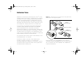
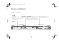
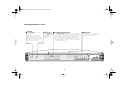
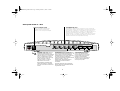
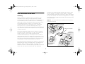
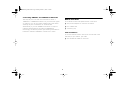
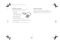
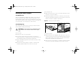
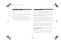
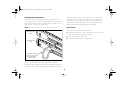
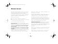
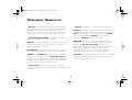
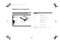
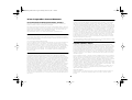
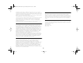
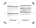
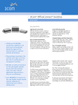
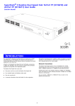
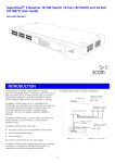
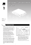
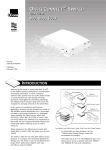
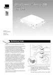
3C16734_Booklet.book Page i Monday, March 12, 2001 1:46 PM
OfficeConnect® Dual Speed Switch 5,
Switch 8
User Guide (3C16790, 3C16791)
3C16734_Booklet.book Page ii Monday, March 12, 2001 1:46 PM
3Com Corporation
■
5400 Bayfront Plaza
Copyright © 2001, 3Com Technologies. All rights reserved.
No part of this documentation may be reproduced in any form or by any means
or used to make any derivative work (such as translation, transformation, or
adaptation) without written permission from 3Com Technologies.
3Com Technologies reserves the right to revise this documentation and to make
changes in content from time to time without obligation on the part of 3Com
Technologies to provide notification of such revision or change.
3Com Technologies provides this documentation without warranty, term, or
condition of any kind, either implied or expressed, including, but not limited to,
the implied warranties, terms or conditions of merchantability, satisfactory
quality, and fitness for a particular purpose. 3Com may make improvements or
changes in the product(s) and/or the program(s) described in this documentation
at any time.
If there is any software on removable media described in this documentation, it
is furnished under a license agreement included with the product as a separate
document, in the hard copy documentation, or on the removable media in a
directory file named LICENSE.TXT or !LICENSE.TXT. If you are unable to locate a
copy, please contact 3Com and a copy will be provided to you.
UNITED STATES GOVERNMENT LEGEND
If you are a United States government agency, then this documentation and the
software described herein are provided to you subject to the following:
All technical data and computer software are commercial in nature and
developed solely at private expense. Software is delivered as “Commercial
Computer Software” as defined in DFARS 252.227-7014 (June 1995) or as a
“commercial item” as defined in FAR 2.101(a) and as such is provided with only
such rights as are provided in 3Com’s standard commercial license for the
Software. Technical data is provided with limited rights only as provided in DFAR
252.227-7015 (Nov 1995) or FAR 52.227-14 (June 1987), whichever is
applicable. You agree not to remove or deface any portion of any legend
provided on any licensed program or documentation contained in, or delivered to
you in conjunction with, this User Guide.
Unless otherwise indicated, 3Com registered trademarks are registered in the
United States and may or may not be registered in other countries.
3Com and OfficeConnect are registered trademarks of 3Com Corporation. The
3Com logo is a trademark of 3Com Corporation
■
Santa Clara, California
■
95052-8145
Microsoft, MS-DOS, Windows, and Windows NT are registered trademarks of
Microsoft Corporation. Novell and NetWare are registered trademarks of
Novell, Inc.
All other company and product names may be trademarks of the respective
companies with which they are associated.
The OfficeConnect Dual Speed Switches are covered by a lifetime limited
warranty, which also includes the power adapter. To qualify for the warranty, you
must submit a registration card or register on-line at
http://support.3com.com/registration/frontpg.pl. The OfficeConnect Dual
Speed Switches are covered by a free 90-day telephone support.
The lifetime limited warranty is not offered where restricted or prohibited by law.
Please e-mail any comments about this document to 3Com at:
pddtechpubs_ [email protected]. Please include the document title
(OfficeConnect Dual Speed Switch 5, Switch 8 User Guide), part number
(DUA1679-0AAA01) and if appropriate, the page number.
3C16734_Booklet.book Page 3 Monday, March 12, 2001 1:46 PM
Introduction 4
Dimensions and Standards 19
Dimensions and Operating Conditions 19
Standards 19
Creating your Network 4
Dual Speed Switch 4—Front 5
Dual Speed Switch 8 and Dual Speed 16—Front 6
All Units—Rear 7
How the Switch Can Be Used 8
Switching 8
Connecting 10BASE-T and 100BASE-TX Networks 9
Before You Start 9
Unit Connections 9
Workstation Connections 10
Twisted Pair (TP) Cables 10
Stacking the Units Together 11
The Rubber Feet 11
The Stacking Clip 11
Positioning Your Switch 12
Securing Your Switch 12
Connecting Workstations and Other Equipment to Your
Switch 13
Connecting OfficeConnect Units to Your Switch 13
Checking Unit Connections 14
Spot Checks 14
Environmental Statements 20
End Of Life Statement 20
Regulated Materials Statement 20
Environmental Statement about the Documentation 20
Environmental Statement about the Product Packaging 20
Important Safety Information 21
Wichtige Sicherheitshinweise 22
Consignes importantes de sécurité 23
Technical Support 24
Online Technical Services 24
World Wide Web Site 24
3Com Knowledgebase Web Services 24
Support from Your Network Supplier 25
Support from 3Com 25
Returning Products for Repair 27
3Com Corporation Limited Warranty 28
Regulatory Notices 30
Problem Solving 15
Networking Terminology 17
3
3C16734_Booklet.book Page 4 Monday, March 12, 2001 1:46 PM
4
3C16734_Booklet.book Page 4 Monday, March 12, 2001 1:46 PM
INTRODUCTION
Welcome to the world of networking with 3Com® . In the
modern business environment, communication and sharing
information is crucial. Computer networks have proved to
be one of the fastest modes of communication but until
recently, only large businesses could afford the networking
advantage. The OfficeConnect® product range from 3Com
has changed this, bringing networks to the small office.
Figure 1 Small Network with OfficeConnect Dual Speed Switch
(Circle Shows Units Clipped Together)
10BASE-T
OfficeConnect hub
As the power of workstations and business applications
increases, heavier demands are made on the available
network bandwidth that if unchecked, can lead to
performance problems in a hub-based setup. Installing the
OfficeConnect Dual Speed Switch 5 (3C16790) or Switch 8
(3C16791) allows your network to be segmented so that
traffic can be contained effectively, reducing the overall load
without affecting access to critical resources.
OfficeConnect Switch
100BASE-TX
OfficeConnect hub
This guide will use the term 'Switch' when referring to the
Dual Speed Switch 5 or Switch 8.
The Switch is ideal for use with other OfficeConnect
products, as shown in Figure 1. It is compact and
attractively designed for desktop use. The Switch is part of
the OfficeConnect range which neatly stack together with
the OfficeConnect Stacking Clip.
The 3C16790 has five 10/100BASE-TX ports while the
3C16791 has eight 10/100BASE-TX ports. This allows you to
set up a network with both 10BASE-T and 100BASE-TX
hubs and workstations.
4
3C16734_Booklet.book Page 5 Monday, March 12, 2001 1:46 PM
CREATING YOUR NETWORK
Dual Speed Switch 5—Front
Alert LED
If the Alert LED is off, the unit is
operating correctly.
After power on, the Alert LED
remains lit (orange) for a short
period of time while performing a
self test. If it is continuously lit there
may be a problem. Refer to the
“Problem Solving” section.
Power LED
Port Status and Activity LEDs
Duplex LED’s
If the Power LED
is lit (green), the
power supply to
the Switch is
present.
If the Port Status LED is off there is nothing connected to
the port, or the connected device is turned off or there may
be a problem with the connectivity (refer to the “Problem
Solving” section). If the LED is green the speed of the link to
the connected device is at 100 Mbps (100BASE-Tx). If the
LED is yellow the speed of the link to the connected device is
at 10 Mbps (10BASE-T). The LED will flash to indicate traffic
is passing through that port.
If the Duplex LED is lit (yellow), the port
is in full duplex mode. If the LED is off,
the port is in half duplex mode.
5
3C16734_Booklet.book Page 6 Monday, March 12, 2001 1:46 PM
Dual Speed Switch 8 —Front
Alert LED
If the Alert LED is off, the unit is
operating correctly.
After power on, the Alert LED
remains lit (orange) for a short
period of time while performing a
self test. If it is continuously lit there
may be a problem. Refer to the
“Problem Solving” section.
Power LED
Port Status and Activity LEDs
Duplex LED’s
If the Power LED
is lit (green), the
power supply to
the Switch is
present.
If the Port Status LED is off there is nothing connected to
the port, or the connected device is turned off or there may
be a problem with the connectivity (refer to the “Problem
Solving” section). If the LED is green the speed of the link to
the connected device is at 100 Mbps (100BASE-Tx). If the
LED is yellow the speed of the link to the connected device is
at 10 Mbps (10BASE-T). The LED will flash to indicate traffic
is passing through that port.
If the Duplex LED is lit (yellow), the port
is in full duplex mode. If the LED is off,
the port is in half duplex mode.
6
3C16734_Booklet.book Page 7 Monday, March 12, 2001 1:46 PM
Dual Speed Switch 8 —Rear
Power Adapter socket
10/100BASE-TX ports
Only use the power adapter that is
supplied with this OfficeConnect
Switch. Do not use any other adapter.
Use suitable TP cable with RJ-45 connectors. You can connect the
OfficeConnect Switch to any workstation or OfficeConnect hub that
has a 10BASE-T, 100BASE-TX or 10/100BASE-TX port. Each port is
capable of auto-negotiating for 10 Mbps or 100 Mbps operation. All
ports have an automatic MDI / MDIX feature, it means either a
'straight through' or 'crossover' UTP cable can be used to connect to
any port. The switch will automatically detect which wiring practice
has been followed and will compensate accordingly.
WARNING: RJ-45 ports. These are
shielded RJ-45 data sockets. They
cannot be used as standard traditional
telephone sockets, or to connect the
unit to a traditional PBX or public
telephone network. Only connect RJ45 data connectors, network
telephony systems, or network
telephones to these sockets.
Either shielded or unshielded data
cables with shielded or unshielded
jacks can be connected to these data
sockets.
WARNHINWEIS: RJ-45-Anschlüsse Diese
Porte sind geschützte Datensteckdosen. Sie
dürfen weder wie normale traditionelle
Telefonsteckdosen noch für die Verbindung
der Einheit mit einem traditionellem
privatem oder öffentlichem Telefonnetzwerk
gebraucht werden. Nur RJ-45Datenanscluße, Telefonnetzsysteme or
Netztelefone an diese Steckdosen
anschließen.
Entweder geschützte oder ungeschützte
Buchsen dürfen an diese Datensteckdosen
angeschlossen werden.
7
AVERTISSEMENT: Ports RJ-45.
Ceux-ci sont protégés par des
prises de données. Ils ne peuvent
pas être utilisés comme prises de
téléphone conventionnelles
standard, ni pour la connection de
l’unité à un réseau téléphonique
central privé ou public.
3C16734_Booklet.book Page 8 Monday, March 12, 2001 1:46 PM
whether it should be directed through the normal or high
priority channel. This feature can be useful for example
during excessive loads when one type of traffic may require
priority over another. The Switch is configured to to comply
with VLAN priority tagged frames and IP TOS / DSCP priority
encoded frames.
How the Switch Can Be Used
Switching
When a network of repeater hubs is in operation, any
information that is sent by the workstations is passed
around the whole network (regardless of the destination of
the information). This can result in a lot of unnecessary
traffic that can slow the network down. The Switch solves
this problem because it ‘listens’ to the network and
automatically learns what workstations can be reached
through its ports. It can then selectively pass on any
information by transmitting the traffic from the relevant port
only (instead of all ports like a repeater hub). This operation
is called ‘switching’.
Figure 2 The Switch Separates Your Network and Controls the
Information Effectively
10BASE-T
OfficeConnect hub
OfficeConnect Switch
The Switch effectively divides up your network, localizing
the network traffic and passing on traffic as necessary (as
shown in Figure 2). If you have workstations that
communicate frequently in the same part of the network,
traffic between them is not passed on unnecessarily to the
remainder of the network, thereby reducing the load. If you
have any high performance workstations that require a lot
of bandwidth, connect them directly to the Switch.
100BASE-TX
OfficeConnect
hub
The Switches have an additional new feature to aid network
performance at times of excessive load. It is called Priority
Queuing. When a packet is received, the Switch will
examine it to see if it has been priority encoded. If it has the
Switch will then read the priority level and determine
100BASE-TX
High performance
workstation
8
3C16734_Booklet.book Page 9 Monday, March 12, 2001 1:46 PM
Connecting 10BASE-T and 100BASE-TX Networks
Before You Start
The 10/100 ports can each be connected to either a
10BASE-T or 100BASE-TX network. If you have both types
of network, you can join them together using the Switch
allowing all your workstations to communicate.
Alternatively, if you use 10BASE-T and want to improve
network performance by introducing 100BASE-TX
technology, the Switch protects your existing workstations
because it maintains 10BASE-T connections to them.
Your OfficeConnect Dual Speed Switch comes with:
■
One power adapter for use with the Switch.
■
Four rubber feet.
■
A stacking clip.
Unit Connections
To connect OfficeConnect units (such as hubs and other
switches) to your Switch, you need:
■
9
One suitable TP cable for each unit.
3C16734_Booklet.book Page 10 Monday, March 12, 2001 1:46 PM
Workstation Connections
Twisted Pair (TP) Cables
To connect workstations or other equipment (such as
servers) directly to your Switch, you need:
Cables can be shielded (screened) or unshielded; we
recommend that you use shielded cable. Cables used for
100BASE-TX connections must be data grade (Category 5).
The maximum length you can use is 100m (328ft).
1 One 10BASE-T,
100BASE-TX or
10/100BASE-TX adapter
card for each workstation.
3Com produce a range of
easy to install network
adapters, which provide
your workstation with a
10BASE-T or 100BASE-TX connection.
3
2
1
2 An operating system (for example, NetWare or Windows
95/98) with network support configured, running on
your workstations.
3 One suitable twisted pair cable for each workstation.
10
3C16734_Booklet.book Page 11 Monday, March 12, 2001 1:46 PM
To fit another unit:
Stacking the Units Together
1 Rest the second unit on top of the clip and align it with
the front of the unit below.
The Rubber Feet
2 Press down gently on the unit to secure it onto the clip,
The four self-adhesive rubber feet prevent your hub from
moving around on your desk. Only stick the feet to the
marked areas at each corner of the underside of your hub if
you intend to place the unit directly on top of the desk. Do
not fix the feet if you are going to use the clip.
ensuring the fastening pieces fit into the slots on the unit
below, as shown in Figure 3 (picture 2).
Figure 3
Stacking Your Units Together
1
Fastening
Piece
The Stacking Clip
2
Fastening
Piece
The stacking clip allows you to stack your OfficeConnect
units together neatly and securely.
CAUTION: You can stack up to a maximum of four
units. Smaller units must be stacked above larger
units.
To fit the clip:
To remove the clip:
1 Place your unit on a flat surface.
1 Remove the top unit together with the clip. If you hook
2 Fit the clip across the top of the unit, as shown in
a finger around one of the the fastening pieces and then
pull it gently from out of the slot, the clip should come
away with the upper unit attached to it.
Figure 3 (picture 1), ensuring that the longer sections of
the fastening pieces are pointing downwards.
3 Align the fastening pieces over the slots found on each
2 Push the clip in the center, so it bends towards the base
side of the unit.
of the unit, and then separate once the clip is loose.
4 Push the clip down gently to secure it, ensuring the
fastening pieces snap into the slots on the unit.
11
3C16734_Booklet.book Page 12 Monday, March 12, 2001 1:46 PM
Positioning Your Switch
Securing Your Switch
When installing your Switch, ensure:
There are two slots on the underside of the OfficeConnect
Switch that can be used for wall mounting. It is
recommended that you mount the Switch with the LEDs
facing upwards to prevent dust entering the cooling vents.
■
It is out of direct sunlight and away from sources of
heat.
■
Cabling is away from power lines, fluorescent lighting
fixtures, and sources of electrical noise such as radios,
transmitters and broadband amplifiers.
■
Water or moisture cannot enter the case of the unit.
■
Air flow around the unit and through the vents in the
side of the case is not restricted. We recommend you
provide a minimum of 25mm (1in.) clearance.
When wall mounting the unit, ensure that it is within
reach of the power outlet.
You need two suitable screws. Ensure that the wall you are
going to use is smooth, flat, dry and sturdy. Make two
screw holes which are 150mm (5.9in.) apart. Use the guide
on page 31 to mark the position of the holes. Fix the screws
into the wall, leaving their heads 3mm (0.12in.) clear of the
wall surface.
Remove any connections to the unit and locate it over the
screw heads. When in line, gently push the unit on to the
wall and move it downwards to secure. When making
connections, be careful not to push the unit up and off the
wall.
CAUTION: Only wall mount single units, do not wall
mount stacked units.
Also available from 3Com, is the OfficeConnect Mounting
Unit (part number 3C16765). This allows you to firmly
secure a stack of OfficeConnect devices to the desktop or
onto a shelf in a rack.
12
3C16734_Booklet.book Page 13 Monday, March 12, 2001 1:46 PM
This may take a few seconds and the outcome will be
reflected in the LED’s on the front of the Switch’.
Connecting Workstations and Other
Equipment to Your Switch
If the equipment connected to the Switch does not
support auto-negotiation or if it has been disabled, it
must be configured to operate in half duplex mode.
WARNING: Please read the ‘Important Safety
Information’ section before you start.
WARNHINWEIS: Bitte lesen Sie den Abschnitt
‘Wichtige Sicherheitsinformationen’ sorgfältig durch,
bevor Sie das Gerät einschalten.
The Switch detects all port connections, so you can start
using your network immediately. If you need more ports,
simply add another OfficeConnect unit.
AVERTISSEMENT: Veuillez lire attentivement la
section “Consignes importantes de sécurité” avant de
mettre en route.
Connecting OfficeConnect Units to Your Switch
You can increase the number of workstations that can
connect to your network by adding OfficeConnect units
(such as hubs and other switches). You can connect either a
10BASE-T or a 100BASE-TX OfficeConnect unit to each port
of the Switch.
CAUTION: Do not power the Switch off and on quickly.
Wait about five seconds between power cycles.
10BASE-T cables are very easy to use. To connect a
10BASE-T cable, simply slot the connector into the relevant
RJ-45 port. When the connector is fully in, its latch locks it
into place. To disconnect the cable, push the connector’s
latch in and remove it.
When a TP cable is connected to the Switch at one end and
a workstation other equipment at other and both unit are
powered, the Switch will automtically detect whether a
’straight ’ or ’Crossover’ cable is being used and will
compensate if required. The units will then ’Auto negotiate’
to determine the fastest possible link speed between them.
13
3C16734_Booklet.book Page 14 Monday, March 12, 2001 1:46 PM
feature, it means either a 'straight through' or 'crossover'
UTP cable can be used in any Switch port to make the
connection to other switches, hubs and workstations. The
switch will automatically detect which wiring practice has
been followed and will compensate accordingly.
Checking Unit Connections
When you have connected all your units, power on the
units and the Switch. The Port Status LEDs for the ports you
have used on both the units and the Switch should be on. If
they are not, check your connections.
Figure 4
Spot Checks
Correct Connections for an OfficeConnect Hub
At frequent intervals, visually check that:
OfficeConnect
Switch
OfficeConnect
Hub
Twisted pair cable
with RJ-45 connectors.
Maximum length is
100m (328ft)
There is no uplink/normal push switch that is usually
associated with OfficeConnect products. Instead the product
has an automatic MDI / MDIX (Media Dependant Interface)
14
■
The Alert LED is off — this is the best way to find out if
there are problems with your network.
■
Case vents are not obstructed.
■
Cabling is secure and not pulled taut.
3C16734_Booklet.book Page 15 Monday, March 12, 2001 1:46 PM
PROBLEM SOLVING
The Switch has been designed to aid you when detecting
and solving possible problems with your network. These
problems are rarely serious; the cause is usually a
disconnected or damaged cable, or incorrect configuration.
If this section does not solve your problem, contact your
supplier for information on what to do next.
Please refer to pages 5 and 6 'Creating your Network' for a
full description of the LED's.
Perform these actions first:
You may find a TP cable works when connected to the
Switch but doesn't if it is disconnected from the Switch and
connected to a different piece of equipment. This may be
due to the advanced automatic MDI / MDIX feature of the
Switch that the other equipment may not have.
■
Ensure all network equipment is powered on.
■
Power each piece of network equipment off, wait about
5 seconds and then power each one on.
lf the Port Status LED has not lit after several seconds
ensure the connected device is powered, the TP cable is not
damaged and that it is correctly inserted at both ends.
Check the following symptoms and solutions:
Alert LED continuously lit. If the Alert LED is lit, there is a
problem with the network. Remove the port connections
one at a time, waiting a few seconds between each port. If
the Alert LED goes off, there is either a network loop or an
excessive amount of broadcast traffic on that port
connection:
Power LED not lit. Check your power adapter connection.
If there is still no power, you may have a faulty power
adapter which needs replacing with another OfficeConnect
power adapter. Do not use any other power adapter
with the Switch.
Network loop — Examine your connections and remove the
loop. Each piece of equipment needs only one connection
to your Switch.
Port Status LED not lit for a port that has a TP cable
connected. After connection it may take several seconds
for the port status LED's to illuminate. The port status LED
should turn Green or Yellow for each port that is
connected. The Duplex LED may or may not illuminate.
Excessive amounts of broadcast frames — Some pieces of
network equipment operate by sending out broadcast
15
3C16734_Booklet.book Page 16 Monday, March 12, 2001 1:46 PM
frames regularly. Refer to the documentation that
accompanies the piece of network equipment.
If the Alert LED is still lit after removing all of your
connections, there may be a problem with your Switch.
Power it off, wait about 5 seconds and then power it on. If
the Alert LED comes back on continuously, contact your
supplier.
16
3C16734_Booklet.book Page 17 Monday, March 12, 2001 1:46 PM
NETWORKING TERMINOLOGY
A Network is a collection of workstations (for example,
IBM-compatible PCs) and other equipment (for example,
printers), connected for the purpose of exchanging
information or sharing resources. Networks vary in size,
some are within a single room, others span continents.
A segment is the length of cable connected to a port.
Packets are the units of information your workstations and
other equipment send to each other over the network. A
frame is the data part of the packet and can be unicast
(sent to a single device), multicast (sent to multiple
devices), or broadcast (sent to all devices).
A Local Area Network (LAN) is a network, usually in an
office, that spans no more than a single site.
Bandwidth refers to the amount of network traffic the
network can hold at any one time (information capacity)
measured in bits per second (bps). Workstations or
applications that use the network heavily are referred to as
using high bandwidth. Fast Ethernet has a higher
bandwidth than Ethernet, so it can cope with larger
amounts of traffic, which results in faster operation.
Ethernet is a type of LAN, referring to the technology used
to pass information around the network. It operates at
10Mbps (megabits per second).
Fast Ethernet is a type of LAN that runs up to 10 times
faster than standard Ethernet. It operates at 100Mbps.
10BASE-T and 100BASE-TX are the names given to the
Ethernet protocol that runs over Twisted Pair (TP) cable.
10BASE-T runs at 10Mbps whilst 100BASE-TX operates at
100Mbps. The OfficeConnect Hubs and Switches Use RJ-45
type connectors to connect your TP network.
Full duplex operation allows information to be transmitted
and received simultaneously and, in effect, doubles the
potential throughput of a link.
A network loop occurs when two pieces of network
equipment are connected to each other by two seperate
connections.
17
3C16734_Booklet.book Page 18 Monday, March 12, 2001 1:46 PM
Priority Queuing is the ability of a network to give and
maintain certain throughput levels for different applications
depending on the priority assigned to that application. At
excessive loads a packet with a higher priority will take a
greater precedence over a lower prioritised packet.
Automatic MDI / MDIX this feature automatically detects
which wiring practice that has been followed with regard to
the TP cable, ie if the TP cable is a 'straight through' wired
cable or a 'crossover' wired cable. The automatic MDI /
MDIX feature within the Switch will detect and compensate
accordingly.
18
3C16734_Booklet.book Page 19 Monday, March 12, 2001 1:46 PM
DIMENSIONS AND STANDARDS
Dimensions and Operating Conditions
Standards
Power requirement
Switch 5:
3.5 VA, 12 BThU/hr
Switch 8:
5.6 VA, 19.12 BThU/hr
Functional:
ISO 8802/3
IEEE 802.3, 802.3u
Safety:
UL 1950, EN 60950
CSA 22.2 #950, IEC60950
EMC:
EN 55022 Class B
EN 55024
FCC Part 15 Class B*
ICES-003 Class B
VCCI Class B
225 mm (8.08 in.)
0 to 40 °C (32 to 105 °F)
operating
Switch 5: 0.6 Kg (1.3 lb)
temperature
Switch 8: 0.6 Kg (1.3 lb)
35.35 mm
(1.36 in.)
135.4 mm (5.33 in.)
0 to 90%
(non-condensing)
humidity
CNS 13438 Class A
Environmental:
EN 60068 (IEC 68)
*Refer to “Regulatory Notices” on page 30 for conditions of
operation.
19
3C16734_Booklet.book Page 20 Monday, March 12, 2001 1:46 PM
ENVIRONMENTAL STATEMENTS
It is the policy of 3Com Corporation to be
environmentally-friendly in all operations. To uphold our
policy, we are committed to:
End Of Life Statement
3Com processes allow for the recovery, reclamation and safe
disposal of all end-of-life electronic components.
■
Establishing environmental performance standards that
comply with national legislation and regulations.
Regulated Materials Statement
■
Conserving energy, materials and natural resources in all
operations.
3Com products do not contain any hazardous or
ozone-depleting material.
■
Reducing the waste generated by all operations.
■
Ensuring that all waste conforms to recognized
environmental standards.
Environmental Statement about the Documentation
The documentation for this product is printed on paper that
comes from sustainable, managed forests; it is fully
biodegradable and recyclable, and is completely
chlorine-free. The varnish is environmentally-friendly, and the
inks are vegetable-based with a low heavy-metal content.
■
Maximizing the recyclable and reusable content of all
products.
■
Ensuring that all products can be recycled, reused and
disposed of safely.
■
Ensuring that all products are labelled according to
recognized environmental standards.
Environmental Statement about the Product
Packaging
■
Improving our environmental record on a continual basis.
The packaging for this product is fully recyclable. It has a
recycled (post consumer) waste content of at least 40% by
weight, and no heavy-metal content.
20
3C16734_Booklet.book Page 21 Monday, March 12, 2001 1:46 PM
IMPORTANT SAFETY INFORMATION
WARNING: Warnings contain directions that you
must follow for your personal safety. Follow all
directions carefully.
You must read the following safety information
carefully before you install or remove the unit:
■
Exceptional care must be taken during installation and
removal of the unit.
■
Only stack the Switch with other OfficeConnect units.
■
To ensure compliance with international safety standards,
only use the power adapter that is supplied with the
unit.
■
The socket outlet must be near to the unit and easily
accessible. You can only remove power from the unit by
disconnecting the power cord from the outlet.
■
This unit operates under SELV (Safety Extra Low Voltage)
conditions according to IEC 950. The conditions are only
maintained if the equipment to which it is connected
also operates under SELV conditions.
■
There are no user-replaceable fuses or user-serviceable
parts inside the Switch. If you have a physical problem
with the unit that cannot be solved with problem solving
actions in this guide, contact your supplier.
■
Disconnect the power adapter before moving the unit.
WARNING: RJ-45 ports. These are shielded RJ-45
data sockets. They cannot be used as telephone
sockets. Only connect RJ-45 data connectors to these
sockets.
21
3C16734_Booklet.book Page 22 Monday, March 12, 2001 1:46 PM
WICHTIGE SICHERHEITSHINWEISE
WARNHINWEIS: Warnhinweise enthalten
Anweisungen, die Sie zu Ihrer eigenen Sicherheit
befolgen müssen. Alle Anweisungen sind sorgfältig zu
befolgen.
Sie müssen die folgenden Sicherheitsinformationen
sorgfältig durchlesen, bevor Sie das Geräts installieren
oder ausbauen:
■
Bei der Installation und beim Ausbau des Geräts ist mit
höchster Vorsicht vorzugehen.
■
Stapeln Sie das Geräts nur mit anderen OfficeConnect
Gerätes zusammen.
■
Aufgrund von internationalen Sicherheitsnormen darf das
Gerät nur mit dem mitgelieferten Netzadapter verwendet
werden.
■
Die Netzsteckdose muß in der Nähe des Geräts und
leicht zugänglich sein. Die Stromversorgung des Geräts
kann nur durch Herausziehen des Gerätenetzkabels aus
der Netzsteckdose unterbrochen werden.
■
Der Betrieb dieses Geräts erfolgt unter den
SELV-Bedingungen (Sicherheitskleinstspannung) gemäß
IEC 950. Diese Bedingungen sind nur gegeben, wenn
auch die an das Gerät angeschlossenen Geräte unter
SELV-Bedingungen betrieben werden.
■
Es sind keine von dem Benutzer zu ersetzende oder zu
wartende Teile in dem Gerät vorhanden. Wenn Sie ein
Problem mit dem Switch haben, das nicht mittels der
Fehleranalyse in dieser Anleitung behoben werden kann,
setzen Sie sich mit Ihrem Lieferanten in Verbindung.
■
Vor dem Ausbau des Geräts das Netzadapterkabel
herausziehen.
WARNHINWEIS: RJ-45-Anschlüsse. Dies sind
abgeschirmte RJ-45-Datenbuchsen. Sie können nicht
als Telefonanschlußbuchsen verwendet werden. An
diesen Buchsen dürfen nur RJ-45-Datenstecker
angeschlossen werden.
22
3C16734_Booklet.book Page 23 Monday, March 12, 2001 1:46 PM
CONSIGNES IMPORTANTES DE SÉCURITÉ
AVERTISSEMENT: Les avertissements présentent des
consignes que vous devez respecter pour garantir
votre sécurité personnelle. Vous devez respecter
attentivement toutes les consignes.
Nous vous demandons de lire attentivement les
consignes suivantes de sécurité avant d’installer ou de
retirer l’appareil:
■
Faites très attention lors de l'installation et de la dépose
du groupe.
■
Seulement entasser le moyer avec les autres moyeux
OfficeConnects.
■
Pour garantir le respect des normes internationales de
sécurité, utilisez uniquement l'adaptateur électrique remis
avec cet appareil.
■
La prise secteur doit se trouver à proximité de l’appareil
et son accès doit être facile. Vous ne pouvez mettre
l’appareil hors circuit qu'en débranchant son cordon
électrique au niveau de cette prise.
■
L’appareil fonctionne à une tension extrêmement basse
de sécurité qui est conforme à la norme CEI 950. Ces
conditions ne sont maintenues que si l'équipement
auquel il est raccordé fonctionne dans les mêmes
conditions.
■
Il n’y a pas de parties remplaceables par les utilisateurs
ou entretenues par les utilisateurs à l’intérieur du moyeu.
Si vous avez un problème physique avec le moyeu qui ne
peut pas être résolu avec les actions de la résolution des
problèmes dans ce guide, contacter votre fournisseur.
■
Débranchez l'adaptateur électrique avant de retirer cet
appareil.
AVERTISSEMENT: Ports RJ-45. Il s'agit de prises
femelles blindées de données RJ-45. Vous ne pouvez
pas les utiliser comme prise de téléphone. Branchez
uniquement des connecteurs de données RJ-45 sur
ces prises femelles.
23
3C16734_Booklet.book Page 24 Monday, March 12, 2001 1:46 PM
TECHNICAL SUPPORT
3Com provides easy access to technical support information
through a variety of services. This section describes these
services.
support options that range from technical education to
maintenance and professional services.
Information contained in this section is correct at time of
publication. For the most recent information, 3Com
recommends that you access the 3Com Corporation World
Wide Web site.
3Com Knowledgebase Web Services
This interactive tool contains technical product information
compiled by 3Com expert technical engineers around the
globe. Located on the World Wide Web at:
http://knowledgebase.3com.com.
Online Technical Services
This service gives all 3Com customers and partners
complementary, round-the-clock access to technical
information on most 3Com products.
3Com offers worldwide product support 24 hours a day,
7 days a week, through the following online systems:
■
World Wide Web site.
■
3Com Knowledgebase Web Services.
World Wide Web Site
To access the latest networking information on the
3Com Corporation World Wide Web site, enter this URL
into your Internet browser:
http://www.3com.com/
This service provides access to online support information
such as technical documentation and software, as well as
24
3C16734_Booklet.book Page 25 Monday, March 12, 2001 1:46 PM
Support from Your Network Supplier
Support from 3Com
If you require additional assistance, contact your network
supplier. Many suppliers are authorized 3Com service
partners who are qualified to provide a variety of services,
including network planning, installation, hardware
maintenance, application training, and support services.
If you are unable to obtain assistance from the 3Com online
technical resources or from your network supplier, 3Com
offers technical telephone support services. To find out more
about your support options, call the 3Com technical
telephone support phone number at the location nearest
you.
When you contact your network supplier for assistance,
have the following information ready:
■
Product model name, part number, and serial number.
■
A list of system hardware and software, including revision
levels.
■
Diagnostic error messages.
■
Details about recent configuration changes, if applicable.
When you contact 3Com for assistance, have the following
information ready:
If you are unable to contact your network supplier, see the
following section on how to contact 3Com.
25
■
Product model name, part number, and serial number.
■
A list of system hardware and software, including revision
levels.
■
Diagnostic error messages.
■
Details about recent configuration changes, if applicable.
3C16734_Booklet.book Page 26 Monday, March 12, 2001 1:46 PM
Here is a list of worldwide technical telephone support numbers. These numbers are correct at the time of publication.
Refer to the 3Com Web site for updated information.
Country
Asia, Pacific Rim
Australia
Hong Kong
India
Telephone Number
Singapore
S. Korea
From anywhere in S. Korea:
From Seoul:
Taiwan, R.O.C.
Thailand
1 800 678 515
800 933 486
+61 2 9937 5085 or
000800 6501111
001 800 61 009
03 5783 1270
1800 801 777
0800 446 398
+61 2 9937 5083
1235 61 266 2602
10800 61 00137 or
021 6350 1590 or
00800 0638 3266
800 6161 463
82 2 3455 6455
00798 611 2230
00798 611 2230
0080 611 261
001 800 611 2000
Europe, Middle East and
Africa
From anywhere in these
regions, call:
+44 (0)1442 435529 phone
+44 (0)1442 436722 fax
Indonesia
Japan
Malaysia
New Zealand
Pakistan
Philippines
P.R. of China
Country
Telephone Number
Austria
Belgium
Denmark
Finland
France
Germany
Hungary
Ireland
Israel
Italy
Luxembourg
Netherlands
Norway
Poland
Portugal
South Africa
Spain
Sweden
Switzerland
U.K.
0800 297468
0800 71429
800 17309
0800 113153
0800 917959
0800 1821502
06800 12813
1800 553117
1800 9453794
800 8 79489
0800 3625
0800 0227788
800 11376
00800 3111206
0800 831416
0800 995014
900 983125
020 795482
0800 55 3072
0800 966197
Latin America
Brazil
Mexico
Puerto Rico
Central and South America
0800 13 3266
01 800 849CARE
800 666 5065
AT&T +800 998 2112
North America
Europe and South Africa
From the following countries,
you may use the
toll-free numbers:
1 800 NET 3Com
(1 800 638 3266)
Enterprise Customers:
1 800 876-3266
26
3C16734_Booklet.book Page 27 Monday, March 12, 2001 1:46 PM
Country
Returning Products for Repair
Austria
Belgium
Denmark
Finland
France
Germany
Hungary
Ireland
Israel
Italy
Netherlands
Norway
Poland
Portugal
South Africa
Spain
Sweden
Switzerland
U.K.
To obtain an authorization number, call or fax:
Telephone Number
Fax Number
Asia, Pacific Rim
+ 65 543 6500
+ 65 543 6348
Europe, South Africa,
and Middle East
+ 31 30 6029900
+ 31 30
6029999
Central and South
America
525 201 0075
Argentina
Bolivia
Brazil
Caribbean
Chile
Colombia
Ecuador
Mexico
Paraguay
Peru
Uruguay
Venezuela
Fax Number
From the following countries, you may call the toll-free numbers;
select option 2 and then option 2:
Before you send a product directly to 3Com for repair, you
must first obtain a Return Material Authorization (RMA)
number. Products sent to 3Com without authorization
numbers will be returned to the sender unopened, at the
sender’s expense.
Country
Telephone Number
0810 222 3266
511 241 1691
0800 133266 or
55 11 5643 2700
525 201 0004
562 240 6200
525 201 0004
525 201 0004
525 201 0004
525 201 0004
511 241 1691
525 201 0004
525 201 0004
U.S.A. and Canada
0800 297468
0800 71429
800 17309
0800 113153
0800 917959
0800 1821502
00800 12813
1800 553117
1800 9453794
1678 79489
0800 0227788
800 11376
00800 3111206
0800 831416
0800 995014
900 983125
020 795482
0800 55 3072
0800 966197
1 800 NET 3Com
(1 800 638 3266)
Enterprise Customers:
1 800 876 3266
27
1 408 326 7120
(not toll-free)
3C16734_Booklet.book Page 28 Monday, March 12, 2001 1:46 PM
3Com Corporation LIMITED WARRANTY
YEAR 2000 WARRANTY
3Com OfficeConnect Dual Speed Switch 5, Switch 8
In addition to the Hardware Warranty and Software Warranty stated above, 3Com warrants
that each product sold or licensed to Customer on and after January 1, 1998 that is date
sensitive will continue performing properly with regard to such date data on and after January
1, 2000, provided that all other products used by Customer in connection or combination with
the 3Com product, including hardware, software, and firmware, accurately exchange date data
with the 3Com product, with the exception of those products identified at 3Com’s Web site,
http://www.3com.com/products/yr2000.html, as not meeting this standard. If it appears that
any product that is stated to meet this standard does not perform properly with regard to such
date data on and after January 1, 2000, and Customer notifies 3Com before the later of April
1, 2000, or ninety (90) days after purchase of the product from 3Com or its authorized reseller,
3Com shall, at its option and expense, provide a software update which would effect the
proper performance of such product, repair such product, deliver to Customer an equivalent
product to replace such product, or if none of the foregoing is feasible, refund to Customer
the purchase price paid for such product.
The duration of the warranty for the OfficeConnect Dual Speed Switch 5 (3C16790) and
Switch 8 (3C16791) is lifetime, including the power adapter.
The OfficeConnect Dual Speed Switches are covered by a lifetime limited warranty, which also
includes the power adapter. To qualify for the warranty, you must submit a registration card or
register on-line at http://support.3com.com/registration/frontpg.pl. The OfficeConnect Dual
Speed Switches are covered by a free 90-day telephone support.
The lifetime limited warranty is not offered where restricted or prohibited by law.
HARDWARE
3Com warrants this hardware product to be free from defects in workmanship and materials,
under normal use and service, for the following length of time from the date of purchase from
3Com or its authorized reseller:
Any software update or replaced or repaired product will carry a Year 2000 Warranty for ninety
(90) days after purchase or until April 1, 2000, whichever is later.
One (1) year (unless otherwise specified above)
3Com’s sole obligation under this express warranty shall be, at 3Com’s option and expense, to
repair the defective product or part, deliver to Customer an equivalent product or part to
replace the defective item, or if neither of the two foregoing options is reasonably available,
3Com may, in its sole discretion, refund to Customer the purchase price paid for the defective
product. All products that are replaced will become the property of 3Com. Replacement
products may be new or reconditioned. 3Com warrants any replaced or repaired product or
part for ninety (90) days from shipment, or the remainder of the initial warranty period,
whichever is longer.
OBTAINING WARRANTY SERVICE
Customer must contact a 3Com Corporate Service Center or an Authorized 3Com Service
Center within the applicable warranty period to obtain warranty service authorization. Dated
proof of purchase from 3Com or its authorized reseller may be required. Products returned to
3Com's Corporate Service Center must be pre-authorized by 3Com with a Return Material
Authorization (RMA) number marked on the outside of the package, and sent prepaid and
packaged appropriately for safe shipment, and it is recommended that they be insured or sent
by a method that provides for tracking of the package. The repaired or replaced item will be
shipped to Customer, at 3Com's expense, not later than thirty (30) days after 3Com receives
the defective product.
SOFTWARE
3Com warrants that each software program licensed from it will perform in substantial
conformance to its program specifications, for a period of ninety (90) days from the date of
purchase from 3Com or its authorized reseller. 3Com warrants the media containing software
against failure during the warranty period. No updates are provided. 3Com's sole obligation
under this express warranty shall be, at 3Com's option and expense, to refund the purchase
price paid by Customer for any defective software product, or to replace any defective media
with software which substantially conforms to applicable 3Com published specifications.
Customer assumes responsibility for the selection of the appropriate applications program and
associated reference materials. 3Com makes no warranty or representation that its software
products will meet Customer’s requirements or work in combination with any hardware or
applications software products provided by third parties, that the operation of the software
products will be uninterrupted or error free, or that all defects in the software products will be
corrected. For any third party products listed in the 3Com software product documentation or
specifications as being compatible, 3Com will make reasonable efforts to provide compatibility,
except where the non-compatibility is caused by a "bug" or defect in the third party's product
or from use of the software product not in accordance with 3Com’s published specifications or
user manual.
Dead- or Defective-on-Arrival. In the event a product completely fails to function or exhibits a
defect in materials or workmanship within the first forty-eight (48) hours of installation but no
later than thirty (30) days after the date of purchase, and this is verified by 3Com, it will be
considered dead- or defective-on-arrival (DOA) and a replacement shall be provided by advance
replacement. The replacement product will normally be shipped not later than three (3)
business days after 3Com’s verification of the DOA product, but may be delayed due to export
or import procedures. When an advance replacement is provided and Customer fails to return
the original product to 3Com within fifteen (15) days after shipment of the replacement, 3Com
will charge Customer for the replacement product, at list price.
3Com shall not be responsible for any software, firmware, information, or memory data of
Customer contained in, stored on, or integrated with any products returned to 3Com for
repair, whether under warranty or not.
ADDITIONAL SERVICES:
Telephone Support. This OfficeConnect product comes with telephone technical support for
ninety (90) days. The ninety (90) day period begins on the date of Customer's product
purchase.
28
3C16734_Booklet.book Page 29 Monday, March 12, 2001 1:46 PM
The telephone technical support is available from 3Com from 9 a.m. to 5 p.m., local time,
Monday through Friday, excluding local holidays. Telephone technical support is limited to the
3Com products designated above and may include assistance with installation, product specific
configuration, and identification of equipment problems. Please refer to the Technical Support
appendix in the User Guide for telephone numbers.
DISCLAIMER
Some countries, states, or provinces do not allow the exclusion or limitation of implied
warranties or the limitation of incidental or consequential damages for certain products
supplied to consumers, or the limitation of liability for personal injury, so the above limitations
and exclusions may be limited in their application to you. When the implied warranties are not
allowed to be excluded in their entirety, they will be limited to the duration of the applicable
written warranty. This warranty gives you specific legal rights which may vary depending on
local law.
Response to requests for telephone technical support will be in the form of a return call from a
3Com representative by close of business the following business day.
To qualify for this 90 days of telephone technical support, you must register on the 3Com Web
site at http://support.3Com.com/index.htm, and provide your date of purchase, product
number, and serial number. 3Com reserves the right to modify or cancel this telephone
support offering at any time, without advance notice. This offer is not available where
prohibited or restricted by law.
GOVERNING LAW
3Com’s Web and Bulletin Board Service are available at no charge, and provide software and
firmware upgrades, a bug list, and technical information about 3Com products.
This Limited Warranty shall be governed by the laws of the State of California, U.S.A. excluding
its conflicts of laws principles and excluding the United Nations Convention on Contracts for
the International Sale of Goods.
WARRANTIES EXCLUSIVE
3Com Corporation
5400 Bayfront Plaza
Santa Clara, CA 95054
(408) 326-5000
IF A 3COM PRODUCT DOES NOT OPERATE AS WARRANTED ABOVE, CUSTOMER'S SOLE
REMEDY FOR BREACH OF THAT WARRANTY SHALL BE REPAIR, REPLACEMENT, OR REFUND OF
THE PURCHASE PRICE PAID, AT 3COM'S OPTION. TO THE FULL EXTENT ALLOWED BY LAW,
THE FOREGOING WARRANTIES AND REMEDIES ARE EXCLUSIVE AND ARE IN LIEU OF ALL
OTHER WARRANTIES, TERMS, OR CONDITIONS, EXPRESS OR IMPLIED, EITHER IN FACT OR BY
OPERATION OF LAW, STATUTORY OR OTHERWISE, INCLUDING WARRANTIES, TERMS, OR
CONDITIONS OF MERCHANTABILITY, FITNESS FOR A PARTICULAR PURPOSE, SATISFACTORY
QUALITY, CORRESPONDENCE WITH DESCRIPTION, AND NON-INFRINGEMENT, ALL OF WHICH
ARE EXPRESSLY DISCLAIMED. 3COM NEITHER ASSUMES NOR AUTHORIZES ANY OTHER
PERSON TO ASSUME FOR IT ANY OTHER LIABILITY IN CONNECTION WITH THE SALE,
INSTALLATION, MAINTENANCE OR USE OF ITS PRODUCTS.
3COM SHALL NOT BE LIABLE UNDER THIS WARRANTY IF ITS TESTING AND EXAMINATION
DISCLOSE THAT THE ALLEGED DEFECT OR MALFUNCTION IN THE PRODUCT DOES NOT EXIST
OR WAS CAUSED BY CUSTOMER'S OR ANY THIRD PERSON'S MISUSE, NEGLECT, IMPROPER
INSTALLATION OR TESTING, UNAUTHORIZED ATTEMPTS TO OPEN, REPAIR OR MODIFY THE
PRODUCT, OR ANY OTHER CAUSE BEYOND THE RANGE OF THE INTENDED USE, OR BY
ACCIDENT, FIRE, LIGHTNING, OTHER HAZARDS, OR ACTS OF GOD.
LIMITATION OF LIABILITY
TO THE FULL EXTENT ALLOWED BY LAW, 3COM ALSO EXCLUDES FOR ITSELF AND ITS
SUPPLIERS ANY LIABILITY, WHETHER BASED IN CONTRACT OR TORT (INCLUDING
NEGLIGENCE), FOR INCIDENTAL, CONSEQUENTIAL, INDIRECT, SPECIAL, OR PUNITIVE
DAMAGES OF ANY KIND, OR FOR LOSS OF REVENUE OR PROFITS, LOSS OF BUSINESS, LOSS OF
INFORMATION OR DATA, OR OTHER FINANCIAL LOSS ARISING OUT OF OR IN CONNECTION
WITH THE SALE, INSTALLATION, MAINTENANCE, USE, PERFORMANCE, FAILURE, OR
INTERRUPTION OF ITS PRODUCTS, EVEN IF 3COM OR ITS AUTHORIZED RESELLER HAS BEEN
ADVISED OF THE POSSIBILITY OF SUCH DAMAGES, AND LIMITS ITS LIABILITY TO REPAIR,
REPLACEMENT, OR REFUND OF THE PURCHASE PRICE PAID, AT 3COM'S OPTION. THIS
DISCLAIMER OF LIABILITY FOR DAMAGES WILL NOT BE AFFECTED IF ANY REMEDY PROVIDED
HEREIN SHALL FAIL OF ITS ESSENTIAL PURPOSE.
29
3C16734_Booklet.book Page 30 Monday, March 12, 2001 1:46 PM
REGULATORY NOTICES
CSA STATEMENT
This Class B digital apparatus meets all requirements of the Canadian Interference-Causing
Equipment Regulations.
FCC STATEMENT
Cet appareil numérique de la classe B respecte toutes les exigences du Règlement sur le
matériel brouilleur du Canada.
This equipment has been tested and found to comply with the limits for a Class B digital
device, pursuant to Part 15 of the FCC Rules, and the Canadian Department of
Communications Equipment Standards entitled, “Digital Apparatus,” ICES-003. These limits are
designed to provide reasonable protection against harmful interference in a residential
installation. This equipment generates, uses and can radiate radio frequency energy and, if not
installed and used in accordance with the instructions, may cause harmful interference to radio
communications. However, there is no guarantee that interference will not occur in a particular
installation.
VCCI STATEMENT
If this equipment does cause interference to radio or television reception, which can be
determined by turning the equipment off and on, the user is encouraged to try to correct the
interference by one or more of the following measures:
■
Reorient the receiving antenna.
■
Relocate the equipment with respect to the receiver.
■
Move the equipment away from the receiver.
■
Plug the equipment into a different outlet so that equipment and receiver are on different
branch circuits.
■
Consult the dealer or an experienced radio/television technician for help.
BCIQ STATEMENT
INFORMATION TO THE USER
The user may find the following booklet prepared by the Federal Communications Commission
helpful:
How to Identify and Resolve Radio-TV Interference Problems
This booklet is available from the U.S. Government Printing Office, Washington, DC 20402,
Stock No. 004-000-00345-4.
In order to meet FCC emissions limits, this equipment must be used only with cables which
comply with IEEE 802.3.
Wall mounting screw hole guide
150mm (5.9in.)
30
3C16734_Booklet.book Page 31 Monday, March 12, 2001 1:46 PM
Part No. DUA1679-0AAA01
Published February 2001
31