1
COREBUILDER 6000
SOFTWARE INSTALLATION
AND RELEASE NOTES
™
¨
CoreBuilder Extended Switching Software
Revision 8.2.3
October 17, 1997
Part No. 10002211
Published October 9,1997
Revision 01
3Com Corporation
■
5400 Bayfront Plaza
■
Santa Clara, California
■
95052-8145
Copyright © 3Com Corporation, 1997. All rights reserved. No part of this documentation may be reproduced in any form or by any means or
used to make any derivative work (such as translation, transformation, or adaptation) without permission from 3Com Corporation.
3Com Corporation reserves the right to revise this documentation and to make changes in content from time to time without obligation on the
part of 3Com Corporation to provide notification of such revision or change.
3Com Corporation provides this documentation without warranty of any kind, either implied or expressed, including, but not limited to, the
implied warranties of merchantability and fitness for a particular purpose. 3Com may make improvements or changes in the product(s) and/or
the program(s) described in this documentation at any time.
UNITED STATES GOVERNMENT LEGENDS:
If you are a United States government agency, then this documentation and the software described herein are provided to you subject to the
following restricted rights:
For units of the Department of Defense:
Restricted Rights Legend: Use, duplication, or disclosure by the Government is subject to restrictions as set forth in subparagraph (c) (1) (ii) for
restricted Rights in Technical Data and Computer Software clause at 48 C.F.R. 52.227-7013. 3Com Corporation, 5400 Bayfront Plaza, Santa Clara,
California 95052-8145.
For civilian agencies:
Restricted Rights Legend: Use, reproduction, or disclosure is subject to restrictions set forth in subparagraph (a) through (d) of the Commercial
Computer Software - Restricted Rights Clause at 48 C.F.R. 52.227-19 and the limitations set forth in 3Com’s standard commercial agreement for
the software. Unpublished rights reserved under the copyright laws of the United States.
Unless otherwise indicated, 3Com registered trademarks are registered in the United States and may or may not be registered in other
countries.
3Com, the 3Com logo, LANplex, and Transcend are registered trademarks of 3Com Corporation. CoreBuilder is a trademark of the 3Com
Corporation. 3ComFacts is a service mark of 3Com Corporation.
AppleTalk is a registered trademark of Apple Computer Corporation. VINES is a registered trademark of Banyan Systems, Inc. DECnet is a
trademark of Digital Equipment Corporation. HP and OpenView are registered trademarks of Hewlett-Packard Corporation. SunNet Manager is a
trademark of Sun Microsystems, Inc. MS-DOS, Windows 95, and Windows NT are registered trademarks of Microsoft Corporation. UNIX is a
registered trademark in the United States and other countries, licensed exclusively through X/Open Company, Ltd.
Other brand and product names may be registered trademarks or trademarks of their respective holders.
CONTENTS
COREBUILDER 6000 EXTENDED SWITCHING SOFTWARE
REVISION 8.2.3
Overview 1
Hardware Dependencies 1
Upgrading Your LMM or LMM+ 1
Extended Switching Software Requirement 2
Release Highlights for 8.2.3 2
Release Highlights for 8.2.0 2
Before You Start 3
Updating Your System Software 3
Copying System Software to a Hard Disk 4
Copying to the UNIX Platform 4
Copying to the MS-DOS Platform 5
Loading System Software on the LMM+ 6
User Documentation 8
What’s New at Revision 8.2.3? 9
New Features 9
Software Support for Protocol-based VLANs 9
Support for Seven RMON Data Groups 9
IP Interface Configuration Change 10
Routing on FESM Modules 11
Additional RMON MIB Support 11
RMON Support for FDDI Switched Ports 11
Enabling and Disabling STP Transitions on linkState Changes
Displaying Bridge Information 12
What’s New at Revision 8.2.0? 14
New Features 14
Fast Ethernet Switching Module (FESM) Support 14
FESM and FSM HSI Switch Engine 15
Ability to Administer Fast Ethernet Ports 15
Bridge MIB Support for the FESM 18
Filter MIB Support 18
FTP Packet Filter Program Transfers via SNMP 18
12
Disconnecting an Active telnet or rlogin Session
STP linkState Changes 20
CoreBuilder 6000 12-Slot Chassis 21
System Issues 23
Known Problems 26
SNMP MIB Files 28
Supported Versions 28
Compiler Support 29
Revision History 30
18
A
IP MULTICAST ROUTING
Overview A-1
Enabling and Disabling DVMRP A-2
Enabling and Disabling IGMP A-2
Administering IP Multicast Interfaces A-3
DVMRP Metric Value A-3
Time To Live (TTL) Threshold A-3
Rate Limit A-4
Displaying Multicast Interfaces A-4
Disabling Multicast Interfaces A-5
Enabling Multicast Interfaces A-5
Administering Multicast Tunnels A-6
Displaying Multicast Tunnels A-6
Defining a Multicast Tunnel A-7
Removing a Multicast Tunnel A-8
Displaying Routes A-8
Displaying the Multicast Cache A-10
B
REMOTE MONITORING (RMON) TECHNOLOGY
What Is RMON? B-1
Benefits of RMON B-2
CoreBuilder RMON Implementation B-2
RMON Groups B-3
RMON/FDDI Groups B-3
Statistics and axFDDI Groups B-4
History and axFDDI Groups B-5
Alarms B-5
Setting Alarm Thresholds B-6
Example of an Alarm Threshold B-6
RMON Hysteresis Mechanism B-7
Host Group B-7
HostTopN Group B-8
Matrix Group B-8
3Com Transcend RMON Agents B-8
Management Information Base (MIB) B-9
MIB Objects B-10
C
VLANS ON THE COREBUILDER SYSTEM
About VLANs C-1
Types of VLANs C-1
Port Group VLANs C-2
MAC Address Group VLANS C-2
Application-Oriented VLANS C-2
Protocol-Sensitive VLANS C-3
CoreBuilder Protocol-Sensitive VLAN Configuration C-3
Protocol Suite C-3
Layer 3 Addressing Information C-4
Default VLAN C-4
Modifying the Default VLAN C-5
How the CoreBuilder System Makes Flooding Decisions C-5
VLAN Exception Flooding C-6
Overlapped IP VLANs C-7
Routing Between VLANs C-8
D
ADMINISTERING VLANS
Displaying VLAN Information D-1
Defining VLAN Information for a Traditional Bridge D-4
Defining VLAN Information for an HSI Switch Engine D-5
Modifying VLAN Information D-7
Removing VLAN Information D-8
E
TECHNICAL SUPPORT
Online Technical Services E-1
World Wide Web Site E-1
3Com Bulletin Board Service E-1
Access by Analog Modem E-2
Access by Digital Modem E-2
3ComFacts Automated Fax Service E-2
3ComForum on CompuServe Online Service
Support from Your Network Supplier E-3
Support from 3Com E-4
Returning Products for Repair E-5
E-3
3COM CORPORATION LIMITED WARRANTY
COREBUILDER 6000
EXTENDED SWITCHING SOFTWARE
REVISION 8.2.3
Overview
These installation instructions and release notes describe revision 8.2.3 of
the CoreBuilder™ 6000 Extended Switching software from 3Com
Corporation, dated October 9, 1997. This revision supersedes revision 8.2.1,
dated May 30, 1997.
Hardware
Dependencies
LANplex® Extended Switching software revision 8.0.0 or greater, or
CoreBuilder Extended Switching software revision 8.2.1 or greater, requires
that you have installed one of the following versions of the LANswitching
Management Module Plus (LMM+) in system slot 1:
■
Revision 1.21 or greater (for revision 1 modules)
■
Revision 2.12 or greater (for revision 2 modules)
If you attempt to run LANplex system software 8.0.0 or greater, or
CoreBuilder system software 8.2.1 or greater, on an earlier revision of the
LMM+, the system fails to reboot automatically when you turn it on.
To reboot a system that has failed to reboot automatically, connect a
terminal to the serial port on the LMM+ installed in the system. When the
system prompt asks whether you want to “ignore the checksum error,” enter
y (for Yes). The system reboots.
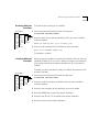
Upgrading Your LMM or LMM+
To verify that you have an LMM+ module and not an LMM module installed:
1 Check that the module’s ejector tab is labeled “LMM+”.
2 Determine the revision of your LMM+. From the top level of the
Administration Console, enter:
system display
2
COREBUILDER 6000 EXTENDED SWITCHING SOFTWARE REVISION 8.2.3
If you have an LMM+ at a revision earlier than 1.21 (for revision 1 modules)
or 2.12 (for revision 2 modules), call 3Com at 1-800-876-3266 and press
option 2. 3Com will replace your LMM+ with an LMM+ at the correct
revision, free of charge. (Contact 3Com at the same number to upgrade an
LMM to an LMM+. There is a fee for this upgrade.)
Release 8.0.0 or greater of Extended Switching Software requires a
minimum of 2 MB of memory on Ethernet/FDDI Switching Modules
(EFSMs). Memory configuration may vary. If you have an EFSM with 1 MB of
memory, you can order a memory upgrade. Contact your sales
representative.
Extended Switching
Software
Requirement
To determine the amount of memory on the EFSM, look at the lower ejector
tab label or use the system display command from the top level of the
Administration Console. EFSMs with only 1 MB of memory have blank
lower ejector tabs. EFSMs with a minimum of 2 MB of memory have “2MB”
on the lower ejector tab labels.
Release Highlights
for 8.2.3
CoreBuilder system software release 8.2.3 offers support for the following
items:
■
Software support for protocol-based VLANs
■
Support for seven RMON data groups
■
IP interface configuration change
■
Routing on FESM Modules
■
Additional RMON MIB support
■
RMON support for FDDI switched ports
For more information about this release, see “What’s New at Revision 8.2.3?”
on page 9.
CoreBuilder system software release 8.2.0 supports the following items:
Release Highlights
for 8.2.0
■
Fast Ethernet Switching Module (FESM)
■
FESM and FSM HSI Switch Engines
■
Ability to administer Fast Ethernet Ports
■
Bridge MIB support for the FESM
Updating Your System Software
■
Filter MIB
■
FTP packet filter program transfers via SNMP
■
Disconnecting an active telnet or rlogin session
■
STP linkState changes
■
CoreBuilder 6000 12-slot Chassis
3
For more information about this release, see “What’s New at Revision 8.2.0?”
on page 14.
Before You Start
Before you install your new software, read all of these release notes.
Carefully read “System Issues” on page 23 and “Known Problems” on
page 26.
The top-level menus in your Administration Console may vary from those
illustrated in these release notes depending on your level of access privilege
and on the modules you have installed in your CoreBuilder chassis.
Updating Your
System Software
You can install a new software version from any host that is running FTP
server software. The system software is distributed for both the UNIX and
the MS-DOS platforms.
The following media types are used to distribute compressed files for
software releases:
■
UNIX tar format 3 1/2 -inch, double-sided, high-density 1.44 MB diskettes
■
MS-DOS format 3 1/2 -inch, double-sided, high-density 1.44 MB diskettes
To install or upgrade your system software, you must:
1 Copy the software from the diskette to your UNIX or MS-DOS computer’s
hard disk.
2 Decompress the software.
3 Load the system software from your computer’s hard disk to flash memory
on the LMM+.
Details for these procedures are provided in the next sections.
4
COREBUILDER 6000 EXTENDED SWITCHING SOFTWARE REVISION 8.2.3
Copying System
Software to a
Hard Disk
You can copy system software to a computer that runs either a UNIX or an
MS-DOS operating system.
Copying to the UNIX Platform
The CoreBuilder software for a UNIX system is distributed on six diskettes.
Diskettes #1, #2, #3, #4, and #5 contain the CoreBuilder software. Diskette #6
contains the SNMP MIBs.
To copy the software to a UNIX hard disk, follow these instructions.
If the directory /usr/lp6000R does not exist on your computer, create the
directory before proceeding. If your /usr directory is full, use a different
directory and substitute the name of the actual directory for /usr in this
and subsequent procedures.
1 Insert diskette #1 into the disk drive. These instructions assume drive rfd0.
2 Extract the first part of the software file using the following commands:
# cd /usr/lp6000R
# tar xvf /dev/rfd0
3 Remove diskette #1 using the following command:
# eject
4 Insert diskette #2 into the disk drive and extract the second part of the file
using the following command:
# tar xvf /dev/rfd0
5 Remove diskette #2 using the following command:
# eject
6 Insert diskette #3 into the disk drive and extract the third part of the file
using the following command:
# tar xvf /dev/rfd0
7 Remove diskette #3 using the following command:
# eject
Updating Your System Software
5
8 Insert diskette #4 into the disk drive and extract the fourth part of the file
using the following command:
# tar xvf /dev/rfd0
9 Remove diskette #4 using the following command:
# eject
10 Insert diskette #5 into the disk drive and extract the fifth part of the file
using the following command:
# tar xvf /dev/rfd0
11 Remove diskette #5 using the following command:
# eject
The following files are now in your /usr/lp6000R directory:
■
README1
■
lp6000R00
■
lp6000R01
■
lp6000R02
■
lp6000R03
■
lp6000R04
■
restore_lpxR
12 Use the supplied script to decompress and restore the split file
(lp6000R00, lp6000R01, lp6000R02, lp6000R03, and lp6000R04):
# ./restore_lpxR
This procedure creates the uncompressed file lp6000R. See the README1
file for file size and checksum information.
Copying to the MS-DOS Platform
The CoreBuilder software for an MS-DOS system is distributed on four
diskettes. Install the software using the Windows 95 or Windows NT
operating system.
3Com recommends that you close all Windows programs before running this
Setup program.
6
COREBUILDER 6000 EXTENDED SWITCHING SOFTWARE REVISION 8.2.3
Installing on a Windows 95 or Windows NT Computer. To copy software
to an MS-DOS host computer’s hard disk using Windows 95 or Windows NT,
take these steps:
1 Insert diskette #1 into a disk drive. These instructions assume drive a.
2 For Windows 95, click the Windows 95 START button and choose Run.
OR
For Windows NT, from the File menu, select Run.
The system displays the Setup screen, with the system software name, and
the Setup dialog box.
3 At the command line in the Setup dialog box, enter a:setup and click OK.
A Welcome screen appears. The system prompts you to continue or to
cancel the installation. To continue, click Next. To cancel the installation and
exit the Setup program, click Cancel.
The Install Shield Wizard guides you through the rest of the installation
procedure.
This procedure creates a file folder c:\3com\lp6000R , which contains:
Loading System
Software on
the LMM+
■
IMAGE folder
■
MIBS folder
■
README.text
Before loading the system software on the LMM+, verify that the host
computer, which has a copy of the updated system software, is connected
to the CoreBuilder 6000 system.
You can load the system software into flash memory while the system is
operating. You do not need to bring the system down. After the flash install is
completed, a quick reboot puts the newly loaded software to use.
If you are loading software from a PC host, the FTP server software must be
running on the PC before you begin this procedure.
Perform NV data saves and restores only at the same software revision level.
NV data converts automatically with system software updates 8.0.2 or later.
Loading System Software on the LMM+
7
Loading 8.2.3 software into flash memory takes approximately 10 to 15
minutes to complete, depending on your network load.
To load the new software:
1 From the top level of the Administration Console, enter:
system softwareUpdate
The system prompts you for the Host IP address, Install filename, User name,
and Password. Press Return or Enter to accept the default values, which are
shown in brackets. The Password field does not display what you enter.
2 Next to Host IP address, enter the IP address of the host machine (such
as a Sun workstation or PC) from which you are installing the software.
In the example in step 5, the IP address of the host is 192.9.200.96
3 Next to Install file pathname, enter the complete path and filename.
For MS-DOS system syntax, you must precede the full path with a slash ( / ).
For example, if you are loading software from an MS-DOS host, enter the
following command at the Install file pathname prompt:
/c:\3com\lp6000R\image\lp6000R
4 Next to User name, enter your user name.
5 Next to Password, enter your password. You must enter a value for this
field, although the field does not display what you enter.
This software installation sample shows the prompts on a UNIX host:
Host IP address [192.9.200.14]: 192.9.200.96
Install file pathname [/usr/lp6000R/lp6000R]:
User name: ronnyk
Password:
Programming
Programming
Programming
.
.
.
Programming
flash memory block 1 of 25...
flash memory block 2 of 25...
flash memory block 3 of 25...
flash memory block 25 of 25...
8
COREBUILDER 6000 EXTENDED SWITCHING SOFTWARE REVISION 8.2.3
After the software is loaded, this message appears:
Installation complete.
If the CoreBuilder executable software image stored in flash memory is
corrupted (for example, when the power fails while you are updating
software), contact 3Com Technical Support. See Appendix E.
6 To reboot the system to use the newly loaded software, enter:
system reboot
You are prompted with the following message:
Are you sure you want to reboot the system (n/y) [y]:
7 At the prompt, enter y (for Yes).
You are now ready to configure management access for your system. See
the CoreBuilder 6000 Getting Started Guide.
User
Documentation
This version of software is compatible with the documentation listed here.
Some of this documentation may be available on CD-ROM. These release
notes describe any changes and additions to this documentation.
■
CoreBuilder 6000 Getting Started Guide
■
CoreBuilder 6000 Control Panel User Guide
■
CoreBuilder 6000 Operation Guide
■
Corebuilder 6000 Administration Console User Guide
■
CoreBuilder 6000 Command Quick Reference (folded card)
■
LANplex 6000 Extended Switching User Guide
The Extended Switching User Guide is shipped with Extended Switching
software.
Individual modules are shipped with their installation guides:
■
LMM+ (LANswitching Management Module +) Installation Guide
■
FCM (FDDI Concentrator Module) Installation Guide
■
EFSM (Ethernet/FDDI Switching Module) Installation Guide
■
TRSM (Token Ring Switching Module) Installation Guide
■
TMM Fast Ethernet (Tri-Media Module) Installation Guide
What’s New at Revision 8.2.3?
■
FDDI Switching Module (FSM) Guide
■
Fast Ethernet Switching Module (FESM) Guide
9
In addition, Filter Builder software and the Filter Builder Getting Started Guide
are shipped with CoreBuilder 6000 Extended Switching software.
What’s New at
Revision 8.2.3?
This section describes the new features, software enhancements, and
corrections implemented at this release.
New Features
The following new features have been added at this release.
Software Support for Protocol-based VLANs
Revision 8.2.3 offers support for protocol-based VLANs on the CoreBuilder
6000 system. Protocol-based VLANs allow you to define VLANs based on the
network protocol, including IP, IPX, AppleTalk, XNS, DECnet, X.25 Layer 3,
SNA, Banyan VINES, and NetBIOS.
This release allows you to overlap VLANs by supporting multiple protocols
per port, multiple subnetworks per port, and the spanning of Layer 3
networks across multiple ports. You can also use an external router to
communicate between VLANs.
New menus have been added to the Administration Console menu so that
you can administer protocol-based VLANs on the CoreBuilder 6000 system.
These menus allow you to:
■
Display summary or detailed information on VLANs
■
Define or modify a VLAN definition
■
Delete a VLAN definition
For more details on VLAN functionality in the CoreBuilder 6000 system, see
Appendix C, “VLANs on the CoreBuilder System” and Appendix D,
“Administering VLANs.”
Support for Seven RMON Data Groups
Revision 8.2.3 Extended Switching software supports the following RMON
data groups:
■
Group 1: Statistics — Maintains utilization and error statistics for the
monitored segment
10
COREBUILDER 6000 EXTENDED SWITCHING SOFTWARE REVISION 8.2.3
■
Group 2: History — Stores periodic statistical samples of Group 1 data for
later retrieval.
■
Group 3: Alarm — Allows a network manager to set sampling intervals and
alarm thresholds for any MIB counter or integer
■
Group 4: Host — Maintains counters of traffic to and from hosts attached
to a subnetwork
■
Group 5: HostTopN — Reports on hosts that top a list that was sorted on a
selected parameter in the Group 4 data table
■
Group 6: Matrix — Shows error and utilization data for pairs of physical
addresses
■
Group 9: Event — Allows a network manager to request traps, logs, and
alarms based on alarm events.
For more details on RMON functionality, see Appendix B, “Remote
Monitoring (RMON) Technology.”
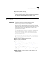
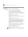
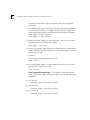
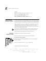
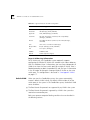
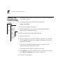
IP Interface Configuration Change
The procedure for defining an IP interface has changed in this revision.
When you define an IP interface, you specify several interface characteristics,
as well as the index for the VLAN that is associated with the interface.
You must first define a VLAN, as described in Appendixes C and D, before you
can define an associated IP VLAN interface on an EFSM, ESM, TMM, FESM, or
FSM. You can define an IP interface on an LMM+ without first configuring a
VLAN.
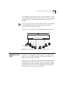
Top-Level Menu
system
1
ethernet
fddi
➧ interface
summary
tokenring
route
detail
bridge
arp
2
➧
define
➧ ip
multicast
modify
ipx
udpHelper
remove
appletalk routing
addAdvertiseme
snmp
icmpRouterDiscovery
removeAdvertise
analyzer rip
script
ping
logout
3
statistics
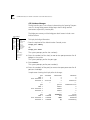
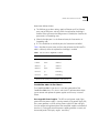
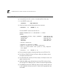
To define an IP interface:
From the top level of the Administration Console, enter:
ip interface define
Enter the slot number of the switching module or HSI switch engine
whose interface you want to define.
You are prompted for the interface’s parameters.
To accept the value in brackets, press Return or Enter at the prompt.
4 Enter the IP address of the interface.
5 Enter the subnet mask of the network to which the interface is to be
connected.
6 Enter the cost value of the interface.
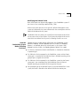
What’s New at Revision 8.2.3?
11
7 Enter the advertisement address to be used on the interface.
8 Enter the number of the VLAN whose interface you are defining.
Example:
Select IP stack by slot {1-3,5,7,9-12} [1]: 5
Enter IP address: 158.101.1.1
Enter subnet mask [255.255.0.0]: 255.255.255.0
Enter cost [1]:
Enter advertisement address(es) [158.101.1.255]:
IP VLANs:
Index
Ports
3
1-8
4
9-12
Select VLAN index: 3
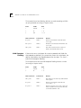
Routing on FESM Modules
This release supports IP routing and IP multicast routing on FESM modules.
For more information on IP multicast routing, see Appendix A, “IP Multicast
Routing.”
Each switching module or HSI switch engine operates as a separate IP router.
This strategy means that each non-HSI module (such as the ESM, EFSM, or
TMM-FE module) has its own interfaces, routing table, ARP cache, and
statistics, and each HSI switch engine has its own interfaces, routing table,
ARP cache, and statistics.
Additional RMON MIB Support
The FESM RMON Management Information Base (MIB) contains standard
MIB variables that are defined to collect comprehensive network statistics
and proactively alert a network administrator to significant network events.
If the embedded RMON agent operates full time, it collects data on the
correct port when an event occurs.
RMON Support for FDDI Switched Ports
Revision 8.2.3 Extended Switching software supports the following
RMON/FDDI extensions as specified in the AXON Enterprise-specific MIB:
■
axFDDI — axFDDI group 1
■
axFDDIHistory — axFDDI group 2
12
COREBUILDER 6000 EXTENDED SWITCHING SOFTWARE REVISION 8.2.3
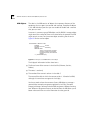
Top-Level Menu
system
display
ethernet
mode
fddi
lowLatency
tokenring
ipFragmentation
➧ bridge
ipxSnapTranslation
ip
trFddiMode
snmp
addressThreshold
analyzer
agingTime
script
stpState
logout
➧ stpFollowLinkState
stpPriority
stpMaxAge
stpHelloTime
stpForwardDelay
stpGroupAddress
srBridgeNumber
port
packetFilter
vlan
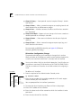
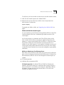
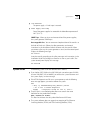
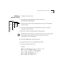
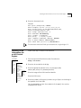
Enabling and Disabling STP Transitions on linkState Changes
The menu item stpFollowLinkState has been added. It allows you to enable
or disable Spanning Tree transitions on linkState changes. The default is
enabled.
■
When enabled and the link goes down, stpState transitions to disabled. If the
link comes up, Spanning Tree moves through its normal states.
■
When disabled, the link state has no effect on the stpState. If the link goes
down, the stpState remains in its current state.
If you are a Windows 95 client and directly connected to a CoreBuilder 6000
and running IPX, you must disable stpFollowLinkState. If you are not a
Windows 95 client, do nothing.
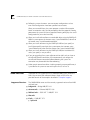
To enable or disable Spanning Tree transitions:
1 From the top level of the Administration console, enter:
bridge stpFollowLinkState
2 To enable Spanning Tree transitions, enter:
enabled
To disable Spanning Tree transitions, enter:
disabled
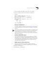
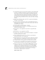
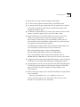
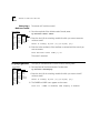
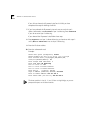
Displaying Bridge Information
Top-Level Menu
system
display
ethernet
mode ➧ summary
fddi
➧ detail
lowLatency
tokenring
multicastLimit
ipFragmentation
➧ bridge ipxSnapTranslation
stpState
ip
trFddiModestpCost
snmp addressThreshold
stpPriority
analyzer agingTime srRingNumber
script
stpState srHopLimit
logout stpPriority address
stpMaxAge
stpHelloTime
stpForwardDelay
stpGroupAddress
srBridgeNumber
➧ port
packetFilter
vlan
You can display the current setting for stpFollowLinkState. The display
includes bridge statistics (such as topology change information) and
configurations for the bridge.
To display the bridge information:
1 From the top level of the Administration console, enter:
bridge port summary
OR
bridge port detail
The system prompts you for slot number(s).
What’s New at Revision 8.2.3?
13
Sample display of bridge port information:
stpState
disabled
timeSinceLastTopologyChange
0 hrs 0 mins 0 secs
stpFollowLinkState
enabled
topologyChangeCount
0
topologyChangeFlag BridgeIdentifier
false 8000 00803elbf216
designatedRoot
0000 000000000000
stpGroupAddress
01-80-c2-00-00-00
bridgeMaxAge
20
maxAge
20
bridgeHelloTime
2
helloTime
2
bridgeFwdDelay
15
forwardDelay
15
holdTime
1
rootCost
0
rootPort
No port
priority
0x8000
agingTime
300
mode
transparent
addrTableSize
32678
addressCount
40
peakAddrCount
40
addrThreshold
32000
ipFragmentation
enabled
trFDDiMode
n/a
ipxTranslation
disabled
SRBridgeNumber
n/a
lowLatency
disabled
bufferLimit
n/a
14
COREBUILDER 6000 EXTENDED SWITCHING SOFTWARE REVISION 8.2.3
What’s New at
Revision 8.2.0?
This section describes the new features, software enhancements, and
corrections that are implemented at this release.
New Features
The following features have been added at this release.
Fast Ethernet Switching Module (FESM) Support
The Fast Ethernet Switching Module (FESM) provides high-function
switching of traffic among Fast Ethernet workstations and subnetworks over
the multigigabit high-speed interconnect (HSI) bus of the CoreBuilder 6000
system.
The FESM module has two configurations:
■
Eight 100BASE-TX ports that use RJ-45 connectors
These ports support connections to unshielded twisted pair (UTP) Category
5 media.
■
Six 100BASE-FX ports that use SC connectors
These ports support connections to multimode fiber media.
The FESM automatically learns the MAC-layer addresses of workstations
on attached subnetworks and forwards packets to their appropriate
destinations. When used with CoreBuilder Extended Switching software,
the FESM also supports routing between attached subnetworks. In
addition, the FESM fully complies with the IEEE 802.1d bridging
standard.
The FESM requires CoreBuilder 6000 software revision 8.2.0 or greater. This
software, in turn, requires that you install one of the following LANswitching
Management Module Plus (LMM+) versions in system slot 1:
■
Revision 1.21 or greater of the revision 1 LMM+
■
Revision 2.12 or greater of the revision 2 LMM+
CAUTION: If you attempt to run CoreBuilder system software 8.2.0 or greater
on an earlier revision of the LMM+, the system fails to reboot when you turn
it on.
What’s New at Revision 8.2.0?
15
To verify that you have an LMM+ module and not an LMM module installed:
1 Verify that the module’s ejector tab is labeled “LMM+”.
2 Determine the revision level of your LMM+. From the top level of the
Administration Console, enter:
system display
To upgrade your LMM or LMM+, see “Upgrading Your LMM or LMM+” on
page 1.
FESM and FSM HSI Switch Engine
You can combine the Fast Ethernet Switching Module (FESM) and the FDDI
Switching Module (FSM) into a multiboard high-speed interconnect (HSI)
switch engine.
An HSI switch engine is a combined set of FSMs, FESMs, or both, which,
when inserted into the HSI bus according to specific configuration rules,
operates as a single switch. Multiple FSMs and FESMs in a single HSI switch
engine form a bridge out of the combined set of external ports on all
modules in that switch engine. As a new module is added to an existing HSI
switch engine, configuration information for the existing HSI switch engine
is added to the new module. You must manually configure any port-specific
information.
Ability to Administer Fast Ethernet Ports
New menus on the Administer menu allow you to administer Fast Ethernet
ports on the Fast Ethernet Switching Module (FESM) and the Tri-Media Fast
Ethernet Module (TMM-FE). You can now configure Fast Ethernet ports to
support:
■
Full-duplex operation
■
Intelligent flow management (IFM)
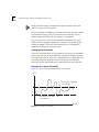
Full-duplex operation. By default, FESM and TMM Fast Ethernet ports
operate in half-duplex mode. In this mode, data flows through the port in
only one direction at a time. When you change this operating mode to
full-duplex, the port transmits and receives data at the same time
through two separate channels.
16
COREBUILDER 6000 EXTENDED SWITCHING SOFTWARE REVISION 8.2.3
Full-duplex mode eliminates both the link’s collision domain and the
need for collision detection. As a result, full-duplex point-to-point links
can be much longer than half-duplex links.
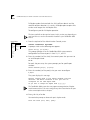
To configure a port for full-duplex operation:
The items available on the top-level menus in this section vary depending on
your level of access and on the modules installed in your CoreBuilder 6000
chassis.
Top-Level Menu
system
➧ ethernet summary
fddi
detail
tokenring➧ fastEthernet ➧ duplexMode
ifm
bridge
label
ip
portState
ipx
appletalk
snmp
analyzer
script
logout
1 From the top level of the Administration Console, enter:
ethernet fastEthernet duplexMode
s
A prompt similar to the following one appears:
Select slot(s) (10-12|all):
This prompt indicates that the CoreBuilder 6000 system contains
configurable Fast Ethernet ports in slots 10, 11, and 12.
2 Enter the number(s) of the slot(s) that contain ports that you want to
set to full-duplex mode:
10-12
For each slot you enter, the system prompts you for specific port
numbers:
Select Ethernet port(s) (1-8,all):
3 Enter the number(s) of the port(s) that you want to configure:
1,2,5-7
The system displays this message:
Warning: Changing mode to full duplex disables collision
detection. The device connected to this port must be
configured for the same duplex mode.
Do you want to change the duplex mode (n,y) [y]:
The CoreBuilder 6000 system does not support autonegotiation of duplex
mode between devices. You must configure any device attached to this port
to the same duplex mode as the port.
4 Enter y for Yes, n for No.
You receive the prompt to select each port’s duplex mode:
Enter new value (full, half) [half]:
What’s New at Revision 8.2.0?
17
5 Enter full to set the port to full-duplex mode or half to set the port
to half-duplex mode.
Default
The port’s current setting is indicated in brackets. To select this default,
press Return. This action leaves the port duplex mode unchanged.
6 Repeat steps 4 and 5 to configure all the selected ports in all the
selected slots.
Changing the mode to full-duplex disables collision detection on these ports.
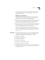
Intelligent Flow Management (IFM). Intelligent flow management
(IFM) is a congestion control mechanism that is built into the
CoreBuilder system. You should implement IFM on any Fast Ethernet
port that has a high volume of traffic. By default, IFM is enabled on
CoreBuilder module ports.
Congestion is caused when one or more devices send traffic to an already
congested port. If the port is connected to another CoreBuilder system or to
an end station, IFM minimizes packet loss and inhibits the sending device
from generating more packets until the congestion ends.
Intelligent flow management is supported only on half-duplex ports. It is
disabled on port that are configured for full-duplex mode. 3Com
recommends that you disable IFM on network segments that are connected
to repeaters.
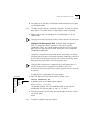
To apply IFM to a half-duplex Fast Ethernet port:
Top-Level Menu
system
➧ ethernet summary
fddi
detail
tokenring➧ fastEthernet duplexMode
➧ ifm
bridge
label
ip
portState
ipx
appletalk
snmp
analyzer
script
logout
1 From the top level of the Administration Console, enter:
ethernet fastEthernet ifm
s
A prompt similar to the following one appears:
Select slot(s) (10-12|all):
This prompt indicates that the CoreBuilder 6000 system contains
configurable Fast Ethernet ports in slots 10, 11, and 12.
2 Enter the number(s) of the slot(s) that contain ports that you want to
set to IFM mode:
10-12
Default
To select the default all, press Return.
18
COREBUILDER 6000 EXTENDED SWITCHING SOFTWARE REVISION 8.2.3
For each slot that you enter, the system asks for specific port numbers:
Select Ethernet port(s) (1-8,all):
3 Enter the number(s) of the port(s) that you want to configure:
1,2,5-7
Default
To select the default all, press Return.
Enter enable or disable to select the IFM mode for each selected port:
Enter new value (disabled, enabled) [disabled]:
4 Enter enabled to set the port to IFM mode or disabled to deactivate IFM
for the port.
Default
To select the port’s current setting, shown in brackets, press Return. This
action leaves the port setting unchanged.
5 Repeat step 4 to configure all selected ports in all selected slots.
Bridge MIB Support for the FESM
FESM support has been added to the Bridge MIB.
Filter MIB Support
To support Filter Builder software, this revision adds the Filter MIB (address
group, port group, and bridge packet filter program). See the Filter Builder
Getting Started Guide, which is shipped with the Filter Builder software, for
more information about the Filter Builder product.
FTP Packet Filter Program Transfers via SNMP
You can now use File Transfer Protocol (FTP) to transfer a user-defined
packet filter program from a remote server to a CoreBuilder switching
module through the SNMP lpsFtTable MIB.
Disconnecting an Active telnet or rlogin Session
Modifications to the telnet and rlogin features of the CoreBuilder 6000
system now allow you to preempt users by forcing a disconnection. This
administrative feature requires that you use the system Administer
password at the Administration Console.
The rlogin usage is identical to the telnet usage. Simply substitute rlogin
wherever you see telnet.
What’s New at Revision 8.2.0?
19
telnet Implementation. When you attempt to use the telnet command to
enter a system that is being used by another telnet connection, the system
displays:
Sorry, this system is engaged by another telnet session.
Host IP address: xxx.xxx.xxx.xxx
Logout the other telnet session? (Y/N) y
Enter Password: correctpassword
The first telnet session is disconnected and the system displays:
LOGGING OUT the other telnet session.
You can then connect in the usual manner.
CAUTION: When you preempt a telnet or rlogin session in this manner, the
current session user receives no notice that the session will be disconnected.
If you enter an incorrect password, the system displays:
Incorrect password. Disconnecting.
The system disconnects after it receives three incorrect attempts at the
Administer-level password.
If you respond n to the request to disconnect, your session disconnects
and the original connection remains established. The system displays:
Disconnecting
If you respond y at the Logout the other telnet session? prompt and
it is not accepted, it is probably because of the telnet configuration on the
UNIX host. To force the system to accept your response to the prompt,
follow these steps:
1 Escape to the telnet session by pressing Ctrl+}
2 Set the cr/lf option by entering either of these commands:
set crlf
OR
toggle crlf
Press Return or Enter to redisplay the prompt. Your response should now be
accepted.
20
COREBUILDER 6000 EXTENDED SWITCHING SOFTWARE REVISION 8.2.3
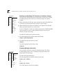
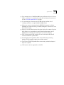
STP linkState Changes
The linkState of a port is now a factor in determining the Spanning Tree port
state. This change helps prevent bridge loops when making network
connections to previously inactive ports.
Top-Level Menu
system
display
ethernet
mode ➧ summary
fddi
➧ detail
lowLatency
tokenring
multicastLimit
ipFragmentation
➧ bridge ipxSnapTranslation
stpState
ip
trFddiModestpCost
snmp addressThreshold
stpPriority
analyzer agingTime srRingNumber
script
stpState srHopLimit
logout stpPriority address
stpMaxAge
stpHelloTime
stpForwardDelay
stpGroupAddress
srBridgeNumber
➧ port
packetFilter
vlan
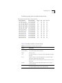
The bridge port summary and the bridge port detail screens include a new
linkState column.
To display the bridge information:
1 From the top level of the Administration Console, enter:
bridge port summary
OR
bridge port detail
The system prompts you for slot number(s).
2 Enter the number(s) of the slot(s) or all to view port parameters for all
bridges in the system.
The system prompts you for the port type.
3 Enter Ethernet
The system prompts you for port number(s).
4 Enter the number(s) of the port(s) or all to view port parameters for all
ports on the bridge.
Sample screen showing the display after the changes:
port
FDDI 1
Fast Ethernet 1
Ethernet 2
...
port
FDDI 1
Fast Ethernet 1
Ethernet 2
...
port
FDDI 1
Fast Ethernet 1
Ethernet 2
rxFrames
0
0
59243130
...
stp
enabled
enabled
enabled
rxDiscards
0
0
0
...
portId
0x8001
0x8002
0x8003
...
linkState
n/a
down
up
txFrames
0
0
866810375
...
fwdTransitions
0
0
0
...
state
forwarding
disabled
forwarding
What’s New at Revision 8.2.0?
21
Note these additional items:
■
■
■
The linkState up or down settings apply to Ethernet and Fast Ethernet
ports, not to FDDI ports, and only when the stpState for the bridge is
enabled. If the stpState on the Bridge menu is disabled, the State for the
port remains in forwarding state.
When the bridge port is in the Removed state, the State remains in
forwarding state.
If STP is disabled on an individual port, the State remains disabled.
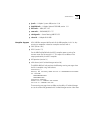
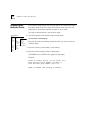
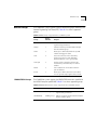
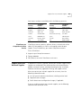
Table 1 describes the port states and how they relate to the linkState. This
table is valid only when the stpState for the bridge is enabled.
Table 1 Port States When stpState Is Enabled
If STP is
and linkState is
Then Port State is
enabled
up
blocking or forwarding*
enabled
down
disabled
disabled
up
disabled
disabled
down
disabled
removed
up
forwarding
removed
down
forwarding
*The Port State is either blocking or forwarding. The final state
depends on the Spanning Tree configuration of the network.
CoreBuilder 6000 12-Slot Chassis
The CoreBuilder 6000 12-slot chassis is the latest generation of the
CoreBuilder 6000 chassis. This chassis and the 8.2.3 software release allow
you to remove and replace the power supplies and fan trays in case of
failure.
Hot-swappable Power Supplies. The LED on each power supply lights
green when the power supply is running correctly. If the power supply fails,
the system generates a sound and the power supply LED does not light.
You can remove and replace either of the two power supplies at the back of
the chassis. (Turning off one of the power supplies generates a sound, and
the control panel LCD displays Input Failure.)
22
COREBUILDER 6000 EXTENDED SWITCHING SOFTWARE REVISION 8.2.3
To remove a faulty power supply and replace it with a new unit, follow
these steps:
1 Turn off the power supply according to the safety and removal procedures
in the Installation Guide that is shipped with the new power supply. The
system control panel displays the following message (where n designates
power supply 1 or power supply 2):
Power Supply n: Input Failure
2 Remove the power supply. The system generates a sound, and the system
control panel displays the following message:
Power supply n extracted.
3 Insert the new power supply, following the safety warnings and instructions
in the Installation Guide that comes with the new power supply. The system
displays this message:
Inserted
This message is immediately overwritten with:
Input Failure
4 Turn on the power supply. The system generates a sound and the system
control panel displays this message:
Input restored
Power Supply Warning Messages. This release of system software now
displays these power supply warning messages on the control panel when
appropriate:
■
+5V Failure
The power supply +5-volt input has failed.
■
+12V Failure
The power supply +12-volt input has failed.
■
+5V Restored
The power supply +5-volt input is restored.
System Issues
■
23
+12V Restored
The power supply +12-volt input is restored.
■
Power Supply Over Temp
One of the power supplies has exceeded the allowable temperature of
90 °C (194 °F).
SNMP Traps. When you insert and extract either of the power supplies,
the system generates SNMP traps.
Hot-swappable fans. You can remove and replace either of the two fans at
the back of the chassis. Follow the safety precautions and removal
instructions in the Installation Guide that comes with the new fan. When
you remove a fan tray, the system generates a sound, and the control panel
displays the following message:
Fan Failure
Insert the new fan according to the safety messages and instructions in the
Installation Guide. The fan begins to function as soon as you install it. The
system control panel displays this message:
Fan Restored
System Issues
The following system issues are identified at this release:
■
If you define a DEC VLAN and an XNS VLAN, plus two other types of VLAN’s
that are SNA, VINES, X25, or NetBIOS, you exhaust the system resources and
the system displays an error message.
■
If the FESM diagnostic test fails on a system power-up and the following
error message appears, you need to reboot the system:
FAIL
-- Test[ 3 ]: FSM/FESM Powerup Diag ( MAC Test ) failed.
-- B3 in slot 10 FAILED diagnostics
Diagmgr
: Diagnostics failed for slot 10, error 2
■
The first line in a user-defined packet filter must contain the name
definition for that packet filter. Example:
Name Òforward IP framesÓ
This filter line indicates that this packet filter forwards IP frames.
■
The system software does not support hot-swapping of Fast Ethernet
Switching Modules (FESMs) and FDDI Switching Modules (FSMs).
24
COREBUILDER 6000 EXTENDED SWITCHING SOFTWARE REVISION 8.2.3
■
3Com recommends that you hot-swap one module at a time (except FESMs
and FSMs, as described in the previous System Issue). After you hot-swap
one module, wait until the system completes full initialization before you
install another module. One indication that initialization is complete is that
the Administration Console prompt appears. Under certain circumstances,
hot-swapping during initialization can cause a cold system boot, disrupting
bridging.
■
When the first FDDI MAC address of an FSM is assigned to the backplane,
FDDI ports are renumbered.
■
A maximum of four interfaces per system may have RMON group Host or
RMON group Matrix enabled. A maximum of two interfaces per module can
have RMON groups enabled.
■
The ESM supports only RMON groups 1 through 4.
■
Packet filtering on the transmit path is not available on frames that are
routed by the CoreBuilder system.
■
Roving Analysis is not supported on a port with an assigned IP router
interface.
■
Roving Analysis is not supported on the FESM.
■
A Roving Analysis frame over a remote TMM-FE connection is truncated if
the frame is greater than 1495 bytes.
■
When configuring Roving Analysis on an ESM, the system accepts an
unknown MAC address as the analyzer port.
■
Bridging performance and routing performance are degraded on a Roving
Analysis monitor port, or if RMON Host or Matrix groups are configured.
■
EFSM packet filters can access packet data through byte 64 in packet.
■
A maximum of 254 unique RMON Owner descriptions (etherStatsOwner,
historyControlOwner, alarmOwner, and eventOwner) can be configured.
■
When you install revision 8.2.0 of CoreBuilder 6000 Intelligent Switching
software on a LMM+ that is running revision 8.2.3 Extended Switching
software and you have defined non-IP VLANs, you must reset NVRAM
immediately after installing the 8.2.0 Intelligent Switching software into
flash memory. Immediately after the Console displays the message
Installation complete, enter this command:
system nvdata reset
System Issues
25
■
If you attempt to run CoreBuilder 6000 system software revision 8.2.3 on an
LMM+ at revision 2.11 or earlier, the system fails to reboot when you turn it
on. See “Hardware Dependencies” on page 1.
■
You can configure a maximum total of 100 routing interfaces for all
switching modules in a single CoreBuilder 6000 system.
■
When your system is connected to the MBONE (the Internet’s multicast
backbone) and multicast routing is enabled, configure a maximum of 3 slots
for multicast routing.
■
When you use the Administration Console to display all instances of a given
MAC address in a mixed token ring and Ethernet environment, use the
find command for both the noncanonical and canonical formats.
■
ESMs do not support IGMP snooping. To avoid unwanted traffic, filter IP
multicast traffic with a packet filter.
■
The Ethernet Switching Module (ESM) and the Token Ring Switching
Module (TRSM) incorrectly report transmit filter statistics.
■
The ESM and TRSM FDDI packet filters cannot access packet data beyond
byte 16 in a packet.
■
VLAN statistics are not supported on the ESM.
26
COREBUILDER 6000 EXTENDED SWITCHING SOFTWARE REVISION 8.2.3
Known Problems
The following software problems are identified at this release:
■
To compile lpv2.mib with a version 2 compiler, perform these steps:
1 In the IMPORTS section, add:
RowStatus
FROM SNMPv2-TC
2 A few lines below, add the following RowStatus comment:
-- RowStatus
::==
INTEGER (1..6)
The new IMPORTS section now looks like this:
LANPLEX-SYSTEMS-MIB-1-4-1 DEFINITIONS ::= BEGIN
IMPORTS
enterprises, Counter, Gauge, IpAddress
DisplayString
OBJECT-TYPE
RowStatus
TRAP-TYPE
FROM
FROM
FROM
FROM
FROM
RFC1155-SMI
RFC1213-MIB
RFC-1212
SNMPv2-TC
RFC-1215
-- Textual conventions
-- RowStatus as defined in SNMPv2
-- Refer to rfc1443.txt for concise definition
-- This is a place holder until lp.mib is fully compliant
with SNMPv2
-- RowStatus
::==
INTEGER (1..6)
■
Do not create port groups and port group filters on the FESM or FSM.
■
The FESM and TMM-FE rxFrames, txFrames, rxBytes, and txBytes statistics
can report inaccurate values.
■
The FESM FDDI MAC rxFrames, txFrames, rxBytes, and txBytes statistics can
report inaccurate values.
■
CoreBuilder 6000 system software does not route FDDI multicast frames
that are larger than 1500 bytes (that is, frames that require fragmentation).
■
The NVRAM conversion for SNMP traps does not adjust correctly after you
install CoreBuilder software revision 8.2.3. Verify that the appropriate traps
are enabled.
Known Problems
27
■
Roving Analysis cannot monitor outgoing routed packets.
■
FCS error statistics report inaccurate values on the TMM-FE’s port.
■
You cannot modify the port specification of an IP interface that is defined
on the LMM+ module. To modify the port specification, remove the IP
interface and define it again.
■
An NVDATA save procedure fails if it occurs at the same instant that a MAC
address is learned or aged out of the slot’s MAC address table.
■
If both the Ethernet and the FDDI interfaces have the same class of IP
address, their subnet masks must be the same, even though the
Administration Console allows you to enter different subnet masks for
these interfaces. If you enter different subnet masks, the system fails when
you attempt to remove one of the interfaces.
In the following example, the FDDI and the Ethernet interfaces both have
class B IP addresses, and both have the same subnet mask:
FDDI interface 158.101.101.1 Subnet mask: 255.255.0.0
Ethernet interface: 158.101.20.1 Subnet mask: 255.255.0.0
Do not assign different subnet masks to these interfaces (such as
255.255.255.0 and 255.255.0.0) if they have the same class of IP address.
■
Changing the port speed or port mode before setting a system baseline on
the TRSM can cause incorrect Token Ring port and bridge port statistics.
■
Some bridge port statistics are not counted on the TRSM’s Token Ring ports.
The following statistics report 0 in the bridge port display for Token Ring
ports on the TRSM: rxDiscard, rxFloodUcasts, rxForwardMcasts, and
rxForwardUcasts.
■
When running large scripts, you can receive the following message after the
script is complete:
Received ftpCommand Quit not completed errno 421
To be sure that the script has run successfully, verify that the last two
commands in the script have run successfully.
28
COREBUILDER 6000 EXTENDED SWITCHING SOFTWARE REVISION 8.2.3
■
Performing a manual nvdata restore restores configurations to slots
even if the configurations have been specified not to restore.
When you restore NV data, the system proposes a method of restoration
based on restoration rules. You are prompted to load the proposal. Entering
yes restores the system NV data as proposed. Entering no displays the saved
configuration for you to load manually.
■
When you install software from an unreachable device using the SNMP lpsFt
MIB, the system reports the incorrect status “statusFileNotFound”, rather than
the correct status “statusRemoteUnreachable”.
■
When you install software using the SNMP lpsFt MIB and you specify an
invalid Username/Password pair, the system reports the incorrect status
”statusFileNotFound”, rather than the correct status “statusUserAuthFailed”.
■
When you install software using the SNMP lpsFt MIB, the installation fails
unless you specify a user password.
■
If you are upgrading from system software revision 8.0.2, and you have an
out-of-band Ethernet connection, 3Com recommends you remove the
out-of-band Ethernet connection before rebooting the system. The
connection may be reestablished after rebooting.
■
Under certain network conditions involving errored source routed frames, it
is possible for the system to reset with a panic line 55 or line 78.
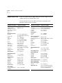
SNMP MIB Files
SNMP MIB files are shipped with the CoreBuilder 6000 system software as
ASN.1 files on one of the software diskettes. Copies of ASN.1 files are
provided for each of the compilers described in “Compiler Support.”
Supported Versions
The SNMP MIB file names and the currently supported version of each MIB
are listed here:
■
bridge.mib — Bridge MIB, RFC 1493
■
ethernet.mib — Ethernet MIB, RFC 1398
■
fddiSmt7.mib — FDDI SMT 7.3 MIB, RFC 1512
■
filter.mib
■
if.mib — If MIB, RFC 1573
■
lpsFt.mib
SNMP MIB Files
■
lp.mib — LANplex Systems MIB, version 1.3.0
■
lpOpFddi.mib — LANplex Optional FDDI MIB, version 1.2.1
■
mib2.mib — MIB-II, RFC 1213
■
rmon.mib — RMON MIB, RFC 1757
■
srbridge.mib —Source Routing MIB RFC1525
■
vlan.mib — LANplex VLAN MIB
Compiler Support
29
ASN.1 MIB files are provided for each of the MIB compilers in this list. Any
warnings or exceptions related to a compiler are listed with it.
■
SMIC (version 1.0.9)
■
MOSY (version 7.1)
For the MIB file lpOpFddi.mib, the MOSY compiler reports warnings for
counter names that do not end in “s”. This report has no effect on the
output produced by the MOSY compiler.
■
HP Openview (version 3.1)
■
mib2schema (with SunNet Manager version 2.0)
The MIB file fddiSmt7.mib produces the following warning messages when
the file is compiled using mib2schema:
Translating....
Warning: The following INDEX entries in fddimibMACCountersTable
not resolved:
fddimibMACSMTIndex
fddimibMACIndex
Translation Complete.
Schema file in ÒfddiSmt7.mib.schemaÓ
Oid file in ÒfddiSmt7.mib.oidÓ
These warning messages have no effect on the ability of SunNet Manager
to use the schema file generated with SunNet Manager versions 2.0 or later.
30
COREBUILDER 6000 EXTENDED SWITCHING SOFTWARE REVISION 8.2.3
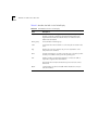
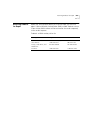
Revision History
Table 2 describes the previous releases of the CoreBuilder 6000 Extended
Switching software.
Table 2 Revision History for CoreBuilder 6000 Software
Revision Number
Description of Release
8.2.1/8.2.3
New features:
8.2.0
■
Software support for protocol-based VLANs
■
Support for seven RMON data groups
■
IP interface configuration change
■
Routing on FESM Modules
■
Additional RMON MIB support
■
RMON support for FDDI switched ports
New features:
■
Fast Ethernet Switching Module (FESM) support
■
FESM and FSM Switch Engine
■
Ability to administer Fast Ethernet Ports
■
Bridge MIB support for the FESM
■
Filter MIB support
■
FTP packet filter program transfers via SNMP
■
Disconnecting an active telnet or rlogin session
■
STP linkState changes
■
CoreBuilder 6000 12-slot Chassis
8.0.2
■
Updated system diagnostics
8.0.1
New feature:
■
(continued)
Support for IP routing on the FDDI Switching Module (FSM)
Revision History
31
Table 2 Revision History for CoreBuilder 6000 Software (continued)
Revision Number
Description of Release
8.0.0
New features:
7.0.0
■
Support for the FDDI Switching Module (FSM)
■
Support for the EFSM TP-DDI Module
■
Support for RMON
■
RMON MIB support added
■
State field added to interface display
■
System menu item upTime added
■
New FDDI MAC statistic rxErrors
■
New fields added to FDDI MAC summary and detail displays
■
Configurable Source Route hop count limit
■
LANplex® MIB support updates
■
Bridge MIB support added for the FSM
■
New If MIB added
New features:
■
■
■
■
Support for IP Multicast on the Ethernet/FDDI Switching
Module (EFSM)
Support for the IBM Spanning Tree Protocol on the Token
Ring Switching Module (TRSM)
Support for configuring the Spanning Tree Protocol (STP)
group address
■
Support for Token Ring and Source Routing MIBs
■
Menu change (ip forwarding to ip routing)
■
Configuration change to enable or disable routing
■
■
(continued)
Support for the Tri-Media Module (TMM)
Support for telnet and rlogin session termination after a
user-specified time interval
Support for 64 IP static routes on each EFSM
32
COREBUILDER 6000 EXTENDED SWITCHING SOFTWARE REVISION 8.2.3
Table 2 Revision History for CoreBuilder 6000 Software (continued)
Revision Number
Description of Release
6.0.0
New feature:
■
5.0.0
4.3.0
New features:
■
Support for LMM+ management module
■
Support for IPX Routing
■
Support for AppleTalk Routing
New features:
■
UDP Helper
■
IPX Snap Translation Option
■
Support for EFSM Type 1, 10BASE-2 (BNC) module
■
4.1.0
Support for Single Mode Fiber (SMF) on the FCM module
■
Support for the 48-volt power supply
New features:
■
(continued)
Support for EFSM Type 2, 10BASE-T (RJ-45) and 10BASE-FL
(FOIRL) option modules with SAS FDDI (MIC) ports
■
■
3.1.9
Support for the Token Ring Switching Module (TRSM)
Support for EFSM Type 1, 10 BASE-T (RJ-21, Telco), 10BASE-T
(RJ-45), and 10BASE-FL (FOIRL)
Roving Analysis for Ethernet network monitoring (ESM and
EFSM)
■
Support for Multiple SNMP Agents
■
Multistation Mode
■
FDDI Backplane Paths
■
Enhanced Administration Console User Guide
Maintenance release
Revision History
33
Table 2 Revision History for CoreBuilder 6000 Software (continued)
Revision Number
Description of Release
3.1.7
Maintenance release
MIB support removed:
■
■
3.1.5
3.1.1
3.0.1
The LANplex SNMP MIB traps,
lpBridgePortAddressLearnedEvent and
lpBridgePortAddressForgottenEvent, are no longer supported.
New feature:
■
3.1.4
The Ethernet MIB attributes, requestedEnabledPaths and
enabledPaths, are no longer supported.
Support for SMT MIB path attribute Ring Latency
New features:
■
ESM 10BASE-2 (BNC) media support
■
IP advertisement address configuration support
New features:
■
IP routing functionality
■
TP-DDI media support
■
Nonvolatile data save and restore functionality
New feature:
■
Baselining of Ethernet and FDDI statistics functionality
34
COREBUILDER 6000 EXTENDED SWITCHING SOFTWARE REVISION 8.2.3
IP MULTICAST ROUTING
A
Overview
This appendix describes how to set up your CoreBuilder ™ 6000 system to
use IP multicast routing. Before you define any IP multicast interfaces, you
should have previously defined IP interfaces and routes as described in the
LANplex® 6000 Extended Switching User Guide.
This appendix includes information on how to display or configure the
following parameters:
■
Enabling and disabling the Distance Vector Multicast Routing Protocol
(DVMRP)
■
Enabling and disabling the Internet Group Membership Protocol (IGMP)
■
Administering IP multicast interfaces
■
Administering multicast tunnels
■
Route display
■
Cache display
A-2
APPENDIX A: IP MULTICAST ROUTING
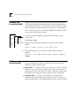
Enabling and
Disabling DVMRP
Top-Level Menu
system
ethernet
interface
fddi
➧ dvmrp
route
tokenring arp
igmp
bridge
➧ multicast interfaces
➧ ip
udpHelper tunnel
ipx
routeDisplay
routing
appletalk icmpRouterDiscovery
cacheDisplay
snmp
rip
analyzer
ping
script
statistics
logout
DVMRP is the simple Distance Vector Multicast Routing Protocol, similar to
the IP Routing Information Protocol. Multicast routers exchange distance
vector updates that contain lists of destinations and the distance in hops to
each destination. The routers maintain this information in a routing table.
To run multicast routing, you must enable DVMRP, which enables it on all IP
interfaces that have not been disabled.
1 To enable or disable DVMRP, from the top level of the Administration
Console, enter:
ip multicast dvmrp
2 Enter the slot of the switching module for which you want to enable
DVMRP.
Select IP stack(s) by slot (2,3,7,9-12|all) [12]:
3 The interface prompts you to enable or disable DVMRP. The default is
disabled.
Slots 9-12 - Enter DVMRP mode (disabled, enabled) [disabled]:
enabled
Enabling and
Disabling IGMP
IGMP enables a router or switch to determine whether group members
exist in a subnetwork, or “leaf,” of the Spanning Tree. It uses two search
methods to make this determination:
■
Query mode — The router or switch with the lowest IP address in the LAN
broadcasts a query to all other members of the subnetwork to determine
whether they are also in the group. End-stations respond to the query with
IGMP packets, which report the multicast group to which they belong.
■
Snooping mode — A router or switch performs dynamic multicast
filtering based on IGMP snooping. This procedure ensures that multicast
packets are flooded only to the appropriate ports within a routing interface.
Administering IP Multicast Interfaces
A-3
When you select the IGMP option, the interface prompts you to enable or
disable IGMP snooping mode and IGMP query mode. Both are enabled by
default. Under most conditions, IGMP snooping mode and IGMP query
mode should remain enabled.
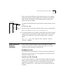
Top-Level Menu
system
ethernet interface
dvrmp
fddi
route
➧ igmp
tokenring arp
bridge ➧ multicast
interface
➧ ip
udpHelper tunnel
routeDisplay
ipx
routing
cacheDisplay
appletalk icmpRouterDiscovery
snmp
rip
analyzer
ping
script
statistics
logout
To enable or disable IGMP, from the top level of the Administration Console,
enter:
ip multicast igmp
1 Enter the slot of the switching module for which you want to enable IGMP.
Select IP stack(s) by slot (2,3,7,9-12|all) [12]:
2 The interface prompts you to enable or disable IGMP query mode and IGMP
snooping mode. If an IP interface has been defined on an EFSM or a TMM
module in the CoreBuilder system, IGMP snooping mode is enabled by
default.
Slots 9-12 - Enter IGMP snooping mode (disabled, enabled)
[enabled]: enabled
Administering IP
Multicast
Interfaces
The IP multicast interface selections allow you to enable and disable
multicast characteristics on previously defined IP interfaces. A multicast
interface has three characteristics, explained next.
DVMRP Metric Value
The DVMRP metric value determines the cost of a multicast interface. The
higher the cost, the less likely it is that the packets will be routed over the
interface. The default value is 1.
Time To Live (TTL) Threshold
The TTL threshold determines whether the interface will forward multicast
packets to other switches and routers in the subnetwork. If the interface TTL
is greater than the packet TTL, then the interface does not forward the
packet. The default value is 1, which means that the interface will forward
all packets.
A-4
APPENDIX A: IP MULTICAST ROUTING
Rate Limit
The rate limit determines how fast multicast traffic can travel over the
interface in kilobytes per second. Multicast traffic may not exceed this rate
limit or the CoreBuilder system will drop packets in order to maintain the
set rate. The default is set to 0, which implies no rate limit. In all other
instances, the lower the rate limit, the more limited the traffic over the
interface.
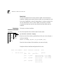
Displaying
Multicast Interfaces
Top-Level Menu
system interface
dvmrp
ethernet route
igmp ➧ display
fddi
arp
tokenring➧ multicast ➧ interface enable
bridge udpHelper tunnel disable
routeDisplay
➧ ip
routing
cacheDisplay
ipx
icmpRouterDiscovery
appletalk rip
snmp
ping
analyzer statistics
script
logout
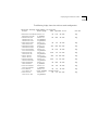
To display a multicast interface:
1 From the top level of the Administration Console, enter:
ip multicast interface display
2 Enter the slot of the switching module from which you want to display a
multicast interface.
Select IP stack(s) by slot (2,3,7,9-12|all) [12]:
Enter the index numbers of the interfaces you want to display.
Example multicast interface configuration for the slot:
Index
1
Local Address
158.101.112.32
Metric
Threshold
1
pkts
1
in:0
port
3
port
3 groups
port
4 groups
peers
RateLimit
0
pkts out:0
State
queries
158.101.112.204
158.101.112.202
224.2.127.255
224.2.143.24
224.2.143.24
224.2.127.225
(3.6) (0x8e)
(3.6) (0x8f)
(3.6) (0x8e)
Administering IP Multicast Interfaces
Disabling Multicast
Interfaces
Top-Level Menu
system
ethernet interface
route
dvmrp
fddi
igmp display
tokenring arp
bridge ➧ multicast ➧ interface enable
udpHelper tunnel ➧ disable
➧ ip
routing
routeDisplay
ipx
cacheDisplay
appletalk icmpRouterDiscovery
rip
snmp
analyzer ping
statistics
script
logout
A-5
To disable multicast routing on an interface:
1 From the top level of the Administration Console, enter:
ip multicast interface disable
2 Enter the slot(s) of the switching module for which you want to disable a
multicast interface.
Select IP stack by slot (2,3,7,9-12|all) [12]:
3 Enter the index number of the IP interface you want to disable.
Enter an IP interface index {1-2}:
The interface is disabled.
Enabling Multicast
Interfaces
Top-Level Menu
system
ethernet interface
route
dvmrp
fddi
igmp display
tokenring arp
bridge ➧ multicast ➧ interface➧ enable
udpHelper tunnel disable
➧ ip
routing
routeDisplay
ipx
cacheDisplay
appletalk icmpRouterDiscovery
rip
snmp
analyzer ping
statistics
script
logout
Multicast routing is enabled on all existing IP interfaces when you have not
specifically disabled it. You can use this option to change the characteristics
of an existing interface or to enable an interface that you had previously
disabled.
To enable a multicast interface or modify the multicast characteristics of an
existing IP interface:
1 From the top level of the Administration console, enter:
ip multicast interface enable
2 Enter the slot of the switching module for which you want to enable a
multicast interface.
3 Enter the index number(s) of the interface(s) you want to enable.
4 Enter the DVMRP metric value of the chosen interface(s).
5 Enter the Time To Live (TTL) threshold of the chosen interface(s).
6 Enter the rate limit of the chosen interface(s).
A-6
APPENDIX A: IP MULTICAST ROUTING
Example:
Select IP stack by slot (2,3,7,9-12|all) [12]:
Enter an IP interface index [1]: 2
Enter Interface DVMRP metric [1]: 1
Enter Interface TTL threshold [1]:
Enter interface rate limit in KBits/sec [0]:
Administering
Multicast Tunnels
A multicast tunnel allows multicast packets to cross several unicast routers
to a destination router that supports multicast. A tunnel has two end points.
The local end point is associated with an interface on the CoreBuilder router.
When you define the tunnel, you specify the associated index on the local
CoreBuilder router and then the characteristics of the tunnel. Tunnel
characteristics are the same as those of an interface. You also specify the IP
address of the remote multicast router.
Not all multicast configurations require a tunnel. The only configurations
that require a tunnel are those that require a connection between two
multicast internetworks through one or more unicast routers.
Displaying
Multicast Tunnels
To display the IP multicast tunnels on the router:
1 From the top level menu of the Administration Console, enter:
Top-Level Menu
system
ethernet interface
dvmrp
route
fddi
igmp ➧ display
tokenring arp
bridge ➧ multicast interface define
remove
udpHelper➧ tunnel
➧ ip
routing routeDisplay
ipx
cacheDisplay
appletalk icmpRouterDiscovery
rip
snmp
analyzer ping
statistics
script
logout
Index
1
ip multicast tunnel display
2 Enter the slot of the switching module for which you want to display a
multicast interface.
Select IP stack(s) by slot (2,3,7,9-12|all) [9]:
Example IP multicast tunnel configuration:
Local Address
Remote Address Metric Threshold RateLimit State
158.101.112.204 137.39.229.98 2
255
pkts in:320069 pkts out:0
peers 137.39.229.98
500
(3.8) (0xe)
Administering Multicast Tunnels
Defining a
Multicast Tunnel
A-7
To define a multicast tunnel:
1 From the top level of the Administration Console, enter:
Top-Level Menu
system
interface
ethernet route
dvmrp
fddi
arp
igmp
display
tokenring ➧ multicast interface
➧ define
bridge
udpHelper
➧ tunnel remove
➧ ip
routing routeDisplay
ipx
icmpRouterDiscovery
cacheDisplay
appletalk rip
snmp
ping
analyzer statistics
script
logout
ip multicast tunnel define
2 Enter the slot(s) of the switching module for which you want to define a
multicast tunnel.
3 Enter the index number(s) of the interface(s) with which you want to
associate a multicast tunnel.
4 Enter the IP address of the destination multicast router.
The IP address of the destination multicast router must be a remote address.
The destination router cannot be directly connected to the same
subnetworks as the local IP address.
5 Enter the DVMRP metric value of the tunnel.
6 Enter the Time To Live (TTL) threshold of the tunnel.
7 Enter the rate limit of the tunnel.
Example:
Select IP stack by slot {2,3,7,9-12|all} [9]:
Enter an IP interface index [1]: 2
Enter remote IP address: 192.9.200.40
Enter tunnel DVMRP metric [1]: 1
Enter tunnel TTL threshold [1]:
Enter tunnel rate limit [0]:
A-8
APPENDIX A: IP MULTICAST ROUTING
Removing a
Multicast Tunnel
Top-Level Menu
system
ethernet interface
fddi
route
dvmrp
tokenring arp
display
igmp
bridge ➧ multicast interface define
➧ ip
udpHelper➧ tunnel ➧ remove
ipx
routing
routeDisplay
appletalk icmpRouterDiscovery
cacheDisplay
snmp
rip
analyzer ping
script
statistics
logout
To remove an IP multicast tunnel:
1 From the top level of the Administration Console, enter:
ip multicast tunnel remove
2 Enter the slot(s) of the switching module for which you want to remove a
multicast tunnel.
Select IP stack(s) by slot (2,3,7,9-12|all) [12]:
3 Enter the index number(s) of the interfaces associated with the tunnel you
want to remove.
Enter multicast tunnel index [1]: 2
The tunnel is removed.
Displaying Routes
Top-Level Menu
system
ethernet interface
fddi
dvmrp
route
tokenring arp
igmp
bridge ➧ multicast interface
➧ ip
udpHelper tunnel
ipx
routing ➧ routeDisplay
appletalk icmpRouterDiscovery
cacheDisplay
snmp
rip
analyzer ping
script
statistics
logout
To display all available routes in the IP multicast routing table:
1 From top level of the Administration Console, enter:
ip multicast routeDisplay
2 Enter the slot(s) of the switching module for which you want to view IP
multicast routes.
Select IP stack(s) by slot (2,3,7,9-12|all) [12]:
3 The DVMRP and IGMP status appear on the screen.
Slots 9-12 - DVMRP is disabled, IGMP snooping is enabled
Displaying Routes
A-9
The following display shows all available multicast routes:
Multicast Routing Table (2598 entries)
Origin-Subnet
From-Gateway
Metric Tmr
157.88.29.1/32
137.39.229.98
18
25
137.39.2.254/32
137.39.229.98
5
25
131.215.125.236/32 137.39.229.98
14
25
130.118.106.254/32 137.39.229.98
10
25
129.127.118.12/32 137.39.229.98
10
25
129.127.110.12/32 137.39.229.98
10
25
129.127.110.11/32 137.39.229.98
13
25
129.127.110.5/32
137.39.229.98
10
25
129.95.63.12/32
137.39.229.98
13
25
129.95.63.11/32
137.39.229.98
31
25
129.95.63.9/32
137.39.229.98
13
25
129.95.63.8/32
137.39.229.98
13
25
129.95.63.6/32
137.39.229.98
13
25
129.95.63.2/32
137.39.229.98
13
25
129.95.48.4/32
137.39.229.98
13
25
129.95.48.3/32
137.39.229.98
13
25
129.95.48.2/32
137.39.229.98
13
25
In-If Out-Ifs
T1
I1
T1
I1
T1
I1
T1
I1
T1
I1
T1
I1
T1
I1
T1
I1
T1
I1
T1
I1*
T1
I1
T1
I1
T1
I1
T1
I1
T1
I1
T1
I1
T1
I1
Table A-1 describes the fields in the route display.
Table A-1 Field Attributes for Multicast Route Display
Field
Description
Origin-Subnet
The source address and the number of bits in the subnetwork
From-Gateway
The interface address of the gateway
Metric
The hop count
Tmr
The amount of time, in seconds, since the routing table entry was
last reset
In-If1
Interface number on which that gateway is connected. Traffic is
expected to originate from this interface.
T represents the tunnel; P denotes that a prune has been sent to
this tunnel.
Out-If1
Set of interfaces that the traffic will be flooded out on. I represents the interface.
1
Together, these attributes define a Spanning Tree configuration.
The system disables interfaces that comprise loops.
In-If and Out-If
A-10
APPENDIX A: IP MULTICAST ROUTING
Displaying the
Multicast Cache
The multicast cache contains the IP source address and destination address
for packets observed on the system. The multicast cache shows you how
information is routed over interfaces and ports in your system.
To display all learned routes in the multicast cache:
Top-Level Menu
system
interface
ethernet
dvmrp
route
fddi
igmp
tokenring arp
interfaces
➧ multicast
bridge
udpHelper tunnel
➧ ip
routeDisplay
routing
ipx
➧ cacheDisplay
icmpRouterDiscovery
appletalk
rip
snmp
ping
analyzer
statistics
script
logout
1 From the top level of the Administration Console, enter:
ip multicast cacheDisplay
2 Enter the slot(s) of the switching module for which you want to view the
multicast cache.
3 Enter the multicast source address at the prompt.
4 Enter the multicast group address at the prompt.
The DVMRP status and IGMP status appear on the screen.
Example:
Select IP stack(s) by slot (2,3,7,9-12|all) [12]:
Enter multicast source address [131.188.0.0]
Enter multicast group address [244.2.0.2]
DVMRP is enabled, IGMP snooping is enabled
Displaying the Multicast Cache
The following display shows the multicast cache configuration:
Multicast Routing Cache Table (125 entries)
Origin
Mcast-group
CTmr Age PTmr In-If
>202.242.133.128/26 224.2.0.1
202.242.133.139
2 packets
>128.84.247/24
224.2.0.1
128.84.247.53
43 packets
128.84.247.156
33 packets
>128.138.213/24
224.2.0.1
128.138.213.1
23 packets
>128.206.212/24
224.2.0.1
128.206.212.69
8 packets
>131.136.234/24
224.2.0.1
131.136.234.103
12 packets
>138.39.25/24
224.2.0.1
138.39.25.48
46 packets
>192.5.28/24
224.2.0.1
192.5.28.43
178 packets
>199.94.220/24
224.2.0.1
199.94.220.184
10 packets
>199.104.80/24
224.2.0.1
199.104.80.5
4 packets
>132.197.248/21
224.2.0.1
132.197.248.20
1 packets
>131.188/16
224.2.0.1
131.188.2.54
*2492 packets
>149.127/16
224.2.0.1
149.127.6.181
56 packets
Out-Ifs
7m
11m
6m T1P
I1p
2m
36m
2m T1P
I1p
3m
2h
2m T1P
I1p
92s
36m
60s T1P
I1p
3m
57m
3m T1P
I1p
103s
4h
71s T1P
I1p
80s
2h
48s T1P
I1p
104s
1h
72s T1P
I1p
3m
32m
3m T1P
I1p
4m
6m
4m T1P
I1p
3m
5h
3m T1P
184408 bytes
2m
5h 90s T1P
I1p
I1p
A-11
A-12
APPENDIX A: IP MULTICAST ROUTING
Table A-2 describes the fields in the CacheDisplay.
Table A-2 Field Attributes for the CacheDisplay
Field
Description
Origin
The source of the incoming packets. Entries preceded by an angle
bracket (>) indicate a multicast subnetwork. Entries without an
angle bracket beneath subnetwork entries are multicast routers
within that subnetwork.
Mcast-group
The destination multicast group
CTmr
Cache timer: the amount of time a cache entry has to remain in the
cache
Age
Number of seconds (s), minutes (m), or hours (h) that the cache
entry has been in existence
PTmr
The time remaining, in seconds (s), minutes (m), or hours (h), before
another prune will be sent to prune the Spanning Tree.
In-If
Interface number on which that gateway is connected. Traffic is
expected to originate from this interface.
T represents the tunnel; P denotes that a prune has been sent to
this tunnel.
Out-If
Set of interfaces on which the traffic will be flooded out. I represents the interface.
REMOTE MONITORING (RMON)
TECHNOLOGY
B
This appendix provides an overview of RMON and describes the specific
CoreBuilder™ RMON implementation.
What Is RMON?
The Remote Monitoring (RMON) Management Information Base (MIB)
provides a way to monitor and analyze a local area network LAN from a
remote location. RMON is defined by the Internet Engineering Task Force
(IETF) in documents RFC 1271 and RFC 1757. A typical RMON
implementation has two components:
■
Probe — Connects to a LAN segment, examines all the LAN traffic on that
segment and keeps a summary of statistics (including historical data) in its
local memory.
■
Management Console — Communicates with the probe and collects the
summarized data from it. The console does not need to reside on the same
network as the probe. It can manage the probe through SNMP or through
out-of-band connections.
The RMON specification consists almost entirely of the definition of the MIB.
The RMON MIB contains standard MIB variables defined to collect
comprehensive network statistics that alert a network administrator to
significant network events. If the embedded RMON agent operates full time,
it collects data on the correct port when the relevant network event occurs.
This appendix includes the following information about RMON:
■
Benefits of RMON
■
CoreBuilder RMON implementation
■
RMON groups
■
Management Information Base (MIB)
B-2
APPENDIX B: REMOTE MONITORING (RMON) TECHNOLOGY
Benefits of RMON
Traditional network management applications poll network devices such as
switches, bridges, and routers at regular intervals from a network
management console. The console gathers statistics, identifies trends, and
can highlight network events. The console polls network devices constantly
to determine if the network is within its normal operating conditions.
As network size and traffic levels grow, however, the network management
console can become overburdened by the amount of data it must collect.
Frequent console polling also generates significant network traffic that
itself can create problems for the network.
An RMON implementation offers solutions to both of these problems:
CoreBuilder
RMON
Implementation
■
The RMON probe looks at the network on behalf of the network
management console without affecting the characteristics and performance
of the network.
■
The RMON MIB reports by exception rather than by sending constant or
frequent information to the network management console. The RMON
probe informs the network management console directly if the network
enters an abnormal state. The console can then use more information from
the probe, such as history information, to diagnose the abnormal condition.
The CoreBuilder Extended Switching software offers fulltime
embedded RMON support through SNMP for seven RMON Groups.
When combined with the Roving Analysis Port (RAP) function, RMON
support for these groups provides a comprehensive and powerful
mechanism for managing your network.
You can gain access to the RMON capabilities of the CoreBuilder 6000 system
only through SNMP applications such as Transcend® Enterprise Manager
software, not through the serial interface or telnet. For more information
about the details of managing 3Com devices using RMON, see the user
documentation of 3Com’s Transcend Network Management for Windows
suite of applications.
RMON Groups
RMON Groups
B-3
The CoreBuilder system supports seven of the RMON groups defined by the
Internet Engineering Task Force (IETF). Table B-1 lists these supported
groups.
Table B-1 RMON Groups Supported in the CoreBuilder System
RMON/FDDI Groups
Group
Group
Number
Statistics
1
Maintains utilization and error statistics for the
segment being monitored
History
2
Gathers and stores periodic statistical samples
from the statistics group.
Alarm
3
Allows you to define thresholds for any MIB
variable and trigger an alarm.
Host
4
Discovers new hosts on the network by
keeping a list of source and destination
physical addresses seen in good packets.
HostTopN
5
Used to prepare reports that describe the
hosts that top a list ordered by one of their
statistics.
Matrix
6
Stores statistics for conversations between
pairs of addresses.
Events
9
Allows you to define actions based on alarms.
You can generate traps, log the alarm, or both.
Purpose
The CoreBuilder system supports the RMON/FDDI extensions specified in
the AXON Enterprise-specific MIB. Table B-2 lists these supported groups.
Table B-2 RMON/FDDI Extension Groups Supported in the CoreBuilder System
Group
Group Number Purpose
axFDDI
axFDDI group 1 Maintains utilization and error statistics for the
segment being monitored
axFDDIHistory
axFDDI group 2 Gathers and stores periodic statistical samples
from the statistics group.
B-4
APPENDIX B: REMOTE MONITORING (RMON) TECHNOLOGY
Statistics and
axFDDI Groups
The Statistics group records frame statistics for Ethernet and FDDI interfaces.
The information available per interface segment includes:
■
Number of received octets
■
Number of received packets
■
Number of received broadcast packets
■
Number of received multicast packets
■
Number of received packets with CRC or alignment errors
■
Number of received undersized but otherwise well-formed packets
■
Number of received oversized but otherwise well-formed packets
■
Number of received undersized packets with either a CRC or an alignment
error
■
Number of detected transmit collisions
Byte sizes include the 4 byte FCS, but exclude the framing bits. The number
of the packet length counters is shown in Table B-3:
Table B-3 Supported Ethernet and FDDI Frame Size Buckets
Ethernet
FDDI
64 byte frames
22 or fewer
65 to 127
23 to 63
64 to 127
128 to 511
128 to 511
512 to 1023
512 to 1023
1024 to 1518
1024 to 2047
2048 to 4095
RMON Groups
B-5
The History group records periodic statistical samples from the network
and stores them for retrieval at another time. The information available
per interface for each time interval includes:
History and
axFDDI Groups
■
Number of received octets
■
Number of received packets
■
Number of received broadcast packets
■
Number of received multicast packets
■
Number of received packets with CRC or alignment errors
■
Number of received undersized but otherwise well-formed packets
■
Number of received oversized but otherwise well-formed packets
■
Number of received undersized packets with either a CRC or an alignment
error
■
Number of detected transmit collisions
■
Estimate of the mean physical layer network utilization
The CoreBuilder 6000 system supports the following syntax for alarms:
Alarms
■
Counters
■
Gauges
■
Integers
■
Timeticks
These mechanisms report information about the network to the network
administrator. Counters, for example, hold and update the number of
occurrences of a particular event through a port, module, or switch on the
network. Alarms monitor the counters and report instances of when
counters exceed their set threshold.
Counters are useful when you compare their values at specific time intervals
to determine rates of change. The time intervals can be short or long,
depending on what you measure. Occasionally, reading counters can give
you misleading results.
Counters are not infinite, which makes rate comparisons an efficient way to
use them. When counters reach a predetermined limit, they return to 0 (roll
over). A single low counter value might accurately represent a condition on
the network. Or it might simply indicate that a roll over has occurred.
B-6
APPENDIX B: REMOTE MONITORING (RMON) TECHNOLOGY
When you disable a port, the application might not update some of the
statistics counters associated with it.
An alarm calculates the difference in counter values over a set time interval
and remembers the high and low values. When the value of a counter
exceeds a preset threshold, the alarm reports this occurrence.
You can assign alarms with Transcend Enterprise Manager or any other
SNMP network management application to monitor any counter, gauge,
timetick, or integer. Consult the documentation for your management
application for details on setting up alarms.
Setting Alarm Thresholds
Thresholds determine when an alarm reports that a counter has exceeded a
certain value. You can set alarm thresholds through the network manually,
and choose any value for them that is appropriate for your application. The
network management software monitors the counters and thresholds
continually during normal operations to provide data for later calibration.
Example of an Alarm Threshold
Figure B-1 shows a counter with thresholds set manually.
Counter
Manually set high threshold
(user-specified)
Manually set low threshold
(user-specified)
Time
Figure B-1 Manually Set Thresholds
RMON Groups
B-7
You can associate an alarm with the high threshold, the low threshold, or
both. The actions taken because of an alarm depend on the network
management application.
RMON Hysteresis Mechanism
The RMON hysteresis mechanism provides a way to prevent small
fluctuations in counter values from causing alarms. This mechanism
generates an alarm only under the following conditions:
■
The counter value exceeds the high threshold after previously falling below
the low threshold. (An alarm does not occur if the value has not fallen
below the low threshold before rising above the high threshold.)
■
The counter value exceeds the low threshold after previously exceeding the
high threshold. (An alarm does not occur if the value has not risen above
the high threshold before falling below the low threshold.)
In Figure B-1, for example, an alarm occurs the first time the counter
exceeds the high threshold, but not at the second time. At the first instance,
the counter is rising from below the low threshold, while in the second
instance, it is not.
The Host Group records statistics for each host, denoted by the host’s
physical MAC address, detected on the network. The information
available from this group for each discovered host includes:
Host Group
■
Number of received packets
■
Number of transmitted packets
■
Number of received octets
■
Number of transmitted octets
■
Number of transmitted broadcast packets
■
Number of transmitted multicast packets
■
hostTimeTable that provides all these statistics in a format indexed by the
relative order in which the host was discovered. Host Group adds new hosts
to the end of this table.
B-8
APPENDIX B: REMOTE MONITORING (RMON) TECHNOLOGY
The HostTopN group prepares reports describing hosts that top a list
ordered by one of their statistics. Information from this group includes:
HostTopN Group
■
Number of received packets
■
Number of transmitted packets
■
Number of received octets
■
Number of transmitted octets
■
Number of transmitted broadcast packets
■
Number of transmitted multicast packets
The Matrix group records statistics on conversations between sets of
addresses. The information available from this group includes:
Matrix Group
■
Number of packets transmitted from the source address to the destination
address
■
Number of octets, excluding errors, transmitted from the source address to
the destination address
■
Number of bad packets transmitted from source to destination
3Com Transcend
RMON Agents
RMON requires one probe per LAN segment. Because a segment is a
portion of the LAN separated by a bridge or router, the cost of
implementing many probes in a large network can be high.
To solve this problem, 3Com has built an inexpensive RMON probe into the
Transcend SmartAgent software in each CoreBuilder 6000 system. This
probe allows you to deploy RMON widely around the network at a cost of
no more than that for traditional network monitors.
Placing probe functionality inside the CoreBuilder 6000 system has these
advantages:
■
You can integrate RMON with normal device management.
■
The CoreBuilder system can manage conditions proactively.
Management Information Base (MIB)
B-9
The CoreBuilder system associates statistics with individual ports and then
takes action based on these statistics. For example, the system can generate
a log event and send an RMON trap if errors on a port exceed a user-set
threshold.
You must assign an IP address to the CoreBuilder system to manage RMON.
See the CoreBuilder 6000 Administration Console User Guide for
information on how to assign an IP address.
Figure B-2 shows an example of the CoreBuilder RMON implementation.
LAN
FESM module with embedded RMON probe
Fast Ethernet ports
Management
console
Figure B-2 Embedded RMON Implemented on the CoreBuilder System
Management
Information Base
(MIB)
A MIB is a structured set of data that describes the way the network is
functioning. The management software, known as the agent, gains
access to this set of data and extracts the information it needs. The
agent can also store data in the MIB.
The organization of a MIB allows a Simple Network Management Protocol
(SNMP) network management package such as the Transcend Enterprise
Manager application suite to manage a network device without a specific
description of that device. 3Com ships SNMP MIB files with CoreBuilder
Extended Switching System software as ASN.1 files.
B-10
APPENDIX B: REMOTE MONITORING (RMON) TECHNOLOGY
The data in the MIB consists of objects that represent features of the
equipment that an agent can control and manage. Examples of objects
in the MIB include a port that you can enable or disable and a counter
that you can read.
MIB Objects
A counter is a common type of MIB object used by RMON. A counter object
might record the number of frames transmitted onto the network. The MIB
might contain an entry for the counter object something like the one in
Figure B-3 for the counter object.
etherStatsPkts OBJECT-TYPE
SYNTAX
Counter
ACCESS read-only
STATUS
mandatory
DESCRIPTION
This is a total number of packets
received, including bad packets,
broadcast packets, and multicast
packets.
::= { etherStatsEntry 5 }
Figure B-3 Example of an RMON MIB Counter Object
The displayed information includes these items:
■
The formal name of the counter is etherStatsPkts (Ethernet, Statistics,
Packets.)
■
The access is read-only.
■
The number of the counter’s column in the table: 5.
The name of the table in which the counter resides is 3CometherStatTable,
although this name does not appear in the display.
You do not need to know the contents of every MIB object to manage a
network. Most network management applications, including Transcend
Enterprise Manager Software, make the MIB transparent. However, knowing
how different management features are derived from the MIB allows you to
better understand how to use the information that they provide.
VLANS ON THE
COREBUILDER SYSTEM
C
This appendix contains:
■
A description of Virtual LAN (VLAN) concepts and their operational aspects
in the CoreBuilder™ 6000 system
■
Examples of VLAN configurations
About VLANs
The VLAN concept in LAN technology helps minimize broadcast and
multicast traffic. It also makes end-station moves, adds, and changes
easier for the network administrator.
In the CoreBuilder system, VLANs allow you to:
■
Create independent broadcast domains to optimize network performance
and create firewalls
■
Form flexible user groups independent of the users’ physical network
locations
Types of VLANs
You can use several types of VLANs to group users. These types include:
■
Port group VLANs
■
MAC address group VLANs
■
Application-oriented VLANs
■
Protocol-sensitive VLANs
C-2
APPENDIX C: VLANS ON THE COREBUILDER SYSTEM
Port Group VLANs
Port group VLANs group together one or more switch ports. This simple
implementation of VLANs requires little configuration. All frames
received on a port are grouped together. For example, all frames
received on a port that is part of a port group are kept within that port
group, regardless of the data contained in the frames. Port groups are
useful when traffic patterns are known to be directly associated with
particular ports. They can benefit the user by restricting traffic based on
a set of simple rules.
MAC Address Group VLANS
VLANs allow a switch to make filtering decisions based on grouping
MAC addresses together. These MAC address groups can be configured
so that stations in the group can only communicate with each other or
with specific network resources. This solution is good for security. It
allows the VLAN association to move with the station. However,
MAC-address-grouped VLANs may require complex configuration in
comparison to other types of VLANs.
Port group and MAC address group VLANs are supported using the packet
filtering capabilities in the CoreBuilder system. For information on port group
and MAC address group filtering, refer to your CoreBuilder 6000 Operation
Guide and CoreBuilder 6000 Administration Console User Guide.
Application-Oriented VLANS
Using the CoreBuilder filtering capability, application-specific traffic such
as telnet traffic or FTP traffic can be filtered based on higher-layer
information. You create this application-oriented VLAN by configuring
packet filters that specify data and offsets of the data within received
packets. For example, to use a filter on a particular port for all telnet
traffic, create a filter that discards all TCP traffic received on the telnet
port.
IP multicast routing and autocast VLANs are additional VLAN features in the
CoreBuilder that can be used to group IP multicast traffic for specific
applications.
About VLANs
C-3
Protocol-Sensitive VLANS
When the CoreBuilder system receives data that has a broadcast,
multicast, or unknown destination address, it forwards the data to all
ports. This process is referred to as bridge flooding.
Protocol-sensitive VLANs group one or more switch ports together for a
specified network layer 3 protocol, such as IP or AppleTalk. These VLANs
make flooding decisions based on the network layer protocol of the frame.
In addition, for IP VLANs, you can also make flooding decisions based on
layer 3 subnet address information. Protocol-sensitive VLANs allow the
restriction of flood traffic for both routable and nonroutable protocols. They
have a relatively simple configuration comprising one or more protocols
and groups of switch ports. These protocol-sensitive VLANs operate
independent of each other. Additionally, the same switch port can belong
to multiple VLANs. For example, you can assign port 1 on a CoreBuilder to
several IP subnetwork VLANs, plus one IPX VLAN, one AppleTalk VLAN, and
one NetBIOS VLAN. In a multiprotocol environment, protocol-sensitive
VLANs can be very effective for controlling broadcast and multicast
flooding.
Two or more types of VLANs can coexist in the CoreBuilder system. When
associating received data with a particular VLAN configuration in a multiple
VLAN configuration, port group VLANs, MAC address group VLANs, and
application-oriented VLANs always take precedence over protocol-sensitive
VLANs.
CoreBuilder
Protocol-Sensitive
VLAN Configuration
The CoreBuilder protocol-sensitive VLAN configuration includes three
elements: protocol suite, switch ports, and layer 3 addressing
information for IP VLANs.
Protocol Suite
The protocol suite describes which protocol entities can comprise a
protocol-sensitive VLAN. For example, CoreBuilder VLANs support the IP
protocol suite, which is made up of the IP, ARP, and RARP protocols.
Table C-1 lists the protocol suites that the CoreBuilder supports, as well
as the protocol types included in each protocol suite.
C-4
APPENDIX C: VLANS ON THE COREBUILDER SYSTEM
Table C-1 Supported Protocols for VLAN Configuration
Protocol Suite
Protocol Types
IP
IP, ARP, RARP (Ethertype, SNAP PID)
Novell IPX
IPX (Ethertype, DSAP, SNAP PID)
AppleTalk
DDP, AARP (Ethertype, SNAP PID)
Xerox XNS
XNS IDP, XNS Address Translation, XNS Compatibility
(Ethertype, SNAP PID)
DECnet
DEC MOP, DEC Phase IV, DEC LAT, DEC LAVC (Ethertype,
SNAP PID)
SNA
SNA Services over Ethernet (Ethertype)
Banyan VINES
Banyan (Ethertype, DSAP, SNAP PID)
X25
X.25 Layer 3 (Ethertype)
NetBIOS
NetBIOS (DSAP)
Default
Default (all protocol types)
Layer 3 Addressing Information
For IP VLANs only, the CoreBuilder system optionally supports
configuring of individual IP VLANs with network layer subnet addresses.
With this additional layer 3 information, you can create independent IP
VLANs that share the same switch ports for multiple IP VLANs. Data is
flooded according to both the protocol (IP) and the layer 3 information
in the IP header to distinguish among multiple IP VLANs on the same
switch port. This configuration is discussed in “Overlapped IP VLANs”
on page C-7.
When you start the CoreBuilder system, the system automatically
creates a default VLAN. Initially, the default VLAN includes all of the
switch ports in the system. In the CoreBuilder system, the default VLAN
serves to define:
Default VLAN
■
The flood domain for protocols not supported by any VLAN in the system
■
The flood domain for protocols supported by a VLAN in the system but
received on nonmember ports
Both cases represent exception flooding conditions that are described in
the following sections.
About VLANs
C-5
Modifying the Default VLAN
New switch ports can dynamically appear in the CoreBuilder system if
you insert a new switching module (FESM, FSM).
When a new switch port that is not part of a default VLAN appears in the
system at initialization, the system software adds that switch port to the first
default VLAN defined in the system.
CoreBuilder VLANs also allow you to modify the initial default VLAN to form
two or more subsets of switch ports. If you remove the default VLAN and no
other VLANs are defined for the system, no flooding of traffic can occur.
Protocol-sensitive VLANs directly affect how the CoreBuilder system
performs flooding. Without protocol-sensitive VLANs, the flooding
process is to forward data to all switch ports in the system. With
protocol-sensitive VLANs, the flooding process follows this model:
How the
CoreBuilder System
Makes Flooding
Decisions
■
As a frame is received that needs to be flooded, it is decoded to determine
its protocol type.
■
If a VLAN exists for that protocol in the CoreBuilder system and the frame’s
source port is a member of the VLAN, the frame is flooded according to the
group of ports assigned to that VLAN.
■
If a VLAN exists for that protocol in the CoreBuilder system but the frame’s
source port is not a member of the VLAN definition, then the frame is
flooded according to the default VLAN assigned to that port.
■
If the protocol type of the received frame has no VLAN defined for it in the
system, the frame is flooded to the default VLAN for the receive port.
C-6
APPENDIX C: VLANS ON THE COREBUILDER SYSTEM
This example shows how flooding decisions are made according to VLANs
set up by protocol (assuming an 18-port switch):
VLAN Exception
Flooding
Index
VLAN
Ports
1
Default
1 - 18
2
IP
1 - 12
3
IPX
11 - 16
Data received on
Is flooded on
Because
IP - port 1
VLAN 2
IP data received matches IP VLAN on the
source port.
IPX - port 11
VLAN 3
IPX data received matches IPX VLAN on the
source port.
XNS - port 1
VLAN 1
XNS data received matches no protocol
VLAN, so the Default VLAN is used.
If data arrives on a switch port for a certain protocol and VLANs for
that protocol are defined in the system but not on that switch port, the
default VLAN defines the flooding domain for that data. This case is
called VLAN exception flooding.
This example shows how the VLAN exception flooding decision is made
(assuming an 18-port switch):
Index
VLAN
Ports
1
Default
1 - 18
2
IP
1 - 10
Data received on
Is flooded on
Because
XNS - port 1
VLAN 1
XNS data does not match any defined VLAN
in the system.
IP - port 2
VLAN 2
IP data received matches IP VLAN 2 for
source ports 1 - 10.
IP - port 12
VLAN 1
IP data received on source port 12 does not
match any defined source port for IP VLAN,
so the Default VLAN is used.
About VLANs
Overlapped IP
VLANs
C-7
The CoreBuilder system also gives you the ability to assign network
layer information to IP VLANs. This capability allows network
administrators to manage their VLANs by subnetwork. Flooding
decisions are made by first matching the incoming frame using the
protocol (IP) and then matching it with layer 3 subnetwork information.
If received data is IP but does not match any defined IP subnetwork
VLAN, it is flooded within all IP VLANs using the relevant switch port.
For example, two IP VLANs can be configured for ports 1-10 as follows:
IP VLAN 1 - subnet 158.101.112.0, ports 1-10
IP VLAN 2 - subnet 158.101.113.0, ports 1-10
This example shows how flooding decisions are made using overlapping IP
VLANs (assuming a 12-port switch):
Index
VLAN
Network
Address/Mask
Ports
1
Default
none
1 - 12
2
IP
158.103.122.0/
255.255.255.0
1-6
3
IP
158.103.123.0/
255.255.255.0
6 - 12
Data received on
Is flooded on
Because
IP subnet
158.103.122.2
on port 6
VLAN 2
IP network layer matches layer 3 address for
VLAN 2.
IP subnet
158.103.123.2
on port 6
VLAN 3
IP network layer matches layer 3 address for
VLAN 3.
IP subnet
158.103.124.2
on port 6
VLAN 2 and
VLAN 3
IP network layer does not match any layer 3
address for IP VLANs.
IPX on port 6
VLAN 1
IPX frame does not match any defined VLAN.
As shown in this example, when the subnet address of an IP packet does
not match any subnet address of any defined IP VLAN in the system, it is
flooded to all of the IP VLANs that share the source switch port, in this case,
port 6.
C-8
APPENDIX C: VLANS ON THE COREBUILDER SYSTEM
Routing Between
VLANs
The only way for stations that are in two different VLANs to
communicate is to route between them. The CoreBuilder system
supports internal routing among IP, IPX, and AppleTalk VLANs. If VLANs
are configured for other routable network layer protocols, they can
communicate between them only via an external router.
The CoreBuilder routing model lets you configure routing protocol
interfaces based on a VLAN defined for that protocol. To assign a routing
interface, you must first create a VLAN for that protocol and then associate it
with that interface.
For example, to create an IP interface that can route through a VLAN:
1 Create an IP VLAN for a group of switch ports.
This IP VLAN does not need to contain layer 3 information unless you
want to further restrict flooding according to the layer 3 subnet
address.
2 Configure an IP interface with a network address, subnet mask, broadcast
address, cost, and type (VLAN). Select an IP VLAN to “bind” to that IP
interface.
If layer 3 information is provided in the IP VLAN for which you are
configuring an IP interface, the subnetwork portion of both addresses
must be the same.
For Example:
IP VLAN subnet 157.103.54.0 with subnet mask of 255.255.255.0
IP host interface address 157.103.54.254 with subnet mask of
255.255.255.0
Layer 2 (bridging) communication is still possible within an IP VLAN (or
router interface) for the group of ports within that IP Interface’s IP
VLAN. IP data destined for a different IP subnetwork uses the IP routing
interface to get to that different subnetwork, even if the destination
subnetwork is on a shared port.
ADMINISTERING VLANS
D
This appendix describes how to display information about VLANs and
how to configure VLANs.
Through the Administration Console, you can:
Displaying VLAN
Information
Top-Level Menu
system
ethernet
fddi
display
tokenring mode
➧ bridge lowLatency
ip
ipFragmentation
ipx
ipxSnapTranslation
appletalk trFDDIMode
snmp
addressThreshold
analyzer agingTime
➧ summary
script
stpState
➧ detail
logout stpPriority
define
stpMaxAge
modify
stpHelloTIme
stpForwardDelay remove
stpGroupAddress
srBridgeNumber
port
packetFilter
➧ vlan
■
Display summary or detailed information on VLANs
■
Define or modify a VLAN definition for a traditional bridge or a highspeed
switching engine
■
Delete a VLAN definition
You can display a summary of VLAN information or a detailed report.
When you display a summary, you receive information about the
protocols and ports assigned to each VLAN plus the layer 3 addresses
used to manage flood domains for overlapping IP subnetworks. The
detailed VLAN report includes the summary information plus additional
utilization statistics.
From the top level of the Administration Console, enter:
bridge vlan summary
or
bridge vlan detail
The VLAN information is displayed in the format you specified.
D-2
APPENDIX D: ADMINISTERING VLANS
Example of a summary display for several VLANs:
Select menu option (bridge/vlan): summary
Select bridge(s) by slot (2-3,5,7,12|all): 2
Index Protocol Identifier Ports
1 default
0 1-18
Index
1
Name
Layer 3
none
Example of a detailed display for the VLANs:
Select menu option (bridge/vlan): detail
Index Protocol Identifier Ports
1 default
0
1-18
Index
1
Name
none
Index inPackets
1
54
Layer 3
inBytes
7654
outPackets
54
outBytes
6897
Displaying VLAN Information
D-3
Table D-1describes these statistics.
Table D-1 Field Attributes for VLAN Information
Field
Description
Index
A system-assigned index used for identifying a particular VLAN
Protocol
The protocol suite of the VLAN
Identifier
A unique, user-defined (4-byte) integer for use by global
management operations
Ports
The numbers of the ports assigned to the VLAN
Name
A 16-byte character string intended to identify the members of the
VLAN
Layer 3
Optional parameters consisting of IP subnetwork and mask used
to set up flood domains for overlapping IP VLAN subnetworks
inPackets
Number of flooded broadcast and multicast packets that were
received on the VLAN
inBytes
Number of flooded broadcast and multicast bytes that were
received on the VLAN
outPackets
Number of flooded broadcast and multicast packets transmitted
over the VLAN
outBytes
Number of flooded broadcast and multicast bytes transmitted over
the VLAN
D-4
APPENDIX D: ADMINISTERING VLANS
Defining VLAN
Information for a
Traditional Bridge
Top-Level Menu
system
ethernet
fddi
display
tokenring mode
➧ bridge
lowLatency
ip
ipFragmentation
ipx
ipxSnapTranslation
appletalk trFDDIMode
snmp
addressThreshold
analyzer
agingTime
summary
script
stpState
detail
logout
stpPriority
➧ define
stpMaxAge
modify
stpHelloTIme remove
stpForwardDelay
stpGroupAddress
srBridgeNumber
port
packetFilter
➧ vlan
Follow these steps to create a VLAN definition for a traditional bridge, such
as an EFSM or a TMM:
1 From the top level of the Administration Console, enter:
bridge vlan define
2 Enter the slot number for the bridge.
3 Enter the appropriate protocol suite: (IP,IPX,Apple,XNS,DECnet,
SNA,Vines,X.25,NetBIOS,default)
4 Enter the integer of the VLAN interface identifier.
5 Enter the VLAN name.
6 Enter the number(s) of the port(s) or all to assign all ports to the VLAN.
You are prompted to enter the number(s) of the port(s) that can be
assigned to the VLAN.
If you did not choose the IP protocol suite for this VLAN, you have
completed the steps for defining the VLAN.
If you selected the IP protocol suite, follow these steps:
7 Enter defined to use layer 3 subnet addressing and continue with steps 2
and 3, OR enter undefined to not use layer 3 addressing.
8 Enter the IP subnet address.
Defining VLAN Information for an HSI Switch Engine
D-5
9 Enter the subnetwork mask.
Example:
menu option (bridge/vlan): define
Select bridge(s) by slot (2-3,5,7,9-12) [2]: 5
Enter Protocol Suite (IP,IPX,Apple,XNS,DECnet,SNA,
Vines,X.25,NetBIOS,default): IP
Enter Integer VLAN Identifier: 1
Enter VLAN Name: SD Marketing
Ports 1-2=FDDI, 3-18=Ethernet
Enter port(s)
(1-18|all): 1,3-5
Layer 3 Address (undefined, defined): defined
Enter IP Subnet Address: 158.111.122.0
Enter subnet mask [255.255.0.0] 255.255.255.0
The maximum number of VLANs you can define on a single bridge is 32.
Defining VLAN
Information for
an HSI Switch
Engine
Top-Level Menu
system
ethernet
fddi
display
tokenring mode
➧ bridge
lowLatency
ip
ipFragmentation
ipx
ipxSnapTranslation
appletalk trFDDIMode
snmp
addressThreshold
analyzer
agingTime
summary
script
stpState
detail
logout
stpPriority
➧ define
stpMaxAge
modify
stpHelloTIme
remove
stpForwardDelay
stpGroupAddress
srBridgeNumber
port
packetFilter
➧ vlan
Follow these steps to create a VLAN definition:
1 From the top level of the Administration Console, enter:
bridge vlan define
2 Enter the slot number for the bridge.
3 Enter the appropriate protocol suite: (IP,IPX,Apple,XNS,
DECnet,SNA,Vines,X.25,NetBIOS,default)
4 Enter the integer of the VLAN interface identifier.
5 Enter the VLAN name.
6 Enter the number(s) of the port(s) or all to assign all ports on the bridge in
the specified slot to the VLAN.
You are prompted to enter the number(s) of the port(s) that can be
assigned to the VLAN.
D-6
APPENDIX D: ADMINISTERING VLANS
If you did not choose the IP protocol suite for this VLAN, you have
completed the steps for defining the VLAN.
7 If you have selected the IP protocol suite and want to use the Layer 3
address information, enter defined for layer 3 addressing. Enter undefined
if you do not want layer 3 addressing.
If you selected the IP protocol suite, follow these steps:
8 Enter defined to use layer 3 subnet addressing and continue with steps 2
and 3, OR enter undefined to not use layer 3 addressing.
9 Enter the IP subnet address.
10 Enter the subnetwork mask.
Example:
Select menu option (bridge/vlan): define
Select bridge(s) by slot (2-3,5,10-12) [2-3,5,10-12]:9
Enter Protocol Suite (IP,IPX,Apple,XNS,DECnet,SNA,
Vines,X.25,NetBIOS,default): IP
Enter Integer VLAN Identifier: 7
Enter VLAN Name: SD Marketing
Slot 10: Ports 1-2 FDDI
Slot 11: Ports 3-10=Fast Ethernet
Slot 12: Ports 11-16=Fast Ethernet
Enter port(s)
(1-16|all): 1-5,11
Layer 3 Address (undefined, defined): defined
Enter IP Subnet Address: 158.111.122.0
Enter subnet mask [255.255.0.0] 255.255.255.0
The three modules in slot 10, 11, and 12 form a single bridge, so you are
prompted for ports on all three modules.
Modifying VLAN Information
Modifying VLAN
Information
To modify VLAN information for a traditional bridge:
Top-Level Menu
system
ethernet
fddi
display
tokenring mode
➧ bridge lowLatency
ip
ipFragmentation
ipx
ipxSnapTranslation
appletalk trFDDIMode
snmp
addressThreshold
analyzer agingTime
summary
script
stpState
detail
logout
stpPriority
define
stpMaxAge
➧ modify
stpHelloTIme
stpForwardDelay remove
stpGroupAddress
srBridgeNumber
port
packetFilter
➧ vlan
1 From the top level of the Administration Console, enter:
D-7
bridge vlan modify
You are prompted to reenter the information that defines the VLAN.
Press the Return or Enter key to accept any value that appears in
brackets [ ].
2 Enter the slot number for the bridge.
3 Enter the number of the VLAN interface index.
4 Enter the protocol suite for that VLAN: (IP,IPX,Apple,XNS,
DECnet,SNA,Vines,X.25,NetBIOS,default).
5 Enter the VLAN identifier.
6 Enter the VLAN name.
7 Enter the number(s) of the port(s) or all.
8 If you have selected the IP protocol suite and want to use the Layer 3
address information, enter defined for layer 3 addressing. Enter
undefined if you do not want layer 3 addressing.
Example:
Select menu option (bridge/vlan): modify
Select bridge(s) by slot (2-3,5,10-12) [10]:10
Select VLAN interface [1-2]: 2
Protocol Suite (IP,IPX,Apple,XNS,DECnet,SNA,
Vines,X.25,NetBIOS,default): IP
Integer VLAN Identifier [1]: 2
VLAN Name [Sales]:
Ports 1=FDDI, 2-17=FastEthernet
Enter port(s)
(1-17|all) [1-5]:
Layer 3 Address (undefined,defined) [undefined]:
D-8
APPENDIX D: ADMINISTERING VLANS
Removing VLAN
Information
Top-Level Menu
system
ethernet
fddi
display
tokenring mode
➧ bridge
lowLatency
ip
ipFragmentation
ipx
ipxSnapTranslation
appletalk trFDDIMode
snmp
addressThreshold
analyzer
agingTime
summary
script
stpState
detail
logout
stpPriority
define
stpMaxAge
modify
stpHelloTIme
➧ remove
stpForwardDelay
stpGroupAddress
srBridgeNumber
port
packetFilter
➧ vlan
Follow these steps to remove a VLAN definition:
1 From the top level of the Administration Console, enter:
bridge vlan remove
2 Enter the slot number for the bridge.
3 Enter the indexes for the VLANs you want to remove.
Example:
Select menu option (bridge/vlan): remove
Select bridge(s) by slot (2-3,5,10-12|all) [10]:10
Select VLAN index(es) (1-2|all): 1
E
TECHNICAL SUPPORT
3Com provides easy access to technical support information through a
variety of services. This appendix describes these services.
Information contained in this appendix is correct at time of publication.
For the very latest, we recommend that you access 3Com Corporation’s
World Wide Web site.
Online Technical
Services
World Wide Web Site
3Com offers worldwide product support 24 hours a day, 7 days a week,
through the following online systems:
■
World Wide Web site
■
3Com Bulletin Board Service (3ComBBS)
■
3ComFacts automated fax service
■
3ComForum on CompuServe online service
SM
Access the latest networking information on 3Com Corporation’s World
Wide Web site by entering our URL into your Internet browser:
http://www.3com.com/
This service features the latest information about 3Com solutions and
technologies, customer service and support, news about the company,
Net Age® Magazine, technical documentation, and more.
3Com Bulletin Board
Service
3ComBBS contains patches, software, and drivers for all 3Com products,
as well as technical articles. This service is available through analog
modem or digital modem (ISDN) 24 hours a day, 7 days a week.
E-2
APPENDIX E: TECHNICAL SUPPORT
Access by Analog Modem
To reach the service by modem, set your modem to 8 data bits, no parity,
and 1 stop bit. Call the telephone number nearest you:
Country
Data Rate
Telephone Number
Australia
up to 14400 bps
61 2 9955 2073
Brazil
up to 14400 bps
55 11 5181 9666
France
up to 14400 bps
33 1 6986 6954
Germany
up to 28800 bps
4989 62732 188
Hong Kong
up to 14400 bps
852 2537 5601
Italy
up to 14400 bps
39 2 27300680
Japan
up to 14400 bps
81 3 3345 7266
Mexico
up to 28800 bps
52 5 520 7835
P.R. of China
up to 14400 bps
86 10 684 92351
Taiwan, R.O.C.
up to 14400 bps
886 2 377 5840
U.K.
up to 28800 bps
44 1442 438278
U.S.A.
up to 28800 bps
1 408 980 8204
Access by Digital Modem
ISDN users can dial in to 3ComBBS using a digital modem for fast access
up to 56 Kbps. To access 3ComBBS using ISDN, use the following
number:
1 408 654 2703
3ComFacts
Automated Fax
Service
3Com Corporation’s interactive fax service, 3ComFacts, provides data
sheets, technical articles, diagrams, and troubleshooting instructions on
3Com products 24 hours a day, 7 days a week.
Call 3ComFacts using your Touch-Tone telephone using one of these
international access numbers:
Country
Telephone Number
U.K.
44 1442 438279
U.S.A.
1 408 727 7021
Support from Your Network Supplier
E-3
Local access numbers are available within the following countries:
3ComForum on
CompuServe Online
Service
Country
Telephone
Number
Country
Telephone
Number
Australia
1800 123 853
Netherlands
0800 0228049
Belgium
0800 71279
Norway
800 11062
Denmark
800 17319
Portugal
0505 442 607
Finland
98 001 4444
Russia (Moscow only)
956 0815
France
0800 908158
Spain
900 964 445
Germany
0130 81 80 63
Sweden
020 792954
Italy
1678 99085
U.K.
0800 626403
3ComForum contains patches, software, drivers, and technical articles
about all 3Com products, as well as a messaging section for peer
support. To use 3ComForum, you need a CompuServe account.
To use 3ComForum:
1 Log on to your CompuServe account.
2 Type go threecom
3 Press [Return] to see the 3ComForum main menu.
Support from Your
Network Supplier
If additional assistance is required, contact your network supplier. Many
suppliers are authorized 3Com service partners who are qualified to
provide a variety of services, including network planning, installation,
hardware maintenance, application training, and support services.
When you contact your network supplier for assistance, have the
following information ready:
■
A list of system hardware and software, including revision levels
■
Diagnostic error messages
■
Details about recent configuration changes, if applicable
If you are unable to contact your network supplier, see the following
section on how to contact 3Com.
E-4
APPENDIX E: TECHNICAL SUPPORT
Support from 3Com
If you are unable to receive support from your network supplier, technical
support contracts are available from 3Com.
Contact your local 3Com sales office to find your authorized service
provider using one of these numbers:
Regional Sales Office
3Com Corporation
P.O. Box 58145
5400 Bayfront Plaza
Santa Clara, California
95052-8145
U.S.A.
3Com Asia Limited
Australia
Telephone Number
800 NET 3Com
Singapore
Taiwan, R.O.C.
Thailand
61 2 9937 5000 (Sydney)
61 3 9866 8022 (Melbourne)
852 2501 1111
91 11 644 3974
62 21 572 2088
81 6 536 3303 (Osaka)
81 3 3345 7251 (Tokyo)
82 2 3455 6300
60 3 732 7910
64 9 366 9138
632 892 4476
8610 68492568 (Beijing)
86 21 63501581 (Shanghai)
65 538 9368
886 2 377 5850
662 231 8151 5
3Com Austria
43 1 580 17 0
3Com Benelux B.V.
Belgium
Netherlands
32 2 725 0202
31 0346 586211
3Com Canada
Calgary
Edmonton
Montreal
Ottawa
Toronto
Vancouver
403 265 3266
403 423 3266
514 683 3266
613 566 7055
416 498 3266
604 434 3266
3Com France
33 1 69 86 68 00
3Com GmbH
Czech Republic/Slovak
Republic
420 2 21845 800
Hong Kong
India
Indonesia
Japan
Korea
Malaysia
New Zealand
Philippines
P.R. of China
Regional Sales Office
Telephone Number
3Com GmbH (cont’d)
Germany
(Central European HQ)
Hungary
Poland
49 30 34 98790 (Berlin)
49 89 627320 (Munich)
36 1 250 83 41
48 22 6451351
3Com Iberia
Portugal
Spain
351 1 3404505
34 1 5096900
3Com Latin America
U.S. Headquarters
Northern Latin America
Argentina
Brazil
Chile
Colombia
Mexico
Peru
Venezuela
408 326 2093
305 261 3266 (Miami, Florida)
541 312 3266
55 11 5181 0869
562 633 9242
57 1 629 4847
52 5 520 7841/7847
51 1 221 5399
58 2 953 8122
3Com Mediterraneo
Italy
39 2 253011 (Milan)
39 6 5279941 (Rome)
3Com Middle East
971 4 349049
3Com Nordic AB
Denmark
Finland
Norway
Sweden
45 39 27 85 00
358 0 435 420 67
47 22 58 47 00
46 8 632 56 00
3Com Russia
007 095 258 09 40
3Com Southern Africa 27 11 807 4397
3Com Switzerland
41 31 996 14 14
3Com Technologies
Ireland
353 1 820 7077
3Com U.K. Ltd.
44 131 240 2900 (Edinburgh)
44 161 873 7717 (Manchester)
44 1628 897000 (Marlow)
Returning Products for Repair
Returning Products
for Repair
E-5
Before you send a product directly to 3Com for repair, you must first
obtain a Return Materials Authorization (RMA) number. Products sent to
3Com without RMA numbers will be returned to the sender unopened,
at the sender’s expense.
To obtain an RMA number, call or fax:
Country
Telephone Number
Fax Number
U.S.A. and Canada
1 800 876 3266, option 2
408 764 7120
Latin America
1 408 326 2927
408 764 7120
Europe, South Africa, and
Middle East
44 1442 435860
44 1442 435822
Elsewhere
1 408 326 2926
1 408 764 7120
3Com Corporation LIMITED
WARRANTY
The duration of the warranty for the CoreBuilder™ 6000 Extended Switching Software, 3C96270B2, is ninety (90) days.
HARDWARE
3Com warrants its hardware products to be free from defects in workmanship and materials, under normal
use and service, for the following lengths of time from the date of purchase from 3Com or its Authorized
Reseller:
Network interface cards
Lifetime
Other hardware products (unless otherwise specified in the warranty statement above)
1 year
Spare parts and spares kits
90 days
If a product does not operate as warranted above during the applicable warranty period, 3Com shall, at its
option and expense, repair the defective product or part, deliver to Customer an equivalent product or part
to replace the defective item, or refund to Customer the purchase price paid for the defective product. All
products that are replaced will become the property of 3Com. Replacement products may be new or
reconditioned. Any replaced or repaired product or part has a ninety (90) day warranty or the remainder of
the initial warranty period, whichever is longer.
3Com shall not be responsible for any software, firmware, information, or memory data of Customer
contained in, stored on, or integrated with any products returned to 3Com for repair, whether under
warranty or not.
SOFTWARE
3Com warrants that the software programs licensed from it will perform in substantial conformance to the
program specifications therefor for a period of ninety (90) days from the date of purchase from 3Com or its
Authorized Reseller. 3Com warrants the media containing software against failure during the warranty
period. No updates are provided. The sole obligation of 3Com with respect to this express warranty shall be
(at the discretion of 3Com) to refund the purchase price paid by Customer for any defective software
products, or to replace any defective media with software which substantially conforms to applicable 3Com
published specifications. Customer assumes responsibility for the selection of the appropriate applications
program and associated reference materials. 3Com makes no warranty or representation that its software
products will work in combination with any hardware or applications software products provided by third
parties, that the operation of the software products will be uninterrupted or error free, or that all defects in
the software products will be corrected. For any third-party products listed in the 3Com software product
documentation or specifications as being compatible, 3Com will make reasonable efforts to provide
compatibility, except where the noncompatibility is caused by a “bug” or defect in the third party’s product.
STANDARD WARRANTY
SERVICE
Standard warranty service for hardware products may be obtained by delivering the defective product,
accompanied by a copy of the dated proof of purchase, to the 3Com Corporate Service Center or to an
Authorized 3Com Service Center during the applicable warranty period. Standard warranty service for
software products may be obtained by telephoning the 3Com Corporate Service Center or an Authorized
3Com Service Center, within the warranty period. Products returned to the 3Com Corporate Service Center
must be preauthorized by 3Com with a Return Material Authorization (RMA) number marked on the outside
of the package, and sent prepaid, insured, and packaged appropriately for safe shipment. The repaired or
replaced item will be shipped to Customer, at the expense of 3Com, not later than thirty (30) days after
receipt of the defective product by 3Com.
WARRANTIES EXCLUSIVE
IF A 3COM PRODUCT DOES NOT OPERATE AS WARRANTED ABOVE, CUSTOMER’S SOLE REMEDY FOR
BREACH OF THAT WARRANTY SHALL BE REPAIR, REPLACEMENT, OR REFUND OF THE PURCHASE PRICE
PAID, AT THE OPTION OF 3COM. TO THE FULL EXTENT ALLOWED BY LAW, THE FOREGOING WARRANTIES
AND REMEDIES ARE EXCLUSIVE AND ARE IN LIEU OF ALL OTHER WARRANTIES, TERMS, OR CONDITIONS,
EXPRESS OR IMPLIED, EITHER IN FACT OR BY OPERATION OF LAW, STATUTORY OR OTHERWISE, INCLUDING
WARRANTIES, TERMS, OR CONDITIONS OF MERCHANTABILITY, FITNESS FOR A PARTICULAR PURPOSE, AND
SATISFACTORY QUALITY. 3COM NEITHER ASSUMES NOR AUTHORIZES ANY OTHER PERSON TO ASSUME
FOR IT ANY OTHER LIABILITY IN CONNECTION WITH THE SALE, INSTALLATION, MAINTENANCE, OR USE OF
ITS PRODUCTS.
3COM SHALL NOT BE LIABLE UNDER THIS WARRANTY IF ITS TESTING AND EXAMINATION DISCLOSE THAT
THE ALLEGED DEFECT IN THE PRODUCT DOES NOT EXIST OR WAS CAUSED BY CUSTOMER’S OR ANY THIRD
PERSON’S MISUSE, NEGLECT, IMPROPER INSTALLATION OR TESTING, UNAUTHORIZED ATTEMPTS TO REPAIR
OR MODIFY, OR ANY OTHER CAUSE BEYOND THE RANGE OF THE INTENDED USE, OR BY ACCIDENT, FIRE,
LIGHTNING, OR OTHER HAZARD.
LIMITATION OF LIABILITY
TO THE FULL EXTENT ALLOWED BY LAW, 3COM ALSO EXCLUDES FOR ITSELF AND ITS SUPPLIERS ANY
LIABILITY, WHETHER BASED IN CONTRACT OR TORT (INCLUDING NEGLIGENCE), FOR INCIDENTAL,
CONSEQUENTIAL, INDIRECT, SPECIAL, OR PUNITIVE DAMAGES OF ANY KIND, OR FOR LOSS OF REVENUE OR
PROFITS, LOSS OF BUSINESS, LOSS OF INFORMATION OR DATA, OR OTHER FINANCIAL LOSS ARISING OUT OF
OR IN CONNECTION WITH THE SALE, INSTALLATION, MAINTENANCE, USE, PERFORMANCE, FAILURE, OR
INTERRUPTION OF ITS PRODUCTS, EVEN IF 3COM OR ITS AUTHORIZED RESELLER HAS BEEN ADVISED OF THE
POSSIBILITY OF SUCH DAMAGES, AND LIMITS ITS LIABILITY TO REPAIR, REPLACEMENT, OR REFUND OF THE
PURCHASE PRICE PAID, AT THE OPTION OF 3COM. THIS DISCLAIMER OF LIABILITY FOR DAMAGES WILL NOT BE
AFFECTED IF ANY REMEDY PROVIDED HEREIN SHALL FAIL OF ITS ESSENTIAL PURPOSE.
GOVERNING LAW
This Limited Warranty shall be governed by the laws of the State of California, U.S.A. Some countries, states,
or provinces do not allow the exclusion or limitation of implied warranties or the limitation of incidental or
consequential damages for certain products supplied to consumers or the limitation of liability for personal
injury, so the above limitations and exclusions may be limited in their application to you. This warranty gives
you specific legal rights which may vary depending on local law.
3Com Corporation, 5400 Bayfront Plaza, Santa Clara, CA 95052-8145 (408) 764-5000