1
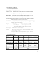
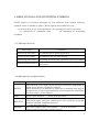
3194M01
CUXⅡ SERIES
ELECTRONIC COUNTING SCALE
OPERATION MANUAL
H I J K
Shinko Denshi Co., Ltd.
01-12-1998 NS
INDEX
1. SPECIFICATIONS. . . . . . . . . . . . . . . . . . . . . . . . . . . . . . . . . . . . . . . . . . . . . . . . . . . . . . . . . . . . . . . . . . . . . . . . . . . . . . . . . . . . 3
1-1. GENERAL SPECIFICATIONS..........................................................................................6
1-2. STANDARD MODELS ...................................................................................................6
2. UNPACKING & INSTALLATION . . . . . . . . . . . . . . . . . . . . . . . . . . . . . . . . . . . . . . . . . . . . . . . . . . . . . . . . . . . . . . . . . . 7
2-1. UNPACKING...............................................................................................................7
2-2. INSTALLING THE WEIGHING PAN.................................................................................7
2-3 TO LEVEL THE SCALE ..................................................................................................7
2-4 PERFORMANCE TEST...................................................................................................8
3. OPERATION KEY FUNCTIONS. . . . . . . . . . . . . . . . . . . . . . . . . . . . . . . . . . . . . . . . . . . . . . . . . . . . . . . . . . . . . . . . . . . 9
4. BEEP SIGNALS AND CONDITION SYMBOLS. . . . . . . . . . . . . . . . . . . . . . . . . . . . . . . . . . . . . . . . . . . . . . . 10
4-1 MESSAGES BY BEEP................................................................................................... 10
4-2 MESSAGES BY SYMBOLIC LETTERS.............................................................................. 10
5. OPERATION . . . . . . . . . . . . . . . . . . . . . . . . . . . . . . . . . . . . . . . . . . . . . . . . . . . . . . . . . . . . . . . . . . . . . . . . . . . . . . . . . . . . . . . . . . 11
5-1. TARE ....................................................................................................................... 12
5-2. UNIT WEIGHT SET (SAMPLING) .................................................................................. 13
1.) QUANTITY SET SAMPLING ................................................................................... 13
2.) DIRECT ENTERING OF UNIT WEIGHT..................................................................... 14
3.) SCS (AUTOMATIC RE-SAMPLING SYSTEM) ............................................................ 15
5-3. RE-SAMPLING .......................................................................................................... 16
5-4. COUNTING............................................................................................................... 16
1.) NORMAL COUNTING ........................................................................................... 16
2.) ACCUMULATE COUNTING .................................................................................... 16
3.) FIXED UNIT WEIGHT METHOD.............................................................................. 17
5-5. MEMORY LOOK -UP.................................................................................................... 17
5-6. MEMORY STORE ....................................................................................................... 17
5-7. MEMORY DATA CALL UP IN WORKING AREA ................................................................. 19
5-8. LIMIT SET AND COMPARING....................................................................................... 19
5-9. FUNCTION SET......................................................................................................... 21
A.) FUNCTION SET .................................................................................................. 21
B.) FUNCTION TABLES ............................................................................................. 22
C.) CONTENTS OF INTERFACE .................................................................................. 23
6. CALIBRATION . . . . . . . . . . . . . . . . . . . . . . . . . . . . . . . . . . . . . . . . . . . . . . . . . . . . . . . . . . . . . . . . . . . . . . . . . . . . . . . . . . . . . . 24
7. TROUBLE SHOOTINGS. . . . . . . . . . . . . . . . . . . . . . . . . . . . . . . . . . . . . . . . . . . . . . . . . . . . . . . . . . . . . . . . . . . . . . . . . . . 26
1. SPECIFICATIONS
1-1. General Specifications
Measuring System : Tuning-fork system.
Sampling System : Semi-automatic counting and storing system(SCS sampling)
Storing by known sample quantity entered via ten -key
Storing by known Unit Weight entered via ten -key
Memory Bank
: Memorable various Unit Weight and Tare Weight up to 300
units. ( ID 1 to 30 Unit Weight with TARE W.)
Accumulation function : Accumulate to measured count data, and adds an optional
number(quantity) inputted by the ten -key.
Limit Function
: Judges if the object has quantity in a specific range by setting by
setting upper/ lower limits.
Display
: Quantity
; VFD 7 digits/12.5 mm H
Total Weight
; LCD 7 digits/12.5 mm H
Average Piece Weight ; LCD 7 digits/12.5 mm H
Power Supply
: 9VDC/400mA with AC Adapter
Options
: Output for Shinko printers. / Bidirectional RS232C output.
Relay contact output.
Rechargeable Battery option (Operable for approx. 5 hours).
1-2. Standard Models
MODEL
CUXII-600
CUXII-1500
CUXII-3000
CUXII-6000
CUXII-12K
CAPACITY
600g
1500g
3000g
6000g
12000g
READABILTY
0.01g
0.05g
0.05g
0.1g
1g
0.002g
0.01g
0.01g
0.02g
0.1g
10 mg
25 mg
50 mg
100 mg
200 mg
1 mg
2.5 mg
5 mg
10 mg
20 mg
1 mg
2.5 mg
5 mg
10 mg
20 mg
HIGH RES’TION
READABILITY
MINIMUM UNIT
WEIGHT FOR SCS
RESOLUTION
IN COUNTING
COUNTABLE
UNIT WEIGHT
PAN SIZE
140mm dia
234 x 204 mm
WEIGHT
3.2 kg
3.9 kg
1
2. UNPACKING & INSTALLATION
2-1. Unpacking
Unpack the container carefully. Examine the packaging and the device for any
damage, and report it to the shipper if there is any. Try to keep the scale
upright.
Check for enclosures as follows:
① Scale main uni
t
② Weighing pan with pan base
③ AC Adapter
④ Operation manual
Note : 1. If any items are missing or any damage is discovered immediately notify
your place of purchase or a dealer.
2. Keep box and shock absorber pad after installation. They are required for
transportation.
2-2. Installing the Weighing Pan
Place the pan base packed with the weighing pan on the scale. Fix it by driving
the nut on the pan base to the screw in the center of the scale. Place the
weighing
pan properly on the pan base.
* The receiving element of the pan base is directly linked with the delicate weighing
mechanism. A tension or a side force may damage the unit.
2-3 To Level the Scale
The scale must be level for proper operation. Use the 4 level adjusters located at
the 4 corners of the scale main unit to adjust the horizontal position of the scale
until the bubble of the bubble level lies within the red circle. Ensure that the
scale sits solidly and does not wobble due to uneven adjustment.
2
2-4 Performance Test
1. Connect the AC adapter at the rear of the scale, then plug the cord in line
outlet.
2. Press the ON/OFF key. All display, segments and characters will blink for
about 4 seconds as a self test.
3. Verify that the display changes by touching the pan slightly, and that it
returns immediately to the original by releasing it.
** INSTALLATION PRECAUTIONS
The CXI
Iis a precision instrument and requires careful handling. Try to select a good,
clean environment for installing the scale.The following factors may cause the scale to
return inaccurate measurements.
1. Installation on a soft surface that may flex when objects are put on it or put on the
scale.
2. Environments that have greatly varying temperature and humidity.
3. Environments subject to vibration or an unstable surface for installation of thescale.
4. Environments subject to air flow from heaters or other air conditioning units.
5. Environments subject to corrosive gases or large amounts of dust.
6. Environments subject to direct sunlight.
3
3. OPERATION KEY FUNCTIONS
ON/OFF
: ON/OFF key for the balance.
RE
: Improv ing unit weight by increasing samples.
SCS
: Used to command automatic calculation and storage of
average unit weight of sample materials in the unit.
T
R.M.
: Tare and parameter change
: Used to recall memorized Unit weight (and Tare) from memory-bank,
inputting code number by the ten -key.
No.
: Used to set code numbers for various Unit weight (and Tare)
banking, and memory look up for Unit weight (and Tare).
TARE PRESET : Taring a known tare weight inputting by the ten-keys.
When needing to confirm tare weight, look up current tare value shown
on display for about 2 seconds after press TARE
PRESET.
UNT.W. SET : Used to unit weight setting.
Storing of a known unit weight inputting by the ten -keys.
LMT
: Used to limit function( comparator ) setting.
Storing of limit value for setting points.
MODE
: Function/mode change. Function modes such as bar graph indication,
A u t o -Zero, Auto-Power off, stable judgment, resolution select,
I n t e r f a c e , u n i t s e l e c t i o n and the calibration mode could be called by
Pressing the
ADD
MODE key.
: A key performs like an adding key of a calculating function, adds a
counted result to the total.
SMPL SET : Used to sample quantity setting.
Sampling by inputting known sample quantity from the ten -key.
0 t o 9 key : Ten numeric keys, called commonly as ten-keys.
. key
: Decimal point key, effective only in the setting of the unit weight and
the tare preset.
C/AC
: Used to clear the numbers inputted by the ten -key, unit weight data
and tare preset data clear.
4
4. BEEP SIGNALS AND CONDITION SYMBOLS
CUXI
Isignals you various messages by four different beep signals and four
symbolic letter as shown as under. These signals and symbol tell you;
(a) instruction to the next operation, (b) warning for faulty operation,
( c ) indication of unsuitable data,
(d) indication of measuring
condition.
4-1 Messages by beep
Beep Signal
Conditions
Short beep (one time)
: Confirmation for pressing the key.
Long beep (one time)
: Completion for set data storing.
Short beep (two times)
: Warning for faulty key operation. (Try to re-input)
Short beep (three times)
:
Warning for miss key operation. (Stop the
operation)
4-2 Messages by symbolic letters
Symbol
LIGHT
ADD
NON UNI
EXCESS
Conditions
The UNIT W. is too light for the balance resolution. Impossible to
count, use a balance of smaller capacity.
While flickering, it is possible to count, but a counting error may be
produced due to the rough uniformity of the samples or depending
on the accuracy of the balance.
Please add samples. -- while SCS operation -The samples are not uniformed or contain some irregular material.
Unload samples until the symbol goes off or pick the irregular
material off from sampling material.
-- while SCS operation -Too many samples have been added. -- in SCS operation –
Unload samples until the symbol goes off.
5
5. OPERATION
Basic operation is divided into the four procedures
(A) Tare if necessary
(B) Unit weight set ( sampling)
(C) Re-Sampling if necessary
(D) Counting ( loading all the samples )
Procedure (A) has 2 ways
Procedure (B) has 4 ways
Besides normal counting method, we have 2 different methods
Other operations include
(E) Memory look-up
(F) Memory store
(G) Memory call-up
(H) Limit set and comparing
( I ) Function set
6
5-1. Tare
1.) Tare with actual tare load
Load tare.
P r e s s T key.
2.) Tare with numerical keys.
Enter tare weight with numerical keys.
P r e s s TARE PRESET key.
# You must pre-load the tare before sampling.
< Set data clear >
Press
C/AC key until the display goes “ 0 “.
< Look up tare >
Press
TARE PRESET key.
Current tare value shown on display for about 2 sec.
7
5-2. Unit weight set (sampling)
1.) Quantity set sampling
Tare the balance by pressing T key.
Display : Exactly 0 .
Load samples precisely counted in advance.
Enter quantity* of the samples with the numerical keys.
Press SMPL SET key.
( * you cannot get accurate counting without correct quantity set.)
Features
- Since it is difficult to count many samples by manuals , we can usually load
few pieces.
- Re-sampling is strongly recommended.
- Sampling error can occur depending on how re-sampling is made. (depends
on operators )
< Set data clear >
Press
8
C/AC until the display goes “ 0 “.
2.) Direct entering of unit weight
Enter unit weight with numerical keys.
Press UNT.W. SET key.
Features
- Good when average weight is almost precisely known.
- Bad when unit weight set differs a lot from samples’ average.
- Re-Sampling is recommended.
- Sampling error can occur depending on how re-sampling is made. (depends
on operators )
< Set data clear >
P r e s s C/AC until the display goes “ 0 “.
9
3.) SCS (Automatic re-sampling system)
1. Press SCS key.
Beep then flicker :
on 5 * (on QUANTITY display)
(*Initial quantity can be changed by ten -key)
Appear
:
ADD
(on WEIGHT display)
2. Load exactly five(5) samples.
Flicker to the RED LED in the SCS key and
PuSh
on WEIGHT display
3. Press SCS key.
4. Add an optional quantity but within number of acceptable addition
q u a n tity (display on the UNIT W. position).
Adding samples are no needs count.( because acceptable number decrease at
adding.) If too many samples added, sampling cannot be proceeded. Scale tells
you by the sign
Sub. Meaning subtract quantity.
Wait to stable after beep then flicker :A DD (on WEIGHT display)
Also change to the acceptable addition quantity.
5. Continue the previous operation until the scale automatically completes
sampling.
H o w e v e r , even before the conditioning, the reference unit weight may be fixed
on by pressing the
SCS key at an optional time when the fixation is required.
(In this case, sampling accuracy is not guaranteed.)
Features
- Operators can just concentrate on counting a few pieces.
- Just following the instruction brings accurate sampling.
- Re-sampling is not necessary in most cases.
- No sampling error. (not depend on operators)
- Scale rejects samples in failure of unit weight set.
10
5-3. Re-Sampling
1. After unit weight is set, load or add (other) samples.*
*too many sampling will cause sampling error.
To avoid an error, bar graph is very useful.
2. Press RE key.
5-4. Counting
1.) Normal counting
Load all the ( remaining ) samples by degrees seeing bar graph.
*if the bar graph goes beyond max/min limits, Re-Sampling should be made
again.
2 .) Accumulate counting
1. Unit weight has been set.
2. Load partial samples.
3. Press ADD key.
4. Remove samples.
5 . Load other samples in the same way.
6. Press ADD key.
7. Remove samples.
8. If you press MODE key, quantity on the display changes from quantity
for the loaded samples to the accumulated quantity and vice verse.
11
3.) Fixed unit weight method
# Enable the bar graph when using this counting method
1. Unit weight has been set.
2. Load or add (more) samples in a way the bar graph does not go beyond
min/max limits. In other words, limit the samples’ quantity in this
condition.
3. Press RE key.
4. Repeat the same procedure until you can complete counting.
5-5. Memory look-up
1. Enter ID number with numerical keys
2. Press No. key.
5-6. Memory Store
#Memory store with currently set weight
Call up an ID to save data using Memory look-up.
Unit weight set
1. Enter unit weight with numerical keys.*
2. Press UNT.W. SET key.
*If you fail to enter weight and press numerical keys, the current unit
weight in the working area will be stored.
12
Tare set
1. Enter tare weight with numerical keys. *
2. Press TARE PRESET key.
*If you fail to enter weight and press numerical keys, the curren t tare
weight in the working area will be stored.
[To clear data in MEMORY BANK]
1. Call up an ID to clear data from memory using memory look-up.
2. Press and hold down the C/AC key until the UNIT W. displays goes blank.
The ID memory data (both UNIT W. and TARE) are cleared.
Memory store with currently set weight
Unit weight and/or tare weight are set in the working area.
1. Call up an ID to save data using memory look-up.
2. Press UNT.W. SET key.
Unit weight is saved in the ID.
3. Press TARE PRESET key.
Tare weight is saved in the ID.
4. Return to the working area, press RE key.
13
5-7. Memory data call up in working area
1. Enter ID number with numerical keys.
2. Press
No. key. (Memory data look-up.)
3. Press R. M. key. (The data set in the ID is called up to the working area.)
[To clear the working area data]
To clear data settings (both Unit W. and Tare),
press and hold down the C/AC key until the displays goes blank.
5-8. Limit set and Comparing
[Limit Set]
Limit function must be set enable ( see function table and set).
You can set either one point or two points limit.
Press LMT key.
Li-LO appears at Weighing display, and low limit value shows
that currently set at UNIT.W display.
Enter low limit value with numerical keys.
Press LMT key.
Low limit set, and a beep will sound to sign. Then Li-HI
appears at Weighing display, and high limit value shows that
currently set at UNIT.W display, then advance to the high
limit setting.
Enter high limit value with numerical keys.
Press LMT key.
High limit set, and a beep will sound to sign. High limit set,
and go back to working area.
14
[Look up limit values]
Press LMT key.
Li-LO appears at Weighing display, and low limit value shows
that currently set at UNIT. W display.
Press LMT key.
Li-HI appears at Weighing display, and high limit value
shows that currently set at UNIT.W display.
Press LMT key.
Go back to working area.
In case that only one point(13.Pn.
1 ) is selected to set, low limit value shows after
press LMT key at once go back to working area.
[Comparing ( how limit function work )]
Suppose two limits have been set;
When the quantity is under the low value, it is ranked as “ LO “
When the quantity is between the low value and the high, it is ranked as “ OK “
When the quantity is over the high value, it is ranked as “ HI “
Notes
# Such settings as lower limit value >= Higher limit value will be error.
# Comparative judgment condition;
At one point (13.Pn.
1) :
L O : v a l u e < lower limit.
At two point( 13.Pn.
OK: lower limit =< value.
2) :
LO: value < lower limit
OK: lower limit =< value =< higher limit
HI : higher limit< value
# We get beep sound in response to comparing result.
The condition is selectable by function set.
15
5-9. Function set
A.) Function set
1.) Press MODE key until QUATITY display shows “ Func “ .
2.) The display then changes to “ 1. A.0
1“
To change setting parameter, press T key
3.) To forward the next title, press MODE key.
To exit function setting mode and enter the working area, press any key
without pressing the MODE, T keys to return to the working area.
16
B.) Function tables
1. SEL. limit function
* 1: disable
11.Co. enable when
12.Li. enable where
* 1: anytime
13.Pn. limit setting point(s)
14.bu. buzzer enable where
2.S.S. SCS mode selection
2: enable
2: in stable state
0: except zero point or below(minus value).
* 1: any area.
1: o n e
*2: two
* 0: disable in any area
1: L O
2: O K
3: HI
4: LO+OK 5:OK+HI 6:LO+HI
* 1: normal SCS mode
2: high grade SCS mode (precise sampling)
3.b.G. bar graph indication
0: disable
* 1: count gap (fraction)
2: reminding for capacity
4.A.0
0: not effective
* 1: automatically adjusts to zero point
5.A.P.
Auto Zero
Auto power off
(effective with battery option)
6.S.d. stable judgement
0: not effective
* 1: automatically turns off of power
1: rough …(* 2)…4 : precise
7.d.i. weighing display resolution select
* 1: normal mode
2: high resolution mode
8.IF.
Interface
0: output is not effective
1: constant serial output (6-digit format)
* 2: constant serial output (7-digit format)
3: RK type output format
A.un.
unit selection
* 0: g
1: o z
2: lb
* mark shows the status set at the shipping time.
#other functions are not mentioned here because they are not related to operations.
17
C.) Contents of Interface
FUNCTIONS
Output Contents
Output Control
Baud Rate
Parity Bit
DISPLAY
CONTENTS
81.dA.
1
Counting quantity data output
81.dA.
81.dA.
2
3
Weighing data output
81.dA.
4
Count, Weight, APW data output
81.dA.
82.o.c.
5
0
Count, Weight, Tare weight data output
82.o.c.
1
Constant serial output
82.o.c.
2
Constant serial output when stabilized.
* 82.o.c.
3
Output by pressing PRINT key.
82.o.c.
4
Automatic output with a load.
82.o.c.
5
82.o.c.
6
82.o.c.
7
One output by pressing * key but after
stabilized.
* 83.b.L.
1
1200 bps.
83.b.L.
2
2400 bps.
83.b.L.
3
4800 bps.
A.
0
No parity bit
84.P A.
1
Odd parity check
84.P A.
2
Even parity check
* 84.P
Average Piece Weight data output
No output
One output when stabilized.
- No output with unstable data.
One output when stabilized.
- Constant output with unstable data.
* mark shows the status set at the shipping time.
18
6. CALIBRATION
We recommend you to calibrate the balance with a reference weight of full
capacity of the scale according to the following procedure, just before the
operation whe n it is installed, transported, or after certain time passed from the
previous calibration.
Particularly it is necessary when the working district of the scale is changed,
since the measuring data changes proportionally to the change of G of gravity
which changes according to the latitude.
The following calibration procedure is simple, and not subject to operator errors,
but does require a reference weight of the full capacity of the scale.
(1) Press the
MODE key and keep until Func appears for roughly 5 to 6 sec., and still
continue pressing until
(2) Press the
CAL appears.
T key, with it still held down, just hit the MODE key, and release both keys
together.
(3) The display will indicate
by pressing the
unit X . Select weight unit from parameters “0” to “2”,
T key. The contents of the parameters are the same as at function
A. un. X. See page17. After setting the parameter, press the MODE key.
(4) The display will indicate
on 0. Verify that no load is placed on the scale, as the
zero adjustment is automatically achieved.
(5) Allow to appear
on FS. Apply the reference weight of the full capacity of the
scale just in the center of the weighing pan. The span adjustment will
automatically be achieved. Use a weight of the unit selected in above (3).
(6) When the calibration is completed, the display will automatically return to the
measurement mode.
19
NOTES
1. To stop the calibration operation, press any key (Ex.
pressing the
2.
RE, C/AC, T key) without
MODE key to return to the working area.
O-Err signs that the reference weight is over the full capacity.
3. The calibration is available with a reference weight of over 50% of the scale
capacity. Nevertheless, we recommend to adjusting by a full capacity weight.
1-Err will appear if the load is less than 50% of the capacity.
4.
2-Err
will appear if the error exceeds 1% of the capacity, or any other object than
a reference weight. Or, perhaps the scale is defective.
BATTERY OPTION (Nicd battery pack)
Charge hours
: Approx. 12 hours ( at 120VAC use) to 15 hours (at 230VAC use)
u n d e r p o w e r s w i t c h of the scale “OFF”.
Operation hours : Approx. 5 hours continuous operation without output.
A u t o -Sleep
Low Battery
: Sleeps 3 minutes after last operation, for power saving.
: L O W -BATT symbol appears on when the voltage falls under
the specification.
20
7. TROUBLE SHOOTINGS
SYMPTOMS
No display appears
Display is unstable
Displayed value is not
correct.
Wrong linearity.
Unavailable weigh up to
the capacity.
o-Err appears.
u-Err appears.
b-Err appears.
CAUSES & REMEDY
* AC adapter is not connected, or the ON/OFF key is OFF.
- Connect the AC adapter.
* Battery has been consumed (with battery option).
- Charge the battery.
* Affected by a wind or oscillation.
- Check the location and the response speed.
* The installation base is unstable.
- Check the base.
* Weighing pan or tare touches something.
- Check around.
* Tare is not reduced.(Wrong taring operation) .
* Unit is not level.
* Span has changed by effect of G gravity due to the
relocation in a distance.
- Calibrate the scale.
* Sensitivity of electronic circuit has changed due to the
transportation or the time lapse.
- Calibrate the scale.
* Weighing pan is contacting the dust cover or the like.
* Weighing objects are contacting with the wind-shield.
* Power voltage is not enough for the unit.
* Weighing objects are non-uniform.
* Weighing objects included foreign matters or some
irregular material.
* Sampling operation is some fault.
* Weighing mechanism is something wrong.
* Characteristics have changed, or mechanism adjustment
has changed by some reason.
- Contact our service representative.
* Gross load weight exceeds the scale capacity.
Weighing range = Full weighing range − Tare value.
* Weighing range has changed by some damage on the
weighing mechanism.
- Contact our service representative.
* Something contacts the weighing pan to lift it.
* The balance of mechanism has changed by some reason.
- Contact our service representative.
* Electronic error, by a static electricity or a noise.
- Contact our service representative.
21