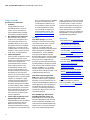
1
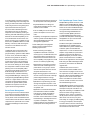
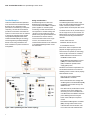
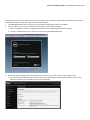
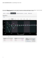
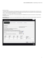
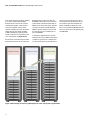
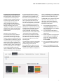
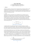
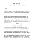
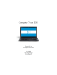
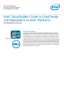
Intel® Cloud Builders Guide
Intel® Xeon® Processor-based Servers
Dell* OpenManage* Power Center
Intel® Cloud Builders Guide to Cloud Design
and Deployment on Intel® Platforms
Dell* OpenManage* Power Center
AUDIENCE AND PURPOSE
Intel® Xeon® Processor E5 Family
This reference architecture outlines the usage of energy management and thermal
technologies as part of planning, provisioning, and optimizing strategies in enterprise
and cloud data centers to reduce energy cost and address constrained power situations.
It is intended for data center administrators and enterprise IT professionals who seek
energy management solutions to achieve better energy efficiency and power capacity
utilization within existing or new data centers. The actions and results as prescribed can
be used as a reference to understand energy management solutions implemented with
the use of hardware and software components. The reader should be able to develop
appropriate energy management solutions based on the design options presented using
Dell* OpenManage* Power Center and Dell PowerEdge* R-series servers implementing
Intel® Power Management technologies.
Intel® Cloud Builders Guide: Dell* OpenManage* Power Center
Table of Contents
Executive Summary......................................................................................................................................................................................................................................................... 4
Introduction........................................................................................................................................................................................................................................................................... 4
Server Power Management......................................................................................................................................................................................................................................... 5
Dell OpenManage* Power Center............................................................................................................................................................................................................................. 5
Dell PowerEdge* Servers.............................................................................................................................................................................................................................................. 6
Dell PowerEdge R620................................................................................................................................................................................................................................................ 6
Dell PowerEdge M620............................................................................................................................................................................................................................................... 6
Dell PowerEdge R720................................................................................................................................................................................................................................................ 6
Dell PowerEdge M1000e Blade Enclosure..................................................................................................................................................................................................... 6
Intel® Node Manager................................................................................................................................................................................................................................................... 6
Test-Bed Blueprint............................................................................................................................................................................................................................................................ 8
Design Considerations............................................................................................................................................................................................................................................... 8
Software Architecture.............................................................................................................................................................................................................................................. 8
Hardware & Software Description..................................................................................................................................................................................................................... 9
Physical Architecture................................................................................................................................................................................................................................................. 10
Server Setup & Configuration............................................................................................................................................................................................................................... 11
Adding the Enterprise License Key to the iDRAC7............................................................................................................................................................................. 11
Dell OpenManage Power Center Installation & Configuration.......................................................................................................................................................... 12
Global Configuration................................................................................................................................................................................................................................................... 14
Find Devices..................................................................................................................................................................................................................................................................... 14
Visualizing Devices in Power Center............................................................................................................................................................................................................ 17
Creating and Managing Groups....................................................................................................................................................................................................................... 18
Energy Management Use Cases................................................................................................................................................................................................................................ 22
Use Case One: Monitoring Power, Temperature, and Events of a Device or Group.............................................................................................................. 22
Use Case Two: Creating Power Policies to Increase Server Density............................................................................................................................................. 28
Use Case Three: Surviving Power and Thermal Demands in the Data Center........................................................................................................................ 35
Things to Consider............................................................................................................................................................................................................................................................ 38
Architectural Considerations................................................................................................................................................................................................................................. 38
Scalability..................................................................................................................................................................................................................................................................... 38
Power Management............................................................................................................................................................................................................................................... 38
Power Capping Capability in Dell OpenManage Power Center.................................................................................................................................................... 38
Glossary................................................................................................................................................................................................................................................................................... 38
Intel Node Manager..................................................................................................................................................................................................................................................... 38
Intel® Data Center Manager (Intel® DCM)........................................................................................................................................................................................................ 38
2
Intel® Cloud Builders Guide: Dell* OpenManage* Power Center
Dell OpenManage Power Center.......................................................................................................................................................................................................................... 38
References............................................................................................................................................................................................................................................................................. 38
3
Intel® Cloud Builders Guide: Dell* OpenManage* Power Center
Executive Summary
The evolution of cloud computing has
resulted in highly efficient and carefully
optimized data centers with increased
server density and capacity that makes
considerations on energy consumption
and utilization extremely critical along
with several other factors that were
not as significant in smaller data centers
of the past. To support this evolution,
Intel works with end users to create
an open data center roadmap of usage
models that address key IT pain points
for more secure, efficient, and simple
cloud architectures built on a foundation
of transparency. This paper describes
an Energy Management reference
architecture based on Dell and Intel
solutions with usage models aimed at
data center power efficiency and optimal
utilization of provisioned power and
cooling capacity.
The goal of energy management usage
models is to optimize productivity per
watt in order to reduce total cost of
ownership (TCO). Requirements include
the capability to monitor and cap power
in real-time at server, rack, zone, and data
center levels. This means the ability to
monitor and manage aggregated power
consumption within a rack, zone, or data
center based on available power and
cooling resources.
Intel® Node Manager was implemented on
Intel® server chipsets starting with Intel®
Xeon® processor 5500 series platforms.
After significant improvements, Intel®
Node Manager 2.0 was introduced in 2012
on server platforms supporting the Intel®
Xeon® processor E5 family (presented in
this document).
In this reference architecture we used
Dell* PowerEdge* R-Series Servers with
Intel Node Manager and Dell OpenManage*
Power Center which uses Intel® Data
Center Manager (Intel® DCM) to provide
data center energy efficiency through
4
real time power monitoring of the servers,
power capping, and policy based energy
management.
We describe the following energy
management use cases in detail along
with experimental results and data:
1. Real-time Server Energy Usage
Monitoring, Reporting, and Analysis
to get continuous and actual
energy usage visibility via agentless
monitoring of the servers along with
other devices and systems in the
enterprise network, data center, and
facilities. The actionable reporting
and analysis with real-time power
monitoring enables reduction in
energy cost and carbon emissions.
2. Power Guard Rail and Optimization
of Rack Density by imposing power
guard to prevent server power
consumption from straying beyond a
preset limit. The deterministic power
limit and server power consumption
ceiling helps maximize server count
per rack and therefore return of
investment of capital expenditure per
available rack power when the rack is
under power budget with negligible
or no per server performance impact.
3. Disaster Recovery/Business
Continuity by applying significantly
lower power caps to reduce power
consumption and heat generation
when unforeseen circumstances
like power outage and cooling
system failure occurs. In these
scenarios, it may be appropriate
to set aggressively lower power
caps, though performance would be
affected. The use case illustrates
how this works at a data center
location or a group of servers.
4. Power Optimized Workloads to
achieve power efficiency. Workload
profiles are built and a maximum
performance loss target set.
Experiments determine how much
capping can be applied before
the performance target is hit.
The approach is to match actual
performance against service level
requirements. For workloads that
were not processor intensive, we
were able to optimize server power
consumption by approximately
20 percent without an impact on
performance. For workloads that
were processor intensive, for the
same 20 percent power saving,
we saw an 18 percent decrease in
performance. For a 10 percent power
reduction, performance decreased by
14 percent.
5. Data Center Energy Reduction
through Power Aware Support for
Multiple Service Classes showcases
the ability to enforce multiple SLAs
across different populations of users
with different priority workloads.
Workloads that ran over a period of
eight hours realized 25 percent less
energy consumption.
The paradigm of cloud computing brings
opportunity for data center efficiency.
Energy management usage models
addressed here can substantially help to
meet power management requirements.
Introduction
Enterprise data center efficiency has
become a central focal point for many
industry leaders and all facets of the data
center are being scrutinized for efficiency
modeling. Components across the data
center infrastructure are becoming
more power efficient and offering data
collection points to give administrators
more control of their enterprise
environments. Power and Thermal data
collection of an aggregated group of
servers can give data center managers
the ability to use this aggregated
information to formulate new methods to
optimize power usage in the data center
while ensuring power levels are met on
Intel® Cloud Builders Guide: Dell* OpenManage* Power Center
a real-time basis. Enterprise computing
is very demanding and is increasing rack
density to new levels. Power and thermal
monitoring and control are gaining more
importance with each new system
that is focused on delivering the best
performance per watt per workload.
Companies are consistently focusing on
lowering TCO while still meeting customer
demands for increased capability to run
more workloads in the data center. The
benefit of tuning your workloads to your
data center capabilities allows for a solid
delivery of services, while ensuring the
infrastructure is utilized in the most
efficient manner.
•Increased total operational costs due to
increased power and cooling demands
•Physical limitations of cooling and
power within individual servers, racks,
and data center facilities
•Lack of visibility into actual real-time
power consumption of servers and
racks
•Complexity of management components
and sub-systems from multiple vendors
with incompatible interfaces and
management applications.
These challenges in managing data
centers can be translated into the
following requirements:
Traditionally, data centers were using
nameplate values for their servers to
gauge how many systems could fit within
a rack or circuit, but with the ability to
poll data from systems in real time, a
data center manager can monitor the
actual usage and set a de-rated power
limit on those systems which can allow
for more server density per circuit. Using
de-rated power numbers for data center
planning versus the nameplate power
can increase rack density by 40 percent.
Dell PowerEdge R-series servers are
instrumented for real time monitoring
using Intel Node Manager, and they are
managed using Dell OpenManage Power
Center on a regular basis to ensure the
rack power is kept within boundaries,
and alerts the system admin if power
abatement is required to sustain the
system service level agreements.
•Power monitoring and capping
capabilities at all levels of the data
center (system, rack identification, and
data center). What can be done at an
individual server level becomes much
more compelling once physical or virtual
servers are scaled up significantly.
Server Power Management
•Application of standards-based power
instrumentation solutions available
in all servers to allow management
for optimal data center efficiency.
Extension of instrumentation to enable
load balancing or load migration based
on power consumption, and close
coupled cooling for the management of
pooled power and cooling resources.
Even though servers have become much
more efficient, packaging densities and
power have increased much faster. As a
result, power and its associated thermal
characteristics have become the dominant
components of operational costs. Power
and thermal challenges in data centers
include:
•Aggregation of the power consumed
at the rack level and management of
power within a rack group to ensure
that the total power does not exceed
the power allocated to a rack.
•Higher level aggregation and control at
the row or data center level to manage
power budget within the average
power and cooling resources available.
•Optimization of productivity per watt
through management of power at the
server, rack, row, and data center levels
to optimize TCO.
Dell* OpenManage* Power Center
Dell OpenManage Power Center is a new
addition to the Dell OpenManage family
which connects to Dell PowerEdge R/T/MSeries servers with Intel Node Manager.
The system admin authenticates access
through the Integrated Dell Remote
Access Controller (iDRAC) Version 6
or 7. Dell OpenManage Power Center
provides real-time power monitoring and
management for up to two thousand
servers in a data center.
Included in the higher end model Dell
PowerEdge server is iDRAC Express,
which allows the systems administrator
to monitor power and thermal inlet
temperature. In order to address more
complex usage models, it’s preferred to
upgrade to the Enterprise license for
iDRAC which gives you control of those
power and thermal events. The iDRAC
license can be upgraded to the Enterprise
level during the Dell PowerEdge R-series
purchase or purchased as an additional
upgrade later.
Communication to the servers is
performed via TCP/IP and IPMI and no
other software or plugins on the server
are required for access. iDRAC must have
IPMI over LAN access with Administrator
rights in one of the first three cipher
suites. This allows out-of-band access
from the console to monitor and control
each Dell PowerEdge server.
Dell OpenManage Power Center has been
developed to address several imperatives
that impact enterprise customers on a
daily basis. According to an ENERGY STAR*
2010 Data Center Energy Efficiency
Initiatives report, there is a projected
30-46 percent increase of power in the
data center over the next five years.
Costs today are roughly $7.4 billion (USD)
in energy consumption, and enterprise
customers want to monitor and manage
the energy at a more granular level within
the confines of their own control.
5
Intel® Cloud Builders Guide: Dell* OpenManage* Power Center
The consequences of not managing power
can be related to, but are not limited to
these examples:
•Rack density suffers from poor server
placement, and no real monitoring is
available.
•Unpredictable power bills due to no
central monitoring capability. The
energy provider supplies a bill, but there
is no breakdown from the overall power.
•Brownout or blackout issues cause
loss of workloads. If power could be
mitigated to reduce load then the work
could be sustained to ride through the
outage.
•Stranded power from over-subscribing
servers in racks to ‘play it safe’ and
ensure power limits aren’t exceeded.
•All of these issues, and more, can be
addressed by installing OpenManage
Power Center along with Dell
PowerEdge systems that utilize Intel
Node Manager Technology.
Dell PowerEdge* Servers
Dell’s latest generation of PowerEdge
servers offer the most advanced Dell
server innovations to give you more
power and the tools to harness it. Dell’s
second generation embedded systems
management deploys, updates, monitors,
and maintains the entire server lifecycle,
through truly agent-free management.
This allows customers to process more
data, support more applications, reduce
infrastructure complexity, and increase
efficiencies without increasing bottom line
costs.
To stay innovative, IT managers must
quickly adapt to the changing demands of
customers or constituents. And making
sure IT infrastructure keeps pace can be
a daunting task. Thankfully, with a broad
selection of new Dell PowerEdge servers
with embedded systems management
available, IT managers can spend more
6
time achieving and less time struggling to
keep up.
•Dell PowerEdge R620: The PowerEdge
R620 is an Intel processor-based
2-socket, 1U rack server well-suited
for server rooms or corporate data
centers and remote sites that require
exceptional virtualization, systems
management, and energy efficiency.
•Dell PowerEdge M620: The
PowerEdge M620 is an Intel processorbased 2-socket, half-height blade server
built for virtualization, mainstream
business applications, and front-end
database workloads.
•Dell PowerEdge R720: The PowerEdge
R720 is a mainstream Intel processorbased 2-socket, 2U rack server great
for server rooms or corporate data
centers and remote sites that require
exceptional virtualization, systems
management, and energy efficiency.
•Dell PowerEdge T620: The Dell
PowerEdge T620 is a feature-rich,
2-socket tower server with up to 24
DIMMs, storage capacity of up to 32
drive bays, and Intel Xeon E5 processing
power.
•Dell PowerEdge M1000e Blade
Enclosure: The PowerEdge M1000e
blade chassis enclosure is the robust
foundation for the PowerEdge M series
blade solution, enabling significant data
center density with an easy to deploy
and manage platform that maximizes
power and cooling efficiency.
Improve operational efficiency
•Manage anywhere, anytime with truly
agent-free server management.
•Reduce maintenance time with autoupdate for replacement parts.
•Control cooling costs with better power
monitoring and control.
•Tailor your network to your applications
with fabric flexibility.
Accomplish more
•Get more throughput with major
I/O (input/output) performance
enhancements.
•Accept no compromise on virtualization
with maximum memory density.
•Get faster compute results with the
most advanced processor technology
using the Intel Xeon processor E5
family.
iDRAC7 with Lifecycle Controller,
Dell’s innovative agent-free system
management tool, provides direct
access to hardware status, inventory,
and configuration even if the operating
system is down or not installed. iDRAC7
allows you to monitor, troubleshoot,
and remediate servers. It also sends
you server alerts with improved error
messaging and removes dependence on
the operating system or agents. You get
increased oversight with fewer resources
and lower cost.
In this document, we will be utilizing the
Dell PowerEdge R720xd server. Dell
offers more platforms to meet your data
center needs – the various server models
can be found at http://www.dell.com/
poweredge.
Intel® Node Manager
Intel Node Manager was a server power
management capability that is embedded
in Dell’s latest generation of PowerEdge
servers. Intel Node Manager is hardware
and firmware based technology that is
used to optimize and manage power and
cooling resources in the data center. This
server power management technology
extends component instrumentation to
the server level and can be used to make
the most of every watt consumed in the
data center.
Using intelligent energy management at
the server level helps IT administrators
squeeze extra value and performance
out of existing rack space while reducing
Intel® Cloud Builders Guide: Dell* OpenManage* Power Center
the total cost of ownership by better
managing power and cooling operational
costs. Administrators can improve
business continuity by dynamically
capping power to avoid overcooling
systems, reducing downtime and allowing
critical operations to continue even during
power or thermal events. They can also
balance resources by dynamically moving
power from one part of the data center to
another, depending on where the need for
power or cooling is greatest.
To maximize the benefits of Intel Node
Manager, a management console is
required to aggregate power data and set
policies for physical and logical groups of
servers. Dell OpenManage Power Center
is the featured console in this document,
and we will detail the resources available
to support Intel Node Manager in scale
deployment. Establishing policies gives the
data center administrator the ability to
setup certain scenarios to manage these
four basic usage models.
Group management is utilized in Dell
Power Center while controlling multiple
servers within the physical (or logical)
groups as we described in the previous
section. Establishing boundaries and limits
ensures that the server group operates
within those safe boundaries.
7
Intel® Cloud Builders Guide: Dell* OpenManage* Power Center
Test-Bed Blueprint
Design Considerations
Software Architecture
Intel has worked with Dell to implement
a test bed that features Dell PowerEdge
R-Series servers, designed for highperformance and efficiency in enterprise
computing. The test bed is intended to
provide an environment to simulate the
aspects of a data center that are relevant
to enterprise computing usage models
using Dell PowerEdge R-Series which
include Intel Node Manager technology
and management by Dell OpenManage
Power Center using Intel DCM as the
base framework for power and thermal
management.
Dell PowerEdge servers with Intel
Node Manager technology require
instrumentation with PMBus* compliant
power supplies for real-time power
monitoring. The inlet thermal sensor is
also required for thermal readings and
reaction to those readings via power
policies set by the system administrator.
Authentication in this document is
used as the basic Power Center Login
account, more advanced account
authentication methods can be reviewed
in the Dell OpenManage Power Center
documentation.
The following illustration shows a high
level overview of Dell OpenManage Power
Center connection points to various
systems within the enterprise data center.
The Power Center Server provides http (or
secure https) access for the customer via
Web browser connectivity. Authentication
can be performed using three different
methods:
•Power Center Account
•Windows* Domain Account
•Local Windows Account
Data center assets are split into both
physical and logical groupings, and as
those assets are queried, the technology
used to acquire asset data is as follows:
•iDRAC w/IPMI 2.0 for Dell servers or
WS-MAN for blade chassis
•Simple Network Management Protocol
(SNMP) for Power Distribution Unit
(PDU) and Uninterruptable Power
Supply (UPS) access
Hardware and software requirements for
the devices listed above must meet the
following criteria in order to work properly
with Dell Power Center.
•The server must comply with Dell
iDRAC6/iDRAC7 standards.
•PDU or UPS devices must comply with
the Management Information Base (MIB)
provided by their vendor through the
SNMP interface.
•The devices must provide Power Center
exclusive access as the policies and
monitoring are to be controlled from a
centralized data consolidation reference
point. Allowing interaction beyond
Power Center will impact expected
results.
Figure 1: Dell* OpenManage* Power Center Topology
8
•The Baseboard Management Controller
(BMC), through which Power Center
communicates with the devices, must
have a local user with administrative
Intel® Cloud Builders Guide: Dell* OpenManage* Power Center
control. The device must be configured
to use at least one of the cipher suites
0-3 and enable “IPMI over LAN” setting.
•The WS-MAN user, through which
Power Center communicates with
the chassis, must be a local user with
administrative control and enable the
“Web Server” service.
Once the requirements have been met
and the assets have been collected into
the Power Center database, the power
and thermal data is collected on a user-set
time basis. This data collection runs 24x7
and is available for any authenticated
user logging into Power Center. There
is monitored, two-way communication
between OpenManage Power Center and
each asset.
Figure 2: Dell* OpenManage* Power Center Asset Data Collection
Hardware & Software Description
Dell* OpenManage*
Power Center
Power Center VM
Server 1
Virtual Machine hosted
4 Virtual CPUs, 4GB RAM, 60GB Hard Disk
on VMware*
Intel® Server Host running Microsoft Windows* 2008 R2 64-bit
VMware ESX5i
Dell OpenManage Power Center (Ver. 1.0)
Dell PowerEdge* R720xd
2-way Intel® Xeon® processor E5-2660 @ 2.2GHz with 64GB RAM, 8 x 300GB
SAS HDD, with Dual 750W PSU
Microsoft Windows 2008 R2 64-bit
Server 2
Dell PowerEdge R720xd
2-way Intel Xeon processor E5-2660 @ 2.2GHz with 64GB RAM, 8 x 300GB SAS
HDD, with Dual 750W PSU
Microsoft Windows 2008 R2 64-bit
9
Intel® Cloud Builders Guide: Dell* OpenManage* Power Center
Physical Architecture
Figure 3 shows the test bed deployment
architecture. Dell OpenManage Power
Center is installed on a virtual machine,
and the local DNS/DHCP and Active
Directory services are provided by the
lab subnet on which the systems reside.
The two physical Dell PowerEdge R720
servers are used for case testing with
Dell OpenManage Power Center. These
systems have Intel Node Manager
technology implemented and management
communications to the platform occurs
over the iDRAC7 data port which has been
upgraded to the iDRAC7 Enterprise license
model. Dell OpenManage Power Center
connects to the systems out-of-band over
the network to monitor and collect host
Figure 3: Physical Layout of the Test Bed Setup
10
information, power and thermal data,
and other important asset information
to differentiate the data in the Dell
OpenManage Power Center database. This
data will be used to monitor and manage
power consumption.
Intel® Cloud Builders Guide: Dell* OpenManage* Power Center
Server Setup & Configuration
Out of the box setup is quite simple,
adding power cords for each PSU and one
Ethernet cable for Network Interface Card
(NIC) 1, and another Ethernet cable for the
iDRAC7 port. In this testing scenario, we
chose to use the same subnet for both the
data and manageability ports. The reader
is expected to have basic knowledge of
the server configuration and operating
system installation.
1. The iDRAC7 will have a pre-populated
name assigned to it, which is related
to the system tag.
a. The naming convention is: idrac<systemtag>.domain.name where
“domain name” is provided via
DHCP in this case.
b. The default username: root and
password: calvin is used for first
time iDRAC7 authentication.
It is recommended that the
reader change the username
and password to meet their
local information security
requirements.
c. By default, this root user has
administrative rights on the
server.
2. Installation of an operating system
on the Dell PowerEdge server can be
performed as recommended by the
reader. In this document, all default
options were used when installing
Windows* 2008 R2 x64 and all of
the latest patches and hotfixes were
applied that are current as of the
date of this publication. Readers
may select a different operating
system that is supported by Dell on
the PowerEdge servers, and any
workload can be used to showcase
the power differences shown.
3. Dell OpenManage Power Center is
able to scan this simple subnet test
bed scenario to authenticate, add,
and monitor the servers by using
the credentials provided in Step
number 1b. If you change the default
username and password, be sure to
update OpenManage Power Center
settings as well.
Adding the Enterprise License Key to
the iDRAC7
This section may be optional depending
on whether or not your Dell PowerEdge
Server was pre-configured with an
Express or Enterprise license. If your
system was ordered as an Express model,
the following steps show you how to
install the Enterprise update (which is
purchased from Dell).
1. As stated above, if your iDRAC
network port is connected to a
network which can assign an IP
address to the iDRAC, you should be
able to connect to the system in your
Internet browser by typing http://
idrac-<systemtag>.domain.com in your
browser’s address field.
a. In our example, http://idrac3m5l6s1.fm.intel.com will open
the Web service on the host and
allow you to login.
b. Use the default username and
password described above.
2. After logging in, you can see the
license model that you have on your
iDRAC at the top of the screen as
shown below. Note that Express
is shown in the top center of the
screen. If you click to Server –
Licenses you can select your iDRAC
Device Option to Import a new
license file.
Note that if you select Learn More – a
browser window will take you to the
Dell Website to instruct you further on
licensing models and how to upgrade to an
Enterprise license if you haven’t already
purchased the upgrade.
11
Intel® Cloud Builders Guide: Dell* OpenManage* Power Center
3. During your license key import (which is matched to your system tag) the iDRAC will setup the license and convert the iDRAC
usage to Enterprise Mode as shown in the below figure.
The iDRAC7 is now setup with an
Enterprise license to monitor and manage
power for the next steps in the Power
Center installation.
Dell* OpenManage* Power Center
Installation & Configuration
This section will document the high
level steps to install and configure the
infrastructure used to exercise the server
power monitoring and management
capabilities supported by Intel on the Dell
PowerEdge R-Series servers specified
above.
Dell OpenManage Power Center is
supported on the following Windows
operating systems:
12
•Microsoft Windows 2003 SP1 Standard/
Enterprise/Small Business Server (x86,
x64)
•Microsoft Windows 2003 R2 Standard/
Enterprise/Small Business Server (x86,
x64)
•Microsoft Windows 2008 Standard/
Enterprise/Small Business Server (x86,
x64)
•Microsoft Windows 2008 R2
•Microsoft Windows 7
•Microsoft Windows Vista (x86, x64)
Dell OpenManage Power Center can be
installed on a standalone server or virtual
machine with the following minimum
configuration:
•A dual-core processor of 2.6GHz
(or higher)
•4GB RAM
•60GB hard disk free space
•Gigabit Ethernet network infrastructure
Web browsers supporting Power Center
include:
•Mozilla Firefox* 5.0 and 6.0
•Microsoft Internet Explorer* 7.0, 8.0,
and 9.0
Intel® Cloud Builders Guide: Dell* OpenManage* Power Center
The following steps assume the reader has a basic understanding of how to install and configure Microsoft Windows Server 2008 R2
x64 Enterprise Edition, and all further steps are based on this installation.
1. Install Dell OpenManage Power Center (version 1.0) and follow the default instructions for installation.
2. After installation, you can connect to the Power Center console via two different methods:
a. Click on the application icon Start – Dell OpenManage Power Center - OpenManage Power Center Console
b. Connect to the Web address in your browser at https://<servername>:8643/powercenter
3. Use the username and password that were used during your setup in Step number 1 above to login to Power Center.
a. You are now presented with the Getting Started screen and we will review the Initial Steps (shown below) to ensure data
collection is optimal for use case testing using the test environment.
13
Intel® Cloud Builders Guide: Dell* OpenManage* Power Center
Global Configuration
On the Initial Steps section, click into the Global Configuration link and verify the following settings:
1. Power Center Monitoring – all devices measuring power and temperature in one minute intervals
2. Default Units – match the local temperature and currency for your region
3. Protocol Type Device Timeout – IPMI and SNMP set to 3 seconds, and WS-MAN set to 60 seconds
4. Energy Consumption – set to your local electricity provider billing rate and the cooling multiplier should be set to 1.5
a. In our example, the billing rate is set to $0.12/kwh (USD)
5. SNMP traps – set to NO
6. Database Policy – leave as default
7. Installation Settings – Database and Kerberos Realm – leave as default
Find Devices
This section will show how to scan for iDRAC6/iDRAC7 controllers to quickly add them into Power Center; this saves time in
deployment and also removes the human error factor in asset control and system data collection. There are some basic steps to add
devices into Power Center:
•Use the discovery page in Power Center to add devices for power monitoring and control
•Configure the search criteria used to scan for the devices that you want to discover
•The end result is a conclusive list of devices found on the Device List page
1. Click on the Find Devices link to open the next level of menus as shown in below.
2. Select the + Add IP Range button, this will open a new window.
3. This new window will allow you to enter in the IP range that you want to scan to find your iDRAC6/iDRAC7 devices. Enter in the
appropriate IP range for your systems and click the Apply button as shown below.
14
Intel® Cloud Builders Guide: Dell* OpenManage* Power Center
4. You can add multiple ranges if you wish, but for this demonstration only one subnet will be scanned as shown below. Be sure to
select the IP range checkbox, and select Next to move to the next step.
5. In the window shown below, you can select the protocol to be used to scan the IP range selected. For this test bed solution we
will use IPMI to communicate with the iDRAC6/iDRAC7. You can add a scanning profile name and a description of the profile for
future use and reference. Be sure to type in the correct iDRAC username and password with administrative access to properly
authenticate to each iDRAC device and click Apply.
15
Intel® Cloud Builders Guide: Dell* OpenManage* Power Center
6. You have now added an IPMI Protocol Scanning Profile to Power Center (as shown below) which can be re-used for future IP
subnet scans on the same, or other subnets.
7. You are now back at the Device Discovery Summary Page, if your data is setup correctly you can click Search to commence your
subnet scan for iDRAC devices.
8. During the scanning process, you will notice the systems that are discovered will be counted on the screen. This process may take
a few minutes depending on the size of your subnet and the number of servers found on the subnet.
16
Intel® Cloud Builders Guide: Dell* OpenManage* Power Center
This shows the details of your recent searches, including the most recent time of scan, how long your scan was running, and the
number of devices discovered. If you add more devices to the subnet, you can rerun the search.
Visualizing Devices in Power Center
Now that you have selectively scanned your subnet for IPMI based devices with the username and password selected, you can go
to the Device List link in Power Center to see the devices that meet your scanning criteria. Note the two Dell PowerEdge R720xd
systems from the test bed shown below.
Dell Power Center is an agent-free application, which means the iDRAC and Host OS are separated. To add more logic to your data
collection, you can remove the IP address and add the Hostname to each system by clicking Edit in the screen shown in the above
figure. This will allow you to pair a hostname with the appropriate iDRAC7 device, without having to know the IP address to ensure
you’re monitoring and controlling the system that is running a particular workload. Simply remove the IP address, and add the
hostname and click Apply as shown below.
17
Intel® Cloud Builders Guide: Dell* OpenManage* Power Center
Creating and Managing Groups
Creating a group of servers gives an opportunity for the data center administrator to put some human logic around the servers
and devices found in the data center. In this test bed, we have two systems which is very simple, but with most enterprise data
centers there are thousands of nodes and devices to manage so physical and logical groups are required to ensure you have a good
understanding of power monitoring and control.
In the main Power Center screen, select Group Management and click Create or Select a Physical Group to create a new data center.
This will be the premise for the sub-groups that we will create to place the devices that we’ve found to meet the usage model
guidelines.
Creating the Data Center
The highest level of Physical grouping is the data center. From here you can create sub groups based around rooms, aisles, racks, and
chassis. To start your physical group creation at the data denter level, follow the steps below.
1. In the next few windows you will select Add New
2. This will pop up a new window to add details for your new data center implementation – add your data center name and
description as they pertain to your scenario.
18
Intel® Cloud Builders Guide: Dell* OpenManage* Power Center
Now you have successfully created the first physical group in Power Center, this is the highest level physical entity to monitor and
manage power and temperature for all other systems below this level.
Creating a Room, Aisle, and Rack inside your Data Center
The next logical step is to break down the physical data center into more logical components, and depending on your data center
layout the configurations here can be as simple or as expansive as you need. For the test bed scenario, we’re going to create a simple
room.
1. Click on to enter new Room Name and Description.
2. Once the Room is created, click on
to enter a new Aisle Name and Description.
3. Now that your room and aisle have been created, click on to enter a new Rack Name and Description.
Be sure to enter the Rack Capacity Units (U) and Total Power Capacity of the Rack in Watts (W) and Apply the changes.
Now you have the basic Data Center Physical Group to add the devices found in the previous section to the rack.
19
Intel® Cloud Builders Guide: Dell* OpenManage* Power Center
Adding Servers to the Rack
In order to add servers to the rack, select the rack from the Physical Group Tab – note that there are no devices listed.
Below the Physical Group Rack tab is a physical layout of the rack.
20
Intel® Cloud Builders Guide: Dell* OpenManage* Power Center
1. Click + Batch Add to add the iDRAC7 devices found previously in our Device Scan.
2. Be sure to Select both devices, you can also determine which slot (U) the systems reside in the rack. For our test bed, we’ll allow
the Auto setting to be selected. Then click Apply.
Now you will notice the servers are put into the rack layout, and depending on rack size, you may have to scroll down to see the
details.
21
Intel® Cloud Builders Guide: Dell* OpenManage* Power Center
Energy Management Use Cases
Use Case One: Monitoring Power,
Temperature, and Events of a Device or
Group
The most basic use case of monitoring
gives us the basis of data to evaluate
the systems in the data center and
make conscious decisions based on that
data. Data center administrators are
expected to have information on rack
density, thermal footprint, and overall
power consumption on a measured basis
across the data center. Dell Power Center
gives simple access to some critical data
found in each and every data center. By
using Intel Node Manger technology in
conjunction with the iDRAC7, the data
center manager can visually see the
power consumed by each server, and the
thermal inlet temperature on the front of
each server chassis. These data points can
be aggregated to make critical decisions
on server placement, manage ways to
optimize cooling, and also maximize the
usage of power circuits throughout the
room.
When devices are added into Power
Center, the data collection process
starts immediately and, in our test bed
demo, measures power and thermal inlet
temperature every minute. Any events
that occur on the systems will show up as
well.
Select the Power Overview Link in the
upper left and tab through to the rack
level shown in the previous section.
Establishing Thresholds
Thresholds are guidelines that administrators can use to establish common boundaries for computing for power and temperature
monitoring. The reader should understand that the power and temperature thresholds that are based on our test data center should
not be used as a guideline, but should develop their own methods to determine the power and temperature thresholds as each data
center is unique and generalizations should not be used.
Click the THRESHOLDS tab to see what settings can be implemented.
22
Intel® Cloud Builders Guide: Dell* OpenManage* Power Center
In our test bed, we will use 6,000W for the critical wattage consumption – this is the limit as derived from our circuit. To calculate the
wattage, we use Ohm’s Law: Watts = Volts x Amps.
Power Threshold Determination
•In the test bed scenario we have 200V x 30A = 6,000 Watts which is our critical threshold.
•The warning threshold is based on exceeding 90 percent utilization of the circuit, and 5,500W is approximately 92 percent
utilization.
Temperate Threshold Determination
•For temperature thresholds, we used a generalization around the test bed data center, the average temperature as measured is
approximately 68F.
•We established a warning threshold of 75F, and a critical threshold of 80F.
•Conversely, if the room is too cool, we have lower limits listed as well at 60F for warning, and 55F as critical.
These thresholds will establish boundaries for the use cases and can visibly be seen in the upcoming displays in this section.
Critical and Warning Events
Select the EVENTS tab and you can see the warnings for the systems inside that rack. Note that for the test bed, we’ve created some
scenarios to generate events for visualization in this document.
23
Intel® Cloud Builders Guide: Dell* OpenManage* Power Center
On the DASHBOARD tab you can see some higher level data points with an easy to read display of average power consumption
(W) and the average inlet temperature for the entire rack. In the screen shot below, you can see the rack level power, and average
temperature as measured by both of the servers in the rack.
Note the power and temperature thresholds shown as described in the previous segment. For power, the test bed is well below the
power consumption thresholds, and the temperature is balanced between the hot and cold thresholds established.
24
Intel® Cloud Builders Guide: Dell* OpenManage* Power Center
Accuracy of the Dell PowerEdge R720 in the Data Center
For accuracy comparison, here are a few pictures of the two Dell PowerEdge R720 servers along with temperature measurements,
using an Ultra U12-41380 Infrared Thermometer and power measurements from the Yokagawa WT-210 Power Meter Application.
25
Intel® Cloud Builders Guide: Dell* OpenManage* Power Center
Power Details
You can drill down further into the
POWER DETAILS tab to visualize the
average power of the rack over time.
In the display you will notice several
power measurements showcased, some
of this data is extracted from Intel Node
Manager statistics which are recorded in
the firmware of the systems.
•Average Power - The average power
value from the previous time point to
the current time point.
26
•Maximum Power – The maximum power
value from the previous time point to
the current time point.
•Minimum Power – The minimum power
value from the previous time point to
the current time point.
•Rack Power Capacity – This is derived
from when you created the rack entity,
in this case 6,000W was the limit of the
rack. As more devices are added to the
rack, this is the hard limit for power in
the rack and should not be exceeded.
The power and temperature thresholds
are also visualized for the entire rack
on the graph. With only two servers in
our circuit, it can be observed that there
is plenty of power available for system
growth in this rack.
Intel® Cloud Builders Guide: Dell* OpenManage* Power Center
Temperature Details
Clicking into the TEMPERATURE DETAILS
tab allows you to trend the inlet thermal
temperature over time. This data is very
helpful in recognizing if there is a cooling
failure in the data center. It can also be
used to determine if you have too much
(or too little) cooling in certain segments
of your data center. This measurement
can help you to balance your cooling
across the room to alleviate over-spending
on cooling.
Similar to the power measurements, there
are Average, Minimum, and Maximum inlet
temperature measurements.
and maximum temperatures shown in
this test bed are balanced between the
thresholds of too hot and too cold. Given
this scenario, the reader could, in practice,
set those tolerances much tighter and
establish a very well defined temperature
setting for the data center.
Note the temperature thresholds
displayed in the graph, the average
27
Intel® Cloud Builders Guide: Dell* OpenManage* Power Center
Use Case Two: Creating Power Policies
to Increase Server Density
As part of the Dell PowerEdge Servers,
Intel Node Manager gives the capability to
set up to 16 discrete policies per server.
These policies can be related to static
or dynamic power limits, temperature
based triggers, and also used to mitigate
potential power outage situations. Intel
Node Manager is a capability built into
a single server and acts on power and
temperature in milliseconds to prevent the
systems from tripping a circuit.
power at a particular power budget, or to
increase server density in a server rack
by managing a group of servers to use
energy for processing, but within data
center circuit power demands.
Power policies can be utilized as a
sustaining activity to maintain rack level
Single Server Policy
To enable a power policy, on the Power Center main screen, select POLICIES.
Select the option; this will pop up a new window as shown below.
You are then directed to the Power Overview window and must select a server or group of servers to place your power policy. In this
instance, we will set a static power policy on the R720-3M system.
28
Intel® Cloud Builders Guide: Dell* OpenManage* Power Center
The screen shows that you can name the policy, and that the power cap can be between 136W and 489W – these numbers are derived
each time the Dell PowerEdge Server reboots and tests the power limits of the platform. These numbers can change if you replace
components, or upgrade memory, hard drives, or other components within the server chassis.
In this scenario, we will set the power cap to be 300W, which is 61 percent of the range that can be consumed by the server. This
power cap is quite low, but is showcased to simulate the power capping technology on the Dell PowerEdge Server using Intel Node
Manager technology.
When you click Next, keep the default settings. Then click Next again, you will see the summary page with the system details.
29
Intel® Cloud Builders Guide: Dell* OpenManage* Power Center
Once you click Apply, this static power cap is installed into the server’s firmware and will remain until you change or remove the policy.
If you check the POWER DETAILS tab for this system, you will notice the workload has settled in at 300W.
30
Intel® Cloud Builders Guide: Dell* OpenManage* Power Center
Multi Server Policy
To establish a multi-server policy, you must simply select a group of systems, whether it is an entire data center, room, aisle, rack, or
chassis. The data provided when selecting any of those higher level groups will contain the information of all the systems beneath it.
There are static and dynamic capping policies for group capping.
Static Policy: The group power cap is a static value manually set for individual servers by the user; this value can only be changed
manually by the user.
Dynamic Policy: The group power cap is dynamically distributed to individual servers based on the power utilization and priority at
each monitoring level.
31
Intel® Cloud Builders Guide: Dell* OpenManage* Power Center
After clicking Next, the Power Allocation screen shows the ability to prioritize different servers to High-Medium-Low if you have
different priorities for the workloads on your systems. In the test-bed scenario, we will keep these systems at Medium (which is
default).
Note how the two systems are operating at different levels, and will both comprise the data that is used to meet the 80 percent limit
on the rack. Keep the default Schedule settings as Always, and click Next to get to the summary page.
32
Intel® Cloud Builders Guide: Dell* OpenManage* Power Center
Once you click Apply, this dynamic power cap is installed into the server’s firmware and will remain until you change or remove the
policy. Check the POWER DETAILS tab for this system, and see how the systems are limited to 80 percent of their maximum power
usage.
33
Intel® Cloud Builders Guide: Dell* OpenManage* Power Center
Let’s review the power scaling in building
a rack full of these Dell PowerEdge
R720xd Servers. Each server has twin
750W Power Supplies, and if we were
using the nameplate value of these
systems to deploy into a rack, we would
simply take the rack power capability
of 6kW and divide by 750W to get the
number of servers we could put into the
rack. That equates to only 8 servers.
We also know from measuring the power
data directly from the server using Intel
Node Manager in conjunction with the
Dell iDRAC7 with Power Center that each
system shows a maximum power limit of
489W. So we do the math again, this time
the same rack power of 6kW divided by
489W to get the number of servers that
we could put into the rack. Now we can
put in 12 servers.
test your own configuration to ensure
the workloads are not impacted. We run
the numbers again, with the 6kW rack
power and divide by 391W per server.
We can now squeeze 15 servers into the
same rack where we could originally only
put 8 servers.
In this power capped scenario, we have
782W per two servers which breaks down
to 391W per system. Just a reminder, this
is a test-bed scenario and you will have to
Figure 4: Rack Density Increase using Nameplate, De-rated, and Dynamic Capped Power
34
Intel® Cloud Builders Guide: Dell* OpenManage* Power Center
Use Case Three: Surviving Power and
Thermal Demands in the Data Center
Occasionally there are issues that occur
in the data center that are beyond IT
manager's control, and even customers
who have fully redundant power and
cooling still have minor hiccups in
service from time to time. Using the
Dell PowerEdge Servers with Intel Node
Manager technology gives you the
capability to set policies on the systems to
mitigate issues of power and data center
temperature and react to those policies
within moments.
Emergency Power Reduction
One scenario involves power demands
on the public service provider energy
grid. Demand sometimes gets so high in
summer months that the grid needs to go
on cycled brownout (or blackout) cycles to
save enough energy to avoid putting the
public service provider’s equipment into
unsafe operating levels. When the service
provider sends out alerts to these issues,
there is a quick policy that can be placed
on any group of systems in the data
center. In Dell Power Center it is called the
Emergency Power Reduction (EPR) Policy.
A second scenario involves a cooling
failure in the data center. Since we have
placed temperature thresholds in the
data center, if the temperature hits the
warning (or critical) threshold limits, an
alert is generated. When alerted, the
data center administrator can investigate
the area that is impacted by the thermal
event. The administrator can evaluate
the issue, and if deemed necessary, the
administrator can put the device or entity
into EPR mode. This will limit the power
consumption to its lowest levels per
system under EPR, and thereby reduce
the thermal output of the system as well
– which reduces the thermal load into
the room. Once the temperature comes
back into normal operating temperatures,
the administrator can lift the EPR policy
and the systems will return to normal
operating cycles.
effort, but ultimately that is usually better
than the servers being shut down due to a
power loss from the public energy grid.
This policy gives a method to dramatically
reduce a system’s power to the lowest
possible energy state while still
performing workloads. Please note that
EPR will most likely impact the workload
compute cycles and time to complete the
4. Start your workloads on the servers,
and check the current power on the
rack.
The EPR Policy can be placed on the entire
data center, or any sub-entity – even
down to the server level. These next
steps will show how to use EPR, and the
interaction on the system.
1. Login to Power Center and go to
the POWER OVERVIEW section and
select the devices that you would like
to place under EPR.
2. In our test bed, we select Rack 12
which has both servers from the test
environment.
3. Disable the policies from the previous
testing by going to the Policies tab
for the rack, and any single node
policies; un-check the enabled box,
and click APPLY.
5. Now go to the Policies tab and click
the Emergency Power Reduction link.
35
Intel® Cloud Builders Guide: Dell* OpenManage* Power Center
6.
You will be greeted with a warning about implementing this policy as it will reduce system performance. Click Continue.
7. Your rack is now in Emergency Power Reduction Mode as shown in the top bar of the screen.
36
Intel® Cloud Builders Guide: Dell* OpenManage* Power Center
And your system power has been drastically reduced.
8. To turn off Emergency Power Reduction mode, click the red bar and you will see the devices or entities that are under the policy
control. Then check the Remove box and click Apply.
9. After you turn off Emergency Power Reduction mode, your systems will return to normal power operation. The existing power
limits that you already have in place will still be active, and will meet the original
needs in which they were created.
37
Intel® Cloud Builders Guide: Dell* OpenManage* Power Center
Things to Consider
Architectural Considerations
1. Scalability
A single installation of Dell
OpenManage Power Center can
support up to 2,000 nodes. For
larger implementations, multiple
instantiations would be required.
2. Management Traffic Separation
Many customers feel a need to
separate their management data
from their production data. The
Dell iDRAC allows you to put your
management data onto a separate
network port. The reader should
consider options to share the same
network or use a separate network,
and IP space, for the iDRAC data.
3. Power Management
Usage of power management should
be considered only after careful
analysis of the workload performance
under various conditions and
evaluated both before and after
power capping has been used.
As mentioned previously, there
are many usage models that can
benefit from power monitoring and
management. At the same time,
there can be scenarios where power
management may not be the optimal
solution. For example, if a highly
sensitive production application is
very CPU intensive and the host
machine is already over-subscribed
for power, adding a power cap below
that maximum power consumption
level could inadvertently affect the
performance of the system and
return less than expected results
from the application.
4. Power Capping Capability in Dell
OpenManage Power Center
Dell PowerEdge servers with iDRAC7
come from the factory with the
iDRAC7 Express license unless
otherwise specified when ordering
your Dell server. The Express license
38
gives you monitoring-only capabilities
for power and temperature. You
cannot implement policies on the
server platform until you upgrade
to the Enterprise license model.
For more details on acquiring an
Enterprise iDRAC7 license, visit
http://support.dell.com/support/
edocs/software/smdrac3/idrac/.
Glossary
Intel® Node Manager: Intel® Node
Manager is a server based technology
that resides on Intel® Xeon® processor
5500/5600/E3/E5 series-based
platforms. It provides power and
temperature monitoring and policy based
power management capabilities on an
individual server. These capabilities
are exposed over IPMI through the
Baseboard Management Controller (BMC)
for out-of-band access. The newer Intel
Xeon processor E5 family platforms
give more granular power monitoring by
providing visibility at the platform power
level, as well as CPU and memory power
domains. A PMBus* 1.1 or 1.2 power
supply is required for the appropriate
instrumentation readings for power on all
Intel Node Manager platforms.
Intel® Data Center Manager (Intel®
DCM): Intel® DCM is an SDK developed
by Intel to assist third party application
developers to create software that can
manage Intel® Node Manager platforms in
scaled deployment. Users benefit from
this application by monitoring groups
of servers, and managing the power to
increase rack density, reduce TCO, and
operational expenses.
Dell* OpenManage* Power Center
(OpenManage Power Center): Dell
PowerEdge servers have Intel® Node
Manager embedded into their platform,
and have utilized the knowledge from
Intel® DCM to develop Dell OpenManage
Power Center to control the enterprise
data center. Dell OpenManage Power
Center can discover, monitor, and control
PowerEdge platforms and other devices
in the data center to assist customers
in asset control, power monitoring, and
power and thermal issue management.
This is all done without any need for
software on the servers, by utilizing the
iDRAC6/iDRAC7 controller interface on
the Dell PowerEdge platform.
References
•Intel® Node Manager: http://www.intel.
com/technology/nodemanager
•Dell* OpenManage* Power Center:
http://www.dell.com/PowerCenter
•Intelligent Platform Management
Interface (IPMI): http://www.intel.com/
design/servers/ipmi/
•PMBus*: http://pmbus.org/specs.html
•Advanced Configuration & Power
Interface (ACPI): http://www.acpi.info
•Ultra U12-41380 Infrared Thermometer:
http://www.tigerdirect.com/
applications/searchtools/item-details.
asp?EdpNo=7047546
•Yokogawa WT210 DIGITAL POWER
METER: http://tmi.yokogawa.com/
products/digital-power-analyzers/
digital-power-analyzers/wt210wt230digital-power-meters/#tm-wt210_01.
htm
For more information on Dell and
Intel® Cloud Builders, visit: http://www.
intelcloudbuilders.com/dell
Intel® Cloud Builders Guide: Dell* OpenManage* Power Center
Disclaimers
∆ Intel processor numbers are not a measure of performance. Processor numbers differentiate features within each processor family, not across different processor families. See www.intel.com/
products/processor_number for details.
Intel Node Manager: 40% increase in density per published proof of concept http://communities.intel.com/docs/DOC-4212
Software and workloads used in performance tests may have been optimized for performance only on Intel® microprocessors. Performance tests, such as SYSmark* and MobileMark*, are measured using specific computer systems, components, software, operations, and functions. Any change to any of those factors may cause the results to vary. You should consult other information and performance tests to assist you in fully evaluating your contemplated purchases, including the performance of that product when combined with other products.
Generational Performance Source: Performance comparison using geometric mean of SPECint*_rate_base2006, SPECfp*_rate_base2006, STREAM*_MP Triad, and Linpack* benchmark results.
Baseline geometric mean score of 166.75 on prior generation 2S Intel® Xeon® Processor X5690 platform based on best published SPECrate* scores to www.spec.org and best Intel internal
measurements on STREAM*_MP Triad and Linpack as of 5 December 2011. New geometric mean score of 306.74 based on Intel internal measured estimates using an Intel® Rose City platform
with two Intel® Xeon® processor E5-2690, Turbo and EIST Enabled, with Hyper-Threading, 128 GB RAM, Red Hat* Enterprise Linux Server 6.1 beta for x86_6, Intel® Compiler 12.1, THP disabled
for SPECfp_rate_base2006 and enabled for SPECint*_rate_base2006.
INFORMATION IN THIS DOCUMENT IS PROVIDED IN CONNECTION WITH INTEL® PRODUCTS. NO LICENSE, EXPRESS OR IMPLIED, BY ESTOPPEL OR OTHERWISE, TO ANY INTELLECTUAL PROPERTY RIGHTS IS GRANTED BY THIS DOCUMENT. EXCEPT AS PROVIDED IN INTEL’S TERMS AND CONDITIONS OF SALE FOR SUCH PRODUCTS, INTEL ASSUMES NO LIABILITY WHATSOEVER,
AND INTEL DISCLAIMS ANY EXPRESS OR IMPLIED WARRANTY, RELATING TO SALE AND/OR USE OF INTEL PRODUCTS INCLUDING LIABILITY OR WARRANTIES RELATING TO FITNESS FOR
A PARTICULAR PURPOSE, MERCHANTABILITY, OR INFRINGEMENT OF ANY PATENT, COPYRIGHT OR OTHER INTELLECTUAL PROPERTY RIGHT. UNLESS OTHERWISE AGREED IN WRITING
BY INTEL, THE INTEL PRODUCTS ARE NOT DESIGNED NOR INTENDED FOR ANY APPLICATION IN WHICH THE FAILURE OF THE INTEL PRODUCT COULD CREATE A SITUATION WHERE
PERSONAL INJURY OR DEATH MAY OCCUR.
Intel may make changes to specifications and product descriptions at any time, without notice. Designers must not rely on the absence or characteristics of any features or instructions marked
“reserved” or “undefined.” Intel reserves these for future definition and shall have no responsibility whatsoever for conflicts or incompatibilities arising from future changes to them. The information here is subject to change without notice. Do not finalize a design with this information.
The products described in this document may contain design defects or errors known as errata which may cause the product to deviate from published specifications. Current characterized
errata are available on request. Contact your local Intel sales office or your distributor to obtain the latest specifications and before placing your product order. Copies of documents which
have an order number and are referenced in this document, or other Intel literature, may be obtained by calling 1-800-548-4725, or by visiting Intel’s Web site at www.intel.com.
Copyright © 2012 Intel Corporation. All rights reserved. Intel, the Intel logo, Xeon, Xeon inside, and Intel Intelligent Power Node Manager are trademarks of Intel
Corporation in the U.S. and other countries.
*Other names and brands may be claimed as the property of others.