1
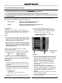
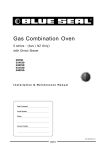
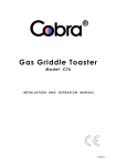
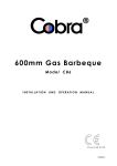
30DSERIES G32D5 (Digital Operation) Installation and Operation Manual This appliance is equipped for operation with:- Attach Gas Type Label Here For conversion to the other gas type, refer to ‘Gas Conversion’ instructions inside. 234784-11 MANUFACTURED BY Moffat Limited Christchurch New Zealand INTERNATIONAL CONTACTS AUSTRALIA Moffat Pty Limited Web: E.Mail: Main Office: Service: Spares: Customer Service: www.moffat.com.au [email protected] (tel) +61 (03) 9518 3888 (fax) +61 (03) 9518 3833 (tel): 1800 622 216 (tel): 1800 337 963 (tel): 1800 335 315 (fax): 1800 350 281 CANADA Serve Canada Web: E.Mail: Sales: Service: www.servecanada.com [email protected] (tel): 800 551 8795 (Toll Free) (tel): 800 263 1455 (Toll Free) NEW ZEALAND Moffat Limited Web: E.Mail: Main Office: www.moffat.co.nz [email protected] (tel): 0800 663328 UNITED KINGDOM Blue Seal Web: E.Mail: Sales: Spares: Service: www.blue-seal.co.uk [email protected] (tel): +44 121 327 5575 (fax): +44 121 327 9711 (tel): +44 121 322 6640 (fax): +44 121 327 9201 (tel): +44 121 322 6644 (fax): +44 121 327 6257 UNITED STATES Moffat Web: Sales: Service: www.moffat.com (tel): 800 551 8795 (Toll Free) (tel): +1 336 661 1556 (fax): +1 336 661 9546 (tel): 800 858 4477 (Toll Free) (tel): +1 336 661 1556 (fax): +1 336 661 1660 REST OF WORLD Moffat Limited Web: E.Mail: www.moffat.co.nz [email protected] The reproduction or copying of any part of this manual by any means whatsoever is strictly forbidden unless authorized previously in writing by the manufacturer. In line with policy to continually develop and improve its products, Moffat Ltd. reserves the right to change the specifications and design without prior notice. © Copyright Moffat Ltd. July 2012. Contents List G32 Turbofan Convection Oven. Model Numbers Covered in this Manual G32D5 - Turbofan Oven - 5 Tray Convection Oven. Introduction ........................................................................................................... 2 Safety Information Specifications ......................................................................................................... 3 Oven Gas Supply Requirements and Specifications Installation ............................................................................................................. 4 Installation Requirements Installation Unpacking Location Clearances Stand Mounted Ovens Electrical Connection Gas Connection Water Connection - (Optional) Positioning and Levelling of Oven Initial Start-Up Commissioning Operation ................................................................................................................ 7 Operation Guide Oven Control Panel Using the Oven - Manual Mode Cooking in Program Mode Setting the Oven Programs Oven Racks Operator Accessible Parameters .......................................................................... 12 Setting the Operator Accessible Parameters Table of ‘Operator Accessible Parameters’ Cleaning and Maintenance ................................................................................... 13 Cleaning Guidelines Oven Cleaning Periodic Maintenance Fault Finding ......................................................................................................... 16 Electrical Schematics ............................................................................................ 17 Gas Conversion and Specifications....................................................................... 18 Conversion Procedure Table of Gas Specifications Replacement Parts List......................................................................................... 19 Appendix 1 - Oven Door Reversal ........................................................................ 20 Introduction Before using your new oven, please read this instruction manual carefully, pay particular attention to any information labelled ‘WARNING’, ‘CAUTION’, ‘IMPORTANT’ or ‘NOTE’ in this manual. Warning Indicates a hazardous situation which, if not avoided, will result in death or serious injury. Caution Indicates a hazardous situation which, if not avoided, will result in minor or moderate injury. This manual must be kept by the owner for future reference. A record of the Date of Purchase, Date of Installation and Serial Number of the oven should be recorded in the area provided below. The serial number of this oven can be found on the Technical Data Plate located on the front right hand side panel, see diagram in ‘Installation Section’. Model Number: If you are unsure of any aspect of the installation, instructions or performance of your oven, contact your TURBOFAN dealer promptly. In many cases a phone call could answer your question. Serial Number: Dealer: Should you contact your TURBOFAN dealer on any matter concerning this oven, please have the information provided opposite, readily available. Service Provider: For your safety, please pay attention to the following symbols marked on the appliance. Date Purchased: - Risk of electric shock. No user serviceable parts inside. Date Installed: Qualified service person access only. Disconnect from power before servicing. Safety Information Instructions to be followed in the event the user smells gas are to be posted in a prominent location. This information shall be obtained by consulting the local gas supplier. FOR YOUR SAFETY MESURE DE SECURITÉ Do not store or use gasoline or other flammable vapours or liquids in the vicinity of this or any other appliance. Ne pas entreposer ni utiliser d’essence ni autres vapeurs ou liquides inflammables à proximité de cet appareil ou de tout autre appareil. WARNING: AVERTISSEMENT: Improper installation, adjustment, alteration, service or maintenance can cause property damage, injury or death. Read the installation, operating and maintenance instructions thoroughly before installing or servicing this equipment. L’installation, le réglage, la modification, la réparation ou l’entretien incorrect de cet appareil peut causer des dommages matériels, des blessures ou la mort. Lire attentivement les instructions d’installation, de fonctionnement et d’entretien avant de procéder à son installation ou entretien. Caution: Attention This appliance is; For professional use and is to be used by qualified persons only. Only qualified service persons are to carry out installation, servicing and gas conversion operations. Components having adjustments protected (e.g. paint sealed) by the manufacturer should not be adjusted by the user / operator. Cet équipement est : - Destiné à une utilisation dans un cadre professionnel et doit être utilisé uniquement par du personnel qualifié. - L'installation, la maintenance et la conversion du type de gaz doivent obligatoirement être effectuées par des techniciens agréés. - Les pièces dont les ajustements sont protégés (peinture) ne doivent pas être ajustées par l'opérateur / utilisateur. 2 Specifications G32D5 Restraint Device Anchor Point Oven Gas Supply Requirements and Specifications Input Rating Supply Pressure Operating Pressure Natural Gas LP Gas (Propane) 33,000 BTU/hr. 33,000 BTU/hr. (35 MJ/hr). (35 MJ/hr). 7” w.c. (1.75 kPa). 11” w.c. (2.75 kPa). 4.2” w.c. 11” w.c. (1.05 kPa). (2.75 kPa). Gas Connection ½” NPT. Electrical Power Ratings 1 Phase, 110-120V, 60HZ, 220W. Oven Tray Details Water Connection Tray Capacity 5 x US Full Pan. Tray Spacing 85 mm / 31/3”. ¾” BSP with ¾” GHT Adaptor supplied (80 psi / 550 kPa maximum pressure). 3 Installation Installation Requirements Important: Installation shall comply with local gas, electrical and health and safety requirements. It is most important that this oven is installed correctly and that oven operation is correct before use. If you have any questions regarding the proper installation and / or operation of this oven, please contact your local Turbofan distributor. This installation of this appliance must conform with local codes, or in the absence of local codes, must conform to the National Codes shown below covering gas and electrical safety. UNITED STATES: ANSI 223.1 / NFPA 54 National Fuel Gas Code. ANSI / NFPA70 National Electrical Code. CANADA: CSA B149.1 National Gas and Propane Installation Code. CSA C22.2 Canadian Electrical Code. Installation 5. Securely fit the 4 legs supplied with the oven. 6. Check that the available gas and electrical supply is correct to that shown on the Technical Data Plate located on the front right hand side panel. Installations must be carried out by authorised persons only. Failure to install equipment to the relevant codes and manufacturers specifications shown above, will void the warranty. Refer to ‘Specifications’ section, ‘Oven Specifications Tables’. NOTE: The oven and its individual shutoff valve must be disconnected from the gas supply piping system during any pressure testing of that system at test pressures in excess of 0.5psi (3.5 kPa). The oven must be isolated from the gas supply piping system by closing its individual manual shutoff valve during any pressure testing of the gas supply piping system at test pressures equal to or less than 0.5psi (3.5 kPa). This oven must be electrically earthed / grounded in accordance with local codes. Installation must allow for a sufficient flow of fresh air for the combustion air supply. Combustion air requirements: Natural Gas 350ft3/hr (10m³/hr). LPG 320ft3/hr (9m³/hr). Technical Data Plate Location Location Components having adjustments protected (e.g. paint sealed) by manufacturer are only to be adjusted by an authorised service agent. They are not to be adjusted by the installation person. 1. This oven must be installed in an area of adequate air supply. Adequate ventilation is essential, to prevent dangerous build up of combustion products. DO NOT obstruct the air flow around the ventilation slots. 2. This oven must be fitted on supplied legs in all installations. (When installed on a manufacturers stand, the legs are used to locate the oven in the correct position. 3. All air for burner combustion is supplied from underneath the appliance. The legs must always be fitted and no obstructions placed on the underside or around the base of the appliance, as obstructions will cause incorrect operation and / or failure of the appliance. 4. Installation must allow for a sufficient flow of fresh air for the combustion air supply. 5. The area around the appliance must be kept free and clear from combustibles. Unpacking 1. Remove all packaging and transit protection including all protective plastic coating from the exterior stainless steel panels. 2. Check the oven and supplied parts for damage. Report any damage immediately to the carrier and distributor. 3. Check that the following parts have been supplied with your oven:4 x Leg Adjustable. Adaptor Brass. USA / Canada only. Rubber Washer. 4. Report any deficiencies to the distributor who supplied your oven. 4 Installation Gas Connection 6. Position oven in its approximate working position. It should be positioned so that the control panel and oven shelves are easily reachable for loading and unloading. 7. Use a spirit level to ensure oven is level from side to side and front to back. (If this is not carried out, uneven cooking could occur). Clearances Important: For appliances installed on castors (double stacked, on base stand or on proofer), the installation shall be made with a connector that complies with:- ANSI Z21.69 • CSA 6.16 - Connectors for Moveable Gas Appliances. Important: and a Quick Disconnect Device that complies with:- The vent located on the top of the oven must NOT be obstructed. - ANSI Z21.41 • CSA 6.9, (2) - Quick Disconnect Devices for use with Gas Fuel. Adequate means must be provided to limit the movement of the appliance without depending on the gas connector and the quick-disconnect device or its associated piping to limit the appliance movement. The restraint anchor point is located below the gas connection point as shown. Oven Vent 1. To ensure correct ventilation for the motor and controller, the following minimum installation clearances are to be adhered to: Top Combustible Surface Non Combustible Surface 600mm / 24” 200mm / 8” LH / RH Side 75mm / 3” 75mm / 3” Rear 75mm / 3” 75mm / 3” Restraining Anchor Point A ½" N.P.T connection is provided at the bottom rear of the oven. It is important that adequately sized piping run directly to the connection joint on the oven with as few tees and elbows as possible to give maximum supply volume. A suitable jointing compound which resists the break down action of LPG must be used on every gas connection. Check all gas connections for leakages using soapy water or other gas detecting equipment. CLEARANCE FROM SOURCE OF HEAT. A minimum distance of 300mm (12”) from the appliance sides is required. Warning Do not use a naked flame to check for gas leakages. NOTE: Fixed installations require at least 500mm (20”) clearance at the right hand side of oven for service access. Check the technical data plate located on the front right hand corner of the oven, for correct operating pressure and gas orifice size for the gas being used, before operation. Stand Mounted Ovens For ovens that are to be mounted to a stand, the oven legs are used to level the oven on the stand. Refer to the instructions supplied with separately ordered stands for mounting details. The appliance combination gas valve is fitted with an internal regulator for adjusting operating pressure. To access, remove appropriately marked service panel from beneath oven door. Unscrew and remove regulator cap from gas valve. Electrical Connection Adjust regulator to achieve stated pressure. Also refer to ‘Specifications’ section. Warning Regulator Cap Electrical Grounding Instructions This appliance is equipped with a three-prong (grounding) plug for your protection against shock hazard and should be plugged directly into a properly grounded threepronged receptacle. Do not cut or remove the grounding prong from this plug. Each oven should be connected to an adequately protected power supply and an isolation switch mounted adjacent to, but not behind the oven and must be readily accessible to the operator. This switch must be clearly marked and readily accessible in case of fire. Pressure Test Point (shown connected for testing) NOTE: The Pressure Test Point is located behind the front service panel beneath the oven door. Check electricity supply is correct to as shown on Technical Data Plate on front right hand corner of oven side panel. Ensure oven is fitted with appropriate power cord and plug. 5 Installation Water Connection - Optional (Not required for Main Oven Operation) 1. If the manual addition of water into the oven for humidification or steaming effect on baked product is required, the unit’s water connection can be used. 2. Tighten the 2 screws securing the water connection to the rear of the oven. (These have purposely been left loose to prevent damage to the water connection during transit). Tighten Screws. 3. A cold water supply should be fitted to the water inlet (¾” BSP hose connection) which is located on the rear of the right hand side of the oven. 4. Connect to the water supply. - Max Inlet Pressure 80psi / 550kPa. 5. Turn ‘On’ the water supply and check for leaks. Positioning and Levelling of Oven 1. Correctly locate the oven into its final operating position and using a spirit level, adjust the oven feet so that the oven is level and at the correct height. Initial Start-Up Before using the new oven; 1. For first time use of the oven, operate the oven for about 1 hour at 200°C / 400°F to remove any fumes or odours which may be present. 2. Refer to the Operation Section of this manual for details on how to correctly operate and shutdown the oven. Commissioning Before leaving the new installation; Check the oven functions in accordance with the operating instructions specified in the ‘Operation’ section of this manual. Lighting the oven. Turning ‘Off’ the oven. Ensure that the operator has been instructed in the areas of correct lighting, operation, and shutdown procedure for the appliance. NOTE: If for some reason it is not possible to get the appliance to operate correctly, shut off the gas supply and contact the supplier of this appliance. 6 Operation Operation Guide Warning Warning Take care when opening the oven door during baking. Let hot air and steam escape before removing or replacing food as the steam produced can cause steam burns. Some parts of this oven will become VERY HOT during use and could cause burns if touched. Turbofan Ovens have been designed to provide simple operation. This oven is intended for use in a commercial kitchen and must only be put to the use for which it was intended, i.e. cooking food product. To use this oven correctly please read the following sections carefully:- Oven Control Panel Temperature Display - Shows the Programming Button and LED - preset chamber temperature. When used with ‘Temperature’ button, shows actual oven temperature for 5 seconds. Shows Cooking Modes and Error Codes. Used to enter the ‘Programming’ mode. Temperature Button and LED Shows actual oven temperature for 5 seconds on the Temperature Display. LED ‘On’ when heating; LED flashes when showing actual temperature. Steam Button and LED - Activates the ‘Steam Mode’. Temperature Adjustment Control. Time Display - Shows cook time in full Light On / Off Button and LED - minutes only from 180 - 1, and seconds for final minute only. Turns oven light ‘On / Off’. On / Off / Stand-By Button and LED - Press ‘On / Off’ button once to Start / Stop Button and LED Pressing the ‘Start / Stop’ button oven switches between ‘Time Start’ and ‘Temporary Pause’ Modes. LED will flash when timer is paused. When in the cooking cycle, pressing the ‘Start / Stop’ button for 2 seconds will end the cooking cycle. turn the oven ‘On’. Press and hold ‘On / Off’ button for 2 seconds to turn the oven ‘Off’. Time Adjustment Control. Lighting the Oven Oven Shut-Down 1. Ensure that the gas supply is turned ‘On’ at the gas supply. 2. Turn ‘On’ electrical power to the oven. The controller will carry out a self check of the LED’s. 3. Press the ‘On/Off’ Button. 4. The Heating Indicator will illuminate, after a slight delay the oven burner will ignite automatically. - Should the first ignition attempt fail, the oven will automatically attempt 2 more ignitions. - If these also fail, the oven will go to ‘Lock-Out’. - Refer to ‘Fault Finding’ section for further details. 1. To turn ‘Off’ the oven, press and hold the ‘On/Off’ button for 3 seconds, the burner will extinguish and the oven controller will go to ‘Stand-By’ mode. Wait minimum 5 min. before relighting the oven. 7 Operation Using the Oven - Manual Mode 1. To check actual oven temperature during preheat or cooking, press ‘Temperature’ button. Actual temperature will display briefly on ‘Temperature Display’ before the display reverts to the pre-set temperature. TURN ‘ON’. Press ‘On-Off’ button. Temperature Dislay. Temperature Display will show Preset temperature. 2. Heating ‘On’ Indicator SET TEMPERATURE. + to increase the temperature. - to decrease the temperature. At any time during cooking, time and temperature can be adjusted by using the ‘Time’ / ‘Temperature’ controls. Time Display. Time Display will show actual time set. Timer ‘On’ Indicator Power ‘On’ Indicator 3. This oven can be used without using the ‘Timer’. SET TIME. + to increase the time. - to decrease the time. 4. If the ‘Timer’ is set to the ‘Infinity’ setting , the timer will count elapsed time to a maximum of 999 minutes. START TIMER. Press ‘Start / Stop’ button to start timer operation. Pressing and Holding ‘Start / Stop’ button for 3 seconds will reset the timer. Pressing the ‘Start / Stop’ button when timer is operating will pause the timer and turn ‘Off’ Fan and Heating. LED will flash when timer is paused. Opening the oven door during a cooking cycle will pause the cooking time. To continue cooking, close the oven door. - Press any button, to cancel the ‘Alarm’. - Press ‘Steam’ button, to select the Steam mode. - Press ‘Act Temp’ button, to check ‘Actual’ temperature of oven at any time during cooking. - Press ‘Light’ button, to turn ‘On’ oven light. (refer - ‘Operator Accessible Parameters’). - Press ‘Program’ button, to program the Oven refer to the ‘Installation and Operation Manual’. - Press and hold ‘On / Off’ button, for 3 seconds to turn ‘Off’ the Oven. Steam; - Steam function can be selected at any time during the Manual Mode by pressing the ‘Steam’ button. Steam will be injected for the pre-set time and the ‘Steam’ LED will illuminate. Refer to ‘Operator Accessible Parameters’ for steam options. 8 Operation Cooking in Program Mode 1. TURN ‘ON’. Press ‘On-Off’ button. Press ‘Programs’ button. Program Mode Indicator Heating ‘On’ Indicator Temperature Dislay. Temperature Display will show program selected. 2. To check actual oven temperature during preheat or cooking, press ‘Temperature’ button. Pre-Set temperature will display briefly on ‘Temperature Display’ before the display reverts to the actual temperature. SELECT A PROGRAM. + to scroll forward through programs. - to scroll backward through programs. Time Display. Time Display will show ‘Pre-Heating’. Program cannot be started until pre-heating is completed. When cooking in ‘Program’ mode, the oven light will remain ‘On’ until cooking is completed. Load Oven. ‘Time’ display will show ‘Ready’. 3. Opening the oven door during a cooking cycle will pause the cooking time. To continue cooking, close the oven door. START PROGRAM. Press ‘Start / Stop’ button to start cooking program. Pressing the ‘Start / Stop’ button when timer is operating will pause the timer and turn ‘Off’ Fan and Heating. LED will flash when timer is paused. Temperature and Time can be adjusted when in Program Mode. On program completion, oven reverts to the pre-set temperature for that program. Pressing and Holding ‘Start / Stop’ button for 3 seconds will cancel the program and return to Preset Program. - Press any button, to cancel the ‘Alarm’. - Press ‘Steam’ button, to select the Steam mode. - Press ‘Act Temp’ button, to check ‘Actual’ temperature of oven at any time during cooking. - Press ‘Program’ button, to program the Oven refer to ‘Setting the Oven Programs’ overleaf. - Press and hold ‘On / Off’ button, for 3 seconds to turn ‘Off’ the Oven. Steam; - Steam function can be selected at any time during the Program Mode by pressing the ‘Steam’ button. Steam will be injected for the pre-set time and the ‘Steam’ LED will illuminate. Refer to ‘Operator Accessible Parameters’ for steam options. 9 Operation Setting the Oven Programs Oven can be pre-programmed with up to 20 Program’s. When you receive your oven, the controller is not programmed. To set programs, carry out the following for each program required:- 1. ENTER PROGRAMMING MODE. Press ‘Programs’ button to enter ‘Programming’ mode. 2. SELECT PROGRAM REQUIRED. Heating ‘On’ Indicator Rotate ‘Temperature Control’ to program required. Temperature Display will show program selected. Press and hold ‘Temperature’ button until ‘Time’ and ‘Temperature’ displays and ‘Temperature’ LED flashes. Change time and temperature parameters. 3. ENTER COOK TEMPERATURE. Rotate ‘Temperature Control’ to set cook temperature. + to increase the temperature. - to decrease the temperature. Timer ‘On’ Indicator ‘Temperature’ Display will show temperature selected. 4. ENTER COOK TIME. Rotate ‘Timer Control’ to set cook time. + to increase the time. - to decrease the time. ‘Time’ Display will show time selected. ‘Time’ and ‘Temperature’ displays and ‘Temperature’ LED flash. Press ‘Temperature’ button to confirm ‘Time’ and ‘Temperature’ settings. 5. SET STEAM OPTION. Hold ‘Steam’ button pressed until ‘Steam’ LED flashes and present setting displays in ‘Temperature’ display. Rotate ‘Temperature Control’ to set steam time required. + to increase steam time. - to decrease steam time. Press ‘Steam’ button to confirm ‘Steam’ settings. 10 Operation Oven Racks The oven is supplied with four general purpose oven racks. Self Supporting: When fitted, the oven racks are self supporting and will not drop or angle down when the racks are withdrawn during operation, when loading and unloading products onto racks or when attending to the product being cooked during it’s cook cycle. NOTE: Ensure that the racks are correctly fitted to the oven with the raised part of the rack to the rear of the oven and the hooks on the underside of the rack engaged below the rack runner. Fit racks with raised part of rack to the rear of the oven Ensure that these hooks are located under the rack runners when fitting the shelves to the oven. 11 Operator Accessible Parameters Setting the Operator Accessible Parameters 1. ENTER THE OPERATOR PARAMETER MODE. Press 'Steam' and 'Start / Stop' buttons together. ‘Temperature’ Display will show ‘PAS’. The ‘Time’ Display will flash. 2. SET PASSWORD. Rotate ‘Timer Control’ to set password; (123) (Operator Password). Press ‘Light On / Off’ button to confirm password. ‘Temperature’ Display will show one of Parameter Codes. ‘Time’ Display will show value of the parameter. 3. SETTING THE PARAMETERS. Rotate ‘Timer Control’ to parameter required. Press ‘Light’ button to confirm parameter. ‘Time’ display will flash. While ‘Time’ display is flashing, rotate ‘Timer Control’ to select value required. Press ‘Light’ button to confirm value. ‘Time’ display will stop flashing. 4. EXITING THE PARAMETER MODE. Press ‘On-Off’ button, to return to ‘Stand-By’ mode. Table of Operator Accessible Parameters Parameter Number Description Turn -On Pre-Heating temperature - (60 - 260˚C / 140 - 500˚F). Default Setting 150ºC (325ºF) Light Auto ‘Off’ Setting Time 0 = ‘On/Off’. 1 = 1 minute auto ‘Off’. 2 = 2 minutes auto ‘Off’, etc. 1 Steam Injection setting time 0 = Steam will be emitted for as long as ‘Steam’ button is pressed. 1 = Steam will be emitted for 1 second. 2 = Steam will be emitted for 2 seconds, etc. 0 Buzzer Volume - Can be adjusted from ‘0’ to ‘10’. 5 Program Pre-Heating Condition - (Can be adjusted from 0 to 30ºC {0 to 54ºF} above pre-heat temperature). 12 20ºC (36ºF) Cleaning and Maintenance Cleaning Guidelines Rack Securing Screw Caution Always turn off electrical power at the mains supply before commencing cleaning. Unscrew Anti-Clockwise This oven is not water proof. Do not use water jet spray to clean interior or exterior of the appliance. b. Lift up and unhook rear of rack from locating peg at rear of oven. NOTE: If this appliance is fitted with a Restraint Device, the device must be dis-connected prior to moving the appliance for cleaning. Always ensure that the restraining device is re-connected on completion of the cleaning operation. To achieve the best results, cleaning must be regular and thorough. If any small faults occur, have them looked at promptly. Don't wait until they cause a complete breakdown. R/Hand Rear Locating Peg NOTE: Carefully read and follow the safety instructions on c. Tilt top of rack inwards and lift rack off lower mounting brackets. the label of the cleaning product to be used. DO NOT use harsh abrasive scouring pads or abrasive detergents as they could damage the oven. Left Rack Ensure that any detergent or cleaning material has a. Lift LH rack off front locating peg. been completely removed after each cleaning. To keep your oven clean and operating at peak efficiency, follow the procedures shown below:Oven Cleaning NOTE: If oven usage is very high, the cleaning procedure should be carried out on a more frequent basis. L/Hand Front Locating Peg Allow the oven interior to cool to approx 50˚C / 120˚F before commencing cleaning. b. Pull rack forward out of oven to disengage rear of rack from rear location peg and remove rack from oven. Stainless Steel Surfaces a. Thoroughly clean exterior surfaces of oven with, a damp cloth moistened with a mild detergent solution, or a soft bristled brush. L/Hand Rear Locating Peg b. Baked on deposits or discolouration may require a good quality stainless steel cleaner. Always apply cleaner when oven is cold and rub in direction of grain. Side Racks Removal Right Rack / Fan Baffle a. Undo and remove rack securing screw securing front of RH side rack. The fan baffle is an integral part of RH Side Rack. c. Clean the racks with a mild anti bacterial detergent and hot water, using a soft bristled brush. d. Dry the racks thoroughly with a dry cloth. 13 Cleaning and Maintenance Side Racks Re-Fitting Right Rack Lamp Glass a. Remove the LH side rack as shown previously. a. Align the bottom of the rack with the 2 brackets in the bottom RH side of the oven. b. Unscrew (anti-clockwise) and remove the lamp glass from the oven. L/Hand Front Locating Peg RH Lower Mounting Brackets b. Tilt the rack upwards and hook the top rear of the rack onto the locating peg in the top rear of the oven. Unscrew Anti-Clockwise R/Hand Rear Locating Peg c. Remove seal fitted between lamp glass and holder. c. Fit and tighten the rack securing screw to secure the front of the RH rack. Tighten Clockwise Remove Seal d. Wash the lamp glass and seal with a soft sponge using warm water and a detergent solution. Rinse with clean, warm water and dry off. Left Rack a. Locate the top rear of the rack onto the locating peg at the top rear LH side of the oven. e. Dry the lamp glass thoroughly with a dry cloth. L/Hand Rear Locating Peg NOTE: The lamp glass seal must be fitted with the flat face of the seal towards the lamp glass. f. Refit the lamp glass, screw the glass in clockwise to secure. Do not over tighten lamp glass. g. Refit the LH side rack as shown previously. b. Locate the top front of the rack over the locating peg at the top front LH side of the oven. 14 Cleaning and Maintenance Door Seal a. To remove the door seal, pull the 1 piece seal forward until it pulls out of the location groove around the oven. Note the way the seal is fitted to the oven, with the lip facing inwards. Door Glass Cleaning Ensure that the oven door is cool before cleaning the oven door glass. a. Open the oven door. b. Lift up the bottom of the inner glass at the centre of the door to unlock from the inner glass retaining catches and swing the glass inwards towards the oven. b. Check the door seal for wear and damage and replace as required. c. Wash the door seal in a sink, taking care not to cut or damage the seal. d. Dry the door seal thoroughly. e. Refit the door seal with lip facing into centre of the oven. Top Locking Catches Push Seal carefully into locating channel c. Clean both sides of the inner glass and the inner side of the outer door glass with a conventional glass cleaner. d. Dry the oven door thoroughly with a soft dry cloth. e. Swing the inner glass back towards the outer door. f. Press the door seal into the locating groove in the front face of the oven until the seal is properly located all around the oven. f. Whilst holding the outer door, lift the inner glass back onto the locking catches until the inner glass is securely held. Oven Interior Periodic Maintenance Allow the oven interior to cool to approx 50˚C / 120˚F before commencing cleaning. Important: a. Remove the oven racks as shown previously. When appliances are installed on castors (double stacked, fitted on base stands, or on a proofer) and connected to the gas supply piping by means of a connector for moveable appliances, the appliance is fitted with a restraining device. If disconnection of the restraining device is necessary, ensure that it is re-connected once the appliance is returned to its original operating position. b. Clean any build up of grease from the oven interior, using a soft bristled brush with a solution of hot water and a mild anti bacterial detergent. c. Dry the oven thoroughly with a soft dry cloth. d. Clean the oven regularly with a good quality oven cleaner. NOTE: All maintenance operations should only be carried out by a qualified service person. Controls and mechanical parts should be checked and adjusted periodically by a qualified service person. It is recommended that the appliance is serviced every 6 months. 15 Fault Finding You may encounter a problem not covered in this section, please contact your service provider who will require the following information:- This section provides a reference to the more common problems that may occur during the operation of your oven. This fault finding guide is intended to help you correct and accurately diagnose problems with your oven. The Model and Serial Number of the oven, can be When fault finding a problem, always use a process of elimination starting with the simplest solution and working through to the most complex. Never overlook the obvious. Fault Oven does not operate. found on the Technical Data Plate located on the front right hand side panel of the oven. Possible Causes Remedy Mains isolating switch, circuit breaker or fuses are 'Off' at the power board. Turn 'On'. Overtemp tripped (No lights, no power light). Call for service. Overtemp faulty. Call for service. Digital Controller faulty Call for service. No gas supply to oven. Check gas supply. Turn oven OFF then ON to reset ignition control. Gas Valve faulty. Call for service. Ignition control is in lock-out. Turn oven OFF then ON to reset ignition control. Door not fully closed. Close door (refer ‘Door does not close fully’). Door microswitch faulty. Call for service. Ignition control faulty. Call for service. Fan motor faulty. Call for service. Fan or fan motor obstructed. Call for service. Injector Nozzle blocked. Call for service. Water Solenoid faulty. Call for service. Controller faulty. Call for service. Tray in way of door. Correctly position tray in rack. Door mis-aligned. Re-align door. Door seal obstruction. Correctly install door seal. (Refer to the ‘Cleaning’ Section). Blown bulb. Replace bulb. Too high a temperature selected. Select a lower temperature. Oven or racks not level. Check oven racks and level. Insufficient air space around trays or baking tins. Ensure oven racks are spaced to allow air flow around baking on all shelves. Oven overloaded with too much product. Re-load oven. Opening oven door un-necessarily. Ensure oven door remains closed during the baking process. Oven door seal damaged or faulty. Check seals and replace if damaged. Oven vent restricted. Ensure oven vent not blocked or shrouded. Probe error. Call for service. Burner Box thermal overload switch tripped. Call for service. Oven Controller operates but:a. b. Sparking operates (3 attempts) but flame not established. No Sparking. Oven heats up but fan does not operate. Oven does not Steam. Door does not close fully. Oven light not illuminating. Uneven cooking. ‘Err 001’ on display. ‘Err 003’ on display. 16 Electrical Schematics Electrical Schematic G32D5 Turbofan Oven 17 Gas Conversion and Specifications Conversion Procedure 4. Unscrew and remove the main burner injector and replace with appropriate item. Caution Main Burner Injector Ensure that the appliance is isolated from the electrical and gas supply before commencing servicing. NOTE: These conversions should only be carried out by qualified persons. All connections must be checked for leaks before re-commissioning the appliance. Adjustment of components that have adjustments / 5. Connect gas and electrical supplies. 6. Operate oven and adjust the plastic adjust screw on the regulator to achieve correct pressure at pressure test point (front RH corner). 7. Refit the regulator cover screw to the gas valve. 8. Conduct full leak test of the converted oven prior to placing it into operation. settings sealed (e.g. paint sealed) can only be adjusted in accordance with the following instructions and shall be re-sealed before re-commissioning this appliance. For all relevant gas specifications refer to the table at the end of this section. Procedure: Warning 1. Remove the lower service panel to allow access to the gas control valve. 2. Unscrew and remove the regulator cover screw from the regulator incorporated in the gas control. Do not use a naked flame to check for gas leakages. 9. Refit the service panels. Gas Type Identification Label Cover Screw On completion of the gas conversion, replace the gas type identification label with the appropriate label, located at:- The rear of the appliance, above the gas connection. Commissioning Before leaving the converted installation; 1. Check all gas connections for leakages using soapy water or other gas detecting equipment. 2. Check the following functions in accordance with the operating instructions specified in the ‘Operation’ section of this manual. 3. Remove the plastic adjusting screw and regulator spring from the gas control valve. Replace with correct spring supplied with the conversion kit. Ensure that all the oven controls operate correctly. Ensure that the operating pressure remains correct. 3. Ensure any adjustments done to components that have the adjustments / settings sealed (e.g. paint sealed), are re-sealed. NOTE: If for some reason it is not possible to get the appliance to operate correctly, shut off the gas supply and contact the supplier of this appliance. Gas Specifications Table Natural Gas LP Gas (Propane) #36 Drill (2.70mm). #51 Drill (1.70mm). Green Spring. Blue Spring. Supply Pressure 7” w.c. (1.75 kPa). 11” w.c. (2.75 kPa). Operating Pressure 4.2” w.c. (1.05 kPa). 11” w.c. (2.75 kPa). Orifice Size Regulator Spring (Colour) 18 Replacement Parts List Important: Only genuine authorized replacement parts should be used for the servicing and repair of this oven. The instructions supplied with the parts should be followed when replacing components. For further information and servicing instructions, contact your nearest authorized service provider or Turbofan Dealer. When ordering replacement parts, please quote the part number and the description as listed below. If the part required is not listed below, request the part by description and quote model number and serial number which is shown on the Technical Data Plate. Item Description 234632 Digital Control Board Kit 234434 Temperature Probe 20 mm PT1000 1 mtr 234450 Encoder 022909 Ignition Electrode Assembly 025400 Overtemp 360°C / 680°F 232552 Capacitor 12uF (110V Models) 232905 Fan Motor 110-120V 60HZ 234461 Cooling Fan 110-120V 50/60HZ 232903 Fan Dia 175mm / 7” 234430 Transformer 110-120V x 12VAC SEC 15VA 234459 Ignition Module Fenwal 120V 234458 Gas Valve G32 120V 232964 Thermal Switch 150°C 004952 Burner Painted 032170 Injector 1.70 mm 032270 Injector 2.70 mm NAT 235435 Gas Type Conversion Kit USA / Canada Only 015311 Test Point Plug 1/8” NPT 234447 Knob Indexed 234751 Door Switch Actuator 024802 Door Microswitch 232666 Door Seal 234580 Door Roller Catch 235277 Door Roller Catch Strike 235278 Strike Lock Nut 234626 Door Hinge Top 234627 Door Hinge Bottom 234757 Door Inner Glass Assembly 234752 Hinge Pivot Kit 233884 Lamp Bulb G9 25W, Halogen 120V 233115 Oven Lamp Lens 233883 Oven Lamp Seal 021617 Water Solenoid 90° Outlet 120V 025922 Adaptor Brass (USA / Canada only) 021527 Washer Rubber (USA / Canada only) 233986 Foot Adjustable 100 mm 233649 Oven Rack 234658 Oven Side Rack LH 5-tray 234667 Oven Side Rack RH 5-tray 233552 Rack Securing Screw LPG (Propane) 19 Appendix 1 - Oven Door Reversal 11. Remove inner glass latching studs and fit to opposite side of door using Loctite 243 to secure. Reversing the Oven Door Refit all screw fasteners using a low-mid strength thread locking adhesive unless otherwise stated. Door reversal should only be carried out by a Remove Latching Studs suitably competent person. Remove the Oven Door Inner Glass. 1. Open the oven door and open Remove Screw the door inner glass. and Retaining 2. Remove screw securing inner Clip. glass retaining clip and remove clip. 3. Lift up inner glass and remove, ensuring that pivot spacer is removed from lower inner glass pivot and retained. 12. Turn door handle over and fit to other end of door where hinges were removed from. Ensure Flat of handle is to the outside. Remove Upper and Lower Door Hinges and Door Catch. 13. Remove bottom door pivot bolt and spacers and fit pivot bolt to top door hinge assembly (as this will be swapped over and fitted to bottom of other side of oven). Fit Blanking Plugs. 4. Remove black plastic plugs from top and bottom of door and fit to holes where inner glass pivots were removed from. 14. Remove the 4 blanking screws from front of oven. Remove the Oven Door. 5. Remove the door roller catch and blanking plate from the inside of the door and swap these over. Swap Roller Catch and Blanking Plate over. 6. Whilst supporting door, unscrew and remove top door pivot bolt from top door hinge assembly. 7. Remove door and lay on a flat surface or workbench. 8. Unscrew screws securing the door handle remove door handle. 9. Remove top door hinge and fit to bottom opposite corner of door. Remove screws top and bottom and fit to where hinges removed from. Remove Top Door Pivot Bolt. 15. Remove Hinge Plate from top of oven and fit diagonally opposite, to lower corner. Remove these screws to remove top and bottom hinges. Remove Handle Securing Screws 10. Remove bottom door hinge and fit to top opposite corner of door. Bottom Door Pivot Bolt and Spacers. 16. Remove Hinge Plate from bottom of oven and fit diagonally opposite, to upper corner. 17. Fit screws removed at Item 14 above to where hinges were fitted. Remove Top Door Hinge 20 Appendix 1 - Oven Door Reversal 18. Remove Blanking Screw and Door Catch from front of oven and swap around (refer ‘Adjusting Door Catch’). Door Catch Adjust Door for Correct Alignment. Check alignment and operation of the door. Ensure that the door is correctly aligned horizontally and vertically. 1. To align, slacken off the upper and lower hinge plates and correctly align the door. Re-tighten both hinge plates. 2. Check that the roller catch correctly retains door in the Slacken these screws to adjust closed position. door vertically - horizontally. 3. To adjust, slightly loosen screws securing roller catch and close the door. The roller catch will centralise itself. 4. Open door and tighten roller catch securing screws. Blanking Screw Locking Nut 19. Fit door spacers removed at Item 13 previously, to lower hinge pivot bolt. Oven Door Re-Fitting Fit the Door. 1. Refit oven door by locating bottom of door onto bottom hinge plate pivot bolt and spacers. 2. Fit top of door into top hinge plate and secure with top pivot bolt. Top Door Pivot Bolt. Adjusting Door Catch If the door sealing requires adjustment, carry out the following to adjust the door catch:1. Check that the door seals correctly when closed, by placing a sheet of paper between the door and the seal. 2. Close the door on the paper and attempt to withdraw the paper by firmly tugging on the paper. The paper should just pull out with some resistance but without tearing. Fit Inner Glass to Door. NOTE: It is important to ensure that the inner glass is fitted correctly and that the glass pivots at the hinge end of the door and not the handle end. 3. Fit pivot spacer removed at Item 3 on previous page, to the lower inner glass pivot and locate inner glass lower pivot into position on inside of door. 4. Locate top pivot of inner glass Screw and into top of door and secure in Retaining Clip. position with inner glass retaining clip. 5. Lift inner glass up onto locking catch to lock glass into position. 3. To adjust the door catch, loosen the locking nut on the door catch:a. If the paper withdraws easily, screw the door catch ‘In’ by ½ a turn and repeat the test above until adjusted correctly. b. If the paper cannot be withdrawn and the door springs open, screw the door catch ‘Out’ by ½ a turn and repeat the test above until adjusted correctly. 4. Tighten the locking nut on the door catch. Inner Glass Locking Catch 21